EP0971087A1 - Padlock - Google Patents
Padlock Download PDFInfo
- Publication number
- EP0971087A1 EP0971087A1 EP98305394A EP98305394A EP0971087A1 EP 0971087 A1 EP0971087 A1 EP 0971087A1 EP 98305394 A EP98305394 A EP 98305394A EP 98305394 A EP98305394 A EP 98305394A EP 0971087 A1 EP0971087 A1 EP 0971087A1
- Authority
- EP
- European Patent Office
- Prior art keywords
- lock
- leg portion
- plunger
- shackle insert
- shackle
- Prior art date
- Legal status (The legal status is an assumption and is not a legal conclusion. Google has not performed a legal analysis and makes no representation as to the accuracy of the status listed.)
- Withdrawn
Links
Images


Classifications
-
- E—FIXED CONSTRUCTIONS
- E05—LOCKS; KEYS; WINDOW OR DOOR FITTINGS; SAFES
- E05B—LOCKS; ACCESSORIES THEREFOR; HANDCUFFS
- E05B67/00—Padlocks; Details thereof
- E05B67/06—Shackles; Arrangement of the shackle
- E05B67/22—Padlocks with sliding shackles, with or without rotary or pivotal movement
- E05B67/24—Padlocks with sliding shackles, with or without rotary or pivotal movement with built- in cylinder locks
-
- E—FIXED CONSTRUCTIONS
- E05—LOCKS; KEYS; WINDOW OR DOOR FITTINGS; SAFES
- E05B—LOCKS; ACCESSORIES THEREFOR; HANDCUFFS
- E05B9/00—Lock casings or latch-mechanism casings ; Fastening locks or fasteners or parts thereof to the wing
- E05B9/08—Fastening locks or fasteners or parts thereof, e.g. the casings of latch-bolt locks or cylinder locks to the wing
- E05B9/084—Fastening of lock cylinders, plugs or cores
Definitions
- This invention relates to a padlock, more particularly to a padlock having a lock device that is suitable for use with lock bases of different sizes.
- Figure 1 illustrates a conventional padlock which includes a lock base 10, a lock device 11, two ball members 12, and a U-shaped shackle 13.
- the lock base 10 is formed with two shackle insert holes 16 for receiving longer and shorter leg portions of the shackle 13, a lock receiving space 14 between the shackle insert holes 16 for receiving the lock device 11, and two ball chambers 15 on opposite sides of an upper section of the lock receiving space 14 to communicate the lock receiving space 14 with the shackle insert holes 16, respectively.
- the lock device 11 is formed with an engaging rim 111 for retaining the lock base 10 in the lock receiving space 14.
- the lock device 11 has an upper end formed with a plunger 112 which has two opposite latch portions 113 for actuating the ball members 12, respectively.
- the ball members 12 When the padlock is in a locking state, the ball members 12 are pushed by the latch portions 113 of the plunger 112 to extend into the shackle insert holes 16 for engaging ball retaining grooves 131 formed in the longer and shorter leg portions of the shackle 13 in order to prevent upward movement of the shackle 13 and removal of the shorter leg portion from the corresponding shackle insert hole 16.
- the plunger 112 When the lock device 11 is operated using the correct key (not shown) to rotate a lock core (not shown) in the lock device 11, the plunger 112 is rotated to permit retraction of the ball members 12 into the ball chamber 15 for disengaging the shackle 13, thereby permitting upward movement of the shackle 13 and removal of the shorter leg portion from the corresponding shackle insert hole 16 for placing the padlock in an unlocked state.
- the main object of the present invention is to provide a padlock having a lock device that is suitable for use with lock bases of different sizes.
- the padlock of the present invention includes a lock base, a lock device, a locking unit, a shackle, and a biasing spring.
- the lock base has top and bottom sides, and is formed with first and second shackle insert holes which extend from the top side toward the bottom side.
- the first shackle insert hole has a length longer than that of the second shackle insert hole.
- the lock base is further formed with a lock receiving space which extends from the bottom side toward the top side and which is disposed between the first and second shackle insert holes.
- the lock receiving space has an upper section communicated with the second shackle insert hole.
- the lock base is further formed with a ball chamber which extends transversely between the first shackle insert hole and the upper section of the lock receiving space.
- the lock device is received in the lock receiving space, and has an axially rotatable key-operated lock core which is provided with a plunger that is disposed in the upper section of the lock receiving space.
- the plunger is formed with a latch projection.
- the locking unit includes at least one ball member rollingly disposed in the ball chamber adjacent to the plunger.
- the shackle has a longer leg portion which is retained slidably and rotatably in the first shackle insert hole, and a shorter leg portion which is received removably in the second shackle insert hole.
- the shorter leg portion is formed with a plunger engaging groove for engaging the latch projection of the plunger.
- the longer leg portion is formed with a ball retaining groove for engaging the locking unit.
- the biasing spring is disposed in the first shackle insert hole and biases the longer leg portion upwardly.
- the lock core is rotatable so as to rotate the plunger between a locking position, in which the latch projection of the plunger engages the plunger engaging groove in the shorter leg portion and in which the locking unit engages the ball retaining groove in the longer leg portion to arrest upward movement of the longer and shorter leg portions against action of the biasing spring in order to prevent removal of the shorter leg portion from the second shackle insert hole, and an unlocking position, in which the latch projection is disengaged from the plunger engaging groove in the shorter leg portion, and the longer leg portion is moved relative to the locking unit due to the action of the biasing spring for disengaging the locking unit, thereby permitting removal of the shorter leg portion from the second shackle insert hole.
- the padlock of the first preferred embodiment according to the present invention is shown to include a lock base 20, a generally U-shaped shackle 30, a lock device 50, a locking unit 28, and a biasing spring 31.
- the lock base 20 is formed from a body part 200 and a cover member 40 which is secured to the body part 200 at a front opening 27 of the latter, such as by welding.
- the lock base 20 is formed as a generally rectangular body with top and bottom sides, and is formed with spaced first and second shackle insert holes 22, 21 which extend from the top side toward the bottom side.
- the first shackle insert hole 22 has a length longer than that of the second shackle insert hole 21.
- the lock base 20 is further formed with a lock receiving space 23 which extends from the bottom side toward the top side and which is disposed between the first and second shackle insert holes 22, 21.
- the lock receiving space 23 has a rectangular lower section, and an upper section which is communicated with the second shackle insert hole 21.
- the lock base 20 is further formed with a ball chamber 24 which extends transversely between the first shackle insert hole 22 and the upper section of the lock receiving space 23, and a fastener hole 26 which extends between the first shackle insert hole 22 and the lock receiving space 23 below the ball chamber 24.
- the ball chamber 24 has a circular cross-section and a predetermined length for receiving the locking unit 28 that consists of a predetermined number of ball members 280 therein.
- the fastener hole 26 has a nut-retaining hole portion 260 with a hexagonal cross-section.
- the lock base 20 has a surrounding wall between the top and bottom sides and formed with an access bore 25 which extends into the first shackle insert hole 22 and which is aligned with the fastener hole 26.
- the lock device 50 is received in the lock receiving space 23, and has a lower end formed as a rectangular head portion which is retained in the rectangular lower section of the lock receiving space 23.
- the lock device 50 is provided with an axially rotatable lock core 51 which has a plunger 53 that is disposed in the upper section of the lock receiving space 23.
- the plunger 53 is formed with a generally rectangular latch projection 52.
- the length of the ball chamber 24 is suitable for receiving a locking unit 28 which includes two ball members 280.
- the ball members 280 are rollingly disposed in the ball chamber 24 adjacent to the plunger 51.
- the shackle 30 includes a longer leg portion 32 which is slidably and rotatably retained in the first shackle insert hole 22, and a shorter leg portion 34 which is received removably in the second shackle insert hole 21.
- the longer leg portion 32 has an inner side facing the shorter leg portion 34 and formed with a curved ball retaining groove 33 for engaging one of the ball members 280 of the locking unit 28 that is disposed immediately adjacent to the longer leg portion 32.
- the shorter leg portion 34 has an inner side facing the longer leg portion 32 and formed with a generally rectangular plunger engaging groove 35 for engaging the latch projection 52 of the plunger 53.
- the biasing spring 31 is disposed in the first shackle insert hole 22 below the longer leg portion 32 for biasing the longer leg portion 32 upwardly.
- the fastener unit 29 is disposed in the fastener hole 26 of the lock base 20, and includes a nut 291 retained in the nut-retaining hole portion 260 and a screw bolt 292 which extends threadedly through the nut 291 and which has one end abutting against a peripheral portion of the lock device 50 so as to prevent removal of the lock device 50 from the lock receiving space 23.
- the fastener unit 29 is placed in the fastener hole 26 of the lock base 20 before the cover member 40 is welded to the body part 200 of the lock base 20. Then, the biasing spring 31 is disposed in the first shackle insert hole 22, and the longer and shorter leg portions 32, 34 are extended into the first and second shackle insert holes 22, 21, respectively. Thereafter, the locking unit 28 is disposed in the ball chamber 24.
- the number of the ball members 280 required to form the locking unit 28 depends on the length of the ball chamber 24 formed in the lock base 20. In this embodiment, two ball members 280 are required.
- the lock device 50 with the lock core 51 mounted thereon is extended into the lock receiving space 23 from the bottom side of the lock base 20.
- a tool 100 is extended into the fastener hole 26 via the access bore 25 and through the first shackle insert hole 22 for operating the screw bolt 292 so that one end of the screw bolt 292 abuts against the lock device 50 to prevent removal of the latter from the lock receiving space 23. Operation of the screw bolt 292 by the tool 100 is conducted under the condition that the longer leg portion 32 is moved upwardly to expose the fastener hole 26. Assembly of the padlock is thus completed.
- the latch projection 52 of the plunger 53 of the lock device 50 extends into the second shackle insert hole 21 to engage the plunger engaging groove 35 in the shorter leg portion 34 of the shackle 30, and one of the ball members 280 that is disposed immediately adjacent to the longer leg portion 32 engages the ball retaining groove 33 in the longer leg portion 32, thereby arresting upward movement of the longer and shorter leg portions 32, 34. Removal of the shorter leg portion 34 from the second shackle insert hole 21 is prevented at this time. The biasing spring 31 is compressed under this condition.
- the ball member 280 that is disposed adjacent to the longer leg portion 32 can engage a bottom end of the latter to prevent removal of the longer leg portion 32 from the first shackle insert hole 22, while permitting axial rotation of the longer leg portion 32 in the first shackle insert hole 22.
- the tool 100 is extendible into the fastener hole 26 via the access bore 25 only when the padlock is in an unlocking state. This is because the fastener hole 26 is blocked by the longer leg portion 32 to prevent access thereto when the padlock is in the locking state.
- the lock device 50 is first operated using the correct key for disengaging the longer leg portion 32 from the locking unit 28 so that the longer leg portion 32 is moved upwardly by virtue of the biasing spring 31 to expose the fastener hole 26.
- the tool 100 is then extended into the fastener hole 26 to operate the screw bolt 292 so that the screw bolt 292 is moved away from the lock device 50 to permit removal of the lock device 50 from the lock receiving space 23.
- the screw bolt 292 is operated using the tool 100 to engage the new lock device.
- the lock device 50 can be prevented from being removed from the lock receiving space 23 even if the screw bolt 292 is loosened from the lock device 50 since the plunger 53 of the lock device 50 engages the shorter leg portion 34.
- the padlock of the second preferred embodiment according to the present invention is shown to include a lock base 20' which has a width shorter than that of the lock base 20 in the previous embodiment.
- the length of the ball chamber 24' is shortened in accordance with the shorter width of the lock base 20', while the size of the lock receiving space is kept identical to that in the previous embodiment.
- Only one ball member 280 is installed in the ball chamber 24' for engaging the ball retaining groove 33' in the longer leg portion of the shackle 30'.
- the lock device 50 in the previous embodiment can be used in the lock base 20' of this embodiment.
- a lock device can be used with lock bases of different widths by modifying the number of ball members that constitute the locking unit to fit the length of the ball chamber. It is not necessary to design and manufacture a different lock device, which is relatively costly, in order to fit a lock base of a different width. The present invention thus results in cost-savings. Moreover, with a replaceable lock device, the padlock of this invention can provide an enhanced anti-theft effect.
Abstract
Description
- This invention relates to a padlock, more particularly to a padlock having a lock device that is suitable for use with lock bases of different sizes.
- Figure 1 illustrates a conventional padlock which includes a
lock base 10, a lock device 11, twoball members 12, and aU-shaped shackle 13. Thelock base 10 is formed with twoshackle insert holes 16 for receiving longer and shorter leg portions of theshackle 13, alock receiving space 14 between theshackle insert holes 16 for receiving the lock device 11, and twoball chambers 15 on opposite sides of an upper section of thelock receiving space 14 to communicate thelock receiving space 14 with theshackle insert holes 16, respectively. The lock device 11 is formed with anengaging rim 111 for retaining thelock base 10 in thelock receiving space 14. The lock device 11 has an upper end formed with aplunger 112 which has twoopposite latch portions 113 for actuating theball members 12, respectively. When the padlock is in a locking state, theball members 12 are pushed by thelatch portions 113 of theplunger 112 to extend into theshackle insert holes 16 for engagingball retaining grooves 131 formed in the longer and shorter leg portions of theshackle 13 in order to prevent upward movement of theshackle 13 and removal of the shorter leg portion from the correspondingshackle insert hole 16. When the lock device 11 is operated using the correct key (not shown) to rotate a lock core (not shown) in the lock device 11, theplunger 112 is rotated to permit retraction of theball members 12 into theball chamber 15 for disengaging theshackle 13, thereby permitting upward movement of theshackle 13 and removal of the shorter leg portion from the correspondingshackle insert hole 16 for placing the padlock in an unlocked state. - In the conventional padlock, when it is required to produce a lock base with a different size, such as a different width, the original lock device cannot be used, and a new lock device with a different size is produced so as to fit the lock base. Since a lock device generally has a relatively complicated and delicate structure in order to provide a good anti-theft effect, the design and manufacture of a new lock device result in great expense.
- The main object of the present invention is to provide a padlock having a lock device that is suitable for use with lock bases of different sizes.
- Accordingly, the padlock of the present invention includes a lock base, a lock device, a locking unit, a shackle, and a biasing spring. The lock base has top and bottom sides, and is formed with first and second shackle insert holes which extend from the top side toward the bottom side. The first shackle insert hole has a length longer than that of the second shackle insert hole. The lock base is further formed with a lock receiving space which extends from the bottom side toward the top side and which is disposed between the first and second shackle insert holes. The lock receiving space has an upper section communicated with the second shackle insert hole. The lock base is further formed with a ball chamber which extends transversely between the first shackle insert hole and the upper section of the lock receiving space. The lock device is received in the lock receiving space, and has an axially rotatable key-operated lock core which is provided with a plunger that is disposed in the upper section of the lock receiving space. The plunger is formed with a latch projection. The locking unit includes at least one ball member rollingly disposed in the ball chamber adjacent to the plunger. The shackle has a longer leg portion which is retained slidably and rotatably in the first shackle insert hole, and a shorter leg portion which is received removably in the second shackle insert hole. The shorter leg portion is formed with a plunger engaging groove for engaging the latch projection of the plunger. The longer leg portion is formed with a ball retaining groove for engaging the locking unit. The biasing spring is disposed in the first shackle insert hole and biases the longer leg portion upwardly. The lock core is rotatable so as to rotate the plunger between a locking position, in which the latch projection of the plunger engages the plunger engaging groove in the shorter leg portion and in which the locking unit engages the ball retaining groove in the longer leg portion to arrest upward movement of the longer and shorter leg portions against action of the biasing spring in order to prevent removal of the shorter leg portion from the second shackle insert hole, and an unlocking position, in which the latch projection is disengaged from the plunger engaging groove in the shorter leg portion, and the longer leg portion is moved relative to the locking unit due to the action of the biasing spring for disengaging the locking unit, thereby permitting removal of the shorter leg portion from the second shackle insert hole.
- Other features and advantages of the present invention will become apparent in the following detailed description of the preferred embodiments with reference to the accompanying drawings, in which:
- Figure 1 is a partly-sectional, perspective view of a conventional padlock;
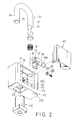
- Figure 2 is an exploded perspective view of a first preferred embodiment of a padlock according to the present invention;
- Figure 3 is a vertical sectional view of the first preferred embodiment when in a locking state;
- Figure 4 is a horizontal sectional view of the first preferred embodiment, taken along line IV-IV in Figure 3;
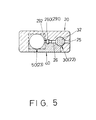
- Figure 5 is another horizontal sectional view of the first preferred embodiment, taken along line V-V in Figure 3;
- Figure 6 is vertical sectional view of the first preferred embodiment, taken along line VI-VI in Figure 3;
- Figure 7 is a vertical sectional view of the first preferred embodiment when in an unlocking state;
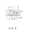
- Figure 8 is a horizontal sectional view of the first preferred embodiment, taken along line VIII-VIII in Figure 7;
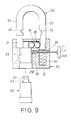
- Figure 9 is a vertical sectional view illustrating how a lock device can be removed from a lock base of the padlock of the first preferred embodiment; and
- Figure 10 is a vertical sectional view illustrating a padlock of a second preferred embodiment according to the present invention.
-
- Referring to Figures 2 and 3, the padlock of the first preferred embodiment according to the present invention is shown to include a
lock base 20, a generallyU-shaped shackle 30, alock device 50, alocking unit 28, and abiasing spring 31. - The
lock base 20 is formed from abody part 200 and acover member 40 which is secured to thebody part 200 at a front opening 27 of the latter, such as by welding. Thelock base 20 is formed as a generally rectangular body with top and bottom sides, and is formed with spaced first and second shackle insertholes shackle insert hole 22 has a length longer than that of the secondshackle insert hole 21. Thelock base 20 is further formed with alock receiving space 23 which extends from the bottom side toward the top side and which is disposed between the first and secondshackle insert holes lock receiving space 23 has a rectangular lower section, and an upper section which is communicated with the secondshackle insert hole 21. Thelock base 20 is further formed with aball chamber 24 which extends transversely between the firstshackle insert hole 22 and the upper section of thelock receiving space 23, and afastener hole 26 which extends between the firstshackle insert hole 22 and thelock receiving space 23 below theball chamber 24. Theball chamber 24 has a circular cross-section and a predetermined length for receiving thelocking unit 28 that consists of a predetermined number ofball members 280 therein. Thefastener hole 26 has a nut-retaining hole portion 260 with a hexagonal cross-section. Thelock base 20 has a surrounding wall between the top and bottom sides and formed with anaccess bore 25 which extends into the firstshackle insert hole 22 and which is aligned with thefastener hole 26. - The
lock device 50 is received in thelock receiving space 23, and has a lower end formed as a rectangular head portion which is retained in the rectangular lower section of thelock receiving space 23. Thelock device 50 is provided with an axiallyrotatable lock core 51 which has aplunger 53 that is disposed in the upper section of thelock receiving space 23. Theplunger 53 is formed with a generallyrectangular latch projection 52. - In this embodiment, the length of the
ball chamber 24 is suitable for receiving alocking unit 28 which includes twoball members 280. Theball members 280 are rollingly disposed in theball chamber 24 adjacent to theplunger 51. - The
shackle 30 includes alonger leg portion 32 which is slidably and rotatably retained in the firstshackle insert hole 22, and ashorter leg portion 34 which is received removably in the secondshackle insert hole 21. Thelonger leg portion 32 has an inner side facing theshorter leg portion 34 and formed with a curvedball retaining groove 33 for engaging one of theball members 280 of thelocking unit 28 that is disposed immediately adjacent to thelonger leg portion 32. Theshorter leg portion 34 has an inner side facing thelonger leg portion 32 and formed with a generally rectangularplunger engaging groove 35 for engaging thelatch projection 52 of theplunger 53. - The biasing
spring 31 is disposed in the firstshackle insert hole 22 below thelonger leg portion 32 for biasing thelonger leg portion 32 upwardly. - With further reference to Figures 5 and 6, the
fastener unit 29 is disposed in thefastener hole 26 of thelock base 20, and includes anut 291 retained in the nut-retaining hole portion 260 and ascrew bolt 292 which extends threadedly through thenut 291 and which has one end abutting against a peripheral portion of thelock device 50 so as to prevent removal of thelock device 50 from thelock receiving space 23. - In assembly, the
fastener unit 29 is placed in thefastener hole 26 of thelock base 20 before thecover member 40 is welded to thebody part 200 of thelock base 20. Then, thebiasing spring 31 is disposed in the firstshackle insert hole 22, and the longer andshorter leg portions shackle insert holes locking unit 28 is disposed in theball chamber 24. The number of theball members 280 required to form thelocking unit 28 depends on the length of theball chamber 24 formed in thelock base 20. In this embodiment, twoball members 280 are required. Finally, thelock device 50 with thelock core 51 mounted thereon is extended into thelock receiving space 23 from the bottom side of thelock base 20. In order to secure thelock device 50 to thelock base 20, atool 100 is extended into thefastener hole 26 via theaccess bore 25 and through the firstshackle insert hole 22 for operating thescrew bolt 292 so that one end of thescrew bolt 292 abuts against thelock device 50 to prevent removal of the latter from thelock receiving space 23. Operation of thescrew bolt 292 by thetool 100 is conducted under the condition that thelonger leg portion 32 is moved upwardly to expose thefastener hole 26. Assembly of the padlock is thus completed. - Referring to Figures 3 and 4, when the padlock is in a locking state, the
latch projection 52 of theplunger 53 of thelock device 50 extends into the secondshackle insert hole 21 to engage theplunger engaging groove 35 in theshorter leg portion 34 of theshackle 30, and one of theball members 280 that is disposed immediately adjacent to thelonger leg portion 32 engages theball retaining groove 33 in thelonger leg portion 32, thereby arresting upward movement of the longer andshorter leg portions shorter leg portion 34 from the secondshackle insert hole 21 is prevented at this time. The biasingspring 31 is compressed under this condition. - Referring to Figures 7 and 8, when the
lock device 50 is operated using the correct key (not shown) to result in axial rotation of thelock core 51 and theplunger 53, thelatch projection 52 is moved away from theshorter leg portion 34 to disengage theplunger engaging groove 35, and the biasingspring 31 expands to move thelonger leg portion 32 upwardly for disengaging theadjacent ball member 280 of the lockingunit 28, thereby permitting removal of theshorter leg portion 34 from the secondshackle insert hole 21 and placing the padlock in an unlocking state. It is noted that, when the padlock is in the unlocking state, theball member 280 that is disposed adjacent to thelonger leg portion 32 can engage a bottom end of the latter to prevent removal of thelonger leg portion 32 from the firstshackle insert hole 22, while permitting axial rotation of thelonger leg portion 32 in the firstshackle insert hole 22. - Referring to Figure 9, the
tool 100 is extendible into thefastener hole 26 via the access bore 25 only when the padlock is in an unlocking state. This is because thefastener hole 26 is blocked by thelonger leg portion 32 to prevent access thereto when the padlock is in the locking state. As such, when it is desired to remove thelock device 50, such as for replacement with a new one, thelock device 50 is first operated using the correct key for disengaging thelonger leg portion 32 from the lockingunit 28 so that thelonger leg portion 32 is moved upwardly by virtue of the biasingspring 31 to expose thefastener hole 26. Thetool 100 is then extended into thefastener hole 26 to operate thescrew bolt 292 so that thescrew bolt 292 is moved away from thelock device 50 to permit removal of thelock device 50 from thelock receiving space 23. After a new lock device is placed in thelock receiving space 23, thescrew bolt 292 is operated using thetool 100 to engage the new lock device. - Referring again to Figure 3, when the padlock is in the locking state, it is noted that the
lock device 50 can be prevented from being removed from thelock receiving space 23 even if thescrew bolt 292 is loosened from thelock device 50 since theplunger 53 of thelock device 50 engages theshorter leg portion 34. - Referring to Figure 10, the padlock of the second preferred embodiment according to the present invention is shown to include a lock base 20' which has a width shorter than that of the
lock base 20 in the previous embodiment. In this situation, the length of the ball chamber 24' is shortened in accordance with the shorter width of the lock base 20', while the size of the lock receiving space is kept identical to that in the previous embodiment. Only oneball member 280 is installed in the ball chamber 24' for engaging the ball retaining groove 33' in the longer leg portion of the shackle 30'. Thelock device 50 in the previous embodiment can be used in the lock base 20' of this embodiment. - According to the present invention, a lock device can be used with lock bases of different widths by modifying the number of ball members that constitute the locking unit to fit the length of the ball chamber. It is not necessary to design and manufacture a different lock device, which is relatively costly, in order to fit a lock base of a different width. The present invention thus results in cost-savings. Moreover, with a replaceable lock device, the padlock of this invention can provide an enhanced anti-theft effect.
Claims (4)
- A padlock includingcharacterized by:a lock base (20) having top and bottom sides and formed with first and second shackle insert holes (22, 21) which extend from the top side toward the bottom side, the first shackle insert hole (22) having a length longer than that of the second shackle insert hole (21), the lock base (20) being further formed with a lock receiving space (23) which extends from the bottom side toward the top side and which is disposed between the first and second shackle insert holes (22, 21),a lock device (50) received in the lock receiving space (23),a shackle (30) having a longer leg portion (32) which is retained slidably and rotatably in the first shackle insert hole (22), and a shorter leg portion (34) which is received removably in the second shackle insert hole (21), anda biasing spring (31) disposed in the first shackle insert hole (22) for biasing the longer leg portion (32) upwardly,the lock receiving space (23) having an upper section communicated with the second shackle insert hole (21), the lock base (20) being further formed with a ball chamber (24) which extends transversely between the first shackle insert hole (22) and the upper section of the lock receiving space (23);the lock device (50) having an axially rotatable key-operated lock core (51) which is provided with a plunger (53) that is disposed in the upper section of the lock receiving space (23), the plunger (53) being formed with a latch projection (52);a locking unit (28) including at least one ball member (280) rollingly disposed in the ball chamber (24) adjacent to the plunger (53);the shorter leg portion (34) being formed with a plunger engaging groove (35) for engaging the latch projection (52) of the plunger (53), the longer leg portion (32) being formed with a ball retaining groove (33) for engaging the locking unit (28);the lock core (51) being rotatable so as to rotate the plunger (53) between a locking position, in which the latch projection (52) of the plunger (53) engages the plunger engaging groove (35) in the shorter leg portion (34) and in which the locking unit (28) engages the ball retaining groove (33) in the longer leg portion (32) to arrest upward movement of the longer and shorter leg portions (32, 34) against action of the biasing spring (31) in order to prevent removal of the shorter leg portion (34) from the second shackle insert hole (21), and an unlocking position, in which the latch projection (52) is disengaged from the plunger engaging groove (35) in the shorter leg portion (34), and the longer leg portion (32) is moved relative to the locking unit (28) due to the action of the biasing spring (31) for disengaging the locking unit (28), thereby permitting removal of the shorter leg portion (34) from the second shackle insert hole (21).
- The padlock according to Claim 1, characterized in that the lock base (20) is further formed with a fastener hole (26) which extends transversely between the first shackle insert hole (22) and the lock receiving space (23) below the ball chamber (24), the lock base (20) having a surrounding wall between the top and bottom sides and formed with an access bore (25) that extends into the first shackle insert hole (22) and that is aligned with the fastener hole (26), a fastener unit (29) being received in the fastener hole (26) and having one end engaging the lock device (50) so as to prevent removal of the lock device (50) from the lock receiving space (23), the fastener unit (29) being operable by means of a tool (100) that extends into the fastener hole (26) via the access bore (25) when the longer leg portion (32) disengages the locking unit (28).
- The padlock according to Claim 2, characterized in that the fastener unit (29) includes a nut (291) disposed within the fastener hole (26), and a screw bolt (292) extending threadedly through the nut (291) and having one end that engages the lock device (50), the screw bolt (292) being operable by means of the tool (100) so that said one end is moved away from the lock device (50) in order to permit removal of the lock device (50) from the lock receiving space (23) when the longer leg portion (32) disengages the locking unit (28).
- The padlock according to Claim 1, characterized in that the locking unit (28) includes more than one ball member (280).
Priority Applications (1)
| Application Number | Priority Date | Filing Date | Title |
|---|---|---|---|
| EP98305394A EP0971087A1 (en) | 1998-07-07 | 1998-07-07 | Padlock |
Applications Claiming Priority (1)
| Application Number | Priority Date | Filing Date | Title |
|---|---|---|---|
| EP98305394A EP0971087A1 (en) | 1998-07-07 | 1998-07-07 | Padlock |
Publications (1)
| Publication Number | Publication Date |
|---|---|
| EP0971087A1 true EP0971087A1 (en) | 2000-01-12 |
Family
ID=8234921
Family Applications (1)
| Application Number | Title | Priority Date | Filing Date |
|---|---|---|---|
| EP98305394A Withdrawn EP0971087A1 (en) | 1998-07-07 | 1998-07-07 | Padlock |
Country Status (1)
| Country | Link |
|---|---|
| EP (1) | EP0971087A1 (en) |
Cited By (4)
| Publication number | Priority date | Publication date | Assignee | Title |
|---|---|---|---|---|
| EP1199426B1 (en) * | 2000-10-17 | 2005-04-27 | Burg-Wächter Kg | Padlock with insert |
| US7040126B2 (en) | 2002-04-09 | 2006-05-09 | Master Lock Company | Discriminating mechanism for a pin tumbler lock |
| CN103317382A (en) * | 2013-06-13 | 2013-09-25 | 杭州电子科技大学 | Automatic pin tumbler separating, direction-selecting and sequencing feed device for assembling padlock |
| EP2868850A1 (en) * | 2013-11-05 | 2015-05-06 | ABUS August Bremicker Söhne KG | Padlock |
Citations (6)
| Publication number | Priority date | Publication date | Assignee | Title |
|---|---|---|---|---|
| US2141748A (en) * | 1936-10-05 | 1938-12-27 | Chicago Lock Co | Padlock |
| US2460615A (en) * | 1945-06-07 | 1949-02-01 | Yale & Towne Mfg Co | Removable core lock |
| US3172279A (en) * | 1962-11-07 | 1965-03-09 | Independent Lock Co | Padlock assembly |
| DE2741718A1 (en) * | 1977-09-16 | 1979-03-29 | Mrt Magnet Regeltechnik Gmbh | Mortice lock with profiled cylinder - held by clamping screw contacting centering seat in lock |
| US4545223A (en) * | 1983-02-07 | 1985-10-08 | Oy Wartsila Ab | Padlock |
| GB2224071A (en) * | 1987-09-10 | 1990-04-25 | Teena Jane Rowlands | Padlock with removable cylinder and re-inforced shackle |
-
1998
- 1998-07-07 EP EP98305394A patent/EP0971087A1/en not_active Withdrawn
Patent Citations (6)
| Publication number | Priority date | Publication date | Assignee | Title |
|---|---|---|---|---|
| US2141748A (en) * | 1936-10-05 | 1938-12-27 | Chicago Lock Co | Padlock |
| US2460615A (en) * | 1945-06-07 | 1949-02-01 | Yale & Towne Mfg Co | Removable core lock |
| US3172279A (en) * | 1962-11-07 | 1965-03-09 | Independent Lock Co | Padlock assembly |
| DE2741718A1 (en) * | 1977-09-16 | 1979-03-29 | Mrt Magnet Regeltechnik Gmbh | Mortice lock with profiled cylinder - held by clamping screw contacting centering seat in lock |
| US4545223A (en) * | 1983-02-07 | 1985-10-08 | Oy Wartsila Ab | Padlock |
| GB2224071A (en) * | 1987-09-10 | 1990-04-25 | Teena Jane Rowlands | Padlock with removable cylinder and re-inforced shackle |
Cited By (5)
| Publication number | Priority date | Publication date | Assignee | Title |
|---|---|---|---|---|
| EP1199426B1 (en) * | 2000-10-17 | 2005-04-27 | Burg-Wächter Kg | Padlock with insert |
| US7040126B2 (en) | 2002-04-09 | 2006-05-09 | Master Lock Company | Discriminating mechanism for a pin tumbler lock |
| CN103317382A (en) * | 2013-06-13 | 2013-09-25 | 杭州电子科技大学 | Automatic pin tumbler separating, direction-selecting and sequencing feed device for assembling padlock |
| CN103317382B (en) * | 2013-06-13 | 2015-09-23 | 杭州电子科技大学 | Pellet for padlock assembling is separated choosing automatically to sequence feeding device |
| EP2868850A1 (en) * | 2013-11-05 | 2015-05-06 | ABUS August Bremicker Söhne KG | Padlock |
Similar Documents
| Publication | Publication Date | Title |
|---|---|---|
| US5896761A (en) | Padlock | |
| US6553801B2 (en) | Impact resistant lock apparatus with anti-theft lock core | |
| US5931030A (en) | Padlock with replaceable key-operated lock core | |
| US7121573B2 (en) | Vehicle accessory mounting system | |
| US6666054B1 (en) | Remote-controlled door lock | |
| JP4657284B2 (en) | Front-mounting lock assembly | |
| JP2008519927A (en) | Re-lockable lock cylinder | |
| US3721112A (en) | Locks | |
| US5720191A (en) | Padlock | |
| WO1995008040A1 (en) | Bolt housing, assembly, and fitted panel | |
| US6367292B1 (en) | Padlock protector | |
| US6644072B1 (en) | Remote-controlled door lock | |
| WO2005019041A2 (en) | Security cover with releasable lock | |
| EP0971087A1 (en) | Padlock | |
| AU757325B2 (en) | Padlock | |
| US5444999A (en) | Gear shift lever lock | |
| US5361613A (en) | Vehicle anti-theft device | |
| US6595032B2 (en) | Lock cylinder-free lock device | |
| US6854306B2 (en) | Self-contained lock assembly | |
| EP1304434B1 (en) | Padlock with a U-shaped lock casing | |
| JP6403826B2 (en) | Keyhole shielding device | |
| JPH0639418Y2 (en) | Lock for vending machine | |
| US20090113958A1 (en) | Automobile steering wheel lock | |
| AU754316B2 (en) | Padlock with replaceable key-operated lock core | |
| CN213269374U (en) | Lock set |
Legal Events
| Date | Code | Title | Description |
|---|---|---|---|
| PUAI | Public reference made under article 153(3) epc to a published international application that has entered the european phase |
Free format text: ORIGINAL CODE: 0009012 |
|
| AK | Designated contracting states |
Kind code of ref document: A1 Designated state(s): AT BE CH DE DK ES FI FR GB GR IE IT LI LU MC NL PT SE |
|
| AX | Request for extension of the european patent |
Free format text: AL;LT;LV;MK;RO;SI |
|
| 17P | Request for examination filed |
Effective date: 20000616 |
|
| AKX | Designation fees paid |
Free format text: AT BE CH DE DK ES FI FR GB GR IE IT LI LU MC NL PT SE |
|
| 17Q | First examination report despatched |
Effective date: 20030805 |
|
| STAA | Information on the status of an ep patent application or granted ep patent |
Free format text: STATUS: THE APPLICATION IS DEEMED TO BE WITHDRAWN |
|
| 18D | Application deemed to be withdrawn |
Effective date: 20060201 |