EP0970335B1 - Insulated shipping container - Google Patents
Insulated shipping container Download PDFInfo
- Publication number
- EP0970335B1 EP0970335B1 EP98913181A EP98913181A EP0970335B1 EP 0970335 B1 EP0970335 B1 EP 0970335B1 EP 98913181 A EP98913181 A EP 98913181A EP 98913181 A EP98913181 A EP 98913181A EP 0970335 B1 EP0970335 B1 EP 0970335B1
- Authority
- EP
- European Patent Office
- Prior art keywords
- insulated
- coolant
- product
- cavity
- shipping container
- Prior art date
- Legal status (The legal status is an assumption and is not a legal conclusion. Google has not performed a legal analysis and makes no representation as to the accuracy of the status listed.)
- Expired - Lifetime
Links
- 239000002826 coolant Substances 0.000 claims abstract description 107
- 229920002635 polyurethane Polymers 0.000 claims abstract description 17
- 239000004814 polyurethane Substances 0.000 claims abstract description 17
- 238000002347 injection Methods 0.000 claims abstract description 6
- 239000007924 injection Substances 0.000 claims abstract description 6
- CURLTUGMZLYLDI-UHFFFAOYSA-N Carbon dioxide Chemical compound O=C=O CURLTUGMZLYLDI-UHFFFAOYSA-N 0.000 claims description 10
- 235000011089 carbon dioxide Nutrition 0.000 claims description 10
- 210000002105 tongue Anatomy 0.000 claims description 5
- 239000012530 fluid Substances 0.000 claims description 2
- 239000002985 plastic film Substances 0.000 abstract 1
- 229920006255 plastic film Polymers 0.000 abstract 1
- 239000004794 expanded polystyrene Substances 0.000 description 8
- 239000011810 insulating material Substances 0.000 description 6
- 238000009413 insulation Methods 0.000 description 6
- 239000006260 foam Substances 0.000 description 5
- 238000007789 sealing Methods 0.000 description 5
- 239000010408 film Substances 0.000 description 4
- 238000003780 insertion Methods 0.000 description 3
- 230000037431 insertion Effects 0.000 description 3
- 239000000463 material Substances 0.000 description 3
- 238000001816 cooling Methods 0.000 description 2
- 239000011888 foil Substances 0.000 description 2
- 238000001746 injection moulding Methods 0.000 description 2
- 239000007788 liquid Substances 0.000 description 2
- 238000002844 melting Methods 0.000 description 2
- 230000008018 melting Effects 0.000 description 2
- 238000012986 modification Methods 0.000 description 2
- 230000004048 modification Effects 0.000 description 2
- 238000000465 moulding Methods 0.000 description 2
- 229920003023 plastic Polymers 0.000 description 2
- 239000004033 plastic Substances 0.000 description 2
- 229920000728 polyester Polymers 0.000 description 2
- 238000005057 refrigeration Methods 0.000 description 2
- 240000002129 Malva sylvestris Species 0.000 description 1
- 235000006770 Malva sylvestris Nutrition 0.000 description 1
- 239000004698 Polyethylene Substances 0.000 description 1
- 239000004721 Polyphenylene oxide Substances 0.000 description 1
- 229920005830 Polyurethane Foam Polymers 0.000 description 1
- 239000000853 adhesive Substances 0.000 description 1
- 230000001070 adhesive effect Effects 0.000 description 1
- 230000002411 adverse Effects 0.000 description 1
- 235000013361 beverage Nutrition 0.000 description 1
- 239000008280 blood Substances 0.000 description 1
- 210000004369 blood Anatomy 0.000 description 1
- 235000012970 cakes Nutrition 0.000 description 1
- 235000013351 cheese Nutrition 0.000 description 1
- 238000007796 conventional method Methods 0.000 description 1
- 239000003814 drug Substances 0.000 description 1
- 230000000694 effects Effects 0.000 description 1
- 238000007710 freezing Methods 0.000 description 1
- 230000008014 freezing Effects 0.000 description 1
- 235000013611 frozen food Nutrition 0.000 description 1
- 238000010438 heat treatment Methods 0.000 description 1
- 238000004519 manufacturing process Methods 0.000 description 1
- 229940127554 medical product Drugs 0.000 description 1
- 239000000155 melt Substances 0.000 description 1
- 238000000034 method Methods 0.000 description 1
- 238000004806 packaging method and process Methods 0.000 description 1
- 235000014594 pastries Nutrition 0.000 description 1
- 239000000825 pharmaceutical preparation Substances 0.000 description 1
- 229940127557 pharmaceutical product Drugs 0.000 description 1
- 229920000570 polyether Polymers 0.000 description 1
- -1 polyethylene Polymers 0.000 description 1
- 229920000573 polyethylene Polymers 0.000 description 1
- 239000011496 polyurethane foam Substances 0.000 description 1
- 238000004064 recycling Methods 0.000 description 1
- 239000003507 refrigerant Substances 0.000 description 1
- 235000013580 sausages Nutrition 0.000 description 1
- 239000000565 sealant Substances 0.000 description 1
- 238000004904 shortening Methods 0.000 description 1
- 239000010409 thin film Substances 0.000 description 1
Images

Classifications
-
- F—MECHANICAL ENGINEERING; LIGHTING; HEATING; WEAPONS; BLASTING
- F25—REFRIGERATION OR COOLING; COMBINED HEATING AND REFRIGERATION SYSTEMS; HEAT PUMP SYSTEMS; MANUFACTURE OR STORAGE OF ICE; LIQUEFACTION SOLIDIFICATION OF GASES
- F25D—REFRIGERATORS; COLD ROOMS; ICE-BOXES; COOLING OR FREEZING APPARATUS NOT OTHERWISE PROVIDED FOR
- F25D3/00—Devices using other cold materials; Devices using cold-storage bodies
- F25D3/12—Devices using other cold materials; Devices using cold-storage bodies using solidified gases, e.g. carbon-dioxide snow
- F25D3/14—Devices using other cold materials; Devices using cold-storage bodies using solidified gases, e.g. carbon-dioxide snow portable, i.e. adapted to be carried personally
-
- B—PERFORMING OPERATIONS; TRANSPORTING
- B65—CONVEYING; PACKING; STORING; HANDLING THIN OR FILAMENTARY MATERIAL
- B65D—CONTAINERS FOR STORAGE OR TRANSPORT OF ARTICLES OR MATERIALS, e.g. BAGS, BARRELS, BOTTLES, BOXES, CANS, CARTONS, CRATES, DRUMS, JARS, TANKS, HOPPERS, FORWARDING CONTAINERS; ACCESSORIES, CLOSURES, OR FITTINGS THEREFOR; PACKAGING ELEMENTS; PACKAGES
- B65D81/00—Containers, packaging elements, or packages, for contents presenting particular transport or storage problems, or adapted to be used for non-packaging purposes after removal of contents
- B65D81/38—Containers, packaging elements, or packages, for contents presenting particular transport or storage problems, or adapted to be used for non-packaging purposes after removal of contents with thermal insulation
- B65D81/3848—Containers, packaging elements, or packages, for contents presenting particular transport or storage problems, or adapted to be used for non-packaging purposes after removal of contents with thermal insulation semi-rigid container folded up from one or more blanks
- B65D81/3862—Containers, packaging elements, or packages, for contents presenting particular transport or storage problems, or adapted to be used for non-packaging purposes after removal of contents with thermal insulation semi-rigid container folded up from one or more blanks with a foam formed container located inside a folded box
-
- F—MECHANICAL ENGINEERING; LIGHTING; HEATING; WEAPONS; BLASTING
- F25—REFRIGERATION OR COOLING; COMBINED HEATING AND REFRIGERATION SYSTEMS; HEAT PUMP SYSTEMS; MANUFACTURE OR STORAGE OF ICE; LIQUEFACTION SOLIDIFICATION OF GASES
- F25D—REFRIGERATORS; COLD ROOMS; ICE-BOXES; COOLING OR FREEZING APPARATUS NOT OTHERWISE PROVIDED FOR
- F25D2303/00—Details of devices using other cold materials; Details of devices using cold-storage bodies
- F25D2303/08—Devices using cold storage material, i.e. ice or other freezable liquid
- F25D2303/084—Position of the cold storage material in relationship to a product to be cooled
- F25D2303/0843—Position of the cold storage material in relationship to a product to be cooled on the side of the product
-
- F—MECHANICAL ENGINEERING; LIGHTING; HEATING; WEAPONS; BLASTING
- F25—REFRIGERATION OR COOLING; COMBINED HEATING AND REFRIGERATION SYSTEMS; HEAT PUMP SYSTEMS; MANUFACTURE OR STORAGE OF ICE; LIQUEFACTION SOLIDIFICATION OF GASES
- F25D—REFRIGERATORS; COLD ROOMS; ICE-BOXES; COOLING OR FREEZING APPARATUS NOT OTHERWISE PROVIDED FOR
- F25D2331/00—Details or arrangements of other cooling or freezing apparatus not provided for in other groups of this subclass
- F25D2331/80—Type of cooled receptacles
- F25D2331/804—Boxes
Definitions
- the present invention relates generally to shipping containers, and more particularly to an insulated shipping container having a plurality of cavities therein for holding a temperature sensitive product and coolant in a predetermined relationship to maintain a refrigerated condition for an extended period of time.
- EPS expanded polystyrene
- Containers including EPS are often provided in a modular form. Individual panels of EPS insulation, possibly wrapped in foil or the like, are preformed using conventional methods, typically with beveled edges. The panels are then inserted into a conventional shipping carton against each wall to create an insulated cavity within the carton, the beveled edges of adjacent panels forming seams along the corners of the carton. A product is placed in the cavity and a plug, such as a thick polyether or polyester foam pad, is placed over the top of the product before the carton is closed and prepared for shipping. In many cases, a coolant, such as packaged ice, gel packs, or loose dry ice, is placed around the product in the cavity to refrigerate the product during shipping.
- a coolant such as packaged ice, gel packs, or loose dry ice
- an insulated body may be injection molded from expanded polystyrene, forming a cavity therein and having an open top to access the cavity.
- a product is placed in the cavity, typically along with coolant, and a cover is placed over the open end, such as the foam plug described above or a cover formed from EPS.
- EPS polyurethane
- a cardboard carton having a box liner therein, defining a desired insulation space between the liner and the carton.
- Polyurethane foam is injected into the insulation space, substantially filling the space and generally adhering to the carton and the liner.
- the interior of the box liner provides a cavity into which a product and coolant may be placed.
- a foam plug may be placed over the product, or a lid may be formed from polyurethane, typically having a flat or possibly an inverted top-hat shape.
- insulated shipping containers have many problems, particularly when shipping temperature sensitive products for extended periods of time, such as when products are shipped internationally.
- These containers, especially the modular liner systems often include a number of seams in the insulating material through which air can enter and heat the cavity in the carton.
- the cavity often includes air spaces around the product and coolant which can facilitate convection, especially if the insulating material includes leaking seams. These conditions may accelerate the melting of the coolant, consequently shortening the time that the container can maintain a refrigerated condition.
- the cover or plug may be formed from a different material, such as polyester foam, which may have a thermal resistance substantially lower than the body itself, and thus may compromise the performance of the container.
- the product and coolant are typically placed together within the cavity in the carton, which may have several adverse effects.
- a coolant such as loose blocks of dry ice
- the coolant may shift in the cavity during shipping, especially as it melts and shrinks in size, inadvertently contacting the product.
- melted coolant may leak from its container, possibly creating a mess within the cavity or even contaminating the product being shipped.
- polyurethane containers may also create a disposal problem.
- polyurethane When polyurethane is injected into a carton, it generally adheres substantially to the walls of the carton. Thus, the cardboard and insulation components may have to be disposed of together, preventing recycling of the container.
- DE-A-25 05 203 discloses a container including outer and inner side walls and a bottom wall, the side walls defining an annular compartment surrounding a central compartment. Hot liquid may be introduced into the annular compartment and foodstuffs may be stored in the central compartment, intended to be warmed by the hot liquid.
- the container includes a lid, which includes an extension which engages the annular compartment.
- FR-A-2 649 381 discloses a large rectangular product compartment into which a number of articles may be indiscriminately placed. A number of narrow cylindrical passages are provided in the gas permeable side walls of the container for receiving refrigerant.
- an insulated container which includes a single coolant compartment adjacent a plurality of product sockets.
- the interior walls of the container do not extend completely to the top of the container, and the container includes a flat lid which may be received on the open top.
- DE-U-296 04 325 discloses a box having a single large compartment into which a number of foodstuffs, such as cakes, pastries, sausages, cheeses, beverages and the like may be placed.
- the walls have materially reduced regions to accommodate cooling or heating elements, which may be locked in place with retaining elements, such as lock washers, to prevent the cooling elements from coming loose.
- the boxes are stacked on top of one another, and a cover may be provided for the uppermost box.
- a principal object of the present invention is to provide an improved shipping container in which seams and air spaces are substantially minimized, thereby maximizing the period of time during which a product being shipped may be refrigerated.
- the present invention is directed generally to an improved insulated shipping container for shipping a temperature sensitive product in a refrigerated condition for an extended period of time.
- the container includes an insulated body having a cavity in it for holding a product being shipped, and includes one or more cavities for holding coolant in a predetermined relationship to the product cavity. An open end of the body provides access to the cavities, allowing a product and coolant to be placed in the respective cavities.
- the container also includes an insulated cover to close the open end of the body once the product and coolant are placed therein.
- the cover includes insulated blocks extending from the cover that slide into and substantially fill any remaining space in the cavities when the cover is placed over the open end.
- the insulated body and cover are formed from a substantially rigid insulating material having a relatively low thermal conductivity and being relatively light weight.
- the insulated body and cover are formed from injection molded rigid polyurethane, wrapped in a film of plastic or the like, allowing the body and cover to be removably inserted into a conventional cardboard shipping carton.
- the shipping container includes a substantially rectangular insulated body having four side walls, a bottom wall, and an open top defining a product cavity, the walls having a predetermined thickness to thermally insulate the product cavity.
- the product cavity preferably has a shape that allows a product to be securely held during shipping and/or handling, and that substantially minimizes air spaces around the product.
- One or more of the side walls include a coolant cavity therein, generally extending adjacent the product cavity from the open top towards the bottom wall.
- a coolant cavity therein, generally extending adjacent the product cavity from the open top towards the bottom wall.
- two opposite side walls each include a coolant cavity, and more preferably, all four side walls have coolant cavities in them adjacent the product cavity.
- the coolant cavities have a shape for receiving a conventional coolant, such as packaged ice, gel packs, or blocks of dry ice, preferably having a shape to securely hold the coolant in position and to minimize remaining air spaces around the coolant.
- the container also includes an insulated cover for closing and substantially sealing the open end of the insulated body, preferably by cooperating tongues and grooves integrally formed around the perimeter of the cover and the body.
- the cover also includes one or more insulated blocks extending from and preferably integrally molded to the cover.
- the blocks have a shape and location on the cover allowing them to be inserted into the coolant cavities when the cover is placed over the open end of the insulated body.
- the blocks slidably engage the walls of the coolant cavities and abut the coolant placed therein, thereby substantially minimizing any remaining air spaces above the coolant and substantially sealing the cavities.
- the cover may include an insulated block for insertion into the product cavity to similarly minimize air space remaining above the product placed therein.
- the insulated blocks, together with the shaped cavities substantially reduce convection and leakage within the container, and thereby may substantially extend the effective time period that a product may be shipped in a refrigerated condition using the container.
- the insulated body and cover may be used to ship temperature sensitive products without additional packaging
- the body is preferably inserted into a conventional cardboard shipping carton, such that the outer surfaces of the body substantially engage the inside walls of the carton.
- a product and coolant are placed in the body, the cover is placed over the open end, substantially sealing the body.
- the carton may then be closed and prepared for shipping in a conventional manner.
- the coolant cavities in the insulated body are substantially isolated from the product cavity.
- this orientation allows a product to be shipped in a refrigerated, but not frozen, condition, the portion of the side walls between the coolant and product cavities partially insulating the product from the temperatures of the coolant.
- a passage extends between each coolant cavity and the product cavity, preferably having a shape that allows the walls of the coolant cavity to securely hold the coolant therein, yet place the coolant in close proximity to the product within the product cavity.
- This orientation exposes the product more directly to the temperature of the coolant, thereby maintaining the product in a substantially frozen condition. For example, if dry ice is placed in the coolant cavity, it may be possible to freeze a product being shipped in the container at temperatures of around -60° Celsius or less for an extended time.
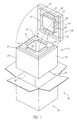
- FIGS. 1-5 show a first preferred embodiment of an insulated shipping container 10 in accordance with the present invention.
- the container 10 generally includes a substantially rectangular insulated body 12, an insulated cover 40, and a shipping carton 60.
- the insulated body 12 has four side walls 14, a bottom wall 16 and an open top 18 defining a product cavity 22, the walls 14 and 16 having a predetermined thickness to thermally insulate the cavity 22.
- the product cavity 22 preferably has a shape that allows a product (not shown) to be placed in the body 12, the inner surfaces 20 of the side walls 14 preferably securely holding the product during shipping and/or handling, and substantially minimizing air spaces around the product.
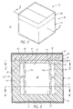
- Each of the four side walls 14 includes a coolant cavity 24 therein, generally extending adjacent the product cavity 22 from the open top 18 towards the bottom wall 16, as shown in FIGS. 3 and 4.
- a coolant cavity 24 therein, generally extending adjacent the product cavity 22 from the open top 18 towards the bottom wall 16, as shown in FIGS. 3 and 4.
- only two opposite side walls 14 may include a coolant cavity 24.
- the inner surfaces 26 of the coolant cavities 24 have a shape adapted to receive a conventional coolant product (not shown), such as packaged ice, gel packs or other containers of frozen fluid, or loose blocks of dry ice, the inner surfaces 26 having a shape to securely hold the coolant in position and to minimize remaining air spaces around the coolant.
- dry ice may be available in 12,7 cm x 12,7 cm x 3,8 cm (5 inch x 5 inch x 1-1/2 inch) blocks, and so for shipping applications in which dry ice is used, the coolant cavities 24 may have width and height dimensions that are multiples of 12,7 cm (5 inches), thereby allowing them to securely hold such blocks of dry ice and substantially minimize voids or air spaces between the blocks.
- the insulated cover 40 has a substantially flat outer surface 41 and an inner surface 43 designed to close and substantially seal the open end 18 of the insulated body 12, for example by using cooperating tongues and grooves.
- the cover 40 includes a tongue 46 extending from and preferably integrally molded around the perimeter of the inner surface 43, while the body 12 includes a similarly shaped groove 32 extending around the perimeter of the open end 18.
- the tongue 46 and groove 32 sealably engage one another, thereby substantially minimizing air leaking between the cavities 22 and 24 in the body 12 and the exterior of the container 10.
- the cover 40 also includes four insulated blocks or prongs 42 extending from and preferably integrally molded to its inner surface 43.
- the blocks 42 correspond to respective coolant cavities 24 and have a shape and location on the cover 40 allowing them to be inserted into the coolant cavities 24 when the cover 40 is placed over the open end 18 of the body 12.
- the outer surfaces 44 of the blocks 42 slidably engage the inner surfaces 26 of the coolant cavities 24, substantially sealing the cavities 24.
- the blocks 42 have a predetermined height, whereby the blocks 42 substantially engage or abut the top of the coolant (not shown) placed in the cavities 24, thereby holding the coolant in place during shipping, and substantially minimizing any remaining air space above the coolant when the cover 40 is in place.
- the coolant may extend from the bottom of the cavity 24 to the top thereof and engage surface 45 of the block 42 when the cover 40 is on the body 12.
- the cover 40 includes another insulated block 48 for insertion into the product cavity 22.
- the outer surfaces 50 of the block 48 slidably engage the inner walls 20 of the product cavity 22 to substantially seal the cavity 22 when the cover 40 is placed over the open end 18.
- the block 48 also has a predetermined height to substantially engage or abut the top of the product (not shown) placed in the cavity 22, holding it in place during shipping and substantially minimizing the air space remaining above the product.
- the insulated body 12 Prior to use, the insulated body 12 is preferably inserted into a conventional cardboard shipping carton 60, the outer surfaces 28 of the insulated body 12 substantially engaging the inside of the walls 62 of the carton 60, and the open end 18 of the body 12 corresponding to the open end 64 of the carton 60.
- the insulated cover 40 is placed over the open end 18, substantially sealing the insulated body 12.
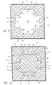
- the carton 60 may then be closed and prepared for shipping in a conventional manner, as shown in FIG. 2.
- the container 10 includes coolant cavities 24 in the insulated body 12 that are substantially isolated from the product cavity 22.
- this orientation is preferred for shipping a product under refrigerated, but not frozen, conditions.
- the portions 14a of the side walls 14 between the coolant cavities 24 and the product cavity 24 partially insulate the product from the temperatures of the coolant, thereby protecting the product from being frozen as it would if in more direct contact with the coolant.
- the blocks 42 and 48 substantially seal the cavities 24 and 22 respectively. This substantially eliminates the chance of coolant migrating during shipping and/or handling from the coolant cavities 24 to the product cavity 22 where it may contact and freeze the product.
- the blocks 42 and 48 are important features of containers in accordance with the present invention for other reasons as well.
- the blocks 42 and 48 substantially abut the coolant and product respectively, substantially minimizing undesired movement during shipping and/or handling of the container 10.
- the blocks 42 substantially retain melted or leaking coolant within the coolant cavities 24, substantially preventing it from entering the product cavity 22 where it may possibly contaminate the product therein.
- the blocks 42 and 48 substantially fill any remaining air spaces after the coolant and product are placed in the respective cavities 24 and 22, and help substantially seal the body 12 and the cover 40. Air spaces within the cavities may accelerate the melting of the coolant, and substantially reduce the duration of effective refrigeration of the product, particularly if seams allow air to leak into the cavities.
- the blocks 42 and 44 substantially eliminate these undesired conditions, thereby substantially extending the effective period of refrigeration for the container 10.
- the insulated body 12 and cover 40 are formed from a substantially rigid insulating material having a relatively low thermal conductivity and being relatively light weight, such as expanded polystyrene, polyurethane, rigid polyurethane, or other foam insulation products.
- the insulated body 12 and cover 40 are formed from rigid polyurethane, formed using conventional injection molding processes that should be familiar to those skilled in the art.
- the insulated body 12 and cover 40 are preferably covered by a thin film (not shown) during manufacturing to prevent the polyurethane from adhering substantially to the carton 60.
- the film may include a thin plastic or foil liner, such as polyethylene, that are laid up in the molding tools used to form the body 12 and the cover 40.
- the polyurethane cures and adheres to the film, rather than to the tool, facilitating removal.
- the film also facilitates insertion and removal of the body 12 and cover 40 from the carton 60. This allows the materials of the shipping container 10 to be more easily separated and recycled after use.
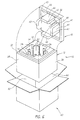
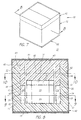
- FIGS. 6-10 a second preferred embodiment of an insulated shipping container 10 in accordance with the present invention is shown. Similar to the previous embodiment, the container includes an insulated body 12, an insulated cover 40, and a shipping carton 60.
- the body 12 has a product cavity 22 defined by the side walls 14 and the bottom wall 16 thereof.
- Four coolant cavities 24 are located adjacent the product cavity 22 and extend from the open end 18 of the body 12 towards the bottom wall 16.
- a passage 34 extends through a portion 14a of the side walls 14 between each coolant cavity 24 and the product cavity 22.
- the passages 34 have a shape that allows the inner surfaces 26 of the coolant cavities 24 to securely hold the coolant 82 (shown in phantom) therein, yet place the coolant 82 in close proximity to the product 80 (shown in phantom) within the product cavity 22.
- This orientation exposes the product 80 more directly to the temperatures of the coolant 82, thereby allowing the product 80 to be maintained in a substantially frozen condition.
- the insulated product block 48 may have a reduced height, thereby allowing an additional coolant 82 to be placed directly on top of the product 80, as shown in FIG. 8. For example, if dry ice is placed in the coolant cavities 24 and on top of the product 80, it may be possible to freeze the product 80 at temperatures of about -60° Celsius or less for an extended time.
- the embodiments described are only exemplary of the possible configurations of insulated shipping containers in accordance with the present invention.
- the flexibility of the injection molding process allows the configuration of the insulated body and the corresponding cover to be easily changed to accommodate a variety of desired shipping conditions within the product cavity.
- the side walls of the insulated body may include any number of coolant cavities placed in a predetermined relationship to the product cavity, with or without passages communicating between the cavities.
- embodiments including a fixed number of coolant cavities may have one or more coolant cavities filled with polyurethane plugs when only some of the those cavities (e.g. two) are required to hold coolant to maintain a desired shipping condition.
- the plugs should have a shape similar to the coolant typically received in the cavities being plugged, thereby substantially eliminating any undesired air space within the body.
- the side walls may also have a variety of thicknesses to provide a predetermined thermal insulation for the container as a whole, and/or to fit into a variety of commercially available cartons.
- the thickness of the portions of the side walls between the coolant cavities and the product cavity may be varied to adjust the temperature to which the product cavity and product therein are exposed.
- the shape and size of the product cavity may be adapted to accommodate a variety of products, possibly forming a plurality of product cavities in the insulated body for shipping multiple products simultaneously.
- containers in accordance with the present invention may be used to safely ship a number of products in which a desired refrigerated or frozen condition is to be maintained for an extended period of time, such as pharmaceuticals, biotechnology products, blood or tissue, cryogenic products, frozen foods, adhesives or sealants, and other similar products.
Abstract
Description
Claims (16)
- An insulated shipping container (10) for transporting a temperature sensitive product, the container (10) comprising :an insulated body (12) having a product cavity (22) therein and an open end (18) for accessing the product cavity (22), the product cavity (22) having a predetermined shape for securely receiving a similarly shaped product to be transported therein;an array of coolant cavities (24) in the insulated body (12) accessible from the open end (18), and being located adjacent the product cavity (22) and having a predetermined spatial relationship with the product cavity (22), each coolant cavity (24) having a predetermined shape for receiving a similarly shaped coolant therein;coolant receivable in the array of coolant cavities (24), the coolant having a shape similar to the respective coolant cavity (24) into which the coolant is received for substantially minimizing air spaces within the array of coolant cavities (24); andan insulated cover (40) adapted to engage the open end (18) of the insulated body (12), the insulated cover (40) including an array of insulated coolant blocks (42) extending therefrom, each insulated coolant block (42) slidably engaging a respective coolant cavity (24) when the insulated cover (40) engages the open end (18), thereby substantially filling a remaining air space within the respective coolant cavity (24) after the coolant is received therein;whereby a product received in the product cavity (22) is subjected to a predetermined refrigerated condition when coolant is received in the array of coolant cavities (24) and the insulated cover (40) substantially engages the open end (18) of the insulated body (12).
- The insulated shipping container of claim 1, wherein the insulated body (12) includes a passage (34) communicating between the product cavity (22) and one or more coolant cavities (24).
- The insulated shipping container of claim 1, further comprising a removable panel insertable into the passage (34) for selectively providing access between the product cavity (22) and the respective coolant cavity (24).
- The insulated shipping container of claim 1, wherein each coolant cavity (24) is substantially isolated from the product cavity (22), thereby partially insulating the product held in the product cavity (22) from the coolant received in each coolant cavity (24).
- The insulated shipping container of claim 1, wherein the insulated body (12) and the insulated cover (40) include cooperating tongues (46) and grooves (32) adapted to substantially seal the container (10) when the insulated cover (40) engages the open end (18) of the insulated body (12).
- The insulated shipping container of claim 1, wherein the insulated cover (40) includes an insulated product block (48) extending therefrom, the insulated product block (48) being adapted to slidably engage the product cavity (22) when the insulated cover (40) engages the open end (18), thereby substantially filling a remaining air space within the product cavity (22) after a product is received therein.
- The insulated shipping container of claim 1, wherein the insulated body (12) comprises injection molded polyurethane.
- The insulated shipping container of claim 1, wherein the insulated cover (40) comprises injection molded polyurethane.
- The insulated shipping container of claim 1, further comprising a shipping carton (60) into which the insulated body (12) is received.
- The insulated shipping container of claim 9, wherein the insulated body (12) comprises injection molded polyurethane wrapped in a film, the film allowing the insulated body (12) to be removably inserted into the shipping carton (60).
- The insulated shipping container of claims 1, wherein the insulated body (12) comprises a substantially rectangular body comprising four side walls (14) and a bottom wall (16) defining the product cavity (22) therein.
- The insulated shipping container of claim 11, wherein the array of coolant cavities (24) comprises a coolant cavity disposed in two opposite side walls (14).
- The insulated shipping container of claim 11, wherein the array of coolant cavities (24) comprises a similarly shaped coolant cavity in each of the four side walls (14).
- The insulated shipping container of claim 11, wherein each of the coolant cavities (24) extends from the open top (18) of the insulated body (12) towards the bottom wall (16) thereof substantially parallel to the product cavity (22).
- The insulated shipping container of claim 1, further comprising a temperature sensitive product received in the product cavity (22), the insulated body (12) comprising a plurality of walls (14,16) defining the product cavity (22), the plurality of walls (14,16) having a predetermined configuration for substantially engaging the product received in the product cavity (22), thereby substantially minimizing air spaces around the product.
- The insulated shipping container of claim 1, wherein the coolant is selected from the group consisting of a gel pack, a block of dry ice, packaged ice, and a container of frozen fluid.
Applications Claiming Priority (3)
| Application Number | Priority Date | Filing Date | Title |
|---|---|---|---|
| US826275 | 1997-03-27 | ||
| US08/826,275 US5924302A (en) | 1997-03-27 | 1997-03-27 | Insulated shipping container |
| PCT/US1998/006040 WO1998043028A1 (en) | 1997-03-27 | 1998-03-25 | Improved insulated shipping container |
Publications (2)
| Publication Number | Publication Date |
|---|---|
| EP0970335A1 EP0970335A1 (en) | 2000-01-12 |
| EP0970335B1 true EP0970335B1 (en) | 2002-06-05 |
Family
ID=25246130
Family Applications (1)
| Application Number | Title | Priority Date | Filing Date |
|---|---|---|---|
| EP98913181A Expired - Lifetime EP0970335B1 (en) | 1997-03-27 | 1998-03-25 | Insulated shipping container |
Country Status (14)
| Country | Link |
|---|---|
| US (1) | US5924302A (en) |
| EP (1) | EP0970335B1 (en) |
| JP (1) | JP2001519020A (en) |
| CN (1) | CN1139772C (en) |
| AT (1) | ATE218694T1 (en) |
| AU (1) | AU724209B2 (en) |
| BR (1) | BR9807891A (en) |
| CA (1) | CA2284291C (en) |
| DE (1) | DE69805784T2 (en) |
| ES (1) | ES2178191T3 (en) |
| HK (1) | HK1024945A1 (en) |
| NZ (1) | NZ337939A (en) |
| RU (1) | RU2192589C2 (en) |
| WO (1) | WO1998043028A1 (en) |
Families Citing this family (101)
| Publication number | Priority date | Publication date | Assignee | Title |
|---|---|---|---|---|
| US6619500B1 (en) | 1996-04-16 | 2003-09-16 | Gary W. Lantz | Compartmentalized insulated shipping container |
| AU4457797A (en) * | 1996-08-30 | 1998-03-19 | Octrooibureau Kisch N.V. | Container for a vial or ampoule |
| US6055825A (en) * | 1998-03-18 | 2000-05-02 | Choy; Anthony | Insulated shipping container |
| US6209343B1 (en) * | 1998-09-29 | 2001-04-03 | Life Science Holdings, Inc. | Portable apparatus for storing and/or transporting biological samples, tissues and/or organs |
| US6067810A (en) | 1998-12-28 | 2000-05-30 | Decision Point Marketing, Inc. | Chilled item server |
| US6370885B1 (en) | 1998-12-28 | 2002-04-16 | Decision Point Marketing, Inc. | Point-of-sale chilled product housing |
| ES2166262B1 (en) * | 1999-05-28 | 2003-06-16 | Garcia Ana Tabuenca | PACKING SYSTEM FOR DELICATE GOODS. |
| IT1309890B1 (en) * | 1999-07-30 | 2002-02-05 | Saldogas S R L | ISOTHERMAL CONTAINERS FOR THE TRANSPORT OF HEAT-PERABLE PRODUCTS EQUIPPED WITH APPROPRIATE COMPARTMENTS TO STORE DRY ICE AND OTHER ELEMENTS |
| US6296134B1 (en) | 1999-11-05 | 2001-10-02 | Salvatore J. Cardinale | Insulated water-tight container |
| AU2216301A (en) | 2000-01-04 | 2001-07-16 | Thermokeep Ltd. | Temperature controlling apparatus and method |
| US6325281B1 (en) | 2000-03-30 | 2001-12-04 | Polyfoam Packers Corporation | Thermally insulating shipping system |
| AU2001271859A1 (en) * | 2000-07-05 | 2002-01-14 | Kodiak Technologies, Inc. | Method for shipping temperature-sensitive goods |
| DE10043508A1 (en) * | 2000-09-01 | 2002-03-14 | Linde Gas Ag | Container with a cooling module |
| DE20018635U1 (en) * | 2000-10-31 | 2001-03-01 | Dade Behring Marburg Gmbh | Insulated container |
| US6415623B1 (en) * | 2001-01-05 | 2002-07-09 | Cold Sell Systems, Llc | Point of sale product chiller |
| US6519968B1 (en) * | 2001-05-09 | 2003-02-18 | Loctite Corporation | Shipping container for exothermic material |
| US6688132B2 (en) | 2001-06-06 | 2004-02-10 | Nanopore, Inc. | Cooling device and temperature-controlled shipping container using same |
| US6584797B1 (en) | 2001-06-06 | 2003-07-01 | Nanopore, Inc. | Temperature-controlled shipping container and method for using same |
| DE10219312A1 (en) * | 2002-04-30 | 2003-11-20 | Biotissue Technologies Ag | Transport container for biological material |
| US7500593B2 (en) * | 2002-10-23 | 2009-03-10 | Minnesota Thermal Science, Llc | Container having passive controlled temperature interior, and method of construction |
| US7422143B2 (en) * | 2002-10-23 | 2008-09-09 | Minnesota Thermal Science, Llc | Container having passive controlled temperature interior |
| US7257963B2 (en) * | 2003-05-19 | 2007-08-21 | Minnesota Thermal Science, Llc | Thermal insert for container having a passive controlled temperature interior |
| DE10322764A1 (en) | 2003-05-19 | 2004-12-30 | Va-Q-Tec Ag | Containers with vacuum insulation and melt storage materials |
| BRPI0412300A (en) * | 2003-07-07 | 2006-06-13 | Rodney M Derifield | insulated shipping containers |
| TW200522930A (en) * | 2004-01-12 | 2005-07-16 | Entropy Solutions | A passive portable blood storage system |
| US7328583B2 (en) * | 2004-01-12 | 2008-02-12 | Entropy Solutions, Inc. | Thermally stable containment device and methods |
| WO2005082047A2 (en) * | 2004-02-20 | 2005-09-09 | Aragon Daniel M | Temperature controlled container |
| US7260956B1 (en) * | 2004-06-25 | 2007-08-28 | The University Of Wyoming Research Corporation | System for maintaining materials at freezer temperatures for shipping |
| ES2261023B1 (en) * | 2004-07-27 | 2007-12-16 | Jose Antonio Pelaez Montilla | PROCEDURE FOR THE CONSTRUCTION OF BEES BY INJECTION OR PROJECTION OF POLYURETHANE FOAM. |
| US7681405B2 (en) * | 2005-04-14 | 2010-03-23 | Alton Williams | Insulated shipping container systems and methods thereof |
| US10457469B2 (en) | 2005-04-14 | 2019-10-29 | James William Howard TUMBER | Insulated shipping container having at least one spacer for improving airflow within the container |
| ITMI20051287A1 (en) * | 2005-07-08 | 2007-01-09 | Deles Imballaggi Speciali S R L | THERMO INSULATING INTERCHANGE FOR PACKAGING |
| US20070084232A1 (en) * | 2005-10-19 | 2007-04-19 | Whewell Robert E Jr | Dry ice delivery method that controls the temperature of cooling compartment(s) |
| US8424319B2 (en) * | 2005-10-19 | 2013-04-23 | Robert E. Whewell, JR. | Temperature regulation apparatus and method |
| US20070186577A1 (en) * | 2006-02-16 | 2007-08-16 | Michael Goncharko | Passively temperature-regulated shipping container suitable for biological, pharmaceutical materials or food products |
| WO2007103267A2 (en) | 2006-03-02 | 2007-09-13 | Cold Chain Technologies, Inc. | Insulated shipping container and method of making the same |
| US20070271947A1 (en) * | 2006-05-24 | 2007-11-29 | Tegrant Corporation | Insulated container |
| US20070277546A1 (en) * | 2006-05-30 | 2007-12-06 | Blower-Demsey Corp.Dba Pak Wwst Paper And Packaging | Temperature controlled shipping container |
| US7624873B2 (en) * | 2006-06-20 | 2009-12-01 | Tennant Packaging Corporation | Diagnostic specimen shipping kit |
| US7721566B1 (en) | 2006-08-14 | 2010-05-25 | Minnesota Thermal Science, Llc | Collapsible interconnected panels of phase change material |
| US20080135564A1 (en) * | 2006-12-12 | 2008-06-12 | Benjamin Romero | Container for shipping products, which controls temperature of products |
| US20080145919A1 (en) * | 2006-12-18 | 2008-06-19 | Franklin Thomas D | Portable organ and tissue preservation apparatus, kit and methods |
| US7678675B2 (en) * | 2007-04-24 | 2010-03-16 | Texas Instruments Incorporated | Structure and method for a triple-gate transistor with reverse STI |
| US8600903B2 (en) * | 2007-06-14 | 2013-12-03 | Express Scripts, Inc. | Containers for transferring products and methods for their transfer |
| WO2009035661A1 (en) * | 2007-09-11 | 2009-03-19 | Cold Chain Technologies, Inc. | Insulated pallet shipper and methods of making and using the same |
| US7950246B1 (en) | 2008-02-13 | 2011-05-31 | Minnesota Thermal Science, Llc | Assembly of abutting vacuum insulated panels arranged to form a retention chamber with a slip surface interposed between the panels |
| US8205468B2 (en) * | 2008-05-13 | 2012-06-26 | Thermobuffer Llc | Thermodynamic container |
| US9751682B2 (en) * | 2009-02-20 | 2017-09-05 | Pelican Biothermal Llc | Modular cuboidal passive temperature controlled shipping container |
| WO2011048031A1 (en) | 2009-10-19 | 2011-04-28 | Boehringer Ingelheim International Gmbh | Container for pharmaceutical material |
| US8567660B2 (en) | 2009-11-17 | 2013-10-29 | Cdf Corporation | Sustainable packaging system for shipping liquid or viscous products |
| US9120608B2 (en) | 2009-11-17 | 2015-09-01 | Cdf Corporation | Sustainable packaging system for shipping liquid or viscous products |
| US8424335B2 (en) * | 2009-12-17 | 2013-04-23 | Minnesota Thermal Science, Llc | Cascading series of thermally insulated passive temperature controlled containers |
| US20110308271A1 (en) * | 2010-06-18 | 2011-12-22 | Biocision, Inc. | Specimen freezing rate regulator device |
| FI20106098A0 (en) * | 2010-10-25 | 2010-10-25 | Jarmo Aurekoski | Aircraft serving trolley cooling solution |
| WO2012068208A1 (en) | 2010-11-16 | 2012-05-24 | Cdf Corporation | Secondary packaging system for pre-packaged products |
| FR2975749B1 (en) * | 2011-05-23 | 2013-06-28 | St Reproductive Tech Llc | PORTABLE CRYOGENIC CONTAINER |
| DE202011050514U1 (en) * | 2011-06-21 | 2011-12-13 | R. Meiers Söhne AG | Pendulum mechanism for three-wheeled vehicles |
| US20130199131A1 (en) * | 2012-02-03 | 2013-08-08 | Dollar General Corporation | Insulating Rolltainer Liner |
| CN102897423A (en) * | 2012-09-21 | 2013-01-30 | 樊荣 | Marine product storage box with ice stored in interlayer |
| US10618695B2 (en) | 2012-11-16 | 2020-04-14 | Savsu Technologies Llc | Contents rack for use in insulated storage containers |
| US9957099B2 (en) | 2012-12-04 | 2018-05-01 | Nanopore, Inc. | Insulated container system for maintaining a controlled payload temperature |
| US20140260111A1 (en) * | 2013-03-15 | 2014-09-18 | Amy L. Phillips | Reusable cooler and method of selling food and beverages |
| WO2014197511A2 (en) | 2013-06-03 | 2014-12-11 | Biocision, Llc | Cryogenic systems |
| WO2014206941A1 (en) * | 2013-06-24 | 2014-12-31 | Good Deal For You Concept Sprl | Thermally insulating wrapper with hollow wall(s) provided with at least one material made from an isothermal insulating material and method for manufacturing same |
| BE1022570B1 (en) * | 2014-04-22 | 2016-06-08 | Good Deal For You Concept Sprl | THERMALLY INSULATING PACKAGE WITH A HOLLOW WALL (S) PROVIDED WITH AT LEAST ONE OPENING BASED ON ISOTHERMALLY INSULATING MATERIAL |
| US10909492B1 (en) | 2014-02-24 | 2021-02-02 | Express Scripts Strategic Development, Inc. | Methods and systems for prescription drug shipping selection |
| US9598218B2 (en) * | 2014-07-22 | 2017-03-21 | Orthopedic Analysis Llc | Heated biologic shipping container and method for temperature maintenance of biologic specimens |
| US9938066B2 (en) | 2014-09-12 | 2018-04-10 | Sonoco Development, Inc. | Temperature controlled pallet shipper |
| US9272811B1 (en) | 2014-09-12 | 2016-03-01 | Sonoco Development, Inc. | Temperature controlled pallet shipper |
| USD765874S1 (en) | 2014-10-10 | 2016-09-06 | Paragonix Technologies, Inc. | Transporter for a tissue transport system |
| US9939422B2 (en) | 2015-05-21 | 2018-04-10 | Biologistex Ccm, Llc | Biologic stability, delivery logistics and administration of time and/or temperature sensitive biologic based materials |
| US9371169B1 (en) * | 2015-05-29 | 2016-06-21 | Animal Cell Therapies, Inc. | Systems, methods, and apparatuses for securing cell-based products for transport in thermal isolation |
| WO2016194745A1 (en) * | 2015-05-29 | 2016-12-08 | シャープ株式会社 | Heat insulating container and method for producing same |
| US11591133B2 (en) | 2015-10-06 | 2023-02-28 | Cold Chain Technologies, Llc | Pallet cover comprising one or more temperature-control members and kit for use in making the pallet cover |
| WO2017062692A1 (en) * | 2015-10-06 | 2017-04-13 | Cold Chain Technologies,Inc. | Thermally insulated shipping system for pallet-sized payload, methods of making and using the same, and kit for use therein |
| US10583978B2 (en) | 2015-10-06 | 2020-03-10 | Cold Chain Technologies, Llc | Pallet cover compromising one or more temperature-control members and kit for use in making the pallet cover |
| US10604326B2 (en) | 2015-10-06 | 2020-03-31 | Cold Chain Technologies, Llc. | Pallet cover comprising one or more temperature-control members and kit for use in making the pallet cover |
| US10322843B2 (en) | 2016-12-01 | 2019-06-18 | Drew Foam Companies Inc. | Collapsible insulating container liner |
| US10683158B2 (en) | 2017-01-26 | 2020-06-16 | Pelican Biothermal, Llc | Protectively framed and covered thermal insulation panel |
| US10046901B1 (en) * | 2017-02-16 | 2018-08-14 | Vericool, Inc. | Thermally insulating packaging |
| US10618690B2 (en) | 2017-02-23 | 2020-04-14 | Vericool, Inc. | Recyclable insulated stackable tray for cold wet materials |
| CN110536844A (en) | 2017-02-23 | 2019-12-03 | 维里科尔公司 | Thermal insulation packaging |
| US11511928B2 (en) | 2017-05-09 | 2022-11-29 | Cold Chain Technologies, Llc | Shipping system for storing and/or transporting temperature-sensitive materials |
| US11499770B2 (en) | 2017-05-09 | 2022-11-15 | Cold Chain Technologies, Llc | Shipping system for storing and/or transporting temperature-sensitive materials |
| DE202017003969U1 (en) * | 2017-07-31 | 2018-01-10 | Ohlro Hartschaum GmbH | Passive insulated box for long-term temperature transport |
| US11352262B2 (en) | 2017-12-18 | 2022-06-07 | Praxair Technology, Inc. | Methods for automatic filling, charging and dispensing carbon dioxide snow block |
| US10822154B2 (en) * | 2018-05-18 | 2020-11-03 | Mark Carter | Packaging with insulative walls having cooling device |
| BR112020025477A2 (en) | 2018-06-15 | 2021-03-16 | Cold Chain Technologies, Llc | DISTRIBUTION SYSTEM FOR STORING AND / OR TRANSPORTING THERMICALLY SENSITIVE MATERIALS |
| US10696467B2 (en) * | 2018-07-16 | 2020-06-30 | FTI Group (Holding) Company Limited | Cooler box and manufacturing method thereof |
| US10625925B1 (en) | 2018-09-28 | 2020-04-21 | Vericool, Inc. | Compostable or recyclable cooler |
| EP3874211A4 (en) * | 2018-11-02 | 2022-11-23 | Igloo Products Corp. | Single-walled disposable cooler made of disposable, biodegradable and/or recyclable material |
| US11105520B2 (en) * | 2018-12-12 | 2021-08-31 | Rheem Manufacturing Company | Air conditioning compressor sound attenuation |
| US11634266B2 (en) | 2019-01-17 | 2023-04-25 | Cold Chain Technologies, Llc | Thermally insulated shipping system for parcel-sized payload |
| AT522704B1 (en) * | 2019-06-24 | 2023-07-15 | Rep Ip Ag | packaging for pharmaceutical products |
| AT522703B1 (en) * | 2019-06-24 | 2023-07-15 | Rep Ip Ag | packaging for pharmaceutical products |
| US11137190B2 (en) | 2019-06-28 | 2021-10-05 | Cold Chain Technologies, Llc | Method and system for maintaining temperature-sensitive materials within a desired temperature range for a period of time |
| US11472625B2 (en) | 2019-07-23 | 2022-10-18 | Cold Chain Technologies, Llc | Method and system for maintaining temperature-sensitive materials within a desired temperature range for a period of time |
| CN114423313A (en) | 2019-09-10 | 2022-04-29 | 伊格鲁产品公司 | Cooler with handle |
| US11842316B1 (en) | 2019-10-04 | 2023-12-12 | Express Scripts Strategic Development, Inc. | Methods and systems for filling climate controlled medications |
| KR102154871B1 (en) * | 2020-05-03 | 2020-09-10 | 송범근 | Industrial adheshive frozen packaging shipping method |
| PL434139A1 (en) * | 2020-05-29 | 2021-12-06 | Uniwersytet Szczeciński | Container for safe transport of infectious material |
Family Cites Families (26)
| Publication number | Priority date | Publication date | Assignee | Title |
|---|---|---|---|---|
| US2632311A (en) * | 1947-07-25 | 1953-03-24 | Frozen Food Foundation Inc | Insulated container for delivery of frozen foods |
| DE2505203A1 (en) * | 1975-02-07 | 1976-08-19 | Pfeiffer Ohler Eisen Theob | Insulated carrying case for containers of heated food - has refillable cavities for hot fluid in side walls closed by lid |
| US4213310A (en) * | 1979-04-03 | 1980-07-22 | Igloo Corporation | Thermal container with quick-release lid-mounted flask |
| US4344300A (en) * | 1980-08-25 | 1982-08-17 | Frank Taylor | Chillerwell cooler |
| US4344301A (en) * | 1980-08-25 | 1982-08-17 | Frank Taylor | Beverage cooler construction |
| JPS5941274U (en) * | 1982-09-08 | 1984-03-16 | 住福化成株式会社 | Freezer storage box |
| JPS5952370U (en) * | 1982-09-29 | 1984-04-06 | 株式会社マルシンフ−ズ | refrigeration container |
| JPS60113480U (en) * | 1983-12-30 | 1985-07-31 | 鐘淵化学工業株式会社 | Structure of cold box |
| JPS60146271U (en) * | 1984-03-08 | 1985-09-28 | 天昇電気工業株式会社 | cold container |
| JPS60176073U (en) * | 1984-04-27 | 1985-11-21 | 鐘淵化学工業株式会社 | Structure of cold box |
| JPH0343188Y2 (en) * | 1986-09-01 | 1991-09-10 | ||
| JPH0263377U (en) * | 1988-10-28 | 1990-05-11 | ||
| US4903493A (en) * | 1989-01-17 | 1990-02-27 | Pymah Corporation | Heat sink protective packaging for thermolabile goods |
| FR2649381B1 (en) * | 1989-07-07 | 1992-03-06 | Pascal Christian | INSULATED CONTAINER |
| JPH0337380U (en) * | 1989-08-24 | 1991-04-11 | ||
| US5429264A (en) * | 1990-02-28 | 1995-07-04 | Transtech Service Network, Inc. | Insulated container for packaging refrigerated goods |
| DE9110483U1 (en) * | 1991-08-24 | 1991-11-21 | Holewik, Walter, 6054 Rodgau, De | |
| JPH064565U (en) * | 1992-06-19 | 1994-01-21 | 住友重機械工業株式会社 | Cryogenic container |
| JPH0672264U (en) * | 1993-03-17 | 1994-10-07 | 三菱重工業株式会社 | Low heat penetration cryostat |
| US5598943A (en) * | 1993-08-10 | 1997-02-04 | Markus; Theodore | Container for carrying groceries and other objects |
| US5405012A (en) * | 1993-10-13 | 1995-04-11 | Purisys Inc. | Insulated container for transporting temperature sensitive analytical samples |
| US5570588A (en) * | 1995-06-26 | 1996-11-05 | Lowe; Scott A. | Freezable insert cooler |
| DE29604325U1 (en) * | 1996-03-08 | 1996-05-09 | Transport & Lagertechnik | Stacking box for transporting products to be air-conditioned, e.g. Confectionery, sausages and cheeses, drinks or the like. |
| US5669233A (en) * | 1996-03-11 | 1997-09-23 | Tcp Reliable Inc. | Collapsible and reusable shipping container |
| US5671611A (en) * | 1996-06-10 | 1997-09-30 | Quigley; Gene Kirk | Cooler chest with ice-surrounded food compartment |
| DE29715680U1 (en) * | 1997-09-01 | 1997-10-23 | Paech Heiner | Container for the transport of tempered liquids or food |
-
1997
- 1997-03-27 US US08/826,275 patent/US5924302A/en not_active Expired - Lifetime
-
1998
- 1998-03-25 WO PCT/US1998/006040 patent/WO1998043028A1/en active IP Right Grant
- 1998-03-25 CN CNB98804322XA patent/CN1139772C/en not_active Expired - Fee Related
- 1998-03-25 AU AU67793/98A patent/AU724209B2/en not_active Ceased
- 1998-03-25 NZ NZ337939A patent/NZ337939A/en not_active IP Right Cessation
- 1998-03-25 JP JP54601198A patent/JP2001519020A/en active Pending
- 1998-03-25 AT AT98913181T patent/ATE218694T1/en active
- 1998-03-25 RU RU99122698/13A patent/RU2192589C2/en not_active IP Right Cessation
- 1998-03-25 DE DE69805784T patent/DE69805784T2/en not_active Expired - Lifetime
- 1998-03-25 ES ES98913181T patent/ES2178191T3/en not_active Expired - Lifetime
- 1998-03-25 EP EP98913181A patent/EP0970335B1/en not_active Expired - Lifetime
- 1998-03-25 BR BR9807891A patent/BR9807891A/en not_active IP Right Cessation
- 1998-03-25 CA CA002284291A patent/CA2284291C/en not_active Expired - Fee Related
-
2000
- 2000-07-04 HK HK00104056A patent/HK1024945A1/en not_active IP Right Cessation
Also Published As
| Publication number | Publication date |
|---|---|
| BR9807891A (en) | 2000-03-21 |
| NZ337939A (en) | 2001-03-30 |
| DE69805784T2 (en) | 2003-02-20 |
| DE69805784D1 (en) | 2002-07-11 |
| WO1998043028A1 (en) | 1998-10-01 |
| JP2001519020A (en) | 2001-10-16 |
| AU6779398A (en) | 1998-10-20 |
| EP0970335A1 (en) | 2000-01-12 |
| AU724209B2 (en) | 2000-09-14 |
| CA2284291C (en) | 2006-01-31 |
| CN1252864A (en) | 2000-05-10 |
| ES2178191T3 (en) | 2002-12-16 |
| CN1139772C (en) | 2004-02-25 |
| HK1024945A1 (en) | 2000-10-27 |
| US5924302A (en) | 1999-07-20 |
| CA2284291A1 (en) | 1998-10-01 |
| ATE218694T1 (en) | 2002-06-15 |
| RU2192589C2 (en) | 2002-11-10 |
Similar Documents
| Publication | Publication Date | Title |
|---|---|---|
| EP0970335B1 (en) | Insulated shipping container | |
| EP1996053B1 (en) | Insulated shipping container and method of making the same | |
| US7225632B2 (en) | Insulated shipping containers | |
| US4498312A (en) | Method and apparatus for maintaining products at selected temperatures | |
| EP1845032B1 (en) | Container for transporting cooled goods | |
| US4517815A (en) | Insulated modular cooler | |
| RU99122698A (en) | ISOLATED TRANSPORT CONTAINER | |
| US20030217948A1 (en) | Shock absorbing insulated shipping container especially for breakable glass bottles | |
| US4947658A (en) | Shipping container | |
| US20070277546A1 (en) | Temperature controlled shipping container | |
| JP2939602B2 (en) | Uniform temperature holding container | |
| MXPA99008870A (en) | Improved insulated shipping container | |
| GB2265706A (en) | Insulated containers | |
| KR200334602Y1 (en) | Demountable insulation box for keeping cool and warm | |
| JPH0340778Y2 (en) | ||
| KR19990007741U (en) | Refrigerating box | |
| JPH11173722A (en) | Heat insulating container | |
| GB2586194A (en) | A thermally insulated container |
Legal Events
| Date | Code | Title | Description |
|---|---|---|---|
| PUAI | Public reference made under article 153(3) epc to a published international application that has entered the european phase |
Free format text: ORIGINAL CODE: 0009012 |
|
| 17P | Request for examination filed |
Effective date: 19991026 |
|
| AK | Designated contracting states |
Kind code of ref document: A1 Designated state(s): AT BE CH DE DK ES FI FR GB GR IE IT LI LU MC NL PT SE |
|
| GRAG | Despatch of communication of intention to grant |
Free format text: ORIGINAL CODE: EPIDOS AGRA |
|
| RTI1 | Title (correction) |
Free format text: INSULATED SHIPPING CONTAINER |
|
| 17Q | First examination report despatched |
Effective date: 20010530 |
|
| RAP1 | Party data changed (applicant data changed or rights of an application transferred) |
Owner name: FOREMOST IN PACKAGING SYSTEMS, INC. |
|
| GRAG | Despatch of communication of intention to grant |
Free format text: ORIGINAL CODE: EPIDOS AGRA |
|
| GRAH | Despatch of communication of intention to grant a patent |
Free format text: ORIGINAL CODE: EPIDOS IGRA |
|
| GRAH | Despatch of communication of intention to grant a patent |
Free format text: ORIGINAL CODE: EPIDOS IGRA |
|
| GRAA | (expected) grant |
Free format text: ORIGINAL CODE: 0009210 |
|
| AK | Designated contracting states |
Kind code of ref document: B1 Designated state(s): AT BE CH DE DK ES FI FR GB GR IE IT LI LU MC NL PT SE |
|
| PG25 | Lapsed in a contracting state [announced via postgrant information from national office to epo] |
Ref country code: GR Free format text: LAPSE BECAUSE OF FAILURE TO SUBMIT A TRANSLATION OF THE DESCRIPTION OR TO PAY THE FEE WITHIN THE PRESCRIBED TIME-LIMIT Effective date: 20020605 Ref country code: FI Free format text: LAPSE BECAUSE OF FAILURE TO SUBMIT A TRANSLATION OF THE DESCRIPTION OR TO PAY THE FEE WITHIN THE PRESCRIBED TIME-LIMIT Effective date: 20020605 |
|
| REF | Corresponds to: |
Ref document number: 218694 Country of ref document: AT Date of ref document: 20020615 Kind code of ref document: T |
|
| REG | Reference to a national code |
Ref country code: GB Ref legal event code: FG4D |
|
| REG | Reference to a national code |
Ref country code: CH Ref legal event code: EP |
|
| REG | Reference to a national code |
Ref country code: IE Ref legal event code: FG4D |
|
| REF | Corresponds to: |
Ref document number: 69805784 Country of ref document: DE Date of ref document: 20020711 |
|
| PG25 | Lapsed in a contracting state [announced via postgrant information from national office to epo] |
Ref country code: PT Free format text: LAPSE BECAUSE OF FAILURE TO SUBMIT A TRANSLATION OF THE DESCRIPTION OR TO PAY THE FEE WITHIN THE PRESCRIBED TIME-LIMIT Effective date: 20020905 Ref country code: DK Free format text: LAPSE BECAUSE OF FAILURE TO SUBMIT A TRANSLATION OF THE DESCRIPTION OR TO PAY THE FEE WITHIN THE PRESCRIBED TIME-LIMIT Effective date: 20020905 |
|
| REG | Reference to a national code |
Ref country code: CH Ref legal event code: NV Representative=s name: PATENTANWAELTE SCHAAD, BALASS, MENZL & PARTNER AG |
|
| ET | Fr: translation filed | ||
| RAP2 | Party data changed (patent owner data changed or rights of a patent transferred) |
Owner name: FOREMOST IN PACKAGING SYSTEMS INC. |
|
| REG | Reference to a national code |
Ref country code: ES Ref legal event code: FG2A Ref document number: 2178191 Country of ref document: ES Kind code of ref document: T3 |
|
| NLT2 | Nl: modifications (of names), taken from the european patent patent bulletin |
Owner name: FOREMOST IN PACKAGING SYSTEMS INC. |
|
| REG | Reference to a national code |
Ref country code: CH Ref legal event code: PFA Owner name: FOREMOST IN PACKAGING SYSTEMS, INC. Free format text: FOREMOST IN PACKAGING SYSTEMS, INC.#308 EAST DYER ROAD#SANTA ANA, CA 92707 (US) -TRANSFER TO- FOREMOST IN PACKAGING SYSTEMS, INC.#15671 INDUSTRY LANE#HUNTINGTON BEACH/CA 92649 (US) |
|
| PGFP | Annual fee paid to national office [announced via postgrant information from national office to epo] |
Ref country code: MC Payment date: 20030306 Year of fee payment: 6 |
|
| PLBE | No opposition filed within time limit |
Free format text: ORIGINAL CODE: 0009261 |
|
| STAA | Information on the status of an ep patent application or granted ep patent |
Free format text: STATUS: NO OPPOSITION FILED WITHIN TIME LIMIT |
|
| 26N | No opposition filed |
Effective date: 20030306 |
|
| PG25 | Lapsed in a contracting state [announced via postgrant information from national office to epo] |
Ref country code: MC Free format text: LAPSE BECAUSE OF NON-PAYMENT OF DUE FEES Effective date: 20040331 |
|
| REG | Reference to a national code |
Ref country code: CH Ref legal event code: PUE Owner name: ENVIROCOOLER, LLC Free format text: FOREMOST IN PACKAGING SYSTEMS, INC.#15671 INDUSTRY LANE#HUNTINGTON BEACH/CA 92649 (US) -TRANSFER TO- ENVIROCOOLER, LLC#C/O LIFOAM INDUSTRIES, LLC#HUNT VALLEY, MARYLAND 21031 (US) Ref country code: CH Ref legal event code: NV Representative=s name: SERVOPATENT GMBH |
|
| REG | Reference to a national code |
Ref country code: GB Ref legal event code: 732E Free format text: REGISTERED BETWEEN 20091001 AND 20091007 |
|
| REG | Reference to a national code |
Ref country code: FR Ref legal event code: TP |
|
| NLS | Nl: assignments of ep-patents |
Owner name: ENVIROCOOLER, LLC Effective date: 20091120 |
|
| PGFP | Annual fee paid to national office [announced via postgrant information from national office to epo] |
Ref country code: IE Payment date: 20120326 Year of fee payment: 15 Ref country code: CH Payment date: 20120326 Year of fee payment: 15 Ref country code: FR Payment date: 20120406 Year of fee payment: 15 |
|
| PGFP | Annual fee paid to national office [announced via postgrant information from national office to epo] |
Ref country code: IT Payment date: 20120327 Year of fee payment: 15 Ref country code: BE Payment date: 20120330 Year of fee payment: 15 Ref country code: GB Payment date: 20120326 Year of fee payment: 15 Ref country code: SE Payment date: 20120328 Year of fee payment: 15 |
|
| PGFP | Annual fee paid to national office [announced via postgrant information from national office to epo] |
Ref country code: NL Payment date: 20120329 Year of fee payment: 15 Ref country code: DE Payment date: 20120328 Year of fee payment: 15 Ref country code: LU Payment date: 20120405 Year of fee payment: 15 |
|
| PGFP | Annual fee paid to national office [announced via postgrant information from national office to epo] |
Ref country code: AT Payment date: 20120302 Year of fee payment: 15 |
|
| PGFP | Annual fee paid to national office [announced via postgrant information from national office to epo] |
Ref country code: ES Payment date: 20120326 Year of fee payment: 15 |
|
| BERE | Be: lapsed |
Owner name: ENVIROCOOLER LIMITED LIABILITY CY Effective date: 20130331 |
|
| REG | Reference to a national code |
Ref country code: NL Ref legal event code: V1 Effective date: 20131001 |
|
| REG | Reference to a national code |
Ref country code: SE Ref legal event code: EUG |
|
| PG25 | Lapsed in a contracting state [announced via postgrant information from national office to epo] |
Ref country code: SE Free format text: LAPSE BECAUSE OF NON-PAYMENT OF DUE FEES Effective date: 20130326 |
|
| REG | Reference to a national code |
Ref country code: CH Ref legal event code: PL |
|
| REG | Reference to a national code |
Ref country code: AT Ref legal event code: MM01 Ref document number: 218694 Country of ref document: AT Kind code of ref document: T Effective date: 20130325 |
|
| GBPC | Gb: european patent ceased through non-payment of renewal fee |
Effective date: 20130325 |
|
| REG | Reference to a national code |
Ref country code: FR Ref legal event code: ST Effective date: 20131129 |
|
| REG | Reference to a national code |
Ref country code: IE Ref legal event code: MM4A |
|
| REG | Reference to a national code |
Ref country code: DE Ref legal event code: R119 Ref document number: 69805784 Country of ref document: DE Effective date: 20131001 |
|
| PG25 | Lapsed in a contracting state [announced via postgrant information from national office to epo] |
Ref country code: CH Free format text: LAPSE BECAUSE OF NON-PAYMENT OF DUE FEES Effective date: 20130331 Ref country code: AT Free format text: LAPSE BECAUSE OF NON-PAYMENT OF DUE FEES Effective date: 20130325 Ref country code: FR Free format text: LAPSE BECAUSE OF NON-PAYMENT OF DUE FEES Effective date: 20130402 Ref country code: IE Free format text: LAPSE BECAUSE OF NON-PAYMENT OF DUE FEES Effective date: 20130325 Ref country code: DE Free format text: LAPSE BECAUSE OF NON-PAYMENT OF DUE FEES Effective date: 20131001 Ref country code: GB Free format text: LAPSE BECAUSE OF NON-PAYMENT OF DUE FEES Effective date: 20130325 Ref country code: LI Free format text: LAPSE BECAUSE OF NON-PAYMENT OF DUE FEES Effective date: 20130331 Ref country code: BE Free format text: LAPSE BECAUSE OF NON-PAYMENT OF DUE FEES Effective date: 20130331 |
|
| PG25 | Lapsed in a contracting state [announced via postgrant information from national office to epo] |
Ref country code: NL Free format text: LAPSE BECAUSE OF NON-PAYMENT OF DUE FEES Effective date: 20131001 Ref country code: IT Free format text: LAPSE BECAUSE OF NON-PAYMENT OF DUE FEES Effective date: 20130325 |
|
| REG | Reference to a national code |
Ref country code: ES Ref legal event code: FD2A Effective date: 20140606 |
|
| PG25 | Lapsed in a contracting state [announced via postgrant information from national office to epo] |
Ref country code: ES Free format text: LAPSE BECAUSE OF NON-PAYMENT OF DUE FEES Effective date: 20130326 |
|
| PG25 | Lapsed in a contracting state [announced via postgrant information from national office to epo] |
Ref country code: LU Free format text: LAPSE BECAUSE OF NON-PAYMENT OF DUE FEES Effective date: 20130325 |