EP0969991B1 - Improvement in or relating to an air-bag arrangement - Google Patents
Improvement in or relating to an air-bag arrangement Download PDFInfo
- Publication number
- EP0969991B1 EP0969991B1 EP98911327A EP98911327A EP0969991B1 EP 0969991 B1 EP0969991 B1 EP 0969991B1 EP 98911327 A EP98911327 A EP 98911327A EP 98911327 A EP98911327 A EP 98911327A EP 0969991 B1 EP0969991 B1 EP 0969991B1
- Authority
- EP
- European Patent Office
- Prior art keywords
- bag
- air
- aperture
- intermediate layer
- apertures
- Prior art date
- Legal status (The legal status is an assumption and is not a legal conclusion. Google has not performed a legal analysis and makes no representation as to the accuracy of the status listed.)
- Expired - Lifetime
Links
- 239000004744 fabric Substances 0.000 claims abstract description 10
- 238000000034 method Methods 0.000 description 4
- 230000001133 acceleration Effects 0.000 description 2
- 230000004913 activation Effects 0.000 description 2
- 210000003734 kidney Anatomy 0.000 description 2
- 230000003466 anti-cipated effect Effects 0.000 description 1
- 230000002093 peripheral effect Effects 0.000 description 1
- 238000009941 weaving Methods 0.000 description 1
Images



Classifications
-
- B—PERFORMING OPERATIONS; TRANSPORTING
- B60—VEHICLES IN GENERAL
- B60R—VEHICLES, VEHICLE FITTINGS, OR VEHICLE PARTS, NOT OTHERWISE PROVIDED FOR
- B60R21/00—Arrangements or fittings on vehicles for protecting or preventing injuries to occupants or pedestrians in case of accidents or other traffic risks
- B60R21/02—Occupant safety arrangements or fittings, e.g. crash pads
- B60R21/16—Inflatable occupant restraints or confinements designed to inflate upon impact or impending impact, e.g. air bags
- B60R21/23—Inflatable members
- B60R21/231—Inflatable members characterised by their shape, construction or spatial configuration
- B60R21/233—Inflatable members characterised by their shape, construction or spatial configuration comprising a plurality of individual compartments; comprising two or more bag-like members, one within the other
-
- B—PERFORMING OPERATIONS; TRANSPORTING
- B60—VEHICLES IN GENERAL
- B60R—VEHICLES, VEHICLE FITTINGS, OR VEHICLE PARTS, NOT OTHERWISE PROVIDED FOR
- B60R21/00—Arrangements or fittings on vehicles for protecting or preventing injuries to occupants or pedestrians in case of accidents or other traffic risks
- B60R21/02—Occupant safety arrangements or fittings, e.g. crash pads
- B60R21/16—Inflatable occupant restraints or confinements designed to inflate upon impact or impending impact, e.g. air bags
- B60R21/23—Inflatable members
- B60R21/231—Inflatable members characterised by their shape, construction or spatial configuration
- B60R21/233—Inflatable members characterised by their shape, construction or spatial configuration comprising a plurality of individual compartments; comprising two or more bag-like members, one within the other
- B60R2021/23324—Inner walls crating separate compartments, e.g. communicating with vents
-
- B—PERFORMING OPERATIONS; TRANSPORTING
- B60—VEHICLES IN GENERAL
- B60R—VEHICLES, VEHICLE FITTINGS, OR VEHICLE PARTS, NOT OTHERWISE PROVIDED FOR
- B60R21/00—Arrangements or fittings on vehicles for protecting or preventing injuries to occupants or pedestrians in case of accidents or other traffic risks
- B60R21/02—Occupant safety arrangements or fittings, e.g. crash pads
- B60R21/16—Inflatable occupant restraints or confinements designed to inflate upon impact or impending impact, e.g. air bags
- B60R21/23—Inflatable members
- B60R21/231—Inflatable members characterised by their shape, construction or spatial configuration
- B60R21/2334—Expansion control features
- B60R21/2346—Soft diffusers
Definitions
- THE PRESENT INVENTION relates to an air-bag arrangement, and more particularly relates to an air-bag arrangement for use in a motor vehicle.
- an air-bag within a motor vehicle, adapted to be inflated in the event that an accident should occur.
- an air-bag is formed of fabric and is associated with a gas generator that is adapted, when activated, to generate a substantial quantity of gas within a very short period of time.
- the air-bag is usually initially in a folded state, and the gas from the gas generator is directed to the interior of the air-bag. The air-bag thus unfolds and is inflated. When the air-bag is inflated, it is positioned in front of or adjacent an occupant of a motor vehicle in order to protect or cushion the occupant of the vehicle.
- an air-bag of this type When an air-bag of this type is inflated, it is not unusual for the part of the air-bag which is located closest to the occupant of the vehicle to be given a very substantial acceleration in a direction towards the occupant of the vehicle. Thus this part of the air-bag may impact with the occupant of the vehicle, especially if the occupant of the vehicle is sitting forwardly of the anticipated position. It is also no unusual for an air-bag of this type to become trapped if the air-bag is inflated when the occupant, to be protected by the air-bag, is sitting forwardly and is thus located very near to the unfolded bag.
- DE-A-4,412,326 shows an air-bag according to the preamble of claim 1, having three super-imposed layers which define two chambers. Gas from the gas generator is initially supplied to the lower chamber which thus inflates first. Subsequently gas flows from this chamber into the second chamber through apertures formed in the intermediate layer. The movement of the intermediate layer is restricted by straps which are provided with tear seams. The arrangement is therefore relatively complex.
- the present invention seeks to provide an improved air-bag arrangement.
- an air-bag arrangement for use in a motor vehicle, the air-bag arrangement comprising a gas generator, means to activate the gas generator in response to an accident occurring, and an air-bag to receive gas from the gas generator, the air-bag comprising three super-imposed fabric layers, the outer peripheries of the three super-imposed layers being conjoined, there being a substantially centrally located aperture provided in the lower-most layer to receive the gas outlet of the gas generator, there being a plurality of apertures formed in the intermediate layer, there being means inter-connecting regions of the intermediate layer adjacent each of said apertures to the lower-most layer, said inter-connecting means partially surrounding each said aperture, but not being present in a region adjacent each aperture which is radially outwardly positioned relative to the centre of said intermediate layer.
- the means inter-connecting the intermediate layer and the lower layer comprise a seam.
- the seam is a one-piece woven seam.
- inter-connecting the intermediate layer and the base layer extend in an unbroken form adjacent the radially inner side of each said aperture and around the opposed ends of said aperture and extend partly along the radially outer-most side of each aperture.
- apertures lie on a notional circle.
- each said aperture is of oval form.
- each said aperture is of elongate arcuate form.
- Preferably two groups of said apertures are provided, one group of apertures lying on the periphery of a notional circle, centred on the centre of the intermediate layer of relatively small diameter and the other group of apertures comprising a group of apertures located on the periphery of a notional circle centred on the centre of the intermediate layer of a great diameter.
- each aperture defines a re-entrant radially inner edge and each means inter-connecting the intermediate layer and the lower layer associated with said aperture defines a re-entrant radially inwardly directed edge.
- the means inter-connecting the intermediate layer dan the lower layer adjacent each aperture define side portions which diverge outwardly from the radially inner side of the aperture to the radially outer side of each aperture.
- the air-bag is adapted so that, on actuation of the gas generator, initially gas is supplied to a region located substantially centrally of the air-bag between the intermediate layer and the lower-most layer in order to inflate that region, and subsequently is passed to a radially outer substantially annular region located between the intermediate layer and the lower-most layer to inflate that region and, during the final stages of inflation of the bag, gas passes through the apertures in the intermediate layer to inflate the space between the intermediate layer and the upper layer.
- an air-bag arrangement in accordance with the invention comprise an air-bag 1 which is formed of three super-imposed layers of fabric 2,3,4.
- the super-imposed layers of fabric are each of circular form having the same diameter, and the three layers are super-imposed with the outer peripheries of the three layers of fabric being inter-connected by means of a seam shown schematically as seam 5.
- the lower-most layer 2 is provided with a central aperture 6 surrounded by a plurality of relatively small apertures 7.
- the central aperture 6 is adapted to receive a cylindrical housing 8 forming the gas outlet of the gas generator 9.
- the gas generator incorporates an outwardly directed flange 10 having a plurality of securing apertures 11 formed therein, the securing apertures 11 being adapted to be co-aligned with the relatively small apertures 7 to receive appropriate securing means such as bolts.
- the intermediate layer of fabric 3 is provided with a plurality of relatively evenly spaced apertures 12 therein, the apertures 12 being located substantially midway between the centre of the intermediate layer 3 and the outer periphery thereof.
- a seam such as the seam 13 is provided in the region of each aperture 12, inter-connecting the intermediate layer 3 to the lower-most layer 2.
- Each seam 13 substantially surrounds the aperture which it lies adjacent, but the seam does not totally surround the aperture and therefore defines a gap 14 between the opposed seam ends, the gap being located adjacent the respective aperture 12 at a point which is located adjacent the outer periphery of the intermediate layer 3.
- Each seam extends in an unbroken form adjacent the radially inner side of each aperture and around the opposed ends of each aperture and extend partly along the radially outer-most side of each aperture.
- the entire air-bag when fabricated, will be folded and stored within a housing which is provided with initially closed doors, as is conventional.
- gas is initially ejected from the cylindrical housing 8 into the space between the lower-most layer 2 and the intermediate layer 3 in the region 15 which is bounded by the apertures 12 and the associated seams 13.
- the region 15 thus commences to inflate and forms a relatively small "dome". This will serve to open the doors of the housing in which the folded air-bag is located.
- the radially outwardly directed flows then enter an annular region 18 which is located radially outwardly of the apertures 12 and the associated seams 13, and radially inwardly of the outer seam 5.
- the radially outwardly directed gas flows bifurcate to form circumferentially directed flows 19,20. These flows inflate the annular outer region 18 of the space between the lower layer 2 and the intermediate layer 3, providing that region with inherent rigidity.
- the above-described flow of gas partially inflates the air-bag but causes the entire bag structure to deploy radially outwardly.
- the upper layer 4 of the air-bag is not given any substantial acceleration towards the occupant of the vehicle.
- the bag will not become "trapped" as a consequence of the occupant of the vehicle being located in a forward position.
- the bag structure is now in the form of a substantially flat disc with a slightly domed central region 15 and a inflated annular outer region 18.
- the circumferentially directed gas streams 19,20 subsequently flow inwardly through the gaps 14 defined by the seams 13 and through the apertures 12 into the space between the intermediate layer 3 and the upper layer 4. This space then inflates to provide the inflated air-bag with its conventional substantially spherical shape.
- a relatively small dome-shaped area 15 is inflated to open the doors of the housing, and subsequently the outer annular region 18 is inflated to deploy the air-bag laterally or sideways, and only in the final stages of inflation is the space immediately adjacent the upper layer 4 of the air-bag inflated to cause that upper layer to move towards the occupant of the vehicle. Since the gas is supplied to the region between the intermediate layer and the upper layer after the upper layer has assumed a substantially planar condition, no one part of the upper layer is provided with an excessive velocity directed towards the occupant of the vehicle. The entire area of the upper layer thus gradually assures a spherical shape as inflation of the bag is completed.
- the term "gradually" is used in a relative sense since the entire inflation procedure is complete within a few milliseconds.
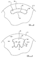
- Figure 3 is a plan view of an alternate form of intermediate layer 3.
- the intermediate layer is provided with apertures 12 which are associated with seams 13 and which are rather larger than the apertures provided in the embodiment of Figures 1 and 2, with the consequence that the spaces 17 between the adjacent apertures and seams are somewhat smaller than in the embodiment of Figures 1 and 2.
- Figure 4 illustrates the intermediate layer of yet another embodiment of the invention in which a plurality of apertures are formed in the intermediate layer.
- the apertures in the intermediate layer form two groups of apertures.
- the first group of four apertures 21 comprises four apertures, each of an elongate arcuate or "kidney" shape, the apertures being substantially aligned with a notional circle centred on the centre of the intermediate layer 3.
- the apertures 21 are located at a distance part way between the centre and the outer periphery of the intermediate layer 3.
- Each aperture is associated with a seam 22, again of elongate substantially arcuate form, the seam substantially surrounding the radially inner part of each aperture 21 and the ends of each aperture 21.
- Each seam defines a gap located radially outwardly of the associated apertures.
- a second group of four apertures 23 is provided at a position located immediately outwardly from the apertures 21.
- Each aperture 23 is of elongate arcuate or "kidney" shape, the apertures 23 lying on the periphery of a notional circle centred on the centre of the sheet 3.
- the apertures 23 are located adjacent the outer periphery of the sheet 3.
- Each aperture 23 is associated with a seam 24, of elongate arcuate form, the seam 24 lying adjacent the radially inner portion of each aperture 23.
- Each seam 24 defines a gap located radially outwardly of the associated aperture.
- the combination of the two series of apertures and the two series of seams provides a bag which inflates initially in a radially outwardly direction relatively rapidly, with gas flowing initially from the gas generator into a centrally located space 25, which is bounded by the first group of apertures 21, the gas then flowing through spaces 26 between the seams 22, to fill an annular space 27 located between the two series of apertures 21 and 23. The gas then flows through spaces 28 between the adjacent seams 24 to fill an annular outer peripheral space 29.
- This inflation of the bag causes initially a dome-shaped configuration to arise in the central region 25, which will serve to open the doors of a housing in which the air-bag is located, and subsequently radially a outwardly directed deployment of the bag as the spaces 27 and 29 become inflated.
- the bag will thus occupy a substantially planar condition. Gas will flow in increasing quantities through the apertures 21 and 23 to the space between the intermediate layer 3 and the upper layer 4, thus completing the inflation of the bag.
- Figure 5 illustrates part of an intermediate sheet 3 illustrating a particular form of aperture 30.
- the aperture is of arcuate form having slightly enlarged ends 31.
- the aperture presents a recessed edge 32 which is directed radially inwardly.
- the aperture is associated with a seam 33 which also presents a co-aligned recessed radially inwardly directed portion 34. This form of seam presents no abrupt edges where tearing might commence during rapid gas flow.
- FIG. 6 illustrates another embodiment of the invention in which each aperture 35 has a radially inwardly directed edge 36 which is of re-entrant form.
- the aperture has two diverging sides 37,38 connecting the radially inner side 36 to the radially outer side 39.
- a seam 40 associated with the aperture 35 also has a re-entrant radially inner portion 41 and two diverging side portions 42,43.
- the diverging side portions of the seams provided for adjacent apertures define converging flow paths 44 which are relatively constricted. The flow paths lead to an outer annular region 45.
- Figure 7 illustrates an intermediate layer for a passenger bag which is adapted to be initially stored within the dashboard of a motor vehicle.
- a passenger bag is of a rectangular form rather than a circular form.
- the intermediate layer 46 of the bag is of generally rectangular form and is provided with a plurality of apertures 47 which are located at positions spaced slightly inwardly from the outer periphery of the bag.
- the apertures 47 effectively lie on a notional oval.
- Each aperture 47 is provided with a seam 48 located adjacent the aperture and partially surrounding the aperture.
- Each seam 48 does not completely surround the aperture, and therefore defines a gap 49 between the opposed seam ends.
- the gap is located adjacent the respective aperture at a point which is located adjacent the outer periphery of the intermediate layer 46.
- Each seam extends in an unbroken form adjacent the radially inner side of each aperture and around the opposed ends of each aperture, and extends partly along the radially outer-most side of each aperture.
- seams may be effected by stitching, although any appropriate technique for bonding or securing together the adjacent layers of the bag may be utilised. It is to be clearly understood that it has been proposed previously to weave together the threads forming adjacent layers of fabric, so that in the regions where the threads are woven together, a seam is created. This technique is known as "one-piece weaving”. This technique may be used to fabric air-bags as described above.
- the shape and dimension of the apertures in combination with the positioning of the seams, will define the position and dimension of the flow paths to be followed by gas when the air-bag is inflated. Consequently, these features of the bag will determine the deployment pattern of the bag as it is inflated.
Landscapes
- Engineering & Computer Science (AREA)
- Mechanical Engineering (AREA)
- Air Bags (AREA)
Abstract
Description
- THE PRESENT INVENTION relates to an air-bag arrangement, and more particularly relates to an air-bag arrangement for use in a motor vehicle.
- It has been proposed previously to provide an air-bag within a motor vehicle, adapted to be inflated in the event that an accident should occur. Typically such an air-bag is formed of fabric and is associated with a gas generator that is adapted, when activated, to generate a substantial quantity of gas within a very short period of time. The air-bag is usually initially in a folded state, and the gas from the gas generator is directed to the interior of the air-bag. The air-bag thus unfolds and is inflated. When the air-bag is inflated, it is positioned in front of or adjacent an occupant of a motor vehicle in order to protect or cushion the occupant of the vehicle.
- When an air-bag of this type is inflated, it is not unusual for the part of the air-bag which is located closest to the occupant of the vehicle to be given a very substantial acceleration in a direction towards the occupant of the vehicle. Thus this part of the air-bag may impact with the occupant of the vehicle, especially if the occupant of the vehicle is sitting forwardly of the anticipated position. It is also no unusual for an air-bag of this type to become trapped if the air-bag is inflated when the occupant, to be protected by the air-bag, is sitting forwardly and is thus located very near to the unfolded bag. The presence of the occupant prevents the bag from unfolding in the correct manner, and as a consequence of the entrapment of the bag in this way, very high pressures can be generated within the bag. This can result in very high forces being applied to the occupant of the vehicle.
- Various attempts have been made to provide air-bags in which this problem is reduced. DE-A-4,412,326 shows an air-bag according to the preamble of
claim 1, having three super-imposed layers which define two chambers. Gas from the gas generator is initially supplied to the lower chamber which thus inflates first. Subsequently gas flows from this chamber into the second chamber through apertures formed in the intermediate layer. The movement of the intermediate layer is restricted by straps which are provided with tear seams. The arrangement is therefore relatively complex. - The present invention seeks to provide an improved air-bag arrangement.
- According to this invention there is provided an air-bag arrangement for use in a motor vehicle, the air-bag arrangement comprising a gas generator, means to activate the gas generator in response to an accident occurring, and an air-bag to receive gas from the gas generator, the air-bag comprising three super-imposed fabric layers, the outer peripheries of the three super-imposed layers being conjoined, there being a substantially centrally located aperture provided in the lower-most layer to receive the gas outlet of the gas generator, there being a plurality of apertures formed in the intermediate layer, there being means inter-connecting regions of the intermediate layer adjacent each of said apertures to the lower-most layer, said inter-connecting means partially surrounding each said aperture, but not being present in a region adjacent each aperture which is radially outwardly positioned relative to the centre of said intermediate layer.
- Preferably the means inter-connecting the intermediate layer and the lower layer comprise a seam.
- Conveniently the seam is a one-piece woven seam.
- Advantageously means inter-connecting the intermediate layer and the base layer extend in an unbroken form adjacent the radially inner side of each said aperture and around the opposed ends of said aperture and extend partly along the radially outer-most side of each aperture.
- Preferably said apertures lie on a notional circle.
- Conveniently each said aperture is of oval form.
- Alternatively each said aperture is of elongate arcuate form.
- Preferably two groups of said apertures are provided, one group of apertures lying on the periphery of a notional circle, centred on the centre of the intermediate layer of relatively small diameter and the other group of apertures comprising a group of apertures located on the periphery of a notional circle centred on the centre of the intermediate layer of a great diameter.
- Conveniently each aperture defines a re-entrant radially inner edge and each means inter-connecting the intermediate layer and the lower layer associated with said aperture defines a re-entrant radially inwardly directed edge.
- Advantageously the means inter-connecting the intermediate layer dan the lower layer adjacent each aperture define side portions which diverge outwardly from the radially inner side of the aperture to the radially outer side of each aperture.
- Advantageously the air-bag is adapted so that, on actuation of the gas generator, initially gas is supplied to a region located substantially centrally of the air-bag between the intermediate layer and the lower-most layer in order to inflate that region, and subsequently is passed to a radially outer substantially annular region located between the intermediate layer and the lower-most layer to inflate that region and, during the final stages of inflation of the bag, gas passes through the apertures in the intermediate layer to inflate the space between the intermediate layer and the upper layer.
- In order that the invention may be more readily understood, and so that further features thereof may be appreciated, the invention will now be described, by way of example, with reference to the accompanying drawings in which:
- FIGURE 1 is a diagrammatic exploded view of an air-bag in accordance with the invention,
- FIGURE 2 is a plan view of the air-bag of Figure 1, with the upper layer removed and with part of the intermediate layer cut away for the sake of clarity of illustration,
- FIGURE 3 is a view illustrating an alternate form of intermediate layer for use in embodiments of the invention,
- FIGURE 4 is a view corresponding to Figure 3 illustrating a further alternative form of intermediate layer for use in another embodiment of the invention,
- FIGURE 5 illustrates part of a further intermediate layer comprising part of another embodiment of the invention,
- FIGURE 6 illustrates part of yet a further intermediate layer that forms part of yet another embodiment of the invention, and
- FIGURE 7 illustrates part of yet a further intermediate layer that forms part of yet another embodiment of the invention.
-
- Referring initially to Figure 1 of the accompanying drawings, an air-bag arrangement in accordance with the invention comprise an air-
bag 1 which is formed of three super-imposed layers offabric seam 5. - The
lower-most layer 2 is provided with acentral aperture 6 surrounded by a plurality of relativelysmall apertures 7. Thecentral aperture 6 is adapted to receive a cylindrical housing 8 forming the gas outlet of the gas generator 9. The gas generator incorporates an outwardly directedflange 10 having a plurality of securingapertures 11 formed therein, thesecuring apertures 11 being adapted to be co-aligned with the relativelysmall apertures 7 to receive appropriate securing means such as bolts. - The intermediate layer of
fabric 3 is provided with a plurality of relatively evenly spacedapertures 12 therein, theapertures 12 being located substantially midway between the centre of theintermediate layer 3 and the outer periphery thereof. A seam, such as theseam 13, is provided in the region of eachaperture 12, inter-connecting theintermediate layer 3 to thelower-most layer 2. Eachseam 13 substantially surrounds the aperture which it lies adjacent, but the seam does not totally surround the aperture and therefore defines agap 14 between the opposed seam ends, the gap being located adjacent therespective aperture 12 at a point which is located adjacent the outer periphery of theintermediate layer 3. Thus the gap is effectively directed radially outwardly. Each seam extends in an unbroken form adjacent the radially inner side of each aperture and around the opposed ends of each aperture and extend partly along the radially outer-most side of each aperture. - The entire air-bag, when fabricated, will be folded and stored within a housing which is provided with initially closed doors, as is conventional.
- On activation of the gas generator, gas is initially ejected from the cylindrical housing 8 into the space between the
lower-most layer 2 and theintermediate layer 3 in theregion 15 which is bounded by theapertures 12 and theassociated seams 13. Theregion 15 thus commences to inflate and forms a relatively small "dome". This will serve to open the doors of the housing in which the folded air-bag is located. - Subsequently gas will flow radially outwardly, following radially outwardly flow paths 16 which pass through the spaces or
gaps 17 located between theadjacent apertures 12 and the associatedseams 13. - The radially outwardly directed flows then enter an
annular region 18 which is located radially outwardly of theapertures 12 and the associatedseams 13, and radially inwardly of theouter seam 5. On entering theannular space 18, the radially outwardly directed gas flows bifurcate to form circumferentially directedflows outer region 18 of the space between thelower layer 2 and theintermediate layer 3, providing that region with inherent rigidity. - The above-described flow of gas partially inflates the air-bag but causes the entire bag structure to deploy radially outwardly. The upper layer 4 of the air-bag is not given any substantial acceleration towards the occupant of the vehicle.
- It is to be appreciated that, as a consequence of the initial stages during the inflation of the air-bag, as described above, the bag will not become "trapped" as a consequence of the occupant of the vehicle being located in a forward position.
- The bag structure is now in the form of a substantially flat disc with a slightly domed
central region 15 and a inflated annularouter region 18. - The circumferentially directed
gas streams gaps 14 defined by theseams 13 and through theapertures 12 into the space between theintermediate layer 3 and the upper layer 4. This space then inflates to provide the inflated air-bag with its conventional substantially spherical shape. - It is to be understood that on activation of the air-bag as described above, initially a relatively small dome-
shaped area 15 is inflated to open the doors of the housing, and subsequently the outerannular region 18 is inflated to deploy the air-bag laterally or sideways, and only in the final stages of inflation is the space immediately adjacent the upper layer 4 of the air-bag inflated to cause that upper layer to move towards the occupant of the vehicle. Since the gas is supplied to the region between the intermediate layer and the upper layer after the upper layer has assumed a substantially planar condition, no one part of the upper layer is provided with an excessive velocity directed towards the occupant of the vehicle. The entire area of the upper layer thus gradually assures a spherical shape as inflation of the bag is completed. The term "gradually" is used in a relative sense since the entire inflation procedure is complete within a few milliseconds. - Whilst the invention has been described with reference to one embodiment, in the form of a spherical bag as may be intended to be mounted within a steering wheel, it is to be appreciated that modified embodiments may readily be devised, such as a bag to be mounted in a dashboard to protect a passenger in a vehicle.
- Figure 3 is a plan view of an alternate form of
intermediate layer 3. In this particular embodiment of the invention, the intermediate layer is provided withapertures 12 which are associated withseams 13 and which are rather larger than the apertures provided in the embodiment of Figures 1 and 2, with the consequence that thespaces 17 between the adjacent apertures and seams are somewhat smaller than in the embodiment of Figures 1 and 2. - Figure 4 illustrates the intermediate layer of yet another embodiment of the invention in which a plurality of apertures are formed in the intermediate layer. The apertures in the intermediate layer form two groups of apertures. The first group of four
apertures 21 comprises four apertures, each of an elongate arcuate or "kidney" shape, the apertures being substantially aligned with a notional circle centred on the centre of theintermediate layer 3. Theapertures 21 are located at a distance part way between the centre and the outer periphery of theintermediate layer 3. Each aperture is associated with aseam 22, again of elongate substantially arcuate form, the seam substantially surrounding the radially inner part of eachaperture 21 and the ends of eachaperture 21. Each seam defines a gap located radially outwardly of the associated apertures. - A second group of four
apertures 23 is provided at a position located immediately outwardly from theapertures 21. Eachaperture 23 is of elongate arcuate or "kidney" shape, theapertures 23 lying on the periphery of a notional circle centred on the centre of thesheet 3. Theapertures 23 are located adjacent the outer periphery of thesheet 3. Eachaperture 23 is associated with aseam 24, of elongate arcuate form, theseam 24 lying adjacent the radially inner portion of eachaperture 23. Eachseam 24 defines a gap located radially outwardly of the associated aperture. - The combination of the two series of apertures and the two series of seams provides a bag which inflates initially in a radially outwardly direction relatively rapidly, with gas flowing initially from the gas generator into a centrally located
space 25, which is bounded by the first group ofapertures 21, the gas then flowing through spaces 26 between theseams 22, to fill anannular space 27 located between the two series ofapertures spaces 28 between theadjacent seams 24 to fill an annular outerperipheral space 29. - This inflation of the bag causes initially a dome-shaped configuration to arise in the
central region 25, which will serve to open the doors of a housing in which the air-bag is located, and subsequently radially a outwardly directed deployment of the bag as thespaces apertures intermediate layer 3 and the upper layer 4, thus completing the inflation of the bag. - Figure 5 illustrates part of an
intermediate sheet 3 illustrating a particular form ofaperture 30. The aperture is of arcuate form having slightly enlarged ends 31. The aperture presents a recessededge 32 which is directed radially inwardly. The aperture is associated with aseam 33 which also presents a co-aligned recessed radially inwardly directedportion 34. This form of seam presents no abrupt edges where tearing might commence during rapid gas flow. - Figure 6 illustrates another embodiment of the invention in which each
aperture 35 has a radially inwardly directededge 36 which is of re-entrant form. The aperture has two divergingsides 37,38 connecting the radiallyinner side 36 to the radiallyouter side 39. - A
seam 40 associated with theaperture 35 also has a re-entrant radiallyinner portion 41 and two divergingside portions 42,43. The diverging side portions of the seams provided for adjacent apertures define convergingflow paths 44 which are relatively constricted. The flow paths lead to an outerannular region 45. - The configuration of the seams shown in Figure 6 minimises any risk of the seam being damaged during inflation of the bag, and the configuration of the
flow paths 44 helps to ensure an ideal inflation characteristic. - Figure 7 illustrates an intermediate layer for a passenger bag which is adapted to be initially stored within the dashboard of a motor vehicle. Conventionally, such a passenger bag is of a rectangular form rather than a circular form. Thus, as can be seen in Figure 7, the
intermediate layer 46 of the bag is of generally rectangular form and is provided with a plurality ofapertures 47 which are located at positions spaced slightly inwardly from the outer periphery of the bag. Theapertures 47 effectively lie on a notional oval. Eachaperture 47 is provided with aseam 48 located adjacent the aperture and partially surrounding the aperture. Eachseam 48 does not completely surround the aperture, and therefore defines agap 49 between the opposed seam ends. The gap is located adjacent the respective aperture at a point which is located adjacent the outer periphery of theintermediate layer 46. Thus the gap is effectively directed radially outwardly. Each seam extends in an unbroken form adjacent the radially inner side of each aperture and around the opposed ends of each aperture, and extends partly along the radially outer-most side of each aperture. - Whilst, in the foregoing description, reference has been made to seams, it is to be appreciated that the seams may be effected by stitching, although any appropriate technique for bonding or securing together the adjacent layers of the bag may be utilised. It is to be clearly understood that it has been proposed previously to weave together the threads forming adjacent layers of fabric, so that in the regions where the threads are woven together, a seam is created. This technique is known as "one-piece weaving". This technique may be used to fabric air-bags as described above.
- The shape and dimension of the apertures, in combination with the positioning of the seams, will define the position and dimension of the flow paths to be followed by gas when the air-bag is inflated. Consequently, these features of the bag will determine the deployment pattern of the bag as it is inflated.
Claims (10)
- An air-bag arrangement for use in a motor vehicle, the air-bag arrangement comprising a gas generator, means to activate the gas generator(9) in response to an accident occurring, and an air-bag(1) to receive gas from the gas generator, the air-bag comprising three super-imposed fabric layers(2,3,4), the outer peripheries of the three super-imposed layers being conjoined(5), there being a substantially centrally located aperture(6) provided in the lower-most layer(2) to receive the gas outlet(8) of the gas generator, there being a plurality of apertures(12) formed in the intermediate layer(3), there being means(13) inter-connecting regions of the intermediate layer(3) adjacent each of said apertures(12) to the lower-most layer(2), characterised in that said inter-connecting means partially surround each said aperture, and are not present in a region(14) adjacent each aperture(12) which is radially outwardly positioned relative to the centre of said intermediate layer, the arrangement being adapted so that on actuation of the gas generator, initially gas is supplied to a region(15) located substantially centrally of the air-bag between the intermediate layer(3) and the lower-most layer(2) in order to inflate that region, and subsequently is passed to a radially outer substantially annular region(18) located between the intermediate layer(3) and the lower-most layer(2) to inflate that region and, during the final stages of inflation of the bag, gas passes through the apertures(12) in the intermediate layer to inflate the space between the intermediate layer(3) and the upper layer(4).
- An air-bag according to Claim 1 wherein the means(13) inter-connecting the intermediate layer and the lower layer comprise a seam(13).
- An air-bag according to Claim 2 wherein the seam(13) is a one-piece woven seam.
- An air-bag arrangement according to any one of the preceding Claims wherein means(13) inter-connecting the intermediate layer(3) and the base layer(2) extend in an unbroken form adjacent the radially inner side of each said aperture(12) and around the opposed ends of said aperture and extend partly along the radially outer-most side of each aperture.
- An air-bag arrangement according to any one of the preceding Claims wherein said apertures(12) lie on a notional circle.
- An air-bag arrangement according to any one of the preceding Claims wherein each said aperture( 12) is of oval form.
- An air-bag arrangement according to any one of Claims 1 to 5 wherein each said aperture(12) is of elongate arcuate form.
- An air-bag arrangement according to any one of the preceding Claims wherein two groups of said apertures(12) are provided, one group of apertures(21) lying on the periphery of a notional circle, centred on the centre of the intermediate layer(3) of relatively small diameter and the other group of apertures(23) comprising a group of apertures located on the periphery of a notional circle centred on the centre of the intermediate layer(3) of a great diameter.
- An air-bag arrangement according to any one of the preceding Claims wherein each aperture(12) defines a re-entrant radially inner edge(36) and each means(40) inter-connecting the intermediate layer and the lower layer associated with said aperture defines a re-entrant radially inwardly directed portion(41).
- An air-bag arrangement according to any one of the preceding Claims wherein the means(40) inter-connecting the intermediate layer(3) and the lower layer(2) adjacent each aperture define side portions(42,43) which diverge outwardly from the radially inner edge(36) of the aperture to the radially outer edge of each aperture.
Applications Claiming Priority (3)
| Application Number | Priority Date | Filing Date | Title |
|---|---|---|---|
| GB9706067 | 1997-03-24 | ||
| GB9706067A GB2323569B (en) | 1997-03-24 | 1997-03-24 | Improvements in or relating to an air-bag arrangement |
| PCT/SE1998/000488 WO1998042543A1 (en) | 1997-03-24 | 1998-03-18 | Improvement in or relating to an air-bag arrangement |
Publications (2)
| Publication Number | Publication Date |
|---|---|
| EP0969991A1 EP0969991A1 (en) | 2000-01-12 |
| EP0969991B1 true EP0969991B1 (en) | 2004-05-26 |
Family
ID=10809770
Family Applications (1)
| Application Number | Title | Priority Date | Filing Date |
|---|---|---|---|
| EP98911327A Expired - Lifetime EP0969991B1 (en) | 1997-03-24 | 1998-03-18 | Improvement in or relating to an air-bag arrangement |
Country Status (8)
| Country | Link |
|---|---|
| US (1) | US6267408B1 (en) |
| EP (1) | EP0969991B1 (en) |
| JP (1) | JP2001518036A (en) |
| CN (1) | CN1130294C (en) |
| BR (1) | BR9808407A (en) |
| DE (1) | DE69824158T2 (en) |
| GB (1) | GB2323569B (en) |
| WO (1) | WO1998042543A1 (en) |
Families Citing this family (17)
| Publication number | Priority date | Publication date | Assignee | Title |
|---|---|---|---|---|
| KR20000068628A (en) | 1997-11-28 | 2000-11-25 | 히로세 마꼬또 | Air-bag, Air-bag device and steering wheel |
| JP3239118B2 (en) * | 1999-09-30 | 2001-12-17 | 日本プラスト株式会社 | Airbag and airbag device |
| US6626459B2 (en) | 2000-03-31 | 2003-09-30 | Toyoda Gosei Co., Ltd. | Air bag for steering wheel |
| US6554316B2 (en) | 2001-03-08 | 2003-04-29 | Autoliv Asp, Inc. | Multi-chamber airbag gas venting system |
| GB2407071A (en) * | 2003-10-16 | 2005-04-20 | Autoliv Dev | A vehicle air-bag comprising a vent hole |
| US7210702B2 (en) | 2004-06-23 | 2007-05-01 | Autoliv Asp, Inc. | Airbag cushion with improved fabric deflector design |
| CN1259207C (en) * | 2004-11-30 | 2006-06-14 | 湖南大学 | Sandwich tube airbag |
| JP4807004B2 (en) * | 2004-12-22 | 2011-11-02 | タカタ株式会社 | Airbag device |
| JP4534762B2 (en) * | 2004-12-28 | 2010-09-01 | タカタ株式会社 | Airbag device for driver's seat |
| JP4811028B2 (en) | 2005-03-07 | 2011-11-09 | タカタ株式会社 | Air bag and air bag device |
| US7648166B2 (en) * | 2005-05-04 | 2010-01-19 | Tk Holdings Inc. | Occupant protection apparatus |
| US8764057B1 (en) | 2013-01-17 | 2014-07-01 | Autoliv Asp, Inc. | Multi-chamber driver airbags |
| US8840139B1 (en) | 2013-03-14 | 2014-09-23 | Autoliv Asp, Inc. | Airbag with deflector |
| US9126562B2 (en) * | 2013-11-18 | 2015-09-08 | Hyundai Mobis Co., Ltd. | Airbag |
| JP2017081517A (en) * | 2015-10-30 | 2017-05-18 | トヨタ自動車株式会社 | Airbag device for driver's seat |
| US10711141B1 (en) * | 2016-10-04 | 2020-07-14 | Triton Systems, Inc. | Nickel free conductive filler |
| US11198411B2 (en) * | 2019-04-18 | 2021-12-14 | Autoliv Asp. Inc. | Energy-absorbing airbag diffusers and related airbag assemblies |
Family Cites Families (11)
| Publication number | Priority date | Publication date | Assignee | Title |
|---|---|---|---|---|
| US5240283A (en) | 1990-04-27 | 1993-08-31 | Daicel Chemical Industries, Ltd. | Air bag type occupant protector |
| JP3039068B2 (en) * | 1991-12-04 | 2000-05-08 | タカタ株式会社 | Air bag |
| DE4142326B4 (en) | 1991-12-20 | 2004-07-22 | Bayerische Motoren Werke Ag | Airbag for a motor vehicle |
| US5358273A (en) * | 1992-03-09 | 1994-10-25 | Toyo Tire & Rubber Co., Ltd. | Inflatable bags for airbag passive restraint systems for driver and method for production thereof |
| GB2268128B (en) * | 1992-06-26 | 1995-10-04 | Rover Group | An air bag for a motor vehicle |
| JP3352203B2 (en) * | 1993-12-08 | 2002-12-03 | タカタ株式会社 | Airbag device |
| US5839755A (en) * | 1994-03-03 | 1998-11-24 | Trw Vehicle Safety Systems Inc. | Method and apparatus for restraining a vehicle occupant |
| US5560649A (en) * | 1995-04-25 | 1996-10-01 | Morton International, Inc. | Air bag cushion having variable volume |
| US5501488A (en) * | 1995-04-28 | 1996-03-26 | Morton International, Inc. | Airbag with alternate deployment modes |
| US5586782A (en) * | 1995-06-26 | 1996-12-24 | Alliedsignal Inc. | Dual pressure side impact air bag |
| US5669628A (en) * | 1996-04-08 | 1997-09-23 | Morton International, Inc. | Air bag cushion protection during both normal and out of position deployments |
-
1997
- 1997-03-24 GB GB9706067A patent/GB2323569B/en not_active Expired - Fee Related
-
1998
- 1998-03-18 BR BR9808407-0A patent/BR9808407A/en not_active IP Right Cessation
- 1998-03-18 US US09/381,827 patent/US6267408B1/en not_active Expired - Fee Related
- 1998-03-18 WO PCT/SE1998/000488 patent/WO1998042543A1/en not_active Ceased
- 1998-03-18 EP EP98911327A patent/EP0969991B1/en not_active Expired - Lifetime
- 1998-03-18 DE DE69824158T patent/DE69824158T2/en not_active Expired - Fee Related
- 1998-03-18 JP JP54555598A patent/JP2001518036A/en not_active Ceased
- 1998-03-18 CN CN98805068A patent/CN1130294C/en not_active Expired - Fee Related
Also Published As
| Publication number | Publication date |
|---|---|
| CN1255899A (en) | 2000-06-07 |
| CN1130294C (en) | 2003-12-10 |
| GB2323569B (en) | 2001-05-09 |
| DE69824158D1 (en) | 2004-07-01 |
| JP2001518036A (en) | 2001-10-09 |
| US6267408B1 (en) | 2001-07-31 |
| GB9706067D0 (en) | 1997-05-14 |
| WO1998042543A1 (en) | 1998-10-01 |
| EP0969991A1 (en) | 2000-01-12 |
| DE69824158T2 (en) | 2005-06-23 |
| BR9808407A (en) | 2000-05-16 |
| GB2323569A (en) | 1998-09-30 |
Similar Documents
| Publication | Publication Date | Title |
|---|---|---|
| US6267408B1 (en) | Air-bag arrangement | |
| US6361067B1 (en) | Airbag with interior deflection device | |
| US5226671A (en) | Air bag structure and method of forming | |
| EP1452407B1 (en) | Air bag device for knee protection | |
| US5529337A (en) | Air bag device | |
| EP1442944B1 (en) | Airbag and airbag apparatus | |
| EP0739784B1 (en) | Airbag with variable deployment modes | |
| US7618060B2 (en) | Air bag module with an integral shield | |
| US6834884B2 (en) | Airbag | |
| US5957493A (en) | Airbag check valve | |
| US5833265A (en) | Airbag with excursion restrictors | |
| EP1344693B1 (en) | Driver side airbag with particle diverter | |
| US7891705B2 (en) | Tension cushion air bag module | |
| JP2003034208A (en) | Airbag | |
| US6422600B1 (en) | Airbag module | |
| JPH1067292A (en) | Knee holding device for vehicle occupant | |
| EP1636072B1 (en) | An air-bag | |
| EP1107884B1 (en) | Airbag with chambers | |
| US10723307B2 (en) | Airbag module | |
| JP2002362274A (en) | Air bag and air bag device | |
| US6464249B1 (en) | Selectively buffered dual stage air bag assembly, and method of using same | |
| JP2002029354A (en) | Air bag | |
| US7198286B2 (en) | Airbag device | |
| KR101177810B1 (en) | Low risk deployment driver airbag system | |
| US20070222194A1 (en) | Air bag module with a shield |
Legal Events
| Date | Code | Title | Description |
|---|---|---|---|
| PUAI | Public reference made under article 153(3) epc to a published international application that has entered the european phase |
Free format text: ORIGINAL CODE: 0009012 |
|
| AK | Designated contracting states |
Kind code of ref document: A1 Designated state(s): DE ES FR GB |
|
| 17P | Request for examination filed |
Effective date: 19990913 |
|
| GRAP | Despatch of communication of intention to grant a patent |
Free format text: ORIGINAL CODE: EPIDOSNIGR1 |
|
| GRAS | Grant fee paid |
Free format text: ORIGINAL CODE: EPIDOSNIGR3 |
|
| GRAA | (expected) grant |
Free format text: ORIGINAL CODE: 0009210 |
|
| AK | Designated contracting states |
Kind code of ref document: B1 Designated state(s): DE ES FR GB |
|
| PG25 | Lapsed in a contracting state [announced via postgrant information from national office to epo] |
Ref country code: FR Free format text: LAPSE BECAUSE OF NON-PAYMENT OF DUE FEES Effective date: 20040526 |
|
| REG | Reference to a national code |
Ref country code: GB Ref legal event code: FG4D |
|
| REF | Corresponds to: |
Ref document number: 69824158 Country of ref document: DE Date of ref document: 20040701 Kind code of ref document: P |
|
| PG25 | Lapsed in a contracting state [announced via postgrant information from national office to epo] |
Ref country code: ES Free format text: LAPSE BECAUSE OF FAILURE TO SUBMIT A TRANSLATION OF THE DESCRIPTION OR TO PAY THE FEE WITHIN THE PRESCRIBED TIME-LIMIT Effective date: 20040906 |
|
| PG25 | Lapsed in a contracting state [announced via postgrant information from national office to epo] |
Ref country code: GB Free format text: LAPSE BECAUSE OF NON-PAYMENT OF DUE FEES Effective date: 20050318 |
|
| PLBE | No opposition filed within time limit |
Free format text: ORIGINAL CODE: 0009261 |
|
| STAA | Information on the status of an ep patent application or granted ep patent |
Free format text: STATUS: NO OPPOSITION FILED WITHIN TIME LIMIT |
|
| 26N | No opposition filed |
Effective date: 20050301 |
|
| EN | Fr: translation not filed | ||
| GBPC | Gb: european patent ceased through non-payment of renewal fee |
Effective date: 20050318 |
|
| PGFP | Annual fee paid to national office [announced via postgrant information from national office to epo] |
Ref country code: DE Payment date: 20060316 Year of fee payment: 9 |
|
| PG25 | Lapsed in a contracting state [announced via postgrant information from national office to epo] |
Ref country code: DE Free format text: LAPSE BECAUSE OF NON-PAYMENT OF DUE FEES Effective date: 20071002 |