EP0969582A2 - Elastic isolating element for wedging a coil, in particular an electric machine stator coil - Google Patents
Elastic isolating element for wedging a coil, in particular an electric machine stator coil Download PDFInfo
- Publication number
- EP0969582A2 EP0969582A2 EP99810556A EP99810556A EP0969582A2 EP 0969582 A2 EP0969582 A2 EP 0969582A2 EP 99810556 A EP99810556 A EP 99810556A EP 99810556 A EP99810556 A EP 99810556A EP 0969582 A2 EP0969582 A2 EP 0969582A2
- Authority
- EP
- European Patent Office
- Prior art keywords
- metal spring
- insulating element
- spring core
- element according
- core
- Prior art date
- Legal status (The legal status is an assumption and is not a legal conclusion. Google has not performed a legal analysis and makes no representation as to the accuracy of the status listed.)
- Granted
Links
Images


Classifications
-
- H—ELECTRICITY
- H02—GENERATION; CONVERSION OR DISTRIBUTION OF ELECTRIC POWER
- H02K—DYNAMO-ELECTRIC MACHINES
- H02K3/00—Details of windings
- H02K3/46—Fastening of windings on the stator or rotor structure
- H02K3/48—Fastening of windings on the stator or rotor structure in slots
- H02K3/487—Slot-closing devices
Definitions
- the present invention relates to the field of rotating art electrical machines. It relates to an elastic insulating element for wedging a winding, in particular the stator winding, of an electrical machine in the provided grooves of a sheet metal body.
- Such an insulating element is e.g. from US-A-3,949,255 or US-A-4,200,816.
- Elastic insulating material elements are found particularly in the stators of rotating ones electrical machines for elastic fastening (wedging) of the stator winding use in the grooves of the sheet metal body.
- the stator windings are usually insulated conductor bundles with a rectangular cross-section, those with a small Play in the grooves of the stator body. To ensure that the To ensure winding in the slot, the wedging must be stressed due to the weight of the winding and electromagnetic forces during operation and withstand short circuit in such a way that no loosening and vibration the winding becomes possible.
- Conventional slot lock wedges especially for smaller machine units consist of a prism-shaped or machined insulating material.
- Insulating material is usually used with glass fiber reinforced epoxy resin (see e.g. U.S.-A-4,200,818).
- a plastic-elastic intermediate layer (Fleece, felt) these wedges are axially in the grooves of the laminated core tooth heads and partly in an impregnation process with the winding and the sheet metal body glued.
- Another conventional wedge design is based on the mode of operation of double wedges. Two superimposed flat wedges are in the keyways inserted, the biasing force by axially driving the a flat wedge is built (see e.g. US-A-3,949,255).
- Plastic wave springs US-A-3,949,255.
- elastic wave springs are between a rigid wedge and the winding (or between two rigid wedges).
- the necessary pretensioning force is achieved by defined compression the corrugated spring reached.
- a shrinkage of the filling with filling processes is caused by the spring spring is compensated.
- Another solution to elastic Wedging represents the use of elastic wedges Wedges or recessed wedges in the middle (convex-concave wedges) become flexibility the wedges increases and the preload forces are reduced. Even with this solution can be compensated to a certain extent.
- the insulating element has a strip-shaped metal spring core has, which is surrounded on all sides by a covering made of an insulating material.
- the essence of the invention is no longer the elastic element Insulated body to use, but the embedded metal spring core.
- the insulating material is only functional for the electrical insulation of the metal spring core and possibly in addition to the shape of the corresponding one Component necessary. Its contribution to the mechanical behavior of the component must on the other hand, be at most marginal.
- the metal spring core which is preferred made of a non-magnetic, resilient metal, in particular a stainless steel, and a thickness of a few millimeters, preferably between 2 and 3 mm, exhibits practically no flow behavior even at higher temperatures.
- a first preferred embodiment of the insulating element according to the invention is characterized in that the metal spring core has means by which limit eddy currents induced in the metal spring core. Hereby is prevented by the high air gap induction in the machine strong Eddy currents with the corresponding thermal effects in the elements be stimulated.
- the means for limiting induced eddy currents comprise slot-shaped incisions which are made in the longitudinal direction of the Metal spring core arranged in each case distributed from the longitudinal edges of the metal spring core protrude into the interior of the metal spring core. By the Providing the cuts, the metal spring core is divided into individual sectors. This ensures that possible loops in which eddy currents can flow limited to electrically and thermally uncritical geometrical dimensions become.
- the slit is to be arranged so that the mechanical spring action of the metal spring core remains optimal. This can be achieved, for example that the incisions alternate from the opposite Protrude longitudinal edges of the metal spring core into the interior of the metal spring core, and that the incisions starting from the different longitudinal edges overlap inside the metal spring core.
- the covering of the insulating material element according to the invention preferably consists made of a fiber-reinforced plastic, in particular a high-temperature thermoset or high temperature thermoplastic. This ensures that Put the wrapping or embedding material under pressure is negligibly small.
- additional means for improving the mechanical connection between the metal spring core and the casing is provided.
- the metal spring core with a Adhesion promoter is pretreated.
- the embedding material ensures an even application of force.
- the insulating material element according to the invention can optionally be used both as a slot wedge as well as a corrugated spring, and alone as a slot wedge or as a corrugated spring or in a combination of a slot wedge and a corrugated spring be used.
- the element is designed as a slot wedge, it can preferably be on the A concave cross-sectional profile on the bottom or a convex cross-section on the top exhibit. As a result, the elastic mechanical properties can be positive to be influenced.
- the metal spring core is corrugated.
- the waves preferably close with the longitudinal direction of the wave spring an angle of less than 90 °, in particular about 45 °.
- the metal spring core formed from a strip with straight longitudinal edges, and are for limitation the eddy currents provided in the metal spring core incisions run the incisions are substantially perpendicular to the shafts, which means simultaneously optimal elastic and electrical properties of the corrugated spring can be achieved.
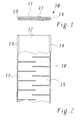
- FIG. 1 and 2 show in cross section and in a partially sectioned top view a first preferred embodiment of an insulating element according to the Invention in the form of a slot wedge 10.
- the slot wedge 10 is formed as a flat, elongated strip and laterally by two V-shaped ones Longitudinal sides 13, 14 delimited, so that there is an overall prismatic Cross-sectional profile (Fig. 1) results, as is customary and characteristic for slot wedges is.
- the slot lock wedge 10 comprises a metal spring core 11 in the form a sheet metal strip, which is surrounded on all sides by a covering 12 made of insulating material is that a direct contact of the core with the laminated sheet metal body of the Stators and thus stray metal flows with local hot spots and Danger of massive sheet metal closings prevented.
- the metal spring core 11 preferably has a simple rectangular cross-section and has a thickness of several Millimeters, especially in the range of 2 to 3 mm. It preferably exists made of a temperature-resistant non-magnetic metal with spring properties, for example a stainless steel.
- the envelope 12 has not only one insulating function, but at the same time serves to lock slot 10 by appropriate shaping in a simple manner the necessary prismatic To give cross-sectional profile.
- the metal spring core 11 is in the sheath 12 from a glass fiber reinforced Plastic embedded. All thermosets are also suitable as binders Thermoplastics, which can be sensibly selected depending on the intended temperature range are. It should be noted that the plastic is only functional in this application still for insulation of the metal spring core and possibly in addition to (e.g. prismatic) Shape of the slot wedge 10 is necessary. His contribution to mechanical behavior of the component, however, is at most marginal. However, it is ensure that the embedding material is placed under pressure should be negligibly small, which is why unreinforced plastics seem less suitable for this purpose. When choosing the fiber reinforced Plastic for the casing 12 and the pretreatment of the metal spring core 11 (e.g. through the use of an adhesion promoter) ensures good interface adhesion (Gluing) to ensure delamination caused by shear stresses to avoid.
- Gluing interface adhesion
- the Metal spring core 11 is not solid, but according to Fig. 2 by alternately arranged, from the longitudinal edges 13, 14 inside running and overlapping incisions 15 in individual sectors be divided, which are connected in a meandering shape. This ensures that possible loops in which eddy currents can flow on electrical and thermally uncritical geometric dimensions can be limited.
- the one with the incisions 15 connected slit is to be arranged so that the mechanical Spring action of the metal spring core 11 is optimally preserved.
- FIG. 4 Another embodiment of the slit with otherwise the same interior Structure is shown in Fig. 4.
- the incisions 15 of the starting from two longitudinal edges 13, 14 in pairs opposite and thus form one herringbone incised pattern.
- the intermediate sectors still holes 16 arranged distributed.
- holes 16 can of course also be of other types regular or irregularly shaped recesses are provided.
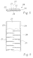
- a slot wedge shown in FIGS. 5 and 6 20 is the shape and slot for the metal spring core 21 (Incisions 25) of the metal spring core 11 from FIG. 2 taken over, however, that Cross-sectional profile of the sheath 22 according to FIG. 5 changed in such a way that the cover 22 is thicker overall, but on the underside 26 is concave or convex on the top 27.
- Convex-concave formation of the wedge is the total for a given thickness Flexibility increased and the preload reduced.
- the embodiments of the insulating element shown in FIGS. 7 to 9 according to the invention relate to the design as a corrugated spring 30 or 40, which together with appropriate slot lock wedges for elastic wedging the winding can be used.
- the wave spring 30 from FIGS. 7 and 8 comprises a corrugated metal spring core 31, which in turn of a sheath 32 made of fiber-reinforced insulating material (high-temperature epoxy) is surrounded.
- the corrugated metal spring core 31 is each with a glass thermoset prepreg assembled into a sandwich on the top and bottom and then cured in an appropriate waveform.
- the resulting one Corrugated spring 30 has the corrugation with corrugations which can be seen in the side view of FIG.
- the slit with the alternating and overlapping incisions 34 is also oriented at an oblique angle to the longitudinal axis, such that the incisions 34 are perpendicular to the direction of the shafts 33.
- the waves of the wave spring 40 are designed and oriented in the same way as the shafts 33 of the Corrugated spring 30 from Fig. 7, 8.
Abstract
Description
Die vorliegende Erfindung bezieht sich auf das Gebiet der Technik rotierender elektrischer Maschinen. Sie betrifft ein elastisches Isolierstoffelement für die Verkeilung einer Wicklung, insbesondere der Statorwicklung, einer elektrischen Maschine in den dafür vorgesehenen Nuten eines Blechkörpers.The present invention relates to the field of rotating art electrical machines. It relates to an elastic insulating element for wedging a winding, in particular the stator winding, of an electrical machine in the provided grooves of a sheet metal body.
Ein solches Isolierstoffelement ist z.B. aus der Druckschrift US-A-3,949,255 oder US-A-4,200,816 bekannt. Such an insulating element is e.g. from US-A-3,949,255 or US-A-4,200,816.
Elastische Isolierstoffelemente finden insbesondere in den Statoren von rotierenden elektrischen Maschinen zur elastischen Befestigung (Verkeilung) der Statorwicklung in den Nuten des Blechkörpers Verwendung. Die Statorwicklungen sind in der Regel isolierte Leiterbündel mit rechteckigem Querschnitt, die mit geringem Spiel in die Nuten des Statorkörpers eingelegt sind. Um einen festen Sitz der Wicklung in der Nut zu gewährleisten, muss die Verkeilung Beanspruchungen durch die Eigenmasse der Wicklung und durch elektromagnetische Kräfte im Betrieb und Kurzschlussfall in der Weise standhalten, dass keine Lockerung und Vibration der Wicklung möglich wird.Elastic insulating material elements are found particularly in the stators of rotating ones electrical machines for elastic fastening (wedging) of the stator winding use in the grooves of the sheet metal body. The stator windings are usually insulated conductor bundles with a rectangular cross-section, those with a small Play in the grooves of the stator body. To ensure that the To ensure winding in the slot, the wedging must be stressed due to the weight of the winding and electromagnetic forces during operation and withstand short circuit in such a way that no loosening and vibration the winding becomes possible.
Konventionelle Nutverschlusskeile, insbesondere für kleinere Maschineneinheiten bestehen aus einem prismenförmig gearbeiteten bzw. bearbeiteten Isolierstoff. Als Isolierstoff wird in der Regel glasfaserverstärktes Epoxidharz verwendet (siehe z.B. die US-A-4,200,818). Unter Zuhilfenahme einer plastisch-elastischen Zwischenlage (Vlies, Filz) werden diese Keile axial in die Nuten der Blechpaket-Zahnköpfe und zum Teil in einem Imprägnierprozess mit der Wicklung und dem Blechkörper verklebt. Eine andere, konventionelle Keilkonstruktion beruht auf der Wirkungsweise von Doppelkeilen. Zwei übereinanderliegende Flachkeile werden in die Keilnuten eingeschoben, wobei die Vorspannkraft durch axiales Treiben des einen Flachkeils aufgebaut wird (siehe z.B. die US-A-3,949,255).Conventional slot lock wedges, especially for smaller machine units consist of a prism-shaped or machined insulating material. As Insulating material is usually used with glass fiber reinforced epoxy resin (see e.g. U.S.-A-4,200,818). With the help of a plastic-elastic intermediate layer (Fleece, felt) these wedges are axially in the grooves of the laminated core tooth heads and partly in an impregnation process with the winding and the sheet metal body glued. Another conventional wedge design is based on the mode of operation of double wedges. Two superimposed flat wedges are in the keyways inserted, the biasing force by axially driving the a flat wedge is built (see e.g. US-A-3,949,255).
Nachteil beider Keilformen ist, dass die Keilkonstruktion in sich steif und unflexibel ist. Die Vorspannkraft ist undefiniert. Thermische Ausdehnungen der Nutfüllung führen wegen der steifen Verkeilung zu einer enormen Erhöhung der Druckkräfte auf die Nuffüllung, was zu einem sehr starken Setzen der Nutfüllung mit resultierender unerwünschter Lockerung der Wicklung führen kann.The disadvantage of both wedge shapes is that the wedge construction is inherently rigid and inflexible is. The preload is undefined. Thermal expansion of the slot filling lead to an enormous increase in pressure due to the stiff wedging on the nuf filling, resulting in a very strong setting of the groove filling with the resulting unwanted loosening of the winding can result.
Den Nachteil der unelastischen Verkeilung eliminiert eine Verkeilung mit Hilfe von Kunststoff-Wellfedern (US-A-3,949,255). Dazu werden elastische Wellfedern zwischen einen steifen Keil und die Wicklung (oder zwischen zwei steife Keile) eingelegt. Die notwendige Vorspannkraft wird durch definiertes Zusammendrücken der Wellfeder erreicht. Ein Schwund der Nuffüllung durch Setzvorgänge wird durch das Nachfedern der Wellfeder kompensiert. Eine andere Lösung zur elastischen Verkeilung stellt die Verwendung elastischer Keile dar. Durch entsprechend dünne keile bzw. mittig ausgenommene Keile (Konvex-Konkav-Keile) wird die Flexibilität der Keile erhöht und die Vorspannkräfte werden reduziert. Auch mit dieser Lösung können Setzvorgänge bei der Nuffüllung in gewissem Rahmen ausgeglichen werden.The disadvantage of inelastic wedging is eliminated by using Plastic wave springs (US-A-3,949,255). For this, elastic wave springs are between a rigid wedge and the winding (or between two rigid wedges). The necessary pretensioning force is achieved by defined compression the corrugated spring reached. A shrinkage of the filling with filling processes is caused by the spring spring is compensated. Another solution to elastic Wedging represents the use of elastic wedges Wedges or recessed wedges in the middle (convex-concave wedges) become flexibility the wedges increases and the preload forces are reduced. Even with this solution can be compensated to a certain extent.
Eine dauerhafte Aufrechterhaltung der Mindestvorspannkraft ist bei beiden elastischen Verkeilmethoden nur gesichert, wenn die elastischen Kunststoffelemente ihre elastischen Eigenschaften auch vollständig beibehalten. bekannt ist jedoch, dass alle verstärkten Kunststoffe unter Dauerbiege-Beanspruchung und insbesondere erhöhten Temperaturen zum Fliessen bzw. Kriechen neigen. Wie aufwendige Untersuchungen gezeigt haben, sind nennenswerte Fliessvorgänge bereits bei üblichen Betriebstemperaturen zu erwarten, selbst wenn faserverstärkte Kunststoffe mit warmfesten Bindemitteln eingesetzt werden. Im Falle von Betriebsstörungen mit kurzzeitig weiter erhöhten Temperaturen können derartige Fliessvorgänge kritisch werden, so dass mit einer Lockerung der Wicklung zu rechnen ist.A permanent maintenance of the minimum prestressing force is elastic with both Wedge methods only secured when the elastic plastic elements maintain their elastic properties completely. is known, however that all reinforced plastics under permanent bending stress and in particular increased temperatures tend to flow or creep. How elaborate Studies have shown that significant flow processes are already at usual operating temperatures, even if fiber-reinforced plastics can be used with heat-resistant binders. In the event of malfunctions With briefly further increased temperatures, such flow processes can occur become critical, so that loosening of the winding can be expected.
Es ist daher Aufgabe der Erfindung, ein Isolierstoffelement für die Verkeilung von Wicklungen zu schaffen, bei welchem ein Fliessen/Kriechen des Isolierstoffes bzw. die Auswirkungen eines Fliessens/Kriechens des Isolierstoffes auf das elastische Verhalten der Verkeilung sicher vermieden werden kann.It is therefore an object of the invention to provide an insulating element for wedging To create windings in which the insulating material flows / creeps or the effects of a flow / creep of the insulating material on the elastic Behavior of the wedging can be safely avoided.
Die Aufgabe wird bei einem Isolierstoffelement der eingangs genannten Art dadurch gelöst, dass das Isolierstoffelement einen streifenförmigen Metallfederkern aufweist, welcher allseitig von einer Umhüllung aus einem Isolierstoff umgeben ist. Der Kern der Erfindung besteht darin, als elastisches Element nicht länger den Isolierstoffkörper einzusetzen, sondern den darin eingebetteten Metallfederkern. Der Isolierstoff ist dabei funktionell nur noch zur elektrischen Isolierung des Metallfederkerns und eventuelle zusätzlich zur Formgebung des entsprechenden Bauteils notwendig. Sein Beitrag zum mechanischen Verhalten des Bauteils muss dagegen höchstens noch marginal sein. Der Metallfederkern, der vorzugsweise aus einem nichtmagnetischen, federnden Metall, insbesondere einem Edelstahl, besteht, und eine Dicke von wenigen Millimetern, vorzugsweise zwischen 2 und 3 mm, aufweist, zeigt selbst bei höheren Temperaturen praktisch kein Fliessverhalten.The task is achieved with an insulating element of the type mentioned solved that the insulating element has a strip-shaped metal spring core has, which is surrounded on all sides by a covering made of an insulating material. The essence of the invention is no longer the elastic element Insulated body to use, but the embedded metal spring core. The insulating material is only functional for the electrical insulation of the metal spring core and possibly in addition to the shape of the corresponding one Component necessary. Its contribution to the mechanical behavior of the component must on the other hand, be at most marginal. The metal spring core, which is preferred made of a non-magnetic, resilient metal, in particular a stainless steel, and a thickness of a few millimeters, preferably between 2 and 3 mm, exhibits practically no flow behavior even at higher temperatures.
Eine erste bevorzugte Ausführungsform des Isolierstoffelementes nach der Erfindung ist dadurch gekennzeichnet, dass der Metallfederkern Mittel aufweist, durch welche im Metallfederkern induzierte Wirbelströme begrenzt werden. Hierdurch wird verhindert, dass durch die hohe Luftspalt-Induktion in der Maschine starke Wirbelströme mit den entsprechenden thermischen Auswirkungen in den Elementen angeregt werden. Eine bevorzugte Weiterbildung dieser Ausführungsform zeichnet sich dadurch aus, dass die Mittel zur Begrenzung induzierter Wirbelströme schlitzförmige Einschnitte umfassen, welche in der Längsrichtung des Metallfederkerns verteilt angeordnet jeweils von den Längskanten des Metallfederkerns ausgehend in das Innere des Metallfederkerns hineinragen. Durch das Vorsehen der Einschnitte wird der Metallfederkern in einzelne Sektoren unterteilt. Damit wird erreicht, dass mögliche Schleifen, in denen Wirbelströme fliessen können, auf elektrisch und thermisch unkritische geometrische Ausmasse begrenzt werden. Die Schlitzung ist dabei so anzuordnen, dass die mechanische Federwirkung des Metallfederkerns optimal bleibt. Dies kann beispielsweise dadurch erreicht werden, dass die Einschnitte alternierend von den gegenüberliegenden Längskanten des Metallfederkerns in das Innere des Metallfederkerns hineinragen, und dass die von den unterschiedlichen Längskanten ausgehenden Einschnitte im Inneren des Metallfederkerns überlappen. A first preferred embodiment of the insulating element according to the invention is characterized in that the metal spring core has means by which limit eddy currents induced in the metal spring core. Hereby is prevented by the high air gap induction in the machine strong Eddy currents with the corresponding thermal effects in the elements be stimulated. A preferred development of this embodiment is characterized in that the means for limiting induced eddy currents comprise slot-shaped incisions which are made in the longitudinal direction of the Metal spring core arranged in each case distributed from the longitudinal edges of the metal spring core protrude into the interior of the metal spring core. By the Providing the cuts, the metal spring core is divided into individual sectors. This ensures that possible loops in which eddy currents can flow limited to electrically and thermally uncritical geometrical dimensions become. The slit is to be arranged so that the mechanical spring action of the metal spring core remains optimal. This can be achieved, for example that the incisions alternate from the opposite Protrude longitudinal edges of the metal spring core into the interior of the metal spring core, and that the incisions starting from the different longitudinal edges overlap inside the metal spring core.
Die Umhüllung des erfindungsgemässen Isolierstoffelementes besteht vorzugsweise aus einem faserverstärkten Kunststoff, insbesondere einem Hochtemperatur-Duromer oder Hochtemperatur-Thermoplast. Hierdurch wird erreicht, dass das Setzen des Umhüllungs- bzw. Einbettungsmaterials unter Druckbeanspruchung vernachlässigbar klein ist.The covering of the insulating material element according to the invention preferably consists made of a fiber-reinforced plastic, in particular a high-temperature thermoset or high temperature thermoplastic. This ensures that Put the wrapping or embedding material under pressure is negligibly small.
Um eine Delamination durch Schubspannungen zu vermeiden, sind gemäss einer weiteren bevorzugten Ausführungsform zusätzliche Mittel zur Verbesserung der mechanischen Verbindung zwischen dem Metallfederkern und der Umhüllung vorgesehen. Hierzu kommt einerseits in Betracht, dass der Metallfederkern mit einem Haftvermittler vorbehandelt ist. Andererseits kann als zusätzliches Mittel zur Verbesserung der mechanischen Verbindung der Metallfederkern mit verteilt angeordneten Bohrungen versehen sein. Zusätzlich zu einer guten Verklebung wird aber auch durch die wegen der Wirbelströme vorgesehenen Einschnitte (Schlitze) im Metallfederkern aufgrund der resultierenden formschlüssigen Verbindung mit dem Einbettungsmaterial eine gleichmässige Krafteinleitung sichergestellt.In order to avoid delamination due to shear stresses, according to one another preferred embodiment, additional means for improving the mechanical connection between the metal spring core and the casing is provided. On the one hand, it comes into consideration that the metal spring core with a Adhesion promoter is pretreated. On the other hand, it can be used as an additional means of improvement the mechanical connection of the metal spring core with distributed arranged Holes must be provided. In addition to good gluing but also due to the incisions (slots) provided due to the eddy currents in the metal spring core due to the resulting positive connection the embedding material ensures an even application of force.
Das erfindungsgemässe Isolierstoffelement kann wahlweise sowohl als Nutverschlusskeil als auch als Wellfeder ausgebildet sein, und alleine als Nutverschlusskeil oder als Wellfeder oder in einer Kombination aus Nutverschlusskeil und Wellfeder eingesetzt werden.The insulating material element according to the invention can optionally be used both as a slot wedge as well as a corrugated spring, and alone as a slot wedge or as a corrugated spring or in a combination of a slot wedge and a corrugated spring be used.
Ist das Element als Nutverschlusskeil ausgebildet, kann es vorzugsweise auf der Unterseite ein konkaves bzw. auf der Oberseite ein konvexes Querschnittsprofil aufweisen. Hierdurch können die elastischen mechanischen Eigenschaften positiv beeinflusst werden.If the element is designed as a slot wedge, it can preferably be on the A concave cross-sectional profile on the bottom or a convex cross-section on the top exhibit. As a result, the elastic mechanical properties can be positive to be influenced.
Ist das Element als Wellfeder ausgebildet, ist der Metallfederkern gewellt ausgebildet. Die Wellen schliessen dabei vorzugsweise mit der Längsrichtung der Wellfeder einen Winkel von kleiner 90°, insbesondere etwa 45°, ein. Ist der Metallfederkern aus einem Streifen mit geraden Längskanten geformt, und sind zur Begrenzung der Wirbelströme im Metallfederkern Einschnitte vorgesehen, verlaufen die Einschnitte im wesentlichen senkrecht zu den Wellen, wodurch gleichzeitig optimale elastische und elektrische Eigenschaften der Wellfeder erreicht werden.If the element is designed as a corrugated spring, the metal spring core is corrugated. The waves preferably close with the longitudinal direction of the wave spring an angle of less than 90 °, in particular about 45 °. Is the metal spring core formed from a strip with straight longitudinal edges, and are for limitation the eddy currents provided in the metal spring core incisions run the incisions are substantially perpendicular to the shafts, which means simultaneously optimal elastic and electrical properties of the corrugated spring can be achieved.
Weitere Ausführungsformen ergeben sich aus den abhängigen Ansprüchen.Further embodiments result from the dependent claims.
Die Erfindung soll nachfolgend anhand von Ausführungsbeispielen im Zusammenhang mit der Zeichnung näher erläutert werden. Es zeigen
- Fig. 1
- im Querschnitt eine bevorzugte Ausführungsform eines Isolierstoffelementes nach der Erfindung in der Gestalt eines Nutverschlusskeiles;
- Fig. 2
- in der teilweise geschnittenen Draufsicht einen Nutverschlusskeil gemäss Fig. 1 mit überlappenden (mäanderförmigen) Einschnitten zur Verminderung von Wirbelströmen:
- Fig. 3
- einen zu Fig. 2 vergleichbaren Nutverschlusskeil mit nicht überlappenden Einschnitten;
- Fig. 4
- einen zu Fig. 2 vergleichbaren Nutverschlusskeil mit paarweise zugeordneten (fischgrätenförmigen) Einschnitten und zusätzlichen Bohrungen zur verbesserten formschlüssigen Verbindung zwischen Metallfederkern und Umhüllung;
- Fig. 5
- in einer zu Fig. 1 vergleichbaren Darstellung einen Nutverschlusskeil nach der Erfindung mit konvex-konkaver Umhüllung zur Veränderung der mechanischen Eigenschaften;
- Fig. 6
- die Draufsicht auf den Nutverschlusskeil aus Fig. 5 gemäss Fig. 2;
- Fig. 7
- In der teilweise geschnittenen Draufsicht ein erstes bevorzugtes Ausführungsbeispiel eines Isolierstoffelementes nach der Erfindung in der Gestalt einer Wellfeder mit Einschnitten;
- Fig. 8
- die Wellfeder nach Fig. 7 in der Seitenansicht; und
- Fig. 9
- In der teilweise geschnittenen Draufsicht ein zweites bevorzugtes Ausführungsbeispiel eines Isolierstoffelementes nach der Erfindung in der Gestalt einer Wellfeder mit einem mäanderförmig gewellten Metallfederkern.
- Fig. 1
- in cross section a preferred embodiment of an insulating element according to the invention in the form of a slot wedge;
- Fig. 2
- In the partially sectioned top view, a slot wedge according to FIG. 1 with overlapping (meandering) incisions to reduce eddy currents:
- Fig. 3
- a slot wedge comparable to FIG. 2 with not overlapping incisions;
- Fig. 4
- a slot wedge comparable to FIG. 2 with paired (herringbone) incisions and additional bores for the improved positive connection between the metal spring core and the casing;
- Fig. 5
- in a representation comparable to FIG. 1, a slot lock wedge according to the invention with a convex-concave covering for changing the mechanical properties;
- Fig. 6
- the top view of the slot wedge from FIG. 5 according to FIG. 2;
- Fig. 7
- In the partially sectioned plan view a first preferred embodiment of an insulating element according to the invention in the form of a corrugated spring with incisions;
- Fig. 8
- the wave spring of Figure 7 in side view. and
- Fig. 9
- In the partially sectioned top view a second preferred embodiment of an insulating element according to the invention in the form of a corrugated spring with a meandering corrugated metal spring core.
Fig. 1 und 2 zeigen im Querschnitt und in einer teilweise geschnittenen Draufsicht
ein erstes bevorzugtes Ausführungsbeispiel eines Isolierstoffelements nach der
Erfindung in der Gestalt eines Nutverschlusskeiles 10. Der Nutverschlusskeil 10 ist
als flacher, länglicher Streifen ausgebildet und seitlich durch zwei V-förmig geformte
Längsseiten 13, 14 begrenzt, so dass sich insgesamt ein prismatisches
Querschnittsprofil (Fig. 1) ergibt, wie es für Nutverschlusskeile üblich und charakteristisch
ist. Der Nutverschlusskeil 10 umfasst einen Metallfederkern 11 in Form
eines Blechstreifens, der allseitig von einer Umhüllung 12 aus Isolierstoff umgeben
ist, die einen direkten Kontakt des Kerns mit dem laminierten Blechkörper des
Stators und damit vagabundierende Blechströme mit lokalen Hot-Spots und der
Gefahr von massiven Blechschlüssen verhindert. Der Metallfederkern 11 hat vorzugsweise
einen einfachen rechteckigen Querschnitt und hat eine Dicke von mehreren
Millimetern, insbesondere im Bereich von 2 bis 3 mm. Er besteht vorzugsweise
aus einem temperaturbeständigen nichtmagnetischen Metall mit Federeigenschaften,
beispielsweise einem Edelstahl. Die Umhüllung 12 hat nicht nur eine
isolierende Funktion, sondern dient gleichzeitig dazu, dem Nutverschlusskeil 10
durch entsprechende Formung auf einfache Art und Weise das notwendige prismatische
Querschnittsprofil zu geben.1 and 2 show in cross section and in a partially sectioned top view
a first preferred embodiment of an insulating element according to the
Invention in the form of a
Der Metallfederkern 11 wird in die Umhüllung 12 aus einem glasfaserverstärkten
Kunststoff eingebettet. Als Bindemittel eignen sich dazu alle Duromere wie auch
Thermoplaste, die je nach vorgesehenem Temperaturbereich sinnvoll auszuwählen
sind. Zu beachten ist, dass der Kunststoff in dieser Anwendung funktionell nur
noch zur Isolierung der Metallfederkerns und eventuell zusätzlich zur (z.B. prismatischen)
Formgebung des Nutverschlusskeils 10 notwendig ist. Sein Beitrag zum
mechanischen Verhalten des Bauteils dagegen ist höchstens marginal. Es ist jedoch
darauf zu achten, dass das Setzen des Einbettungsmaterials unter Druckbeanspruchung
vernachlässigbar klein sein sollte, weswegen unverstärkte Kunststoffe
für diesen Zweck weniger geeignet erscheinen. Bei der Wahl des faserverstärkten
Kunststoffes für die Umhüllung 12 und der Vorbehandlung des Metallfederkerns
11 (z.B. durch Einsatz eines Haftvermittlers) ist auf eine gute Grenzflächenhaftung
(Verklebung) zu achten, um Delaminationen durch Schubspannungen
zu vermeiden.The
Neben der elektrischen Isolierung des Metallfederkerns 11 muss zusätzlich darauf
geachtet werden, dass durch die am Einsatzort herrschende hohe Luftspalt-lnduktion
keine starken Wirbelströme mit den entsprechenden thermischen Auswirkungen
im Metallfederkern 11 angeregt werden. Dies wird dadurch erreicht, dass der
Metallfederkern 11 nicht durchgehend massiv ausgebildet ist, sondern gemäss
Fig. 2 durch alternierend angeordnete, von den Längskanten 13, 14 ins Innere
verlaufende und sich im Inneren überlappende Einschnitte 15 in einzelne Sektoren
unterteilt werden, die mäanderförmig zusammenhängen. Damit wird erreicht, dass
mögliche Schleifen, in denen Wirbelströme fliessen können, auf elektrisch und
thermisch unkritische geometrische Ausmasse begrenzt werden. Die mit den Einschnitten
15 verbundene Schlitzung ist dabei so anzuordnen, dass die mechanische
Federwirkung des Metallfederkerns 11 optimal erhalten bleibt. In addition to the electrical insulation of the
Anstelle der in Fig. 2 gezeigten Schlitzung mit den im Inneren des Metallfederkerns
11 überlappenden Einschnitten 15 sind selbstverständlich auch andere Anordnungen
der Einschnitte 15 denkbar. Bei dem in Fig. 3 dargestellten Ausführungsbeispiel
sind die Einschnitte 15 zwar auch alternierend angeordnet, überlappen
sich jedoch nicht. Hierdurch ergibt sich ein etwas anderes mechanisches Verhalten
des Bauteils. Der innere Aufbau des Nutverschlusskeils 10 aus Fig. 3 ist
dabei im Querschnitt derselbe wie beim Ausführungsbeispiel aus Fig. 1.Instead of the slit shown in Fig. 2 with the inside of the
Eine weitere Ausführungsform der Schlitzung bei ansonsten gleichem inneren
Aufbau ist in Fig. 4 wiedergegeben. Hier liegen sich die Einschnitte 15 von den
beiden Längskanten 13, 14 ausgehend paarweise gegenüber und bilden so ein
fischgrätenförmiges Einschnittmuster. Zusätzlich zu den Einschnitten 15 sind bei
diesem Ausführungsbeispiel in den zwischenliegenden Sektoren noch Bohrungen
16 verteilt angeordnet. Hiermit wird die formschlüssige Verbindung zwischen dem
Metallfederkern 11 und dem Einbettungsmaterial der Umhüllung 12 zusätzlich zu
den bereits vorhandenen Einschnitten 15 noch weiter verbessert. Anstelle der
Bohrungen 16 können zu diesem Zweck selbstverständlich auch andere Arten von
regelmässig oder unregelmässig geformten Ausnehmungen vorgesehen werden.Another embodiment of the slit with otherwise the same interior
Structure is shown in Fig. 4. Here are the
Bei einem anderen, in Fig. 5 und 6 dargestellten, Ausführungsbeispiel eines Nutverschlusskeils
20 wird für den Metallfederkern 21 zwar die Form und Schlitzung
(Einschnitte 25) des Metallfederkerns 11 aus Fig. 2 übernommen, jedoch wird das
Querschnittsprofil der Umhüllung 22 gemäss Fig. 5 dahingehend verändert, dass
die Umhüllung 22 insgesamt dicker ausgebildet ist, dafür aber auf der Unterseite
26 konkav bzw. auf der Oberseite 27 konvex ausgebildet ist. Durch eine derartige
konvex-konkave Ausbildung des Keils wird bei vorgegebener Dicke insgesamt die
Flexibilität erhöht und die Vorspannkraft reduziert.In another embodiment of a slot wedge shown in FIGS. 5 and 6
20 is the shape and slot for the metal spring core 21
(Incisions 25) of the
Die in den Fig. 7 bis 9 dargestellten Ausführungsbeispiele des Isolierstoffelementes
nach der Erfindung beziehen sich auf die Gestaltung als Wellfeder 30 bzw. 40,
die zusammen mit entsprechenden Nutverschlusskeilen zur elastischen Verkeilung
der Wicklung eingesetzt werden können. Die Wellfeder 30 aus Fig. 7 und 8
umfasst einen mit einer Wellung versehenen Metallfederkern 31, der wiederum
von einer Umhüllung 32 aus faserverstärktem Isolierstoff (Hochtemperatur-Epoxy)
umgeben ist. der gewellte Metallfederkern 31 wird mit je einem Glas-Duromer-Prepreg
auf der Ober- und Unterseite zu einem Sandwich zusammengefügt und
anschliessend in einer entsprechenden Wellenform ausgehärtet. Die resultierende
Wellfeder 30 hat die in der Seitenansicht von Fig. 8 erkennbare Wellung mit Wellen
33, die mit der Längsrichtung der Wellfeder 30 einen Winkel von kleiner 90°,
vorzugsweise etwa 45°, einschliessen. Die Schlitzung mit den alternierenden und
überlappenden Einschnitten 34 ist ebenfalls schiefwinklig zur Längsachse orientiert,
derart, dass die Einschnitte 34 senkrecht zur Richtung der Wellen 33 stehen.The embodiments of the insulating element shown in FIGS. 7 to 9
according to the invention relate to the design as a
Während die Wirbelströme bei dem Beispiel der Fig. 7 durch entsprechende Einschnitte
34 in einem ursprünglich durchgehenden streifenförmigen Metallfederkern
31 begrenzt werden, wird beim Ausführungsbeispiel der Fig. 9 die Wellfeder 40
durch einen Metallfederkern 41 in der Umhüllung 42 gegen hohe Wirbelströme
gerüstet, der als mäanderförmig gewellter Streifen ausgebildet ist, wobei die mäanderförmige
Wellung mit der Längsrichtung der Wellfeder 40 einen Winkel von
kleiner 90°, vorzugsweise etwa 45°, einschliesst. Die Wellen der Wellfeder 40 sind
dabei in der gleichen Weise ausgebildet und orientiert, wie die Wellen 33 der
Wellfeder 30 aus Fig. 7, 8. Es versteht sich jedoch von selbst, dass im Rahmen
der Erfindung der Metallfederkern, die Schlitzung und die Umhüllung die unterschiedlichsten
Gestaltungen annehmen können, sofern die gewünschten mechanischen
bzw. Federeigenschaften erhalten werden, die Isolierung des Kerns gewährleistet
ist, und die Wirbelströme und damit verbundenen thermischen Belastungen
auf ein tolerierbares Mass beschränkt werden können.While the eddy currents in the example of FIG. 7 through corresponding
- 1010th
- NutverschlusskeilSlot wedge
- 1111
- MetallfederkernMetal spring core
- 1212th
- Umhüllung (Isolierstoff) Coating (insulating material)
- 13,1413.14
- LängskanteLong edge
- 1515
- Einschnitt (schlitzförmig)Incision (slit-shaped)
- 1616
- Bohrungdrilling
- 2020th
- NutverschlusskeilSlot wedge
- 2121
- MetallfederkernMetal spring core
- 2222
- Umhüllung (Isolierstoff)Coating (insulating material)
- 23,2423.24
- LängskanteLong edge
- 2525th
- Einschnitt (schlitzförmig)Incision (slit-shaped)
- 2626
- Unterseite (konkaves Querschnittsprofil)Underside (concave cross-sectional profile)
- 2727
- Oberseite (konvexes Querschnittsprofil)Top (convex cross-sectional profile)
- 30,4030.40
- WellfederCorrugated spring
- 31,4131.41
- MetallfederkernMetal spring core
- 32,4232.42
- Umhüllung (Isolierstoff)Coating (insulating material)
- 3333
- Wellewave
- 3434
- Einschnitt (schlitzförmig)Incision (slit-shaped)
Claims (19)
Applications Claiming Priority (2)
| Application Number | Priority Date | Filing Date | Title |
|---|---|---|---|
| DE19829578 | 1998-07-02 | ||
| DE19829578A DE19829578A1 (en) | 1998-07-02 | 1998-07-02 | Elastic insulating material element for wedging a winding, in particular the stator winding of an electrical machine |
Publications (3)
| Publication Number | Publication Date |
|---|---|
| EP0969582A2 true EP0969582A2 (en) | 2000-01-05 |
| EP0969582A3 EP0969582A3 (en) | 2001-03-07 |
| EP0969582B1 EP0969582B1 (en) | 2007-01-24 |
Family
ID=7872756
Family Applications (1)
| Application Number | Title | Priority Date | Filing Date |
|---|---|---|---|
| EP99810556A Expired - Lifetime EP0969582B1 (en) | 1998-07-02 | 1999-06-24 | Elastic isolating element for wedging a coil, in particular an electric machine stator coil |
Country Status (5)
| Country | Link |
|---|---|
| US (1) | US6274961B1 (en) |
| EP (1) | EP0969582B1 (en) |
| CN (1) | CN100380782C (en) |
| AT (1) | ATE352897T1 (en) |
| DE (2) | DE19829578A1 (en) |
Families Citing this family (4)
| Publication number | Priority date | Publication date | Assignee | Title |
|---|---|---|---|---|
| ITUD20010208A1 (en) * | 2001-12-14 | 2003-06-16 | Gisulfo Baccini | LINEAR MOTOR AND MANUFACTURING PROCEDURE OF SUCH LINEAR MOTOR |
| ITUD20010209A1 (en) * | 2001-12-14 | 2003-06-16 | Gisulfo Baccini | LINEAR MOTOR AND MANUFACTURING PROCEDURE OF SUCH LINEAR MOTOR |
| CN102133924B (en) * | 2011-01-28 | 2013-01-16 | 扬州恒旺五金机械有限公司 | Wavy spring mechanism for pressure-maintaining and energy-storing device of ship hydraulic system |
| CN102364825A (en) * | 2011-11-23 | 2012-02-29 | 哈尔滨电机厂有限责任公司 | High thermal conductivity groove fixing structure of large-scale air cooling generator stator bar |
Citations (6)
| Publication number | Priority date | Publication date | Assignee | Title |
|---|---|---|---|---|
| DE1953386A1 (en) * | 1969-10-23 | 1971-05-06 | Bbc Brown Boveri & Cie | Glass fiber reinforced synthetic resin profile, especially slot wedge for electrical machines |
| DE2123520A1 (en) * | 1971-05-08 | 1972-11-16 | Licentia Patent-Verwaltungs-Gmbh, 6000 Frankfurt | Slot wedge arrangement |
| US4200818A (en) * | 1978-08-01 | 1980-04-29 | Westinghouse Electric Corp. | Resin impregnated aromatic polyamide covered glass based slot wedge for large dynamoelectric machines |
| JPS55109148A (en) * | 1979-02-13 | 1980-08-22 | Nippon Rika Kogyosho:Kk | Method for manufacture of wedge for rotating electric machine |
| JPS55117448A (en) * | 1979-03-22 | 1980-09-09 | Mitsubishi Electric Corp | Method for assembling structure in slot of rotating-electric machine |
| US5598049A (en) * | 1993-08-18 | 1997-01-28 | Abb Management Ag | Slot sealing arrangement |
Family Cites Families (15)
| Publication number | Priority date | Publication date | Assignee | Title |
|---|---|---|---|---|
| DE245805C (en) * | ||||
| US871758A (en) * | 1906-10-18 | 1907-11-19 | Crocker Wheeler Co | Bridging-blocks for dynamo-electric machines. |
| US2015554A (en) * | 1933-12-08 | 1935-09-24 | Gen Electric | Magnetic wedge |
| US3437858A (en) * | 1966-11-17 | 1969-04-08 | Glastic Corp | Slot wedge for electric motors or generators |
| GB1430756A (en) | 1972-07-11 | 1976-04-07 | Reyrolle Parsons Ltd | Dynamo-electric machines |
| CH564872A5 (en) * | 1973-11-05 | 1975-07-31 | Bbc Brown Boveri & Cie | |
| US4200816A (en) | 1978-05-11 | 1980-04-29 | Eaton Corporation | Wheel speed sensor including electro-magnetic pickup |
| DE3016990A1 (en) * | 1980-05-02 | 1981-11-12 | Kraftwerk Union AG, 4330 Mülheim | DEVICE FOR FIXING WINDING RODS IN SLOTS OF ELECTRICAL MACHINES, IN PARTICULAR TURBOGENERATORS |
| CH662911A5 (en) * | 1982-06-23 | 1987-10-30 | Micafil Ag | METHOD FOR FIXING WINDINGS BY PRESERVED SLOT CLOSING PARTS AND DEVICE FOR IMPLEMENTING THE METHOD. |
| JPS5970158A (en) * | 1982-10-13 | 1984-04-20 | Hitachi Ltd | Supproting device for stator coil |
| JPS59136039A (en) * | 1983-01-26 | 1984-08-04 | Toshiba Corp | Fixing method of coil in rotary electric machine |
| US4572980A (en) * | 1984-03-08 | 1986-02-25 | General Electric Company | Stator core for large electric generator with dual dovetail slots for engaging wedges |
| US4607183A (en) * | 1984-11-14 | 1986-08-19 | General Electric Company | Dynamoelectric machine slot wedges with abrasion resistant layer |
| DE4337628A1 (en) * | 1993-11-04 | 1995-05-11 | Abb Management Ag | Rotor of a turbogenerator with direct gas cooling of the field winding |
| DE19543122A1 (en) * | 1995-11-18 | 1997-05-22 | Asea Brown Boveri | Ladder staff |
-
1998
- 1998-07-02 DE DE19829578A patent/DE19829578A1/en not_active Withdrawn
-
1999
- 1999-06-24 EP EP99810556A patent/EP0969582B1/en not_active Expired - Lifetime
- 1999-06-24 DE DE59914161T patent/DE59914161D1/en not_active Expired - Lifetime
- 1999-06-24 AT AT99810556T patent/ATE352897T1/en active
- 1999-06-30 US US09/343,394 patent/US6274961B1/en not_active Expired - Fee Related
- 1999-07-02 CN CNB991101154A patent/CN100380782C/en not_active Expired - Fee Related
Patent Citations (6)
| Publication number | Priority date | Publication date | Assignee | Title |
|---|---|---|---|---|
| DE1953386A1 (en) * | 1969-10-23 | 1971-05-06 | Bbc Brown Boveri & Cie | Glass fiber reinforced synthetic resin profile, especially slot wedge for electrical machines |
| DE2123520A1 (en) * | 1971-05-08 | 1972-11-16 | Licentia Patent-Verwaltungs-Gmbh, 6000 Frankfurt | Slot wedge arrangement |
| US4200818A (en) * | 1978-08-01 | 1980-04-29 | Westinghouse Electric Corp. | Resin impregnated aromatic polyamide covered glass based slot wedge for large dynamoelectric machines |
| JPS55109148A (en) * | 1979-02-13 | 1980-08-22 | Nippon Rika Kogyosho:Kk | Method for manufacture of wedge for rotating electric machine |
| JPS55117448A (en) * | 1979-03-22 | 1980-09-09 | Mitsubishi Electric Corp | Method for assembling structure in slot of rotating-electric machine |
| US5598049A (en) * | 1993-08-18 | 1997-01-28 | Abb Management Ag | Slot sealing arrangement |
Non-Patent Citations (2)
| Title |
|---|
| PATENT ABSTRACTS OF JAPAN vol. 004, no. 162 (E-033), 12. November 1980 (1980-11-12) & JP 55 109148 A (NIPPON RIKA KOGYOSHO:KK), 22. August 1980 (1980-08-22) * |
| PATENT ABSTRACTS OF JAPAN vol. 4, no. 170 (E-35) [652], 22. November 1980 (1980-11-22) & JP 55 117448 A (MITSUBISHI), 9. September 1980 (1980-09-09) * |
Also Published As
| Publication number | Publication date |
|---|---|
| DE19829578A1 (en) | 2000-01-05 |
| EP0969582B1 (en) | 2007-01-24 |
| EP0969582A3 (en) | 2001-03-07 |
| CN100380782C (en) | 2008-04-09 |
| US6274961B1 (en) | 2001-08-14 |
| DE59914161D1 (en) | 2007-03-15 |
| ATE352897T1 (en) | 2007-02-15 |
| CN1241060A (en) | 2000-01-12 |
Similar Documents
| Publication | Publication Date | Title |
|---|---|---|
| EP1947755B1 (en) | Stator of an electric machine | |
| DE102010016241A1 (en) | Stator for a rotating electrical machine and method of manufacturing the stator | |
| DE102007063307A1 (en) | Assembly method for fitting a permanent magnet in a holding element | |
| DE102005004565A1 (en) | Stator for an electric machine | |
| DE425551C (en) | Device for the magnetic closure of open slots in electrical machines | |
| DE112006001929T5 (en) | Rotor hub and assembly for a permanent magnet electric machine | |
| EP0379012B1 (en) | Method for manufacturing the stator of a large electric machine | |
| DE102015214106B3 (en) | Improved stator for an electric machine | |
| WO2016066389A2 (en) | Rotor of an electric machine, electric machine, and method for producing a rotor of an electric machine | |
| CH649422A5 (en) | ROTOR OF AN ELECTRICAL MACHINE. | |
| DE102013110356B4 (en) | ultrasonic actuator | |
| EP0969582B1 (en) | Elastic isolating element for wedging a coil, in particular an electric machine stator coil | |
| WO2011091791A2 (en) | Fastening element for fastening a magnet to a component of an electric machine, and an assembly and a component having such a fastening element | |
| DE69827311T2 (en) | Rotor shaft for an electric motor and method of manufacturing a rotor shaft | |
| EP1079709B1 (en) | Rotating cylinder for an epilator | |
| EP2793362B1 (en) | Reluctance motor and corresponding rotor | |
| DE69819101T2 (en) | Improvements to vibration wave motors | |
| DE2150163C3 (en) | Arrangement for stiffening winding heads in electrical machines | |
| EP0238933A2 (en) | Winding-head support for electric machines | |
| WO2014108276A2 (en) | Arrangement for sealing slots | |
| WO2019076543A1 (en) | Stator and electric machine having a stator | |
| EP1656725B1 (en) | Reluctance motor | |
| DE102006011738A1 (en) | Electrical machine e.g. permanent magnet synchronize motor, has rotor supported around rotary axis in rotatable manner, where rotor has permanent magnets that are arranged within rotor and magnetic coating layer of magnetic pole | |
| DE60206621T2 (en) | LAMINATION AND LAMINATION ASSEMBLY FOR A LINEAR ENGINE | |
| WO2016075248A1 (en) | Slot wedge |
Legal Events
| Date | Code | Title | Description |
|---|---|---|---|
| PUAI | Public reference made under article 153(3) epc to a published international application that has entered the european phase |
Free format text: ORIGINAL CODE: 0009012 |
|
| AK | Designated contracting states |
Kind code of ref document: A2 Designated state(s): AT DE FR GB IT |
|
| AX | Request for extension of the european patent |
Free format text: AL;LT;LV;MK;RO;SI |
|
| PUAL | Search report despatched |
Free format text: ORIGINAL CODE: 0009013 |
|
| AK | Designated contracting states |
Kind code of ref document: A3 Designated state(s): AT BE CH CY DE DK ES FI FR GB GR IE IT LI LU MC NL PT SE |
|
| AX | Request for extension of the european patent |
Free format text: AL;LT;LV;MK;RO;SI |
|
| 17P | Request for examination filed |
Effective date: 20010730 |
|
| AKX | Designation fees paid |
Free format text: AT DE FR GB IT |
|
| RAP1 | Party data changed (applicant data changed or rights of an application transferred) |
Owner name: ALSTOM |
|
| RAP1 | Party data changed (applicant data changed or rights of an application transferred) |
Owner name: ALSTOM (SWITZERLAND) LTD |
|
| RAP1 | Party data changed (applicant data changed or rights of an application transferred) |
Owner name: ALSTOM TECHNOLOGY LTD |
|
| 17Q | First examination report despatched |
Effective date: 20050610 |
|
| GRAP | Despatch of communication of intention to grant a patent |
Free format text: ORIGINAL CODE: EPIDOSNIGR1 |
|
| GRAS | Grant fee paid |
Free format text: ORIGINAL CODE: EPIDOSNIGR3 |
|
| GRAA | (expected) grant |
Free format text: ORIGINAL CODE: 0009210 |
|
| AK | Designated contracting states |
Kind code of ref document: B1 Designated state(s): AT DE FR GB IT |
|
| REG | Reference to a national code |
Ref country code: GB Ref legal event code: FG4D Free format text: NOT ENGLISH |
|
| REF | Corresponds to: |
Ref document number: 59914161 Country of ref document: DE Date of ref document: 20070315 Kind code of ref document: P |
|
| GBT | Gb: translation of ep patent filed (gb section 77(6)(a)/1977) |
Effective date: 20070222 |
|
| ET | Fr: translation filed | ||
| PLBE | No opposition filed within time limit |
Free format text: ORIGINAL CODE: 0009261 |
|
| STAA | Information on the status of an ep patent application or granted ep patent |
Free format text: STATUS: NO OPPOSITION FILED WITHIN TIME LIMIT |
|
| 26N | No opposition filed |
Effective date: 20071025 |
|
| PGFP | Annual fee paid to national office [announced via postgrant information from national office to epo] |
Ref country code: FR Payment date: 20110603 Year of fee payment: 13 |
|
| PGFP | Annual fee paid to national office [announced via postgrant information from national office to epo] |
Ref country code: AT Payment date: 20110523 Year of fee payment: 13 Ref country code: GB Payment date: 20110523 Year of fee payment: 13 |
|
| PGFP | Annual fee paid to national office [announced via postgrant information from national office to epo] |
Ref country code: IT Payment date: 20110616 Year of fee payment: 13 |
|
| PGFP | Annual fee paid to national office [announced via postgrant information from national office to epo] |
Ref country code: DE Payment date: 20110630 Year of fee payment: 13 |
|
| REG | Reference to a national code |
Ref country code: AT Ref legal event code: MM01 Ref document number: 352897 Country of ref document: AT Kind code of ref document: T Effective date: 20120624 |
|
| GBPC | Gb: european patent ceased through non-payment of renewal fee |
Effective date: 20120624 |
|
| PG25 | Lapsed in a contracting state [announced via postgrant information from national office to epo] |
Ref country code: IT Free format text: LAPSE BECAUSE OF NON-PAYMENT OF DUE FEES Effective date: 20120624 |
|
| REG | Reference to a national code |
Ref country code: FR Ref legal event code: ST Effective date: 20130228 |
|
| PG25 | Lapsed in a contracting state [announced via postgrant information from national office to epo] |
Ref country code: DE Free format text: LAPSE BECAUSE OF NON-PAYMENT OF DUE FEES Effective date: 20130101 Ref country code: FR Free format text: LAPSE BECAUSE OF NON-PAYMENT OF DUE FEES Effective date: 20120702 Ref country code: GB Free format text: LAPSE BECAUSE OF NON-PAYMENT OF DUE FEES Effective date: 20120624 |
|
| REG | Reference to a national code |
Ref country code: DE Ref legal event code: R119 Ref document number: 59914161 Country of ref document: DE Effective date: 20130101 |
|
| PG25 | Lapsed in a contracting state [announced via postgrant information from national office to epo] |
Ref country code: AT Free format text: LAPSE BECAUSE OF NON-PAYMENT OF DUE FEES Effective date: 20120624 |