EP0969552A1 - End cap for insulation piercing connectors - Google Patents
End cap for insulation piercing connectors Download PDFInfo
- Publication number
- EP0969552A1 EP0969552A1 EP99112511A EP99112511A EP0969552A1 EP 0969552 A1 EP0969552 A1 EP 0969552A1 EP 99112511 A EP99112511 A EP 99112511A EP 99112511 A EP99112511 A EP 99112511A EP 0969552 A1 EP0969552 A1 EP 0969552A1
- Authority
- EP
- European Patent Office
- Prior art keywords
- cable
- connector
- sealing cap
- assembly
- retaining
- Prior art date
- Legal status (The legal status is an assumption and is not a legal conclusion. Google has not performed a legal analysis and makes no representation as to the accuracy of the status listed.)
- Granted
Links
Images


Classifications
-
- H—ELECTRICITY
- H01—ELECTRIC ELEMENTS
- H01R—ELECTRICALLY-CONDUCTIVE CONNECTIONS; STRUCTURAL ASSOCIATIONS OF A PLURALITY OF MUTUALLY-INSULATED ELECTRICAL CONNECTING ELEMENTS; COUPLING DEVICES; CURRENT COLLECTORS
- H01R4/00—Electrically-conductive connections between two or more conductive members in direct contact, i.e. touching one another; Means for effecting or maintaining such contact; Electrically-conductive connections having two or more spaced connecting locations for conductors and using contact members penetrating insulation
- H01R4/24—Connections using contact members penetrating or cutting insulation or cable strands
- H01R4/2404—Connections using contact members penetrating or cutting insulation or cable strands the contact members having teeth, prongs, pins or needles penetrating the insulation
- H01R4/2408—Connections using contact members penetrating or cutting insulation or cable strands the contact members having teeth, prongs, pins or needles penetrating the insulation actuated by clamping screws
-
- H—ELECTRICITY
- H01—ELECTRIC ELEMENTS
- H01R—ELECTRICALLY-CONDUCTIVE CONNECTIONS; STRUCTURAL ASSOCIATIONS OF A PLURALITY OF MUTUALLY-INSULATED ELECTRICAL CONNECTING ELEMENTS; COUPLING DEVICES; CURRENT COLLECTORS
- H01R13/00—Details of coupling devices of the kinds covered by groups H01R12/70 or H01R24/00 - H01R33/00
- H01R13/46—Bases; Cases
- H01R13/52—Dustproof, splashproof, drip-proof, waterproof, or flameproof cases
- H01R13/5216—Dustproof, splashproof, drip-proof, waterproof, or flameproof cases characterised by the sealing material, e.g. gels or resins
-
- H—ELECTRICITY
- H01—ELECTRIC ELEMENTS
- H01R—ELECTRICALLY-CONDUCTIVE CONNECTIONS; STRUCTURAL ASSOCIATIONS OF A PLURALITY OF MUTUALLY-INSULATED ELECTRICAL CONNECTING ELEMENTS; COUPLING DEVICES; CURRENT COLLECTORS
- H01R4/00—Electrically-conductive connections between two or more conductive members in direct contact, i.e. touching one another; Means for effecting or maintaining such contact; Electrically-conductive connections having two or more spaced connecting locations for conductors and using contact members penetrating insulation
- H01R4/22—End caps, i.e. of insulating or conductive material for covering or maintaining connections between wires entering the cap from the same end
-
- H—ELECTRICITY
- H01—ELECTRIC ELEMENTS
- H01R—ELECTRICALLY-CONDUCTIVE CONNECTIONS; STRUCTURAL ASSOCIATIONS OF A PLURALITY OF MUTUALLY-INSULATED ELECTRICAL CONNECTING ELEMENTS; COUPLING DEVICES; CURRENT COLLECTORS
- H01R4/00—Electrically-conductive connections between two or more conductive members in direct contact, i.e. touching one another; Means for effecting or maintaining such contact; Electrically-conductive connections having two or more spaced connecting locations for conductors and using contact members penetrating insulation
- H01R4/28—Clamped connections, spring connections
- H01R4/38—Clamped connections, spring connections utilising a clamping member acted on by screw or nut
- H01R4/44—Clamping areas on both sides of screw
Definitions
- This invention relates to an insulation piercing connector assembly with a sealing cap for covering an end of a cable positioned in the insulation piercing connector.
- Insulation piercing connectors for tapping power from one cable to another typically comprise a pair of insulated clamping housings with insulation piercing blades mounted therein, the housings having a first set of teeth on one side thereof interconnected with a second set of teeth on another side thereof, each side for connection to a cable. Piercing of an outer insulation layer of the cables is effected by bolting the connector clamping halves together.
- Such connectors are widely used and for example shown in European patent 0 007 706, or in US 5,015,198, or FR 2 634 070. In the latter two prior references, the clamping insulation piercing connector is provided on one side thereof with an end cap that can be filled with sealing gel and which is received over an end of a cable.
- the connector is used for tapping off power from a continuous main conductor to a branch conductor (that commences at the connector).
- a branch conductor that commences at the connector.
- the end cap is fixed to the connector and the end of the cable is inserted into the connector until abutment against the end cap. Subsequently, the clamping halves are bolted together for the contacts to pierce through the cable outer insulation and connect with the inner conducting strands thereof.
- an electrical connector assembly comprising an electrical insulation piercing connector having a pair of clamping halves or jaws, at least one of the jaws comprising at least one insulation piercing terminal having insulation piercing contacts for piercing through an outer insulation layer of an electrical cable and contacting inner conducting strands thereof, the assembly further comprising an end sealing cap insertable over an end of the cable wherein the end sealing cap is adapted to be received between the clamping halves or jaws such that the insulation piercing contacts pierce through the end sealing cap during clamping connection to the cable.
- the end sealing cap can be pre-mounted to the cable end which may be inserted laterally (i.e.
- the connector assembly may further comprise one or more pre-clamping retention members mountable on at least one of the clamping halves, for retaining the end sealing cap and end cable to the connector prior to termination of the cable to the connector.
- the end sealing cap and cable end can thus be inserted between the jaws of the connector and held by the one or more retention devices thereto prior to clamping the jaws together.
- the connector assembly can thus be easily handled for example to position the other side of the clamping halves over another cable, whilst ensuring correct positioning of the cables in the connector for correct termination thereof.
- the retention member and end sealing cap may be further provided with interengaging shoulders that co-operate to locate and position the clamping jaw with respect to the end of the cable, thereby ensuring correct positioning during termination.
- the retention members may be movably mounted to the connector, for example slidable in a direction approximately perpendicular to the cable direction and towards on of the clamping jaws.
- the retention member provisionally clamps the cable one of the clamping jaws of the connector.
- Ratchet teeth may be provided along one or more sides or edges of the retention member for co-operation with complementary teeth in a guide portion attached to the clamping jaw for receiving and guiding the retention member, the interengaging teeth serving to maintain the retention member in the provisional clamping position.
- the end sealing cap may be made of an elastomeric material with a substantially cylindrical body defining a cavity adapted to snugly or elastically fit over a length of the cable end greater than the length of the connector (with regards to the cable direction).
- Two or more end sealing caps may be provided as a single moulding whereby the end sealing caps are breakably interconnected together such that different cable diameters can be accommodated.
- the end caps may for example be removably attached to the connector.
- a connector assembly 1 comprises an insulation piercing contact (IPC) connector 2 for interconnecting a first through-cable or end-cable (not shown) to an end-cable 6.
- the through-cable may for example be a main cable, off which electrical power is tapped to a branch, tap, or distribution cable 6 (hereinafter "end-cable").
- the IPC connector may interconnect two end-cables thereby acting as a splice. Both cables are comprised of inner conducting strands surrounded by an outer insulating layer.
- the IPC connector 2 is provided with a pair of opposed clamping halves 11, 13, each comprising insulation piercing contacts for piercing through the cable outer insulation layers and contacting the inner conducting strands.
- Such connectors are generally well known in the art, and may for example be provided with clamping halves comprising an insulative housing and contacts according to EP 0 007 706, FR 2 634 070, or US 5,015,198.
- the clamping halves 11, 13 are clamped together by means of a bolt 14 centrally positioned between cable receiving sides 5, 7 of the connector.
- insulation piercing connectors are well known in the art, the IPC connector 2 will not be described in further detail except for the features relating to the improvements thereof.
- the assembly further comprises an end sealing cap 8 mountable over the end of the end-cable 6, and a pre-termination retention device 4 mounted on the connector 2 for holding the end cable and cap to the connector prior to electrical termination, as will be described in more detail further on.
- the end cap 8 can be made of an elastomeric material such as a silicon based rubber, or a flexible plastic material that is injection moulded, and comprises a substantially cylindrical cavity 16 extending therethrough for snugly receiving the cable end 6 therein through a cable receiving or open end 18 until abutment with an opposed closed end 20 (see figures 2 and 5). Proximate the open end 18 the cavity 16 may be provided with a plurality of circumferential sealing ribs 22 for providing a water tight seal against the cable 6.
- the inner diameter of the cylindrical cavity 16 may be slightly smaller than the outer diameter of the cable such that elastic compression of the sealing ribs 22 against the cable provides a tight seal.
- the elasticity of a rubber sealing cap also enables a single sealing cap to be utilised for cables of slightly different diameters.
- a plurality of end sealing caps 8, 8' as shown in figure 5, may be provided with the connector assembly 1 for use with different cable sizes, whereby to provide an economical connector assembly the different end sealing caps 8, 8' may be moulded together such that they are integrally attached via bridging portions 24 and connected to the bridging portions 24 via thin breakable portions 26 such that the desired end cap may be broken off for use in the assembly, as shown for example in figure 2.
- the sealing caps may be fixable provisionally to the connector by means of the hole 25 received in the stud 27 on the connector.
- the end cap may also be made of a less resilient material such as a plastic, and for example partially filled with a sealing gel or grease that prevents the ingress of moisture by filling any hollow spaces within the cavity 16 when the cap is mounted on the cable.
- the end sealing cap is further provided with retaining walls 28, 29 proximate the or open end 18 and closed end 20 respectively, the retaining walls 28, 29 in the form of circular flanges defining retention shoulders 30, 31 extending radially from the elongate cylindrical body portion 32 of the sealing cap.
- the retention shoulders 30, 31 are in this embodiment spaced apart by a distance (D) that is greater than the length (L) of the IPC connector 2 (in the direction (C) of the cable 6) between opposed end faces 34, 35 of the connector.
- the retaining walls 28, 29 thus serve to locate and position the cable end assembled to the sealing cap 8 with respect to the connector, and in particular with respect to the insulation piercing contact teeth 9 thereof.
- the end sealing cap 8 Prior to termination the end sealing cap 8 is thus slipped over the end of the cable 8 until abutment of the severed end of the cable against the closed end 20 of the sealing cap, and subsequently inserted between the clamping halves or jaws 11, 13 on one side (for example the second side 7 as shown in figure 2) of the connector 2. Insertion of the assembled sealing cap 8 and cable 6 is effected in a direction approximately perpendicular to the cable direction (C) as indicated by the orthogonal direction (T) shown in figure 1.
- the retention members 4 Whilst two retention members are provided in the embodiment shown in figures 2-4, one retention member 4 mounted to one of the connector jaws 11 at either end 34, 35 respectively thereof may be provided.
- the retention member 4 comprises a retainer plate 38 movably received through a guide 40 securely attached to a support 39 extending from one of the clamping jaws 13 of the connector.
- the support 39 and guide 40 are integrally formed with the housing of the lower clamping jaw 13.
- the guide 40 has a cavity extending therethrough for guiding the retainer plate 38 in the direction of movement (V) thereof which is orthogonal to a plane formed by the cable direction (C) and direction of insertion (T) of the cable end into the connector.
- the retainer plate 38 is provided with a pair of flexible extensions 41 that extend from an actuation end 42 to a retaining end 44 of the plate, the ends 42, 44 at opposed ends of the retainer plate 38 with respect to the vertical direction (V) as viewed with respect to figure 1.
- Each extension 41 is provided with a plurality of teeth 46 on an outer edge thereof that are co-operable with teeth on respective inner edges of opposed sides of the guide 40 for retaining the retention plate 38 in the guide 40.
- the teeth 46 prevent the retaining plate 38 from being raised out of the retaining position shown in figure 3, which is achieved y depressing the retainer plate 38 (for example by manually pushing down the actuation end 42) until the opposed oblique clamping surfaces 48 of the retention end 44 clamp the cylindrical body portion 32 against the lower clamping jaw 13.
- the elasticity of the extensions 41 enable the retainer plate 38 to be depressed into the retaining position shown in figure 3 with the teeth 46 engaging co-operating teeth in the guide 40 like a ratchet.
- each retainer plate 38 engages the sealing cap body 32 adjacent the respective retaining shoulders 30, 31 of the sealing cap in order to retain the end cable 6 and sealing cap 8 securely to the connector, particularly in the cable direction (C).
- the sealing cap body 32 is tightly clamped against the end cable 6 at the locations of the retaining plates 38, particularly since the cap is made of a flexible material, thereby ensuring a secure grip of the end cable 6 to the assembly prior to termination.
- the cable 6 and sealing body 32 are "wedged" between the pair of resilient extensions 41.
- the extensions 41 extend from the actuation end 42 substantially as cantilever beams provided with hollow portions 50 to increase the flexibility thereof whilst providing a robust extension with a sufficiently large clamping edge 48.
- the assembled end cable and sealing cap provisionally retained to the connector in the pre-termination position shown in figure 3, can thus be handled by an operator for positioning another cable on the other side of the connector without concern about the need to position two cables simultaneously. This also ensures that when the bolt 14 is tightened and the clamping halves are moved together, the cables are correctly positioned between the insulation piercing contacts 9.
- the insulation piercing contact teeth of the connector are provided with a sufficient height to penetrate through the body 32 of the sealing cap and subsequently through the insulation of the cable for contacting the inner conductor core of the cable.
- the insulation piercing teeth of standard connectors typically have a sufficient depth for piercing through the seal cap and insulating layer of the cable.
Abstract
Description
- This invention relates to an insulation piercing connector assembly with a sealing cap for covering an end of a cable positioned in the insulation piercing connector.
- Insulation piercing connectors for tapping power from one cable to another typically comprise a pair of insulated clamping housings with insulation piercing blades mounted therein, the housings having a first set of teeth on one side thereof interconnected with a second set of teeth on another side thereof, each side for connection to a cable. Piercing of an outer insulation layer of the cables is effected by bolting the connector clamping halves together. Such connectors are widely used and for example shown in European patent 0 007 706, or in US 5,015,198, or
FR 2 634 070. In the latter two prior references, the clamping insulation piercing connector is provided on one side thereof with an end cap that can be filled with sealing gel and which is received over an end of a cable. In the latter application, the connector is used for tapping off power from a continuous main conductor to a branch conductor (that commences at the connector). In order to prevent ingress of fluid into the conductor strands of the branch cable, and also to prevent exposure of live bare conductors, it is typical to provide a cap over the end of branch cables. Typically, as inFR 2 634 070, the end cap is fixed to the connector and the end of the cable is inserted into the connector until abutment against the end cap. Subsequently, the clamping halves are bolted together for the contacts to pierce through the cable outer insulation and connect with the inner conducting strands thereof. By positioning the end cap securely on the connector prior to insertion of the cable into the end cap, an easy and secure means of assembling live cables to the connector is provided, and once assembled the end cap cannot be lost or removed. The cable however needs to be inserted in the cable direction between the connector jaws and into the end cap. Powerline cables are fairly stiff, and therefore providing enough slack in the end cable for insertion into the connector (particularly if the connector is fitted along another cable to be tapped) requires a fairly long section of end cable. The latter thus means, for example, that a larger hole is required where the cable is buried, increasing the costs of installing and maintaining power lines. - It is an object of this invention to provide a sealed clamping connector that is secure and that reduces the need for slack in cables to be interconnected thereby.
- It would be desirable to provide a secure and easy means of connecting insulated cables to insulation piercing clamping connectors that is more versatile. In particular, it would be advantageous to enable clamping of cables with different configurations, without requiring a different connector for each configuration. For example, it would be advantageous to provide a secure and reliable insulation piercing clamping connector that enables two cable ends to be connected together, the cable ends protected from the environment and preventing exposure of live bare conductor ends.
- Objects of this invention have been achieved by providing the connector assembly according to claim 1. Disclosed herein is an electrical connector assembly comprising an electrical insulation piercing connector having a pair of clamping halves or jaws, at least one of the jaws comprising at least one insulation piercing terminal having insulation piercing contacts for piercing through an outer insulation layer of an electrical cable and contacting inner conducting strands thereof, the assembly further comprising an end sealing cap insertable over an end of the cable wherein the end sealing cap is adapted to be received between the clamping halves or jaws such that the insulation piercing contacts pierce through the end sealing cap during clamping connection to the cable. Advantageously therefore, the end sealing cap can be pre-mounted to the cable end which may be inserted laterally (i.e. approximately orthogonally to the direction of the cable) between the clamping jaws. The jaws are subsequently clamped tightly together whereby the insulation piercing contacts pierce through the end sealing cap and insulation of the cable for contacting the inner contacting strands. The seal is thus securely held to the connector when the cable is terminated, and provides safe operation by pre-assembly to the cable end thereby covering exposed conductors at the cut-off end of the cable, and further enabling the sealed cable end to be inserted between the clamping halves of the connector from the side rather than in the cable direction such that little cable slack is required.
- The connector assembly may further comprise one or more pre-clamping retention members mountable on at least one of the clamping halves, for retaining the end sealing cap and end cable to the connector prior to termination of the cable to the connector. The end sealing cap and cable end can thus be inserted between the jaws of the connector and held by the one or more retention devices thereto prior to clamping the jaws together. The connector assembly can thus be easily handled for example to position the other side of the clamping halves over another cable, whilst ensuring correct positioning of the cables in the connector for correct termination thereof. The retention member and end sealing cap may be further provided with interengaging shoulders that co-operate to locate and position the clamping jaw with respect to the end of the cable, thereby ensuring correct positioning during termination. The retention members may be movably mounted to the connector, for example slidable in a direction approximately perpendicular to the cable direction and towards on of the clamping jaws. The retention member provisionally clamps the cable one of the clamping jaws of the connector. Ratchet teeth may be provided along one or more sides or edges of the retention member for co-operation with complementary teeth in a guide portion attached to the clamping jaw for receiving and guiding the retention member, the interengaging teeth serving to maintain the retention member in the provisional clamping position.
- The end sealing cap may be made of an elastomeric material with a substantially cylindrical body defining a cavity adapted to snugly or elastically fit over a length of the cable end greater than the length of the connector (with regards to the cable direction). Two or more end sealing caps may be provided as a single moulding whereby the end sealing caps are breakably interconnected together such that different cable diameters can be accommodated. Prior to utilisation, the end caps may for example be removably attached to the connector.
- Further advantageous aspects of the invention are set forth in the claims, or will be apparent from the following description and drawings.
- An embodiment of this invention will now be described by way of example with reference to the figures in which;
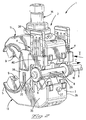
- figure 1 is a plan end view of an insulation piercing connector assembly about to receive an end-cable over which is mounted an end sealing cap;
- figure 2 is a perspective view of the connector assembly of figure 1, with the end cable inserted between clamping halves or jaws of the connector;
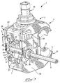
- figure 3 is a perspective view of the assembly of figure 2 with pre-termination retention members of the assembly moved to the retaining position holding the end cable to the connector;
- figure 4 is a plan end view of the assembly of figure 3;
- figure 5 is a perspective view of different size end sealing caps moulded together.
-
- Referring to the figures, a connector assembly 1 comprises an insulation piercing contact (IPC)
connector 2 for interconnecting a first through-cable or end-cable (not shown) to an end-cable 6. The through-cable may for example be a main cable, off which electrical power is tapped to a branch, tap, or distribution cable 6 (hereinafter "end-cable"). Alternatively, the IPC connector may interconnect two end-cables thereby acting as a splice. Both cables are comprised of inner conducting strands surrounded by an outer insulating layer. TheIPC connector 2 is provided with a pair ofopposed clamping halves FR 2 634 070, or US 5,015,198. Theclamping halves bolt 14 centrally positioned betweencable receiving sides IPC connector 2 will not be described in further detail except for the features relating to the improvements thereof. - The assembly further comprises an
end sealing cap 8 mountable over the end of the end-cable 6, and apre-termination retention device 4 mounted on theconnector 2 for holding the end cable and cap to the connector prior to electrical termination, as will be described in more detail further on. Theend cap 8 can be made of an elastomeric material such as a silicon based rubber, or a flexible plastic material that is injection moulded, and comprises a substantiallycylindrical cavity 16 extending therethrough for snugly receiving thecable end 6 therein through a cable receiving oropen end 18 until abutment with an opposed closed end 20 (see figures 2 and 5). Proximate theopen end 18 thecavity 16 may be provided with a plurality ofcircumferential sealing ribs 22 for providing a water tight seal against thecable 6. For caps made from a supple elastic material such as rubber, the inner diameter of thecylindrical cavity 16 may be slightly smaller than the outer diameter of the cable such that elastic compression of thesealing ribs 22 against the cable provides a tight seal. The elasticity of a rubber sealing cap also enables a single sealing cap to be utilised for cables of slightly different diameters. - A plurality of
end sealing caps 8, 8' as shown in figure 5, may be provided with the connector assembly 1 for use with different cable sizes, whereby to provide an economical connector assembly the differentend sealing caps 8, 8' may be moulded together such that they are integrally attached viabridging portions 24 and connected to thebridging portions 24 via thinbreakable portions 26 such that the desired end cap may be broken off for use in the assembly, as shown for example in figure 2. The sealing caps may be fixable provisionally to the connector by means of thehole 25 received in thestud 27 on the connector. - The end cap may also be made of a less resilient material such as a plastic, and for example partially filled with a sealing gel or grease that prevents the ingress of moisture by filling any hollow spaces within the
cavity 16 when the cap is mounted on the cable. - The end sealing cap is further provided with
retaining walls open end 18 and closedend 20 respectively, theretaining walls retention shoulders cylindrical body portion 32 of the sealing cap. Theretention shoulders opposed end faces retaining walls cap 8 with respect to the connector, and in particular with respect to the insulation piercing contact teeth 9 thereof. - Prior to termination the
end sealing cap 8 is thus slipped over the end of thecable 8 until abutment of the severed end of the cable against the closedend 20 of the sealing cap, and subsequently inserted between the clamping halves orjaws second side 7 as shown in figure 2) of theconnector 2. Insertion of the assembled sealingcap 8 andcable 6 is effected in a direction approximately perpendicular to the cable direction (C) as indicated by the orthogonal direction (T) shown in figure 1. Lateral insertion of thecable end 6 between thejaws - As the
cable 6 needs to be interconnected to another cable that is received on thefirst side 5 of the connector, it is advantageous to provisionally hold the connector and cable end together prior to tightening thebolt 14, which is effected by theretention members 4. Whilst two retention members are provided in the embodiment shown in figures 2-4, oneretention member 4 mounted to one of theconnector jaws 11 at eitherend retention member 4 comprises aretainer plate 38 movably received through aguide 40 securely attached to asupport 39 extending from one of the clampingjaws 13 of the connector. In this embodiment, thesupport 39 and guide 40 are integrally formed with the housing of thelower clamping jaw 13. Theguide 40 has a cavity extending therethrough for guiding theretainer plate 38 in the direction of movement (V) thereof which is orthogonal to a plane formed by the cable direction (C) and direction of insertion (T) of the cable end into the connector. Theretainer plate 38 is provided with a pair offlexible extensions 41 that extend from anactuation end 42 to a retainingend 44 of the plate, the ends 42, 44 at opposed ends of theretainer plate 38 with respect to the vertical direction (V) as viewed with respect to figure 1. Eachextension 41 is provided with a plurality ofteeth 46 on an outer edge thereof that are co-operable with teeth on respective inner edges of opposed sides of theguide 40 for retaining theretention plate 38 in theguide 40. In particular, theteeth 46 prevent the retainingplate 38 from being raised out of the retaining position shown in figure 3, which is achieved y depressing the retainer plate 38 (for example by manually pushing down the actuation end 42) until the opposed oblique clamping surfaces 48 of theretention end 44 clamp thecylindrical body portion 32 against thelower clamping jaw 13. The elasticity of theextensions 41 enable theretainer plate 38 to be depressed into the retaining position shown in figure 3 with theteeth 46 engaging co-operating teeth in theguide 40 like a ratchet. - The
retention end 44 of eachretainer plate 38 engages the sealingcap body 32 adjacent the respective retaining shoulders 30, 31 of the sealing cap in order to retain theend cable 6 and sealingcap 8 securely to the connector, particularly in the cable direction (C). - In view of the oblique (inwardly tapered and partially arcuate) surfaces 48 at the
retention end 44, the sealingcap body 32 is tightly clamped against theend cable 6 at the locations of the retainingplates 38, particularly since the cap is made of a flexible material, thereby ensuring a secure grip of theend cable 6 to the assembly prior to termination. Thecable 6 and sealingbody 32 are "wedged" between the pair ofresilient extensions 41. - It may be noted that the
extensions 41 extend from theactuation end 42 substantially as cantilever beams provided withhollow portions 50 to increase the flexibility thereof whilst providing a robust extension with a sufficientlylarge clamping edge 48. The assembled end cable and sealing cap provisionally retained to the connector in the pre-termination position shown in figure 3, can thus be handled by an operator for positioning another cable on the other side of the connector without concern about the need to position two cables simultaneously. This also ensures that when thebolt 14 is tightened and the clamping halves are moved together, the cables are correctly positioned between the insulation piercing contacts 9. The insulation piercing contact teeth of the connector are provided with a sufficient height to penetrate through thebody 32 of the sealing cap and subsequently through the insulation of the cable for contacting the inner conductor core of the cable. As thebody 32 of the sealing cap may be of a relatively thin compressible material, the insulation piercing teeth of standard connectors typically have a sufficient depth for piercing through the seal cap and insulating layer of the cable.
Claims (8)
- An electrical connector assembly (1) comprising an electrical insulation piercing connector (2) having a pair of clamping halves or jaws (11, 13), at least one of the jaws comprising at least one insulation piercing terminal having insulation piercing contacts (9) for piercing through an outer insulation layer of an electrical cable (6) and contacting inner conducting strands thereof, the assembly further comprising an end sealing cap (8) insertable over an end of the cable (6), wherein the end sealing cap (8) is adapted to be received in a direction transverse (T) to a direction (C) of the cable between the clamping halves (11, 13) such that the insulation piercing contacts (9) pierce through the end sealing cap (8) during connection to the cable.
- The assembly of claim 1 wherein end sealing cap (8) is provided with at least one retaining wall (28, 29) for locating the end sealing cap with respect to the connector (2) in the cable direction (C).
- The assembly of claim 2 wherein the sealing cap comprises at least a pair of said retaining walls (28, 29) separated by a distance (D) for positioning proximate or adjacent respective opposed ends (34, 35) of the connector with regards to the cable direction (C).
- The assembly of claim 2 or 3 wherein the sealing cap retaining walls (28,29) are in the shape of discs extending radially from a cylindrical body portion (32) of the sealing cap, thereby defining opposed retention shoulders (30, 31) respectively.
- The assembly of any one of the preceding claims wherein the assembly comprises a retention member (4) comprising a guide (40) securely fixed to one of the clamping jaws (13) and receiving a retaining plate (38) that is movable from a cable receiving position where the sealing cap (8) and end cable (6) can be inserted between the jaws (11, 13) of the connector to a retaining position where the cable and sealing cap are retained and positioned against said one of the clamping jaws (13) prior to termination of the connector.
- The assembly of the preceding claim wherein the retaining plate (13) comprises at least one flexible extension (41) having teeth (46) along an outer edge thereof co-operable with complementary teeth in the retaining guide (40) for holding the retaining plate (38) in the cable receiving and retaining positions respectively.
- The assembly of any one of the preceding claims wherein the connector comprises a pair of retention members (4) positioned respectively adjacent opposed ends (34,35) of the connector with regards to the cable direction (C).
- The assembly of any one of the preceding claims wherein a plurality of end sealing caps (8, 8') for receiving cables of different diameters are integrally moulded together via break away bridging portions (24).
Priority Applications (1)
| Application Number | Priority Date | Filing Date | Title |
|---|---|---|---|
| EP99112511A EP0969552B1 (en) | 1998-07-02 | 1999-07-01 | End cap for insulation piercing connectors |
Applications Claiming Priority (3)
| Application Number | Priority Date | Filing Date | Title |
|---|---|---|---|
| EP98401663 | 1998-07-02 | ||
| EP98401663 | 1998-07-02 | ||
| EP99112511A EP0969552B1 (en) | 1998-07-02 | 1999-07-01 | End cap for insulation piercing connectors |
Publications (2)
| Publication Number | Publication Date |
|---|---|
| EP0969552A1 true EP0969552A1 (en) | 2000-01-05 |
| EP0969552B1 EP0969552B1 (en) | 2002-10-30 |
Family
ID=26151657
Family Applications (1)
| Application Number | Title | Priority Date | Filing Date |
|---|---|---|---|
| EP99112511A Expired - Lifetime EP0969552B1 (en) | 1998-07-02 | 1999-07-01 | End cap for insulation piercing connectors |
Country Status (1)
| Country | Link |
|---|---|
| EP (1) | EP0969552B1 (en) |
Citations (7)
| Publication number | Priority date | Publication date | Assignee | Title |
|---|---|---|---|---|
| US1943020A (en) * | 1929-05-11 | 1934-01-09 | Karl V Johnson | Cable tap connecter |
| FR2601516A2 (en) * | 1984-06-15 | 1988-01-15 | Sicame Sa | Insulated branch connector for power cables |
| EP0282116A1 (en) * | 1987-02-26 | 1988-09-14 | Lovink-Terborg B.V. | Plastic branch terminal and coupling screw |
| EP0356329A1 (en) * | 1988-08-22 | 1990-02-28 | S I C A M E Societe Industrielle De Construction D'appareils Et De Materiel Electrique | Tapping assembly for a secondary cable to be connected to a main uninterrupted cable |
| US4985003A (en) * | 1988-05-13 | 1991-01-15 | S.I.C.A.M.E. Societe Industrielle De Construction D'appareils Et De Material Electrique | Branching electrical connector and spacer therefor |
| US5015198A (en) * | 1988-04-27 | 1991-05-14 | Niled S.A. | Terminal for connecting an insulated branch conductor to an insulated overhead line conductor |
| EP0653811A1 (en) * | 1993-11-17 | 1995-05-17 | Thomas & Betts Corporation | Electrical connector strain relief |
-
1999
- 1999-07-01 EP EP99112511A patent/EP0969552B1/en not_active Expired - Lifetime
Patent Citations (7)
| Publication number | Priority date | Publication date | Assignee | Title |
|---|---|---|---|---|
| US1943020A (en) * | 1929-05-11 | 1934-01-09 | Karl V Johnson | Cable tap connecter |
| FR2601516A2 (en) * | 1984-06-15 | 1988-01-15 | Sicame Sa | Insulated branch connector for power cables |
| EP0282116A1 (en) * | 1987-02-26 | 1988-09-14 | Lovink-Terborg B.V. | Plastic branch terminal and coupling screw |
| US5015198A (en) * | 1988-04-27 | 1991-05-14 | Niled S.A. | Terminal for connecting an insulated branch conductor to an insulated overhead line conductor |
| US4985003A (en) * | 1988-05-13 | 1991-01-15 | S.I.C.A.M.E. Societe Industrielle De Construction D'appareils Et De Material Electrique | Branching electrical connector and spacer therefor |
| EP0356329A1 (en) * | 1988-08-22 | 1990-02-28 | S I C A M E Societe Industrielle De Construction D'appareils Et De Materiel Electrique | Tapping assembly for a secondary cable to be connected to a main uninterrupted cable |
| EP0653811A1 (en) * | 1993-11-17 | 1995-05-17 | Thomas & Betts Corporation | Electrical connector strain relief |
Also Published As
| Publication number | Publication date |
|---|---|
| EP0969552B1 (en) | 2002-10-30 |
Similar Documents
| Publication | Publication Date | Title |
|---|---|---|
| US6106323A (en) | End cap for insulation piercing connectors | |
| US5683273A (en) | Mechanical splice connector for cable | |
| EP0657980B1 (en) | Enclosure with sealant for spliced coaxial cables | |
| KR890702280A (en) | Retention system for cable junction cover | |
| US3910672A (en) | Replacement cover for electrical wiring devices | |
| US3848956A (en) | Self-sealing underground tap connector | |
| WO1992015130A1 (en) | Terminal block | |
| US20150318637A1 (en) | Car charging connector | |
| US5545060A (en) | Clamping terminal unit | |
| US5691508A (en) | Enclosure for spliced multiconductor cable | |
| US4430523A (en) | Gripping jaw device for elongated members such as electrical conductors | |
| US6019627A (en) | Plug connector having a connecting cable | |
| US6036535A (en) | Cable end cap for power cable tap connector | |
| ES2916207T3 (en) | Cable connector assembly with releasable connectors | |
| HRP970632A2 (en) | Clamping device | |
| EP0969552B1 (en) | End cap for insulation piercing connectors | |
| US7942693B2 (en) | Power outlet with conductive socket contacts coupled to IDC contacts coupled to insulated conductors disposed in channels | |
| US3842191A (en) | Insulated wire splice | |
| US7347717B2 (en) | Insulation displacement system | |
| EP1012920B1 (en) | Cable connector | |
| GB2368197A (en) | Cable clamp for idc terminal connector | |
| CA1152175A (en) | Wire tap | |
| GB2185159A (en) | Cable connectors | |
| EP0803934A1 (en) | Electrical conductor connectors | |
| AU2006241314B2 (en) | Electrical connector with power socket |
Legal Events
| Date | Code | Title | Description |
|---|---|---|---|
| PUAI | Public reference made under article 153(3) epc to a published international application that has entered the european phase |
Free format text: ORIGINAL CODE: 0009012 |
|
| AK | Designated contracting states |
Kind code of ref document: A1 Designated state(s): DE FR GB |
|
| AX | Request for extension of the european patent |
Free format text: AL;LT;LV;MK;RO;SI |
|
| 17P | Request for examination filed |
Effective date: 20000630 |
|
| AKX | Designation fees paid |
Free format text: DE FR GB |
|
| GRAG | Despatch of communication of intention to grant |
Free format text: ORIGINAL CODE: EPIDOS AGRA |
|
| 17Q | First examination report despatched |
Effective date: 20020201 |
|
| GRAG | Despatch of communication of intention to grant |
Free format text: ORIGINAL CODE: EPIDOS AGRA |
|
| GRAH | Despatch of communication of intention to grant a patent |
Free format text: ORIGINAL CODE: EPIDOS IGRA |
|
| GRAH | Despatch of communication of intention to grant a patent |
Free format text: ORIGINAL CODE: EPIDOS IGRA |
|
| GRAA | (expected) grant |
Free format text: ORIGINAL CODE: 0009210 |
|
| AK | Designated contracting states |
Kind code of ref document: B1 Designated state(s): DE FR GB |
|
| REG | Reference to a national code |
Ref country code: GB Ref legal event code: FG4D |
|
| REF | Corresponds to: |
Ref document number: 69903693 Country of ref document: DE Date of ref document: 20021205 |
|
| ET | Fr: translation filed | ||
| PLBE | No opposition filed within time limit |
Free format text: ORIGINAL CODE: 0009261 |
|
| STAA | Information on the status of an ep patent application or granted ep patent |
Free format text: STATUS: NO OPPOSITION FILED WITHIN TIME LIMIT |
|
| 26N | No opposition filed |
Effective date: 20030731 |
|
| PGFP | Annual fee paid to national office [announced via postgrant information from national office to epo] |
Ref country code: DE Payment date: 20100728 Year of fee payment: 12 |
|
| PG25 | Lapsed in a contracting state [announced via postgrant information from national office to epo] |
Ref country code: DE Free format text: LAPSE BECAUSE OF NON-PAYMENT OF DUE FEES Effective date: 20120201 |
|
| REG | Reference to a national code |
Ref country code: DE Ref legal event code: R119 Ref document number: 69903693 Country of ref document: DE Effective date: 20120201 |
|
| REG | Reference to a national code |
Ref country code: FR Ref legal event code: PLFP Year of fee payment: 18 |
|
| REG | Reference to a national code |
Ref country code: FR Ref legal event code: PLFP Year of fee payment: 19 |
|
| REG | Reference to a national code |
Ref country code: FR Ref legal event code: PLFP Year of fee payment: 20 |
|
| PGFP | Annual fee paid to national office [announced via postgrant information from national office to epo] |
Ref country code: FR Payment date: 20180612 Year of fee payment: 20 |
|
| PGFP | Annual fee paid to national office [announced via postgrant information from national office to epo] |
Ref country code: GB Payment date: 20180627 Year of fee payment: 20 |
|
| REG | Reference to a national code |
Ref country code: GB Ref legal event code: PE20 Expiry date: 20190630 |
|
| PG25 | Lapsed in a contracting state [announced via postgrant information from national office to epo] |
Ref country code: GB Free format text: LAPSE BECAUSE OF EXPIRATION OF PROTECTION Effective date: 20190630 |