EP0968970B1 - Method and apparatus for tempering glass panels - Google Patents
Method and apparatus for tempering glass panels Download PDFInfo
- Publication number
- EP0968970B1 EP0968970B1 EP99660110A EP99660110A EP0968970B1 EP 0968970 B1 EP0968970 B1 EP 0968970B1 EP 99660110 A EP99660110 A EP 99660110A EP 99660110 A EP99660110 A EP 99660110A EP 0968970 B1 EP0968970 B1 EP 0968970B1
- Authority
- EP
- European Patent Office
- Prior art keywords
- orifices
- air
- fan air
- fan
- nozzle
- Prior art date
- Legal status (The legal status is an assumption and is not a legal conclusion. Google has not performed a legal analysis and makes no representation as to the accuracy of the status listed.)
- Expired - Lifetime
Links
- 239000011521 glass Substances 0.000 title claims description 30
- 238000005496 tempering Methods 0.000 title claims description 19
- 238000000034 method Methods 0.000 title claims description 14
- 238000001816 cooling Methods 0.000 claims description 19
- 238000005422 blasting Methods 0.000 claims description 14
- 230000000694 effects Effects 0.000 claims description 5
- 238000010438 heat treatment Methods 0.000 claims description 4
- 238000007599 discharging Methods 0.000 description 3
- 230000035882 stress Effects 0.000 description 3
- 239000005388 borosilicate glass Substances 0.000 description 2
- 238000000137 annealing Methods 0.000 description 1
- 230000000712 assembly Effects 0.000 description 1
- 238000000429 assembly Methods 0.000 description 1
- 230000004323 axial length Effects 0.000 description 1
- 230000009286 beneficial effect Effects 0.000 description 1
- 230000006835 compression Effects 0.000 description 1
- 238000007906 compression Methods 0.000 description 1
- 230000001419 dependent effect Effects 0.000 description 1
- 239000002184 metal Substances 0.000 description 1
- 230000008646 thermal stress Effects 0.000 description 1
Images

Classifications
-
- C—CHEMISTRY; METALLURGY
- C03—GLASS; MINERAL OR SLAG WOOL
- C03B—MANUFACTURE, SHAPING, OR SUPPLEMENTARY PROCESSES
- C03B27/00—Tempering or quenching glass products
- C03B27/04—Tempering or quenching glass products using gas
- C03B27/0404—Nozzles, blow heads, blowing units or their arrangements, specially adapted for flat or bent glass sheets
-
- C—CHEMISTRY; METALLURGY
- C03—GLASS; MINERAL OR SLAG WOOL
- C03B—MANUFACTURE, SHAPING, OR SUPPLEMENTARY PROCESSES
- C03B27/00—Tempering or quenching glass products
- C03B27/04—Tempering or quenching glass products using gas
- C03B27/044—Tempering or quenching glass products using gas for flat or bent glass sheets being in a horizontal position
Definitions
- the present invention relates to a method for tempering glass panels, said method comprising the steps of
- the invention relates also to an apparatus for tempering glass panels, said apparatus comprising:
- the Applicant's patent application EP-A-558912 discloses a nozzle assembly, which enables a concurrent use of compressor-produced jets of compressed air and fan-produced jets of fan air
- the relative disposition of compressed-air jets and fan air jets is not implemented in an optimal fashion in terms of making a common cooling station, along with its nozzles, suitable for both power tempering and after-cooling.
- the term power tempering refers to such a chilling power which has a coefficient of heat transfer of at least 600 W/m 2 K.
- the power tempering like this is required e.g. when tempering (without metal wires) is used for producing glass panels included in the fireproof category E30 or E60. The higher the stress achieved by tempering, the longer the glass is capable of withstanding the heat-induced annealing.
- the power tempering is also needed in the following cases. Glasses with a low coefficient of heat expansion, such as borosilicate glasses and also thin, less than 3 mm thick glasses require effective chilling in order to create thermal stresses needed in tempering (compression stress in the surface and tensile stress in the middle). On the other hand, the effective chilling requires a high coefficient of heat transfer.
- the tempering of borosilicate glasses and e.g. 2,5 mm thick glasses requires a coefficient of heat transfer of more than 1000 W/m 2 K. Prior to the present invention, the only way to reach such a high coefficient of heat transfer has been oil hardening.
- Patent publication US-A-4,913,720 discloses an apparatus, which comprises a separate chilling zone connected with compressed air upheld by means of a compressor, and an after-cooling zone provided with fan-produced jets of cooling air.
- the highest coefficient of heat transfer used in tests conducted according to the cited publication has been about 560 W/m 2 K, which is not sufficient for the purposes of the present invention.
- Patent publication GB-A-2,232,978 also discloses a two-phase cooling, wherein a compressor pressure is initially used for a higher coefficient of heat transfer. Even though the publication mentions that the coefficient of heat transfer is within the ranges of 300-1000 Kcal/m 2 x h x °C (equivalent to about 350-1160 W/m 2 K), said publication discloses no solution for achieving such a high coefficient of heat transfer.
- the highest coefficient of heat transfer used in the tabulated examples is 600 Kcal/m 2 x h x °C (equivalent to about 700 W/m 2 K), which has obviously been the highest coefficient of heat transfer reached by the test apparatus.
- An object of the invention is to provide a method and an apparatus of the above-mentioned type, capable of achieving a chilling process more effective than earlier in the same chilling station and by the same nozzle means which can be used for performing an after-cooling process which is lower in terms of its coefficient of heat transfer but massive in terms of its air volume and a relatively lengthy process.
- the apparatus shown in fig. 2 comprises a furnace 15, provided with heating elements 17 above and below a roll conveyor for heating a glass panel to a tempering temperature.
- the heated glass panel is carried by the roll conveyor into a cooling station 16, which functions both as a chilling station and as an after-cooling station.
- a cooling station 16 Above and below a conveyor plane constituted by the roll conveyor the station 16 is provided with cooling air boxes 1, 2, 9, which are connected on the one hand to a fan 11 and on the other hand to a compressed-air source 13 for a compressor 12 by way of a valve 14.
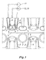
- the cooling air boxes and nozzle assemblies therefor are depicted in more detail in fig. 1.
- nozzle boxes 1 above a glass panel 5 supported by rolls 3 are structurally and in terms of nozzle systems thereof substantially identical to nozzle boxes 1 set below the glass panel 5. Therefore, the upper and lower nozzle boxes and the components thereof are indicated by the same reference numerals.
- the nozzle boxes 1 have covers 2 which are provided with fan air orificies 6 and 7, through which the air produced by a fan 11 discharges as air jets towards the surface of the glass panel 5.
- the nozzle orifices 7 have a diameter in the range of 5-7 mm, preferably about 6 mm.
- the orifices 6 have a diameter in the range of 3-5 mm, preferably about 4 mm.
- the cover thickness at the orifices 7 is e.g.
- the orifices 6, 7 will have a sufficient axial length for a nozzle effect, in order to produce directional jets.
- the orifices 7 along the edges of the cover 2 are directed obliquely away from each other in the flowing direction of the jets.
- the orifices 6 extend in a substantially orthgonal direction to the glass.
- the rows constituted by orifices 6 are located between the rows constituted by orifices 7.
- the number of orifices 6 can be substantially equal to that of orifices 7.
- the compressed-air boxes 9 are connected to a compressed-air source 13 for a compressor 12.
- the compressed-air boxes 9 are provided with screwed-on pipe nozzles 10, which extend towards the orifices 7.
- the pipe nozzles 10 have orifices 8 with a diameter within the range of 2,5-3,6 mm and, depending on the magnitude of applied overpressure, the air flow rate discharging through a given nozzle 10 is 3-6 I/s.
- the number of pipe nozzles is typically within the range of 400-500 pcs/m 2 .
- the air flow rate discharging through the pipe nozzles is typically within the range of 1,2-3 m 3 /m 2 /s.
- the overpressure required for this in the pressure chamber 9 is typically within the range of 1-2,5 bar.
- the pipe nozzles 10 have their orifices 8 opening in line with the enlarged bases of the fan air orifices 7.
- the outer sides of the nozzles 10 taper conically towards the nozzle tip.
- the tip of a given nozzle 10 is almost level with the inner surface of the cover 2 and may extend inside the orifice 7 or remain slightly outside the same. What is essential is that the tip of a given nozzle 10 does not restrict at least substantially the flow area of a respective compressed-air orifice 7, the orifices 7 being able to deliver fan air at a maximum rate while the compressed-air jets discharging from the orifices 8 intensify the flow of fan air through an ejector effect.
- the orifice 7 be given a diameter whose ratio to the diameter of the orifice 8 is within the range of 1,5-2,4, preferably within the range of 1,7-1,9.
- the chilling operation intensified with a method of the invention is carried out by blasting to the glass surface chilling air jets, which are partially produced by means of a compressor pressure through the pipe nozzles 10 and partially by means of the fan 11 through the orifices 6 and 7 present in the cover 2.
- the air flow rate to be blasted just through the pipe nozzles 10 is more than 1 m 3 /m 2 /s, typically within the range of 1,3-1,7 m 3 /m 2 /s.
- this volume of air is blasted from the orifices 8 through the fan air orifices 7 while blasting through all fan air orifices 6 and 7 quite a large volume of air produced by the fan 11.
- the after-cooling operation will be performed in the same cooling station 16 with cooling air jets discharged through the orifices 6 and 7 solely by means of the fan 11.
- the coefficient of heat transfer remains considerably lower as no compressor air is used. The reason for this is that the flow rates in the immediate vicinity of the glass surface are substantially reduced.
- the volume of air will be sufficient for a required after-cooling effect and such a volume of air can be produced advantageously and for a sufficiently long period by means of the fan 11.
Landscapes
- Chemical & Material Sciences (AREA)
- Physics & Mathematics (AREA)
- Thermal Sciences (AREA)
- Engineering & Computer Science (AREA)
- Materials Engineering (AREA)
- Organic Chemistry (AREA)
- Re-Forming, After-Treatment, Cutting And Transporting Of Glass Products (AREA)
Description
- The present invention relates to a method for tempering glass panels, said method comprising the steps of
- performing a chilling operation by blasting to the glass surface jets of a tempering gas, which are produced partially by a compressor pressure through pipe nozzles and partially by a fan through orifices present in a nozzle box cover; and
- performing an after-cooling operation in the same chilling station as the above-mentioned chilling operation by means of cooling air jets, which are produced exclusively by the fan through the orifices present in the nozzle box cover.
- The invention relates also to an apparatus for tempering glass panels, said apparatus comprising:
- a heating furnace for glass panels;
- a chilling station provided with rolls for carrying the glass panels;
- upper nozzle boxes whose cover is provided with fan air orifices for blasting downward air jets to the top surface of a glass panel;
- lower nozzle boxes whose cover is provided with fan air orifices for blasting upward air jets to the bottom surface of a glass panel;
- a fan in connection with the nozzle boxes for blasting fan air jets through said fan air orifices;
- compressed-air boxes within said upper and lower nozzle boxes;
- pipe nozzles in connection with the compressed-air boxes; and
- a compressed-air source, equipped with a compressor and connected with said compressed-air boxes for blasting jets of compressed air through the pipe nozzles.
- The Applicant's patent application EP-A-558912 discloses a nozzle assembly, which enables a concurrent use of compressor-produced jets of compressed air and fan-produced jets of fan air However, the relative disposition of compressed-air jets and fan air jets is not implemented in an optimal fashion in terms of making a common cooling station, along with its nozzles, suitable for both power tempering and after-cooling. In this context, the term power tempering refers to such a chilling power which has a coefficient of heat transfer of at least 600 W/m2K. The power tempering like this is required e.g. when tempering (without metal wires) is used for producing glass panels included in the fireproof category E30 or E60. The higher the stress achieved by tempering, the longer the glass is capable of withstanding the heat-induced annealing.
- The power tempering is also needed in the following cases. Glasses with a low coefficient of heat expansion, such as borosilicate glasses and also thin, less than 3 mm thick glasses require effective chilling in order to create thermal stresses needed in tempering (compression stress in the surface and tensile stress in the middle). On the other hand, the effective chilling requires a high coefficient of heat transfer. The tempering of borosilicate glasses and e.g. 2,5 mm thick glasses requires a coefficient of heat transfer of more than 1000 W/m2K. Prior to the present invention, the only way to reach such a high coefficient of heat transfer has been oil hardening.
- Patent publication US-A-4,913,720 discloses an apparatus, which comprises a separate chilling zone connected with compressed air upheld by means of a compressor, and an after-cooling zone provided with fan-produced jets of cooling air. The highest coefficient of heat transfer used in tests conducted according to the cited publication has been about 560 W/m2K, which is not sufficient for the purposes of the present invention.
- Patent publication GB-A-2,232,978 also discloses a two-phase cooling, wherein a compressor pressure is initially used for a higher coefficient of heat transfer. Even though the publication mentions that the coefficient of heat transfer is within the ranges of 300-1000 Kcal/m2 x h x °C (equivalent to about 350-1160 W/m2K), said publication discloses no solution for achieving such a high coefficient of heat transfer. The highest coefficient of heat transfer used in the tabulated examples is 600 Kcal/m2 x h x °C (equivalent to about 700 W/m2K), which has obviously been the highest coefficient of heat transfer reached by the test apparatus.
- An object of the invention is to provide a method and an apparatus of the above-mentioned type, capable of achieving a chilling process more effective than earlier in the same chilling station and by the same nozzle means which can be used for performing an after-cooling process which is lower in terms of its coefficient of heat transfer but massive in terms of its air volume and a relatively lengthy process.
- This object is achieved by means of a method set forth in the annexed
claim 1 and an apparatus set forth inclaim 3. Preferred embodiments of the invention are set forth in the dependent claims. - The invention will now be described in more detail by way of an exemplary embodiment with reference made to the accompanying drawings, in which
- fig. 1
- shows in a lateral view an essential section for an apparatus used for implementing the method, with one nozzle box shown in cross-section; and
- fig. 2
- shows schematically in a side view a tempering apparatus, which is
provided with a
chilling station 16 of the invention. - The apparatus shown in fig. 2 comprises a
furnace 15, provided withheating elements 17 above and below a roll conveyor for heating a glass panel to a tempering temperature. The heated glass panel is carried by the roll conveyor into acooling station 16, which functions both as a chilling station and as an after-cooling station. Above and below a conveyor plane constituted by the roll conveyor thestation 16 is provided withcooling air boxes fan 11 and on the other hand to a compressed-air source 13 for acompressor 12 by way of avalve 14. The cooling air boxes and nozzle assemblies therefor are depicted in more detail in fig. 1. - In fig. 1,
nozzle boxes 1 above aglass panel 5 supported byrolls 3 are structurally and in terms of nozzle systems thereof substantially identical tonozzle boxes 1 set below theglass panel 5. Therefore, the upper and lower nozzle boxes and the components thereof are indicated by the same reference numerals. Thenozzle boxes 1 havecovers 2 which are provided withfan air orificies 6 and 7, through which the air produced by afan 11 discharges as air jets towards the surface of theglass panel 5. The nozzle orifices 7 have a diameter in the range of 5-7 mm, preferably about 6 mm. Theorifices 6 have a diameter in the range of 3-5 mm, preferably about 4 mm. The cover thickness at the orifices 7 is e.g. 6 mm and at theorifices 6 it is 8-9 mm, whereby theorifices 6, 7 will have a sufficient axial length for a nozzle effect, in order to produce directional jets. The orifices 7 along the edges of thecover 2 are directed obliquely away from each other in the flowing direction of the jets. Theorifices 6 extend in a substantially orthgonal direction to the glass. The rows constituted byorifices 6 are located between the rows constituted by orifices 7. The number oforifices 6 can be substantially equal to that of orifices 7. - Within the
nozzle boxes air boxes 9, which are connected to a compressed-air source 13 for acompressor 12. The compressed-air boxes 9 are provided with screwed-onpipe nozzles 10, which extend towards the orifices 7. Thepipe nozzles 10 haveorifices 8 with a diameter within the range of 2,5-3,6 mm and, depending on the magnitude of applied overpressure, the air flow rate discharging through a givennozzle 10 is 3-6 I/s. The number of pipe nozzles is typically within the range of 400-500 pcs/m2. Thus, the air flow rate discharging through the pipe nozzles is typically within the range of 1,2-3 m3/m2/s. The overpressure required for this in thepressure chamber 9 is typically within the range of 1-2,5 bar. - The
pipe nozzles 10 have theirorifices 8 opening in line with the enlarged bases of the fan air orifices 7. The outer sides of thenozzles 10 taper conically towards the nozzle tip. The tip of a givennozzle 10 is almost level with the inner surface of thecover 2 and may extend inside the orifice 7 or remain slightly outside the same. What is essential is that the tip of a givennozzle 10 does not restrict at least substantially the flow area of a respective compressed-air orifice 7, the orifices 7 being able to deliver fan air at a maximum rate while the compressed-air jets discharging from theorifices 8 intensify the flow of fan air through an ejector effect. Regarding the cooperation between theorifices 7 and 8, it has been found beneficial that the orifice 7 be given a diameter whose ratio to the diameter of theorifice 8 is within the range of 1,5-2,4, preferably within the range of 1,7-1,9. - The chilling operation intensified with a method of the invention is carried out by blasting to the glass surface chilling air jets, which are partially produced by means of a compressor pressure through the
pipe nozzles 10 and partially by means of thefan 11 through theorifices 6 and 7 present in thecover 2. The air flow rate to be blasted just through thepipe nozzles 10 is more than 1 m3/m2/s, typically within the range of 1,3-1,7 m3/m2/s. Thus, this volume of air is blasted from theorifices 8 through the fan air orifices 7 while blasting through allfan air orifices 6 and 7 quite a large volume of air produced by thefan 11. - After the surfaces of a glass panel have cooled down sufficiently for tempering, the after-cooling operation will be performed in the
same cooling station 16 with cooling air jets discharged through theorifices 6 and 7 solely by means of thefan 11. The coefficient of heat transfer remains considerably lower as no compressor air is used. The reason for this is that the flow rates in the immediate vicinity of the glass surface are substantially reduced. However, the volume of air will be sufficient for a required after-cooling effect and such a volume of air can be produced advantageously and for a sufficiently long period by means of thefan 11. - The above-described method and apparatus offer a solution, whereby the power tempering and final cooling can be carried out in one and the same station. Prior to the present invention, this has required two separate stations with different nozzle systems.
Claims (7)
- A method for tempering glass panels, said method comprising the steps ofcharacterized in that, during the chilling operation, blasting is effected by the pipe nozzles (10) only through some (7) of the fan air orifices (6, 7) present in the nozzle box cover in such a way that the ejector effect of pipe nozzle jets intensifies the flow of fan air through the relevant fan air orifices (7), and that, in addition to this, the others (6) of the fan air orifices (6, 7) are used to blast exclusively fan air concurrently with said combined blasting of fan and compressor air.performing a chilling operation by blasting to the glass surface jets of a tempering gas, which are produced partially by a compressor pressure through pipe nozzles (10) and partially by a fan (11) through orifices (6, 7) present in a nozzle box cover (2); andperforming an after-cooling operation in the same chilling station (16) as the above-mentioned chilling operation by means of cooling air jets, which are produced exclusively by the fan (11) through the orifices (6, 7) present in the nozzle box cover (2),
- A method as set forth in claim 1, characterized in that the air flow rate to be blasted through the pipe nozzles (10) in the chilling operation is more than 1 m3/m2/s, preferably about 1,3-1,7 m3/m2/s.
- An apparatus for tempering glass panels, said apparatus comprising:characterized in that the pipe nozzles (10) open into some (7) of the fan air orifices (6, 7) and leave the others (6) of the fan air orifices (6, 7) unoccupied and in that the nozzle pipe orifices, having an orifice diameter of 2,5-3,6 mm, open in line with the enlarged bases of the fan air orifices with a diameter of 5-7 mm in such a way that the pipe nozzles (10) do not substantially restrict the cross-sectional area of the relevant fan air orifices (7) but provide the same with an ejector effect intensifying the flow of fan air.a heating furnace (15) for glass panels;a chilling station (16) provided with rolls (3) for carrying the glass panels;upper nozzle boxes (1) whose cover (2) is provided with fan air orifices (6, 7) for blasting downward air jets to the top surface of a glass panel (5);lower nozzle boxes (1) whose cover (2) is provided with fan air orifices (6, 7) for blasting upward air jets to the bottom surface of a glass panel;a fan (11) in connection with the nozzle boxes (1) for blasting fan air jets through said fan air orifices (6, 7).compressed-air boxes (9) within said upper and lower nozzle boxes (1);pipe nozzles (10) in connection with the compressed-air boxes (9); anda compressed-air source (13), equipped with a compressor (12) and connected with said compressed-air boxes (9) for blasting jets of compressed air through the pipe nozzles (10),
- An apparatus as set forth in claim 3, characterized in that the fan air orifice (7) has a diameter whose ratio to the diameter of an orifice (8) of the pipe nozzle (10) opening therein is 1,5-2,4.
- An apparatus as set forth in claim 3 or 4, characterized in that the fan air orifices (6) unoccupied by the pipe nozzles (10) are smaller in terms of their diameter than the fan air orifices (7) in communication with the pipe nozzles (10).
- An apparatus as set forth in any of claims 3-5, characterized in that the pipe nozzles (10) and the fan air orifices (7) in communication therewith are located adjacent to the outer edges of the nozzle box cover (2) and extend obliquely away from each other in the flowing direction of the jets, and that the fan air orifices (6) unoccupied by the pipe nozzles (10) extend essentially orthogonally to the glass and are located between rows of the fan air orifices (7) in communication with the pipe nozzles (10).
- An apparatus as set forth in any of claims 3-6, characterized in that the outer sides of the pipe nozzles (10) taper conically towards the nozzle tip, which is almost level with the inner surface of the cover (2) at the enlarged inlet of the fan air orifice (7).
Applications Claiming Priority (2)
| Application Number | Priority Date | Filing Date | Title |
|---|---|---|---|
| FI981502 | 1998-06-30 | ||
| FI981502A FI104422B (en) | 1998-06-30 | 1998-06-30 | Method and apparatus for curing glass sheets |
Publications (3)
| Publication Number | Publication Date |
|---|---|
| EP0968970A2 EP0968970A2 (en) | 2000-01-05 |
| EP0968970A3 EP0968970A3 (en) | 2000-05-17 |
| EP0968970B1 true EP0968970B1 (en) | 2003-08-27 |
Family
ID=8552101
Family Applications (1)
| Application Number | Title | Priority Date | Filing Date |
|---|---|---|---|
| EP99660110A Expired - Lifetime EP0968970B1 (en) | 1998-06-30 | 1999-06-18 | Method and apparatus for tempering glass panels |
Country Status (4)
| Country | Link |
|---|---|
| EP (1) | EP0968970B1 (en) |
| JP (1) | JP4489214B2 (en) |
| DE (1) | DE69910690T2 (en) |
| FI (1) | FI104422B (en) |
Families Citing this family (9)
| Publication number | Priority date | Publication date | Assignee | Title |
|---|---|---|---|---|
| KR101592045B1 (en) | 2008-03-31 | 2016-02-05 | 아사히 가라스 가부시키가이샤 | Air-cooled tempering device and air-cooled tempering method for glass plate |
| AT510416B1 (en) | 2011-04-18 | 2012-04-15 | Inova Lisec Technologiezentrum | METHOD AND DEVICE FOR HARDENING GLASS |
| EP2604582A1 (en) * | 2011-12-17 | 2013-06-19 | Cristales Automotrices de Jalisco, S.A. | Method and device for three-dimensional reforming of boards, in particular glass boards |
| KR101442029B1 (en) | 2013-06-26 | 2014-09-18 | 주식회사 이건창호 | Apparatus for manufacturing vacuum pair glass |
| US9573833B2 (en) * | 2014-03-31 | 2017-02-21 | Corning Incorporated | Method and lift jet floatation system for shaping thin glass |
| EP3196172B1 (en) * | 2016-01-20 | 2018-10-17 | South Glass Technology Co., Ltd | Device using cooling air for tempering glass |
| JP6608756B2 (en) * | 2016-04-05 | 2019-11-20 | Ykk Ap株式会社 | Method and apparatus for producing physically strengthened glass |
| DE102018123284A1 (en) * | 2018-09-21 | 2020-03-26 | sedak GmbH & Co. KG | Device for tempering glass panes |
| FI129685B (en) | 2020-06-08 | 2022-06-30 | Glaston Finland Oy | Method and device for tempering glass sheets |
Family Cites Families (2)
| Publication number | Priority date | Publication date | Assignee | Title |
|---|---|---|---|---|
| US4178414A (en) * | 1977-06-23 | 1979-12-11 | Triplex Safety Glass Company Limited | Method of toughening glass sheets |
| FI90046C (en) * | 1992-02-12 | 1993-12-27 | Tamglass Eng Oy | Nozzle arrangement for a flat glass curing oven |
-
1998
- 1998-06-30 FI FI981502A patent/FI104422B/en not_active IP Right Cessation
-
1999
- 1999-06-18 EP EP99660110A patent/EP0968970B1/en not_active Expired - Lifetime
- 1999-06-18 DE DE69910690T patent/DE69910690T2/en not_active Expired - Lifetime
- 1999-06-29 JP JP18424699A patent/JP4489214B2/en not_active Expired - Fee Related
Also Published As
| Publication number | Publication date |
|---|---|
| FI981502A7 (en) | 1999-12-31 |
| DE69910690T2 (en) | 2004-07-08 |
| EP0968970A2 (en) | 2000-01-05 |
| JP2000044264A (en) | 2000-02-15 |
| EP0968970A3 (en) | 2000-05-17 |
| FI981502A0 (en) | 1998-06-30 |
| DE69910690D1 (en) | 2003-10-02 |
| FI104422B (en) | 2000-01-31 |
| JP4489214B2 (en) | 2010-06-23 |
Similar Documents
| Publication | Publication Date | Title |
|---|---|---|
| EP2280097B1 (en) | Method of generating cracks in polycrystalline silicon rod and crack generating apparatus | |
| EP0968970A2 (en) | Method and apparatus for tempering glass panels | |
| US5236488A (en) | Method and apparatus for heat-strengthening glass sheets | |
| KR910000715B1 (en) | Compound blower head for cooling station of glass tempering device | |
| NZ286585A (en) | Forehearth for cooling molten glass: includes elongate trough with roof made from refractory block elements | |
| US4578102A (en) | Quenching or tempering by means of a two-phase jet | |
| EP1547980A1 (en) | Thermally tempered glass, and method and apparatus for manufactuing the glass | |
| JPH0359017B2 (en) | ||
| TWI749009B (en) | Apparatus for tempering glass sheets | |
| US6410887B1 (en) | Method for heating LowE glass panels in a tempering furnace | |
| EP0558912B1 (en) | Nozzle assembly for a flat-glass tempering machine | |
| EP3922611B1 (en) | Method and device for tempering glass sheets | |
| US4515622A (en) | Glass sheet quench including oppositely angled jets | |
| US4182619A (en) | Method of toughening glass sheets | |
| JPH0623068B2 (en) | How to strengthen flat glass | |
| EP3009410B1 (en) | Cooling tube assembly for cooling of the interior of a glass container | |
| KR20050005419A (en) | Method and Device for Producing Glass Fiber | |
| US2136158A (en) | Method of blowing meineral wool | |
| US5112377A (en) | Method of toughening glass sheet by quenching | |
| EP0416332B1 (en) | Method and apparatus for preventing the arching of glass sheets in the roller-equipped furnace of a horizontal tempering plant | |
| US6155822A (en) | Forced convection furnace and method for heating glass sheets | |
| US4886540A (en) | Blow back control device for a glass sheet tempering system | |
| US3454388A (en) | Oscillatory spray tempering apparatus | |
| DE19602184C2 (en) | Roller hearth tempering furnace with nozzle ribs for primarily convective heating of glass panes | |
| JPH02259025A (en) | Continuous annealing furnace |
Legal Events
| Date | Code | Title | Description |
|---|---|---|---|
| PUAI | Public reference made under article 153(3) epc to a published international application that has entered the european phase |
Free format text: ORIGINAL CODE: 0009012 |
|
| AK | Designated contracting states |
Kind code of ref document: A2 Designated state(s): DE FR GB IT |
|
| AX | Request for extension of the european patent |
Free format text: AL;LT;LV;MK;RO;SI |
|
| PUAL | Search report despatched |
Free format text: ORIGINAL CODE: 0009013 |
|
| AK | Designated contracting states |
Kind code of ref document: A3 Designated state(s): AT BE CH CY DE DK ES FI FR GB GR IE IT LI LU MC NL PT SE |
|
| AX | Request for extension of the european patent |
Free format text: AL;LT;LV;MK;RO;SI |
|
| 17P | Request for examination filed |
Effective date: 20001117 |
|
| AKX | Designation fees paid |
Free format text: DE FR GB IT |
|
| GRAH | Despatch of communication of intention to grant a patent |
Free format text: ORIGINAL CODE: EPIDOS IGRA |
|
| GRAH | Despatch of communication of intention to grant a patent |
Free format text: ORIGINAL CODE: EPIDOS IGRA |
|
| GRAA | (expected) grant |
Free format text: ORIGINAL CODE: 0009210 |
|
| AK | Designated contracting states |
Designated state(s): DE FR GB IT |
|
| REG | Reference to a national code |
Ref country code: GB Ref legal event code: FG4D |
|
| REF | Corresponds to: |
Ref document number: 69910690 Country of ref document: DE Date of ref document: 20031002 Kind code of ref document: P |
|
| ET | Fr: translation filed | ||
| PLBE | No opposition filed within time limit |
Free format text: ORIGINAL CODE: 0009261 |
|
| STAA | Information on the status of an ep patent application or granted ep patent |
Free format text: STATUS: NO OPPOSITION FILED WITHIN TIME LIMIT |
|
| 26N | No opposition filed |
Effective date: 20040528 |
|
| REG | Reference to a national code |
Ref country code: FR Ref legal event code: PLFP Year of fee payment: 18 |
|
| REG | Reference to a national code |
Ref country code: FR Ref legal event code: PLFP Year of fee payment: 19 |
|
| REG | Reference to a national code |
Ref country code: FR Ref legal event code: PLFP Year of fee payment: 20 |
|
| PGFP | Annual fee paid to national office [announced via postgrant information from national office to epo] |
Ref country code: DE Payment date: 20180625 Year of fee payment: 20 |
|
| PGFP | Annual fee paid to national office [announced via postgrant information from national office to epo] |
Ref country code: FR Payment date: 20180620 Year of fee payment: 20 |
|
| PGFP | Annual fee paid to national office [announced via postgrant information from national office to epo] |
Ref country code: GB Payment date: 20180620 Year of fee payment: 20 Ref country code: IT Payment date: 20180622 Year of fee payment: 20 |
|
| REG | Reference to a national code |
Ref country code: DE Ref legal event code: R071 Ref document number: 69910690 Country of ref document: DE |
|
| REG | Reference to a national code |
Ref country code: GB Ref legal event code: PE20 Expiry date: 20190617 |
|
| PG25 | Lapsed in a contracting state [announced via postgrant information from national office to epo] |
Ref country code: GB Free format text: LAPSE BECAUSE OF EXPIRATION OF PROTECTION Effective date: 20190617 |