EP0968952A2 - Retractable hose reel assemblies - Google Patents
Retractable hose reel assemblies Download PDFInfo
- Publication number
- EP0968952A2 EP0968952A2 EP99304819A EP99304819A EP0968952A2 EP 0968952 A2 EP0968952 A2 EP 0968952A2 EP 99304819 A EP99304819 A EP 99304819A EP 99304819 A EP99304819 A EP 99304819A EP 0968952 A2 EP0968952 A2 EP 0968952A2
- Authority
- EP
- European Patent Office
- Prior art keywords
- reel
- hose
- casing
- retaining means
- ratchet
- Prior art date
- Legal status (The legal status is an assumption and is not a legal conclusion. Google has not performed a legal analysis and makes no representation as to the accuracy of the status listed.)
- Granted
Links
Images

Classifications
-
- B—PERFORMING OPERATIONS; TRANSPORTING
- B65—CONVEYING; PACKING; STORING; HANDLING THIN OR FILAMENTARY MATERIAL
- B65H—HANDLING THIN OR FILAMENTARY MATERIAL, e.g. SHEETS, WEBS, CABLES
- B65H75/00—Storing webs, tapes, or filamentary material, e.g. on reels
- B65H75/02—Cores, formers, supports, or holders for coiled, wound, or folded material, e.g. reels, spindles, bobbins, cop tubes, cans, mandrels or chucks
- B65H75/34—Cores, formers, supports, or holders for coiled, wound, or folded material, e.g. reels, spindles, bobbins, cop tubes, cans, mandrels or chucks specially adapted or mounted for storing and repeatedly paying-out and re-storing lengths of material provided for particular purposes, e.g. anchored hoses, power cables
- B65H75/38—Cores, formers, supports, or holders for coiled, wound, or folded material, e.g. reels, spindles, bobbins, cop tubes, cans, mandrels or chucks specially adapted or mounted for storing and repeatedly paying-out and re-storing lengths of material provided for particular purposes, e.g. anchored hoses, power cables involving the use of a core or former internal to, and supporting, a stored package of material
- B65H75/44—Constructional details
- B65H75/4457—Arrangements of the frame or housing
- B65H75/446—Arrangements of the frame or housing for releasably or permanently attaching the frame to a wall, on a floor or on a post or the like
- B65H75/4463—Swivelling attachment
-
- B—PERFORMING OPERATIONS; TRANSPORTING
- B65—CONVEYING; PACKING; STORING; HANDLING THIN OR FILAMENTARY MATERIAL
- B65H—HANDLING THIN OR FILAMENTARY MATERIAL, e.g. SHEETS, WEBS, CABLES
- B65H75/00—Storing webs, tapes, or filamentary material, e.g. on reels
- B65H75/02—Cores, formers, supports, or holders for coiled, wound, or folded material, e.g. reels, spindles, bobbins, cop tubes, cans, mandrels or chucks
- B65H75/34—Cores, formers, supports, or holders for coiled, wound, or folded material, e.g. reels, spindles, bobbins, cop tubes, cans, mandrels or chucks specially adapted or mounted for storing and repeatedly paying-out and re-storing lengths of material provided for particular purposes, e.g. anchored hoses, power cables
- B65H75/38—Cores, formers, supports, or holders for coiled, wound, or folded material, e.g. reels, spindles, bobbins, cop tubes, cans, mandrels or chucks specially adapted or mounted for storing and repeatedly paying-out and re-storing lengths of material provided for particular purposes, e.g. anchored hoses, power cables involving the use of a core or former internal to, and supporting, a stored package of material
-
- B—PERFORMING OPERATIONS; TRANSPORTING
- B65—CONVEYING; PACKING; STORING; HANDLING THIN OR FILAMENTARY MATERIAL
- B65H—HANDLING THIN OR FILAMENTARY MATERIAL, e.g. SHEETS, WEBS, CABLES
- B65H75/00—Storing webs, tapes, or filamentary material, e.g. on reels
- B65H75/02—Cores, formers, supports, or holders for coiled, wound, or folded material, e.g. reels, spindles, bobbins, cop tubes, cans, mandrels or chucks
- B65H75/34—Cores, formers, supports, or holders for coiled, wound, or folded material, e.g. reels, spindles, bobbins, cop tubes, cans, mandrels or chucks specially adapted or mounted for storing and repeatedly paying-out and re-storing lengths of material provided for particular purposes, e.g. anchored hoses, power cables
- B65H75/38—Cores, formers, supports, or holders for coiled, wound, or folded material, e.g. reels, spindles, bobbins, cop tubes, cans, mandrels or chucks specially adapted or mounted for storing and repeatedly paying-out and re-storing lengths of material provided for particular purposes, e.g. anchored hoses, power cables involving the use of a core or former internal to, and supporting, a stored package of material
- B65H75/44—Constructional details
- B65H75/4418—Arrangements for stopping winding or unwinding; Arrangements for releasing the stop means
- B65H75/4428—Arrangements for stopping winding or unwinding; Arrangements for releasing the stop means acting on the reel or on a reel blocking mechanism
- B65H75/4431—Manual stop or release button
-
- B—PERFORMING OPERATIONS; TRANSPORTING
- B65—CONVEYING; PACKING; STORING; HANDLING THIN OR FILAMENTARY MATERIAL
- B65H—HANDLING THIN OR FILAMENTARY MATERIAL, e.g. SHEETS, WEBS, CABLES
- B65H75/00—Storing webs, tapes, or filamentary material, e.g. on reels
- B65H75/02—Cores, formers, supports, or holders for coiled, wound, or folded material, e.g. reels, spindles, bobbins, cop tubes, cans, mandrels or chucks
- B65H75/34—Cores, formers, supports, or holders for coiled, wound, or folded material, e.g. reels, spindles, bobbins, cop tubes, cans, mandrels or chucks specially adapted or mounted for storing and repeatedly paying-out and re-storing lengths of material provided for particular purposes, e.g. anchored hoses, power cables
- B65H75/38—Cores, formers, supports, or holders for coiled, wound, or folded material, e.g. reels, spindles, bobbins, cop tubes, cans, mandrels or chucks specially adapted or mounted for storing and repeatedly paying-out and re-storing lengths of material provided for particular purposes, e.g. anchored hoses, power cables involving the use of a core or former internal to, and supporting, a stored package of material
- B65H75/44—Constructional details
- B65H75/4457—Arrangements of the frame or housing
- B65H75/4471—Housing enclosing the reel
-
- B—PERFORMING OPERATIONS; TRANSPORTING
- B65—CONVEYING; PACKING; STORING; HANDLING THIN OR FILAMENTARY MATERIAL
- B65H—HANDLING THIN OR FILAMENTARY MATERIAL, e.g. SHEETS, WEBS, CABLES
- B65H2701/00—Handled material; Storage means
- B65H2701/30—Handled filamentary material
- B65H2701/33—Hollow or hose-like material
Definitions
- a known hose reel assembly comprises a casing providing a rotatable support for a reel around which the hose is wound.
- a spring is wound up to provide stored energy which is used for driving the reel in a direction corresponding to winding of the hose, to provide for automatic retraction of the hose onto the reel.
- the invention aims to provide a means of preventing withdrawal or unwinding movement of the hose from the reel, for example to prevent vandalism or to prevent a child pulling the hose from the reel and then possibly suffering discomfort or injury as a result of the automatic retraction of the hose.
- the second retaining means preferably include an actuating member manually movable between an operative locking position, in which the second retaining means prevent or limit unwinding movement of the reel, and an inoperative unlocked position in which the second retaining means are inoperative.
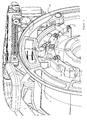
- the actuating member is preferably a pivotally movable lever incorporating or carrying a projecting end in the form of a crank, which, in the operative position, projects into the path of movement of the rotatable reel or a member carried thereby, in order to block rotation of the reel in an unwinding direction.
- the first retaining means may comprise a ratchet and pawl, one mounted on the casing and the other on the reel, wit the ratchet preferably being mounted on the reel and the pawl on the casing.
- the drive means may include a torsion spring in which energy is stored when the hose is unwound from the reel.
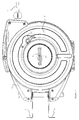
- the hose reel assembly comprises an outer casing 1 which supports a hose reel 2 capable of rotational movement with respect to the outer casing 1 about a horizontal axis indicated in end view at 3 in Figure 1.
- Mounting brackets 4 rigidly attached to the casing 1 enable the hose reel assembly to be mounted on a wall.
- a hose pipe, a projecting portion of which is indicated at 5 in Figure 1 is wound around a cylindrical hub of the reel 2, the hose pipe passing between spaced guides 7 in its passage on and off the reel 2.
- a torsion spring 8 is wound up, being driven by a toothed belt 9 passing around a smaller sprocket 10 mounted on the end of the torsion spring drive shaft and a larger sprocket (not shown) rotatable with the reel 2.
- the energy stored in the spring 8 is used to drive the reel, in an anti-clockwise direction when the reel assembly is viewed from the front as in the drawings, to rewind the hose on the reel 2.
- To store the complete length of hose on the reel 2 requires about twenty rotations of the reel 2.
- lever 20 can be rotated to lock the reel against unwinding movement, to provide a child lock or general purpose safety lock.
Landscapes
- Storing, Repeated Paying-Out, And Re-Storing Of Elongated Articles (AREA)
Abstract
Description
Claims (8)
- A retractable hose reel assembly comprising a casing (1), a reel (2) rotatably mounted with respect to the casing (1) and locking means (19, 20) for preventing or limiting rotational movement of the reel in a direction corresponding to unwinding of the hose from the reel.
- A retractable hose reel assembly comprising a casing (1), a reel (2) rotatably mounted in the casing (1), drive means (8) for rotating the reel (2) in a direction corresponding to winding of the hose on the reel, first retaining means (14, 18) for preventing or limiting rotational movement of the reel (2) in a winding direction and second retaining means (19, 20) for preventing or limiting rotational movement of the reel (2) in an unwinding direction.
- A hose reel assembly according to claim 2, wherein the second retaining means (19, 20) are capable of being rendered operative at a partially unwound condition of the hose or at a fully wound condition of the hose.
- A hose reel assembly according to claim 2 or 3, wherein the second retaining means include an actuating member (20) manually movable between an operative locking position, in which the second retaining means prevent or limit unwinding movement of the reel, and an inoperative unlocked position in which the second retaining means are inoperative.
- A hose reel assembly according to claim 4, wherein the actuating member is a pivotally movable lever (20) incorporating or carrying a projecting end in the form of a crank (22), which, in the operative position, projects into the path of movement of the rotatable reel (2) or a member carried thereby, in order to block rotation of the reel (2) in an unwinding direction.
- A hose reel assembly according to any of claims 2 to 5, wherein the first retaining means comprise a ratchet and pawl (14, 18), one mounted on the casing (1) and the other on the reel (2).
- A hose reel assembly according to claim 6, wherein the ratchet (14) is mounted on the reel (2) and the pawl (18) on the casing (1).
- A hose reel assembly according to claim 7, wherein the ratchet (14) carries projecting formations (19) with which the crank (22) is engageable in order to prevent or limit rotational movement of the reel (2) in an unwinding direction.
Applications Claiming Priority (2)
| Application Number | Priority Date | Filing Date | Title |
|---|---|---|---|
| GB9814439 | 1998-07-03 | ||
| GBGB9814439.7A GB9814439D0 (en) | 1998-07-03 | 1998-07-03 | Retractable hose reel assemblies |
Publications (3)
| Publication Number | Publication Date |
|---|---|
| EP0968952A2 true EP0968952A2 (en) | 2000-01-05 |
| EP0968952A3 EP0968952A3 (en) | 2000-09-20 |
| EP0968952B1 EP0968952B1 (en) | 2003-11-05 |
Family
ID=10834896
Family Applications (1)
| Application Number | Title | Priority Date | Filing Date |
|---|---|---|---|
| EP99304819A Expired - Lifetime EP0968952B1 (en) | 1998-07-03 | 1999-06-18 | Retractable hose reel assemblies |
Country Status (4)
| Country | Link |
|---|---|
| US (1) | US6416009B1 (en) |
| EP (1) | EP0968952B1 (en) |
| DE (1) | DE69912530T2 (en) |
| GB (1) | GB9814439D0 (en) |
Cited By (5)
| Publication number | Priority date | Publication date | Assignee | Title |
|---|---|---|---|---|
| WO2003086930A1 (en) * | 2002-04-15 | 2003-10-23 | Ab P H Nederman & Co | Reeling device and method of manufacturing such a device |
| DE10303600A1 (en) * | 2003-01-30 | 2004-08-12 | Robert Diebolder | Cable drum with braking device, has swivel-mounted braking key arranged on carrier frame and formed as rocker switch |
| WO2011059709A1 (en) | 2009-10-29 | 2011-05-19 | Graco Minnesota Inc. | Hose reel mounting tube constraint |
| WO2011114081A1 (en) * | 2010-03-16 | 2011-09-22 | Hozelock Limited | Hose reels |
| WO2012155960A1 (en) * | 2011-05-16 | 2012-11-22 | Alfred Kärcher Gmbh & Co. Kg | Hose retaining device |
Families Citing this family (16)
| Publication number | Priority date | Publication date | Assignee | Title |
|---|---|---|---|---|
| USD245836S (en) * | 1975-06-20 | 1977-09-20 | Deutsche Semperit Gummiwerk Ges. M.B.H. | Pneumatic tire tread and buttress |
| DE20008014U1 (en) * | 2000-05-05 | 2000-08-03 | Müller, Roland, 66453 Gersheim | Animal wrapping line |
| US20040107528A1 (en) * | 2002-08-27 | 2004-06-10 | Leclear Douglas D. | Vacuum system for a vehicle |
| US6857583B2 (en) * | 2002-09-26 | 2005-02-22 | Robert A. Attar | Boat/RV mounted pressure-wash system |
| US7266859B2 (en) * | 2002-12-02 | 2007-09-11 | Whirlpool Corporation | System of vacuum accessibility for a vehicle |
| US20060243282A1 (en) * | 2005-04-29 | 2006-11-02 | Sackman Susan M | Automated oxygen hose reel |
| ITMI20060622A1 (en) * | 2006-03-31 | 2007-10-01 | Claber Spa | PORTABLE FOLDER WITH AUTOMATIC STOP DEVICE |
| US7263784B1 (en) * | 2007-02-09 | 2007-09-04 | Shih-Lin Lee | Enhanced structure for measuring tape |
| US8746246B2 (en) * | 2009-06-04 | 2014-06-10 | Inspyrd Products Corporation | Apparatus and method for retrieval of tubing |
| US20120085135A1 (en) * | 2010-10-07 | 2012-04-12 | Billie Louden | Expandable handcuffs |
| US9016608B2 (en) | 2013-02-05 | 2015-04-28 | Intertek Industrial Corporation | Bi-directional locking retractor |
| US9199262B2 (en) * | 2013-05-20 | 2015-12-01 | Alto-Shaam, Inc. | Retractable spray hose with automatic shutoff |
| USD889944S1 (en) * | 2017-09-19 | 2020-07-14 | Claber S.P.A. | Hose winding device |
| US10987708B2 (en) * | 2019-01-28 | 2021-04-27 | Ridge Tool Company | Drain cleaning systems using sheath protected flexible shaft |
| USD966635S1 (en) * | 2020-06-04 | 2022-10-11 | Martin Cederberg | Pipe cleaning machine |
| US12504595B2 (en) * | 2021-12-03 | 2025-12-23 | Ppc Broadband Fiber Ltd. | Fiber reel and demarcation box assembly with reel controller and/or reversible cover |
Family Cites Families (22)
| Publication number | Priority date | Publication date | Assignee | Title |
|---|---|---|---|---|
| US737769A (en) * | 1901-10-28 | 1903-09-01 | Lewis C Preston | Fastening device. |
| US967601A (en) * | 1909-09-02 | 1910-08-16 | Thomas M Bovard | Clothes-line reel. |
| US993409A (en) * | 1910-06-20 | 1911-05-30 | Charles H Roderick | Clothes-line reel. |
| US1163444A (en) * | 1915-06-10 | 1915-12-07 | Edgar S Wiggins | Hanger for electric lamps. |
| US2249114A (en) * | 1940-06-05 | 1941-07-15 | Dallas H Coffman | Clothesline reel |
| US2659573A (en) * | 1951-01-26 | 1953-11-17 | Sr Joel D Smith | Safety belt cable take-up and shock absorber |
| US2775035A (en) * | 1955-05-16 | 1956-12-25 | Beresin Morris | Artificial teeth and method of assembling same |
| NL6614756A (en) * | 1966-10-20 | 1968-04-22 | ||
| US3550875A (en) * | 1968-06-28 | 1970-12-29 | American Safety Equip | Restraint apparatus |
| US3693596A (en) * | 1971-06-01 | 1972-09-26 | Joseph Croce | Dog leash retriever |
| US3853283A (en) * | 1973-06-04 | 1974-12-10 | J Croce | Retractable leash device |
| US3937418A (en) * | 1975-01-13 | 1976-02-10 | Lawrence Peska Associates, Inc. | Retractable dog leash |
| US4187962A (en) * | 1978-03-17 | 1980-02-12 | Henry Enterprises, Inc. | Fuel service tank with self-retracting hose reel |
| US4202510A (en) * | 1978-12-04 | 1980-05-13 | Stanish Walter F | Retractable pet leash |
| US4473197A (en) * | 1981-05-18 | 1984-09-25 | Mcgraw-Edison | Industrial cable reel apparatus having spring-loaded rewind motor |
| KR890005501Y1 (en) * | 1986-12-23 | 1989-08-21 | 주식회사 한국도량 | Winding tape stop |
| US4784221A (en) * | 1987-05-27 | 1988-11-15 | Share Jack H | Wellpoint system and reel |
| US4813627A (en) * | 1987-07-31 | 1989-03-21 | The Specialty Mfg. Co. | Rewindable hose reel |
| US5245761A (en) * | 1992-02-25 | 1993-09-21 | Arthur Waldherr | Locking mechanism for retractable tape |
| US5377626A (en) * | 1993-05-10 | 1995-01-03 | Kilsby; Celia | Lunge line controller |
| US5829154A (en) * | 1997-08-07 | 1998-11-03 | Lin; Lin Ping | Tape measure with flexible braking strips |
| US6082656A (en) * | 1999-01-29 | 2000-07-04 | Ericsson, Inc. | Electronic device with retractable cord |
-
1998
- 1998-07-03 GB GBGB9814439.7A patent/GB9814439D0/en not_active Ceased
-
1999
- 1999-06-18 EP EP99304819A patent/EP0968952B1/en not_active Expired - Lifetime
- 1999-06-18 DE DE69912530T patent/DE69912530T2/en not_active Expired - Lifetime
- 1999-06-28 US US09/340,752 patent/US6416009B1/en not_active Expired - Fee Related
Cited By (13)
| Publication number | Priority date | Publication date | Assignee | Title |
|---|---|---|---|---|
| WO2003086930A1 (en) * | 2002-04-15 | 2003-10-23 | Ab P H Nederman & Co | Reeling device and method of manufacturing such a device |
| DE10303600A1 (en) * | 2003-01-30 | 2004-08-12 | Robert Diebolder | Cable drum with braking device, has swivel-mounted braking key arranged on carrier frame and formed as rocker switch |
| DE10303600B4 (en) * | 2003-01-30 | 2016-05-25 | Robert Diebolder | Cable drum with braking device |
| CN102596774B (en) * | 2009-10-29 | 2014-11-12 | 格雷索明尼苏达有限公司 | Hose reel mounting tube constraint |
| WO2011059709A1 (en) | 2009-10-29 | 2011-05-19 | Graco Minnesota Inc. | Hose reel mounting tube constraint |
| CN102596774A (en) * | 2009-10-29 | 2012-07-18 | 格雷索明尼苏达有限公司 | Hose reel mounting tube constraint |
| TWI485098B (en) * | 2009-10-29 | 2015-05-21 | Graco Minnesota Inc | Hose reel mounting tube constraint |
| AU2010319905B2 (en) * | 2009-10-29 | 2014-05-15 | Graco Minnesota Inc. | Hose reel mounting tube constraint |
| WO2011114081A1 (en) * | 2010-03-16 | 2011-09-22 | Hozelock Limited | Hose reels |
| AU2010348750B2 (en) * | 2010-03-16 | 2015-11-26 | Sa Exel Industries | Hose reels |
| CN103534188A (en) * | 2011-05-16 | 2014-01-22 | 阿尔弗雷德·凯驰两合公司 | Hose Storage Equipment |
| CN103534188B (en) * | 2011-05-16 | 2015-11-25 | 阿尔弗雷德·凯驰两合公司 | Hose Storage Equipment |
| WO2012155960A1 (en) * | 2011-05-16 | 2012-11-22 | Alfred Kärcher Gmbh & Co. Kg | Hose retaining device |
Also Published As
| Publication number | Publication date |
|---|---|
| EP0968952B1 (en) | 2003-11-05 |
| EP0968952A3 (en) | 2000-09-20 |
| DE69912530T2 (en) | 2004-09-23 |
| GB9814439D0 (en) | 1998-09-02 |
| DE69912530D1 (en) | 2003-12-11 |
| US6416009B1 (en) | 2002-07-09 |
Similar Documents
| Publication | Publication Date | Title |
|---|---|---|
| EP0968952B1 (en) | Retractable hose reel assemblies | |
| US6293485B1 (en) | Two-stage retractable cord reel | |
| EP2126265B1 (en) | Control system for architectural coverings with reversible drive and single operating element | |
| US6158563A (en) | Winding mechanism | |
| JP3768585B2 (en) | Web retractor | |
| US4227661A (en) | Latching mechanism and winding apparatus including same | |
| US5683055A (en) | Quick rewind chalk line reel | |
| JP2000509679A (en) | Tightening lock | |
| JPH0415897Y2 (en) | ||
| JPS63117701A (en) | Winder safety apparatus of ski boots | |
| US11758902B2 (en) | Retractable duck decoy weight | |
| US4943011A (en) | Seat belt retractor with tension-reducing winding mechanism | |
| EP1167267B1 (en) | Improvement in or relating to hose reels | |
| US20080251625A1 (en) | Retractable Reeled Tape and Control Mechanism Therefor | |
| US3664599A (en) | Double locking retractable seat belt assembly | |
| CA1064452A (en) | Seat belt retracting and winding device | |
| JP5113189B2 (en) | Closure means for retaining door closure | |
| US3604654A (en) | Automatic seatbelt retractor with slip clutch | |
| FR2460141A1 (en) | AUTOMATIC DEVICE FOR RAPID LOCKING OF A SEAT BELT REEL | |
| JP4143931B2 (en) | Tension device for non-slip chain | |
| US4948065A (en) | Cable reel | |
| JP7369565B2 (en) | Tensioning device for snow chains and snow chains equipped with the device | |
| GB2475069A (en) | Reel automatic lock and rewind mechanism | |
| EP4554816B1 (en) | Retractable drive formation | |
| JPH0219032Y2 (en) |
Legal Events
| Date | Code | Title | Description |
|---|---|---|---|
| PUAI | Public reference made under article 153(3) epc to a published international application that has entered the european phase |
Free format text: ORIGINAL CODE: 0009012 |
|
| AK | Designated contracting states |
Kind code of ref document: A2 Designated state(s): DE FR GB |
|
| AX | Request for extension of the european patent |
Free format text: AL;LT;LV;MK;RO;SI |
|
| PUAL | Search report despatched |
Free format text: ORIGINAL CODE: 0009013 |
|
| AK | Designated contracting states |
Kind code of ref document: A3 Designated state(s): AT BE CH CY DE DK ES FI FR GB GR IE IT LI LU MC NL PT SE |
|
| AX | Request for extension of the european patent |
Free format text: AL;LT;LV;MK;RO;SI |
|
| 17P | Request for examination filed |
Effective date: 20010319 |
|
| AKX | Designation fees paid |
Free format text: DE FR GB |
|
| EL | Fr: translation of claims filed | ||
| 17Q | First examination report despatched |
Effective date: 20020830 |
|
| GRAH | Despatch of communication of intention to grant a patent |
Free format text: ORIGINAL CODE: EPIDOS IGRA |
|
| GRAS | Grant fee paid |
Free format text: ORIGINAL CODE: EPIDOSNIGR3 |
|
| GRAA | (expected) grant |
Free format text: ORIGINAL CODE: 0009210 |
|
| AK | Designated contracting states |
Kind code of ref document: B1 Designated state(s): DE FR GB |
|
| REG | Reference to a national code |
Ref country code: GB Ref legal event code: FG4D |
|
| REF | Corresponds to: |
Ref document number: 69912530 Country of ref document: DE Date of ref document: 20031211 Kind code of ref document: P |
|
| ET | Fr: translation filed | ||
| PLBE | No opposition filed within time limit |
Free format text: ORIGINAL CODE: 0009261 |
|
| STAA | Information on the status of an ep patent application or granted ep patent |
Free format text: STATUS: NO OPPOSITION FILED WITHIN TIME LIMIT |
|
| 26N | No opposition filed |
Effective date: 20040806 |
|
| REG | Reference to a national code |
Ref country code: FR Ref legal event code: ST |
|
| REG | Reference to a national code |
Ref country code: FR Ref legal event code: RN |
|
| REG | Reference to a national code |
Ref country code: FR Ref legal event code: FC |
|
| REG | Reference to a national code |
Ref country code: DE Ref legal event code: R082 Ref document number: 69912530 Country of ref document: DE Representative=s name: BERKENFELD, HELMUT, DIPL.-ING., DE |
|
| REG | Reference to a national code |
Ref country code: DE Ref legal event code: R082 Ref document number: 69912530 Country of ref document: DE Representative=s name: HWP INTELLECTUAL PROPERTY, DE Effective date: 20150508 Ref country code: DE Ref legal event code: R082 Ref document number: 69912530 Country of ref document: DE Representative=s name: BERKENFELD, HELMUT, DIPL.-ING., DE Effective date: 20150508 Ref country code: DE Ref legal event code: R081 Ref document number: 69912530 Country of ref document: DE Owner name: SA EXEL INDUSTRIES, FR Free format text: FORMER OWNER: HOZELOCK LTD., HADDENHAM, AYLESBURY, BUCKINGHAMSHIRE, GB Effective date: 20150508 |
|
| REG | Reference to a national code |
Ref country code: FR Ref legal event code: PLFP Year of fee payment: 17 |
|
| REG | Reference to a national code |
Ref country code: GB Ref legal event code: 732E Free format text: REGISTERED BETWEEN 20150611 AND 20150617 |
|
| REG | Reference to a national code |
Ref country code: FR Ref legal event code: CA Effective date: 20150723 |
|
| REG | Reference to a national code |
Ref country code: FR Ref legal event code: TP Owner name: SA EXEL INDUSTRIES, FR Effective date: 20150804 |
|
| REG | Reference to a national code |
Ref country code: DE Ref legal event code: R082 Ref document number: 69912530 Country of ref document: DE Representative=s name: HWP INTELLECTUAL PROPERTY, DE |
|
| REG | Reference to a national code |
Ref country code: FR Ref legal event code: PLFP Year of fee payment: 18 |
|
| REG | Reference to a national code |
Ref country code: FR Ref legal event code: PLFP Year of fee payment: 19 |
|
| REG | Reference to a national code |
Ref country code: FR Ref legal event code: PLFP Year of fee payment: 20 |
|
| PGFP | Annual fee paid to national office [announced via postgrant information from national office to epo] |
Ref country code: DE Payment date: 20180522 Year of fee payment: 20 |
|
| PGFP | Annual fee paid to national office [announced via postgrant information from national office to epo] |
Ref country code: FR Payment date: 20180525 Year of fee payment: 20 |
|
| PGFP | Annual fee paid to national office [announced via postgrant information from national office to epo] |
Ref country code: GB Payment date: 20180522 Year of fee payment: 20 |
|
| REG | Reference to a national code |
Ref country code: DE Ref legal event code: R071 Ref document number: 69912530 Country of ref document: DE |
|
| REG | Reference to a national code |
Ref country code: GB Ref legal event code: PE20 Expiry date: 20190617 |
|
| PG25 | Lapsed in a contracting state [announced via postgrant information from national office to epo] |
Ref country code: GB Free format text: LAPSE BECAUSE OF EXPIRATION OF PROTECTION Effective date: 20190617 |