EP0968923B1 - Packaging material sterilizing unit for a pourable food product packaging machine - Google Patents
Packaging material sterilizing unit for a pourable food product packaging machine Download PDFInfo
- Publication number
- EP0968923B1 EP0968923B1 EP98830392A EP98830392A EP0968923B1 EP 0968923 B1 EP0968923 B1 EP 0968923B1 EP 98830392 A EP98830392 A EP 98830392A EP 98830392 A EP98830392 A EP 98830392A EP 0968923 B1 EP0968923 B1 EP 0968923B1
- Authority
- EP
- European Patent Office
- Prior art keywords
- chamber
- temperature
- unit
- sterilizing agent
- controlling
- Prior art date
- Legal status (The legal status is an assumption and is not a legal conclusion. Google has not performed a legal analysis and makes no representation as to the accuracy of the status listed.)
- Expired - Lifetime
Links
Images
Classifications
-
- B—PERFORMING OPERATIONS; TRANSPORTING
- B65—CONVEYING; PACKING; STORING; HANDLING THIN OR FILAMENTARY MATERIAL
- B65B—MACHINES, APPARATUS OR DEVICES FOR, OR METHODS OF, PACKAGING ARTICLES OR MATERIALS; UNPACKING
- B65B55/00—Preserving, protecting or purifying packages or package contents in association with packaging
- B65B55/02—Sterilising, e.g. of complete packages
- B65B55/04—Sterilising wrappers or receptacles prior to, or during, packaging
- B65B55/10—Sterilising wrappers or receptacles prior to, or during, packaging by liquids or gases
- B65B55/103—Sterilising flat or tubular webs
Definitions
- the present invention relates to a sterilizing unit for a pourable food product packaging machine.
- Machines for packaging pourable food products such as fruit juice, wine, tomato sauce, pasteurized or preserved (UHT) milk, etc.
- the packages are formed from a continuous tube of packaging material defined by a longitudinally sealed strip.
- the packaging material has a multilayer structure comprising a layer of paper material coated on both sides with layers of heat-seal material, e.g. polyethylene.
- the packaging material comprises a layer of barrier material defined, for example, by an aluminium film, which is superimposed on a layer of heat-seal plastic material and is in turn coated with another layer of heat-seal plastic material defining the inner face of the package contacting the food product.
- Aseptic packages are produced by unwinding the strip of packaging material in steps off a reel and through a sterilizing unit, where it is sterilized, for example, by immersion in a chamber of liquid sterilizing agent such as a concentrated solution of hydrogen peroxide and water.
- liquid sterilizing agent such as a concentrated solution of hydrogen peroxide and water.
- the strip is then fed into an aseptic chamber where the sterilizing agent is evaporated by heating; and the strip is then folded into a cylinder and sealed longitudinally to form, in known manner, a continuous vertical longitudinally sealed tube. That is, the tube of packaging material forms an extension of the aseptic chamber, and is filled continuously with the pourable food product and fed to a forming and (transverse) sealing unit for forming the individual packages, and which grips the tube between pairs of jaws for transversely sealing the tube into pillow packs.
- the pillow packs are separated by cutting the sealing portion in between the packs, and are then transferred to a final folding station where they are folded mechanically into the final shape.
- the sterilizing unit referred to above comprises a chamber containing the sterilizing agent through which the strip is fed continuously.
- the sterilizing chamber conveniently comprises two parallel vertical branches connected to each other at the bottom to define a U-shaped path, the length of which depends on the traveling speed of the strip to allow enough time to process the packaging material.
- the sterilizing agent must be maintained at a high temperature, e.g. of about 70°C. In known sterilizing units, this is normally achieved by forming the walls of the sterilizing chamber with a first gap, which is filled, in use, with water recirculated through a thermostatically controlled electric heater.
- the packaging material is completely impermeable to the sterilizing agent on the polyethylene-coated faces of the strip, the layer of paper material is exposed along the edges of the strip and fairly absorbent; and what is known in the trade as “edge wicking" (edge absorption) is maintained within acceptable limits providing the strip is kept a limited length of time in the sterilizing chamber, as is the case when the machine is operating normally.
- the sterilizing chamber must be emptied immediately. Otherwise, the sterilizing agent penetrates the edges of the paper layer and, if the edge portion is penetrated to a width of a few millimeters, inevitably impairs subsequent longitudinal sealing of the strip to form the tube of packaging material as described above.
- edge wicking tends to occur anyway on known machines, despite the sterilizing chamber being emptied.
- sterilizing units have been devised in which, before being fed into the sterilizing chamber, the sterilizing agent is heated by circulating it inside a second gap located outside the walls of the sterilizing chamber and enabling heat exchange with the water inside the first gap.
- auxiliary heat exchanger using cold water from the mains as coolant to cool the water controlling the temperature of the sterilizing chamber before starting the machine, i.e. before feeding the sterilizing agent into the chamber.
- the water can only be cooled after preheating the sterilizing agent, which is preheated using the same water as heating fluid, restarting the machine takes a fairly long time, typically as long as 7-8 minutes, which in some cases is even longer than the actual downtime of the machine.
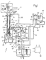
- Number 1 in Figure 1 indicates as a whole a sterilizing unit for sterilizing a strip 2 of packaging material for a pourable food product packaging machine. Strip 2 is fed to unit 1 off a reel in known manner not shown.
- Unit 1 substantially comprises a U-shaped sterilizing chamber 3, or bath, for containing a liquid sterilizing agent, e.g. a 30% solution of hydrogen peroxide (H 2 O 2 ) and water (hereinafter referred to simply as "the peroxide").
- Chamber 3 is defined by a vertical inlet conduit 4 and a vertical outlet conduit 5 having respective top openings 6 and 7 and connected to each other at the bottom by a bottom portion 5 of chamber 3 housing a horizontal-axis transmission roller 8.
- Strip 2 therefore defines, inside chamber 3, a U-shaped path P, the length of which depends on the traveling speed of the strip to ensure the packaging material is kept long enough in the peroxide.
- Sterilizing chamber 3 forms part of a peroxide control circuit 10, which also comprises a peroxide collecting tank 11; a conduit 12 by which to fill/empty chamber 3; a pump 13 immersed in tank 11 and driven by an electric motor 14; a delivery conduit 15 connecting the delivery side of pump 13 to conduit 12 via a valve 16; and a drain pipe 17 connecting conduit 12 to tank 11 via a two-way, two-position, normally-open valve 18 for safety reasons (chamber 3 is emptied in the event of an electric system fault).
- a peroxide control circuit 10 also comprises a peroxide collecting tank 11; a conduit 12 by which to fill/empty chamber 3; a pump 13 immersed in tank 11 and driven by an electric motor 14; a delivery conduit 15 connecting the delivery side of pump 13 to conduit 12 via a valve 16; and a drain pipe 17 connecting conduit 12 to tank 11 via a two-way, two-position, normally-open valve 18 for safety reasons (chamber 3 is emptied in the event of an electric system fault).
- Valve 16 is preferably a two-way, two-position, normally-open type, but with an on/off member (not shown) allowing residual leakage in the closed position, as explained later on.
- an on/off member (not shown)
- a commercial valve may be used, and a hole of appropriate size formed in the on/off member.
- Peroxide circuit 10 also comprises a recirculating conduit 20 connected to tank 11, and which communicates with an overflow 21 formed in the top portion of inlet conduit 4 of chamber 3 to determine the maximum level of peroxide in chamber 3.
- Unit 1 also comprises a system 25 for controlling the temperature of the peroxide in chamber 3.
- system 25 is hydraulic, and comprises a heat exchanger 26 using hot water as the operating fluid by which to exchange heat with the peroxide.
- One phase of exchanger 26 is defined by chamber 3 itself, and the other phase comprises two gaps 27a, 27b formed in the walls of conduits 4 and 5 of chamber 3, and which are associated with a hydraulic circuit 28 for controlling the temperature of chamber 3.
- circuit 28 comprises a pump 29 having a delivery conduit 30 to which are connected, in series with each other, a phase 31 of a cooling heat exchanger 32, as explained later on, and an electric resistor heater 33, the output of which is in turn connected to the bottom inlet 34 of gap 27a.
- Gaps 27a and 27b are connected to each other at the respective top ends by a conduit 35.
- Pump 29 also has an intake conduit 37 connected to the bottom outlet 36 of gap 27b.
- Circuit 28 is associated with a cooling circuit 40 using cold water from the mains as the operating fluid.
- Circuit 40 comprises an inlet conduit 41 connected, via a two-way, two-position, normally-closed on/off valve 42, to a second phase 43 of exchanger 32, flowing in the opposite direction to phase 31; and the outlet of second phase 43 of exchanger 32 is connected to a water drain conduit 44.
- unit 1 also comprises a peroxide preheating system 45.
- System 45 substantially comprises a countercurrent heat exchanger 46 using water as the operating fluid. More specifically, exchanger 46 has a peroxide inlet 47 connected to the delivery conduit 15 of pump 13; a peroxide outlet 48 connected to recirculating conduit 20; and a water phase connected in series with a heating circuit 49 and having an inlet 50 and an outlet 51.
- Circuit 49 substantially comprises a circulating pump 52, in turn comprising an intake conduit 55 connected to outlet 51 of heat exchanger 46, and a delivery conduit 56 connected to an electric resistor heater 57 in turn connected at the output to inlet 50 of exchanger 46.
- Intake conduits 37, 55 of respective pumps 29, 52 are connected by respective conduits 58, 59 to a filler conduit 60 and to a bleed conduit 61, which are in turn connectable to the water mains by respective taps 62, 63; and branch connected to filler conduit 60 are a water/compressed air accumulator 64 for pressure compensating circuits 28, 49, and a maximum-pressure valve 65 connected at the discharge to drain conduit 44.
- Pumps 13, 29, 52, valves 16, 18, 42 and the resistors of electric heaters 33, 57 are controlled by a control unit 66 in response to input signals Si received from process sensors comprising, in particular, a sensor for detecting the temperature of the water in gap 27b, a sensor for detecting the temperature of the peroxide in chamber 3, and a sensor for detecting the temperature of the peroxide in tank 11.
- Unit 1 operates as follows.
- chamber 3 When cold starting, chamber 3 is empty, all the peroxide is contained in tank 11, and pump 13 is energized to feed a large amount of peroxide, e.g. about 50 l/min, through heat exchanger 46.
- Filler valve 16 is closed, but, as already stated, allows a small amount of leakage (a few l/min) to conduit 12, and drain valve 18 is open, so that chamber 3 is not filled until the best cycle-start conditions are achieved, pending which, pumps 29 and 52 circulate water through respective heaters 33, 57.
- the cycle-start conditions are, for example, 72°C for the water in circuit 28, and 75°C for the peroxide in tank 11 (fill temperature). In this case, the water temperature is kept fairly high, since, chamber 3 and strip 2 being dry, there is substantially no risk of edge wicking, whereas it is important to prevent an undesired first-fill fall in temperature of the peroxide due to heat loss in the as yet cold pipes.
- valve 16 is opened and valve 18 closed, so that chamber 3 is filled rapidly with peroxide, and valve 16 is again closed once the chamber is filled.
- the temperature of the peroxide is maintained at a minimum of 73°C both in chamber 3 and tank 11; and, in the event either of the above temperatures falls below the predetermined threshold, a heating cycle is activated by circuit 28 and circuit 49 respectively.
- Pump 13 operates constantly to maintain a continuous flow through exchanger 46 (heater 57, however, is normally off at this stage) and a continuous leakage of peroxide - conveniently a few liters a minute - through valve 16 to compensate for any peroxide losses in chamber 3 caused by outfeed of the wet strip 2, and also to keep pipe 12 and the bottom of chamber 3 hot. Any surplus peroxide flows out of chamber 3 through overflow 21 and back into tank 11 along recirculating conduit 20. Also pumps 29 and 52 operate constantly. The temperature of the peroxide in chamber 3 is controlled in conventional manner by circuit 28. If the temperature in chamber 3 falls below the threshold value, heater 33 is activated to heat the water in gaps 27a, 27b and so "actively lag" chamber 3. At this stage, valve 42 of cooling circuit 40 is kept closed.
- heater 57 is activated.
- control unit 66 opens valve 18 to rapidly empty chamber 3.
- a cooling cycle to cool chamber 3 to less than the operating temperature (e.g. 63°C) and a heating cycle to heat the peroxide to the fill temperature (e.g. 75°C) are commenced simultaneously.
- Chamber 3 is cooled by deactivating heater 33 and activating cooling circuit 40 by opening valve 42; and the peroxide is heated by activating heater 57.
- cooling chamber 3 and preheating the peroxide to a higher temperature prevent the vapour inside chamber 3 from condensing when chamber 3 is filled again. Even after a short stoppage, during which chamber 3 is undoubtedly saturated, the machine may be restarted rapidly.
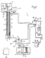
- FIG. 2 shows a further embodiment of a sterilizing unit in accordance with the present invention and indicated as a whole by 1'.
- unit 1' is only described insofar as it differs from unit 1, and using the same numbering system for any parts identical or corresponding to those already described.
- Unit 1' differs from unit 1 by system 25 for controlling the temperature in chamber 3 being electric as opposed to hydraulic. More specifically, in place of gaps 27a, 27b, chamber 3 is surrounded by four electric heaters 70 controlled by unit 66 and fitted externally in pairs to the walls of respective conduits 4, 5.
- chamber 3 is cooled by deactivating heaters 70 and blowing into chamber 3, by means of a forced ventilation circuit 71 (shown schematically in Figure 2), sterile air at a lower temperature than chamber 3.
- a forced ventilation circuit 71 shown schematically in Figure 2
- chamber 3 may be cooled by simply deactivating electric heaters 70.
Landscapes
- Engineering & Computer Science (AREA)
- Mechanical Engineering (AREA)
- Apparatus For Disinfection Or Sterilisation (AREA)
- Packages (AREA)
- Food Preservation Except Freezing, Refrigeration, And Drying (AREA)
- Containers And Plastic Fillers For Packaging (AREA)
- General Preparation And Processing Of Foods (AREA)
Abstract
Description
- The present invention relates to a sterilizing unit for a pourable food product packaging machine.
- Machines for packaging pourable food products, such as fruit juice, wine, tomato sauce, pasteurized or preserved (UHT) milk, etc., are known in which the packages are formed from a continuous tube of packaging material defined by a longitudinally sealed strip.
- The packaging material has a multilayer structure comprising a layer of paper material coated on both sides with layers of heat-seal material, e.g. polyethylene. For aseptic packaging of preserved products such as UHT milk, the packaging material comprises a layer of barrier material defined, for example, by an aluminium film, which is superimposed on a layer of heat-seal plastic material and is in turn coated with another layer of heat-seal plastic material defining the inner face of the package contacting the food product.
- Aseptic packages are produced by unwinding the strip of packaging material in steps off a reel and through a sterilizing unit, where it is sterilized, for example, by immersion in a chamber of liquid sterilizing agent such as a concentrated solution of hydrogen peroxide and water.
- The strip is then fed into an aseptic chamber where the sterilizing agent is evaporated by heating; and the strip is then folded into a cylinder and sealed longitudinally to form, in known manner, a continuous vertical longitudinally sealed tube. That is, the tube of packaging material forms an extension of the aseptic chamber, and is filled continuously with the pourable food product and fed to a forming and (transverse) sealing unit for forming the individual packages, and which grips the tube between pairs of jaws for transversely sealing the tube into pillow packs.
- The pillow packs are separated by cutting the sealing portion in between the packs, and are then transferred to a final folding station where they are folded mechanically into the final shape.
- More specifically, the sterilizing unit referred to above comprises a chamber containing the sterilizing agent through which the strip is fed continuously. The sterilizing chamber conveniently comprises two parallel vertical branches connected to each other at the bottom to define a U-shaped path, the length of which depends on the traveling speed of the strip to allow enough time to process the packaging material. To effectively process the packaging material in a relatively short space of time, e.g. about seven seconds, and so reduce the size of the sterilizing chamber, the sterilizing agent must be maintained at a high temperature, e.g. of about 70°C. In known sterilizing units, this is normally achieved by forming the walls of the sterilizing chamber with a first gap, which is filled, in use, with water recirculated through a thermostatically controlled electric heater.
- Whereas the packaging material is completely impermeable to the sterilizing agent on the polyethylene-coated faces of the strip, the layer of paper material is exposed along the edges of the strip and fairly absorbent; and what is known in the trade as "edge wicking" (edge absorption) is maintained within acceptable limits providing the strip is kept a limited length of time in the sterilizing chamber, as is the case when the machine is operating normally.
- Should the machine, however, be arrested for any reason, the sterilizing chamber must be emptied immediately. Otherwise, the sterilizing agent penetrates the edges of the paper layer and, if the edge portion is penetrated to a width of a few millimeters, inevitably impairs subsequent longitudinal sealing of the strip to form the tube of packaging material as described above.
- Following stoppage, and particularly when restarting the machine after a short stoppage, edge wicking tends to occur anyway on known machines, despite the sterilizing chamber being emptied.
- In-depth research into the phenomenon has revealed several causes:
- the porosity of the paper material : for production cost reasons, this can only be reduced to a certain extent;
- hydrostatic pressure : this is also difficult to reduce, in that, being dependent on the necessary processing time, the height of the U-shaped sterilizing chamber can only be reduced by altering the structure of the sterilizing unit, which obviously involves complications in terms of the system as a whole; and
- the temperature of the sterilizing chamber during stoppage, and of the sterilizing agent when fed back into the chamber. In particular, edge wicking has been found to be seriously affected by any difference, even of only a few degrees, between the temperature inside the chamber during stoppage and the temperature of the sterilizing agent fed back into the chamber. In known machines, such a difference in temperature is caused by the temperature of the chamber tending to rise once the chamber is emptied during stoppage, on account of the inevitable delay in the thermostat responding to the reduction in thermal absorption when the chamber is emptied. As a result, the temperature inside the chamber typically increases to at least 80°C, so that the sterilizing agent remaining on the walls of the chamber and in the paper material tends to evaporate, thus producing saturated vapour inside the chamber so that the pores of the paper material contain a saturated air/vapour mixture.
- When the liquid sterilizing agent is fed back in at a lower temperature (due to dissipation, the temperature of the liquid fed back into the chamber is at best a few degrees lower than the liquid inside the chamber when the machine was arrested), the temperature of the strip and therefore of the air-vapour mixture inside the pores is reduced: the effect of this reduction is practically negligible as regards the air, which undergoes a reduction in volume of only a few percent, but is considerably more serious as regards the vapour, which condenses to assume, in the liquid state, a much smaller volume. This drastic reduction in volume produces a strong "suction" effect, which draws the sterilizing agent into the pores of the paper material, and which is the main cause of the edge wicking phenomenon.
- By way of a solution to the problem, which is less serious during prolonged stoppages, due to evaporation of the residual liquid and a reduction in relative humidity inside the chamber, sterilizing units have been devised in which, before being fed into the sterilizing chamber, the sterilizing agent is heated by circulating it inside a second gap located outside the walls of the sterilizing chamber and enabling heat exchange with the water inside the first gap.
- Use is also made of an auxiliary heat exchanger using cold water from the mains as coolant to cool the water controlling the temperature of the sterilizing chamber before starting the machine, i.e. before feeding the sterilizing agent into the chamber. As the water, however, can only be cooled after preheating the sterilizing agent, which is preheated using the same water as heating fluid, restarting the machine takes a fairly long time, typically as long as 7-8 minutes, which in some cases is even longer than the actual downtime of the machine.
- In view of the extremely high output rate of packaging machines, such holdups result in considerable cost in terms of lost production.
- It is an object of the present invention to provide a unit for sterilizing strip packaging material for a pourable food product packaging machine, designed to eliminate the aforementioned drawbacks typically associated with known machines.
- According to the present invention, there is provided a sterilizing unit as claimed in Claim 1.
- Two preferred non-limiting embodiments of the present invention will be described by way of example with reference to the accompanying drawings, in which:
- Figure 1 shows a circuit diagram of a first embodiment of the invention;
- Figure 2 shows a circuit diagram of a second embodiment of the invention.
-
- Number 1 in Figure 1 indicates as a whole a sterilizing unit for sterilizing a strip 2 of packaging material for a pourable food product packaging machine. Strip 2 is fed to unit 1 off a reel in known manner not shown.
- Unit 1 substantially comprises a
U-shaped sterilizing chamber 3, or bath, for containing a liquid sterilizing agent, e.g. a 30% solution of hydrogen peroxide (H2O2) and water (hereinafter referred to simply as "the peroxide").Chamber 3 is defined by avertical inlet conduit 4 and avertical outlet conduit 5 having respectivetop openings 6 and 7 and connected to each other at the bottom by abottom portion 5 ofchamber 3 housing a horizontal-axis transmission roller 8. Strip 2 therefore defines, insidechamber 3, a U-shaped path P, the length of which depends on the traveling speed of the strip to ensure the packaging material is kept long enough in the peroxide. - Sterilizing
chamber 3 forms part of aperoxide control circuit 10, which also comprises aperoxide collecting tank 11; aconduit 12 by which to fill/empty chamber 3; apump 13 immersed intank 11 and driven by anelectric motor 14; adelivery conduit 15 connecting the delivery side ofpump 13 to conduit 12 via avalve 16; and adrain pipe 17 connectingconduit 12 totank 11 via a two-way, two-position, normally-open valve 18 for safety reasons (chamber 3 is emptied in the event of an electric system fault). - Valve 16 is preferably a two-way, two-position, normally-open type, but with an on/off member (not shown) allowing residual leakage in the closed position, as explained later on. For which purpose, a commercial valve may be used, and a hole of appropriate size formed in the on/off member.
-
Peroxide circuit 10 also comprises a recirculatingconduit 20 connected totank 11, and which communicates with anoverflow 21 formed in the top portion ofinlet conduit 4 ofchamber 3 to determine the maximum level of peroxide inchamber 3. - Unit 1 also comprises a
system 25 for controlling the temperature of the peroxide inchamber 3. In the Figure 1 embodiment,system 25 is hydraulic, and comprises aheat exchanger 26 using hot water as the operating fluid by which to exchange heat with the peroxide. One phase ofexchanger 26 is defined bychamber 3 itself, and the other phase comprises twogaps conduits chamber 3, and which are associated with ahydraulic circuit 28 for controlling the temperature ofchamber 3. - More specifically,
circuit 28 comprises apump 29 having adelivery conduit 30 to which are connected, in series with each other, aphase 31 of acooling heat exchanger 32, as explained later on, and anelectric resistor heater 33, the output of which is in turn connected to thebottom inlet 34 ofgap 27a.Gaps conduit 35. -
Pump 29 also has anintake conduit 37 connected to thebottom outlet 36 ofgap 27b. -
Circuit 28 is associated with acooling circuit 40 using cold water from the mains as the operating fluid.Circuit 40 comprises an inlet conduit 41 connected, via a two-way, two-position, normally-closed on/offvalve 42, to asecond phase 43 ofexchanger 32, flowing in the opposite direction tophase 31; and the outlet ofsecond phase 43 ofexchanger 32 is connected to awater drain conduit 44. - According to the present invention, unit 1 also comprises a
peroxide preheating system 45. -
System 45 substantially comprises acountercurrent heat exchanger 46 using water as the operating fluid. More specifically,exchanger 46 has aperoxide inlet 47 connected to thedelivery conduit 15 ofpump 13; aperoxide outlet 48 connected to recirculatingconduit 20; and a water phase connected in series with aheating circuit 49 and having aninlet 50 and anoutlet 51. -
Circuit 49 substantially comprises a circulatingpump 52, in turn comprising anintake conduit 55 connected tooutlet 51 ofheat exchanger 46, and adelivery conduit 56 connected to anelectric resistor heater 57 in turn connected at the output toinlet 50 ofexchanger 46. -
Intake conduits respective pumps respective conduits 58, 59 to afiller conduit 60 and to a bleedconduit 61, which are in turn connectable to the water mains byrespective taps filler conduit 60 are a water/compressedair accumulator 64 forpressure compensating circuits pressure valve 65 connected at the discharge todrain conduit 44. -
Pumps valves electric heaters control unit 66 in response to input signals Si received from process sensors comprising, in particular, a sensor for detecting the temperature of the water ingap 27b, a sensor for detecting the temperature of the peroxide inchamber 3, and a sensor for detecting the temperature of the peroxide intank 11. - Unit 1 operates as follows.
- When cold starting,
chamber 3 is empty, all the peroxide is contained intank 11, andpump 13 is energized to feed a large amount of peroxide, e.g. about 50 l/min, throughheat exchanger 46. -
Filler valve 16 is closed, but, as already stated, allows a small amount of leakage (a few l/min) to conduit 12, anddrain valve 18 is open, so thatchamber 3 is not filled until the best cycle-start conditions are achieved, pending which,pumps respective heaters circuit 28, and 75°C for the peroxide in tank 11 (fill temperature). In this case, the water temperature is kept fairly high, since,chamber 3 and strip 2 being dry, there is substantially no risk of edge wicking, whereas it is important to prevent an undesired first-fill fall in temperature of the peroxide due to heat loss in the as yet cold pipes. - At the start of the cycle,
valve 16 is opened andvalve 18 closed, so thatchamber 3 is filled rapidly with peroxide, andvalve 16 is again closed once the chamber is filled. - During normal operation of the machine, the temperature of the peroxide is maintained at a minimum of 73°C both in
chamber 3 andtank 11; and, in the event either of the above temperatures falls below the predetermined threshold, a heating cycle is activated bycircuit 28 andcircuit 49 respectively. -
Pump 13 operates constantly to maintain a continuous flow through exchanger 46 (heater 57, however, is normally off at this stage) and a continuous leakage of peroxide - conveniently a few liters a minute - throughvalve 16 to compensate for any peroxide losses inchamber 3 caused by outfeed of the wet strip 2, and also to keeppipe 12 and the bottom ofchamber 3 hot. Any surplus peroxide flows out ofchamber 3 throughoverflow 21 and back intotank 11 along recirculatingconduit 20. Also pumps 29 and 52 operate constantly. The temperature of the peroxide inchamber 3 is controlled in conventional manner bycircuit 28. If the temperature inchamber 3 falls below the threshold value,heater 33 is activated to heat the water ingaps chamber 3. At this stage,valve 42 of coolingcircuit 40 is kept closed. - If the temperature in
tank 11 falls below the threshold value,heater 57 is activated. - In the event the machine is arrested,
control unit 66 opensvalve 18 to rapidlyempty chamber 3. - At this point, a cooling cycle to cool
chamber 3 to less than the operating temperature (e.g. 63°C) and a heating cycle to heat the peroxide to the fill temperature (e.g. 75°C) are commenced simultaneously.Chamber 3 is cooled by deactivatingheater 33 and activatingcooling circuit 40 by openingvalve 42; and the peroxide is heated by activatingheater 57. - The above conditions are achieved rapidly, normally in less than a minute, by virtue of the simultaneous action of
circuits - That is, cooling
chamber 3 and preheating the peroxide to a higher temperature prevent the vapour insidechamber 3 from condensing whenchamber 3 is filled again. Even after a short stoppage, during whichchamber 3 is undoubtedly saturated, the machine may be restarted rapidly. - Figure 2 shows a further embodiment of a sterilizing unit in accordance with the present invention and indicated as a whole by 1'. In the following description, unit 1' is only described insofar as it differs from unit 1, and using the same numbering system for any parts identical or corresponding to those already described.
- Unit 1' differs from unit 1 by
system 25 for controlling the temperature inchamber 3 being electric as opposed to hydraulic. More specifically, in place ofgaps chamber 3 is surrounded by fourelectric heaters 70 controlled byunit 66 and fitted externally in pairs to the walls ofrespective conduits - In the event the machine is arrested,
chamber 3 is cooled by deactivatingheaters 70 and blowing intochamber 3, by means of a forced ventilation circuit 71 (shown schematically in Figure 2), sterile air at a lower temperature thanchamber 3. - Alternatively, if heat dispersion through the walls of
conduits chamber 3 may be cooled by simply deactivatingelectric heaters 70. - Clearly, changes may be made to units 1, 1' as described and illustrated herein without, however, departing from the scope of the accompanying Claims.
Claims (15)
- A unit (1) for sterilizing strip packaging material (2) for a pourable food product packaging machine, comprising:characterized in that said preheating means (45) for preheating said sterilizing agent may be activated independently of said control means (25; 70, 71) for controlling the temperature in said chamber (3) to bring said sterilizing agent to a temperature at least equal to that of said chamber (3) before the sterilizing agent is fed into the chamber.a sterilizing chamber (3) for containing a liquid sterilizing agent, and along which said packaging material (2) is fed;a control circuit (10) for controlling said sterilizing agent, and in turn comprising a collecting tank (11), input means (12, 13, 14, 15, 16) for feeding said sterilizing agent from said tank (11) to said chamber (3), and drain means (12, 17) for draining said sterilizing agent from said chamber (3) into said tank (11);control means (25; 70, 71) for controlling the temperature in said chamber (3); andpreheating means (45) for preheating said sterilizing agent in said tank (11), and which may be activated prior to feeding said sterilizing agent from said tank (11) into said chamber (3);
- A unit as claimed in Claim 1, characterized in that said preheating means (45) comprise first heat exchange means (46) with a first auxiliary operating fluid; and a control circuit (49) for controlling the temperature of said first auxiliary operating fluid.
- A unit as claimed in Claim 1, characterized in that said control circuit (49) for controlling the temperature of said first auxiliary operating fluid comprises electric heating means (57) and a circulating pump (52).
- A unit as claimed in any one of the foregoing Claims, characterized in that said input means (12, 13, 14, 15, 16) for feeding said sterilizing agent from said tank (11) into said chamber (3) comprise a pump (13); and a first valve (16) for controlling flow from said pump (13) to said chamber (3).
- A unit as claimed in any one of the foregoing Claims, characterized in that said drain means (12, 17, 18) for draining said sterilizing agent from said chamber (3) into said tank (11) comprise a drain conduit (17) interposed between said chamber (3) and said tank (11); and an on/off second valve (18) along said drain conduit (17).
- A unit as claimed in Claim 4 or 5, characterized in that said first valve (16) is a two-way, two-position valve permitting continuous leakage in the closed position.
- A unit as claimed in any one of the foregoing Claims, characterized in that said control means (25) for controlling the temperature in said chamber (3) comprise second heat exchange means (26) with a second auxiliary operating fluid; and a control circuit (28) for controlling the temperature of said second auxiliary operating fluid.
- A unit as claimed in Claim 7, characterized in that said second heat exchange means (26) comprise at least one gap (27a, 27b) formed about said chamber (3).
- A unit as claimed in Claim 8, characterized in that said control circuit (28) for controlling the temperature of said second auxiliary operating fluid comprises electric heating means (33).
- A unit as claimed in one of the foregoing Claims from 7 to 9, characterized in that said control means (25) for controlling the temperature in said chamber (3) comprise cooling means (40) for cooling said second auxiliary operating fluid.
- A unit as claimed in Claim 10, characterized in that said cooling means (40) for cooling said second auxiliary operating fluid comprise heat exchange means (32) for exchanging heat between said second auxiliary operating fluid and a third auxiliary operating fluid.
- A unit as claimed in Claim 11, characterized in that said first, second and third auxiliary operating fluids are water.
- A unit as claimed in any one of the foregoing Claims, characterized in that said control means for controlling the temperature in said chamber (3) comprise electric heating means (70) surrounding said chamber (3).
- A unit as claimed in Claim 13, characterized in that said control means for controlling the temperature in said chamber (3) comprise forced ventilation means (71) for feeding into said chamber (3) sterile air at a lower temperature than the chamber (3).
- A unit as claimed in any one of the foregoing Claims, characterized in that said preheating means (45) and said control means (25; 70, 71) for controlling the temperature in said chamber (3) may be activated simultaneously.
Priority Applications (10)
| Application Number | Priority Date | Filing Date | Title |
|---|---|---|---|
| PT98830392T PT968923E (en) | 1998-06-30 | 1998-06-30 | STERILIZED PACKAGING MATERIAL UNIT FOR A PACKING MACHINE FOOD PRODUCT THAT CAN BE POURED |
| DE69822444T DE69822444T2 (en) | 1998-06-30 | 1998-06-30 | Unit for sterilizing packaging material |
| EP98830392A EP0968923B1 (en) | 1998-06-30 | 1998-06-30 | Packaging material sterilizing unit for a pourable food product packaging machine |
| AT98830392T ATE261851T1 (en) | 1998-06-30 | 1998-06-30 | SYSTEM FOR THE STERILIZATION OF PACKAGING MATERIAL FOR A MACHINE FOR PACKAGING A FLOWABLE FOOD |
| ES98830392T ES2214696T3 (en) | 1998-06-30 | 1998-06-30 | STERILIZATION UNIT FOR PACKAGING MATERIAL FOR A MACHINE FOR PACKAGING FOOD PRODUCTS SUSCEPTIBLE TO BE DISPOSED. |
| DK98830392T DK0968923T3 (en) | 1998-06-30 | 1998-06-30 | Packaging material sterilizer for a pourable food packaging machine |
| US09/622,208 US6638476B1 (en) | 1998-06-30 | 1999-06-28 | Packaging material sterilizing unit for a pourable food product packaging machine |
| AU47788/99A AU4778899A (en) | 1998-06-30 | 1999-06-28 | Packaging material sterilizing unit for a pourable food product packaging machine |
| PCT/EP1999/004460 WO2000000393A1 (en) | 1998-06-30 | 1999-06-28 | Packaging material sterilizing unit for a pourable food product packaging machine |
| JP2000556962A JP4426723B2 (en) | 1998-06-30 | 1999-06-28 | Packaging material sterilization unit for fluid food packaging machine |
Applications Claiming Priority (1)
| Application Number | Priority Date | Filing Date | Title |
|---|---|---|---|
| EP98830392A EP0968923B1 (en) | 1998-06-30 | 1998-06-30 | Packaging material sterilizing unit for a pourable food product packaging machine |
Publications (2)
| Publication Number | Publication Date |
|---|---|
| EP0968923A1 EP0968923A1 (en) | 2000-01-05 |
| EP0968923B1 true EP0968923B1 (en) | 2004-03-17 |
Family
ID=8236700
Family Applications (1)
| Application Number | Title | Priority Date | Filing Date |
|---|---|---|---|
| EP98830392A Expired - Lifetime EP0968923B1 (en) | 1998-06-30 | 1998-06-30 | Packaging material sterilizing unit for a pourable food product packaging machine |
Country Status (10)
| Country | Link |
|---|---|
| US (1) | US6638476B1 (en) |
| EP (1) | EP0968923B1 (en) |
| JP (1) | JP4426723B2 (en) |
| AT (1) | ATE261851T1 (en) |
| AU (1) | AU4778899A (en) |
| DE (1) | DE69822444T2 (en) |
| DK (1) | DK0968923T3 (en) |
| ES (1) | ES2214696T3 (en) |
| PT (1) | PT968923E (en) |
| WO (1) | WO2000000393A1 (en) |
Families Citing this family (12)
| Publication number | Priority date | Publication date | Assignee | Title |
|---|---|---|---|---|
| WO2003039966A1 (en) * | 2001-11-07 | 2003-05-15 | Hassia Verpackungsmaschinen Gmbh | Method for presterilizing a tubular pouch packing machine |
| EP1334911B1 (en) * | 2002-02-08 | 2009-10-07 | Tetra Laval Holdings & Finance SA | Unit for sterilizing web material on a machine for packaging pourable food products |
| ES2335479T3 (en) * | 2002-02-08 | 2010-03-29 | TETRA LAVAL HOLDINGS & FINANCE SA | UNIT TO STERILIZE MATERIAL IN THE FORM OF A BAND IN A MACHINE FOR PACKAGING OF VERTIBLE FOOD PRODUCTS. |
| DE102006036475A1 (en) * | 2006-08-04 | 2008-02-07 | Khs Ag | Process for the sterilization of clean rooms for the treatment and / or filling and sealing of containers |
| US7666369B2 (en) | 2006-09-29 | 2010-02-23 | Tyco Healthcare Group Lp | System and method for recycling sterilant gas |
| US8268238B2 (en) | 2006-09-29 | 2012-09-18 | Tyco Healthcare Group Lp | System and method for recycling sterilant gas |
| EP2119631B1 (en) * | 2008-05-15 | 2011-12-21 | Tetra Laval Holdings & Finance SA | Unit and method for sterilizing a web of packaging material for a machine for packaging pourable food products |
| CN101596953B (en) | 2008-06-02 | 2015-04-15 | 利乐拉瓦尔集团及财务有限公司 | System and method for a sterilization chamber in a filling machine |
| EP2208681B1 (en) * | 2009-01-16 | 2013-07-03 | Tetra Laval Holdings & Finance S.A. | A unit for sterilizing a web of packaging material for a machine for packaging food products |
| US9034249B2 (en) | 2013-05-24 | 2015-05-19 | R.P. Scherer Technologies, Llc | Automated sterilization process integrated with a blow fill seal machine |
| US11027862B2 (en) * | 2014-06-23 | 2021-06-08 | Woodstock Sterile Solutions, Inc. | Cold blow-fill-seal packaging system and process |
| JP6858196B2 (en) * | 2016-09-27 | 2021-04-14 | オリヒロエンジニアリング株式会社 | Aseptic filling and packaging machine and aseptic filling method for film packaging bags of contents |
Family Cites Families (10)
| Publication number | Priority date | Publication date | Assignee | Title |
|---|---|---|---|---|
| CH510557A (en) * | 1969-07-29 | 1971-07-31 | Alpura Ag | Device for sterilizing packaging material |
| US3891779A (en) * | 1970-07-08 | 1975-06-24 | Rosini Donald A | Aseptic packaging of foods |
| CH534613A (en) * | 1971-07-09 | 1973-03-15 | Alpura Koreco Ag | Device for the aseptic packaging of sterile goods in packs which are formed from packaging material which is brought into contact with a chemically acting sterilizing liquid and then passed through the interior of a sterile chamber |
| SE423517B (en) | 1972-08-11 | 1982-05-10 | Tetra Pak Dev | PUT UNDER ASEPTIC CONDITIONS PACKAGING STERILY FULL GOODS IN CONTAINER |
| SE423808B (en) | 1972-08-11 | 1982-06-07 | Tetra Pak Dev | PUT UNDER ASEPTIC CONDITIONS PACKAGING STERILY FULL GOODS IN CONTAINER |
| FR2246453A1 (en) * | 1973-10-05 | 1975-05-02 | Altstaedter Verpack Vertrieb | Mechanism for packaging of sterile material - float-controlled pre-fill reservoir has top sterile air supply providing air cushion |
| SE403965B (en) * | 1976-01-26 | 1978-09-18 | Electrolux Ab | SET AND DEVICE AT A STERILIZATION AUTOCLAV |
| US5262126A (en) * | 1988-05-10 | 1993-11-16 | Toppan Printing Co., Ltd. | Method of sterilizing laminated packaging material |
| SE468982B (en) | 1991-07-17 | 1993-04-26 | Tetra Alfa Holdings | SETTING AND DEVICE STERILIZING AND DRYING A CONTINUOUS PACKAGING MATERIAL WITH CURRENT WATER-PEROXIDE-CONTAINING AIR |
| WO1997032077A1 (en) | 1996-02-27 | 1997-09-04 | Tetra Laval Holding & Finance S.A. | Process for sanitizing post-consumer paper fibers and product formed therefrom |
-
1998
- 1998-06-30 AT AT98830392T patent/ATE261851T1/en active
- 1998-06-30 EP EP98830392A patent/EP0968923B1/en not_active Expired - Lifetime
- 1998-06-30 ES ES98830392T patent/ES2214696T3/en not_active Expired - Lifetime
- 1998-06-30 DE DE69822444T patent/DE69822444T2/en not_active Expired - Lifetime
- 1998-06-30 PT PT98830392T patent/PT968923E/en unknown
- 1998-06-30 DK DK98830392T patent/DK0968923T3/en active
-
1999
- 1999-06-28 AU AU47788/99A patent/AU4778899A/en not_active Abandoned
- 1999-06-28 US US09/622,208 patent/US6638476B1/en not_active Expired - Lifetime
- 1999-06-28 JP JP2000556962A patent/JP4426723B2/en not_active Expired - Lifetime
- 1999-06-28 WO PCT/EP1999/004460 patent/WO2000000393A1/en not_active Ceased
Also Published As
| Publication number | Publication date |
|---|---|
| DE69822444T2 (en) | 2005-01-20 |
| PT968923E (en) | 2004-08-31 |
| ES2214696T3 (en) | 2004-09-16 |
| ATE261851T1 (en) | 2004-04-15 |
| US6638476B1 (en) | 2003-10-28 |
| AU4778899A (en) | 2000-01-17 |
| DE69822444D1 (en) | 2004-04-22 |
| DK0968923T3 (en) | 2004-06-07 |
| JP2002519249A (en) | 2002-07-02 |
| WO2000000393A1 (en) | 2000-01-06 |
| JP4426723B2 (en) | 2010-03-03 |
| EP0968923A1 (en) | 2000-01-05 |
Similar Documents
| Publication | Publication Date | Title |
|---|---|---|
| EP2208681B1 (en) | A unit for sterilizing a web of packaging material for a machine for packaging food products | |
| US6638476B1 (en) | Packaging material sterilizing unit for a pourable food product packaging machine | |
| RU2307052C2 (en) | Device for sterilizing sheet material for packing food products | |
| CN1328118C (en) | Apparatus for on-machine sterilizing of sheet supply material for packaging flowable food products | |
| US8574491B2 (en) | Unit and method for sterilizing a web of packaging material for a machine for packaging pourable food products | |
| EP1795448B1 (en) | Air processing circuit for a sterilizing unit for sterilizing sheet packaging materials for packaging pourable food products, and sterilizing unit featuring such a circuit | |
| HK1156585B (en) | Unit and method for sterilizing a web of packaging material for a machine for packaging pourable food products | |
| CN117985298A (en) | Disinfection and sterilization system | |
| HK1079494B (en) | Unit for sterilizing webfed material on a machine for packaging pourable food products | |
| HK1079493B (en) | Unit for sterilizing web-feb material on a machine for packaging pourable food products |
Legal Events
| Date | Code | Title | Description |
|---|---|---|---|
| PUAI | Public reference made under article 153(3) epc to a published international application that has entered the european phase |
Free format text: ORIGINAL CODE: 0009012 |
|
| AK | Designated contracting states |
Kind code of ref document: A1 Designated state(s): AT CH DE DK ES FR GB IT LI NL PT SE |
|
| AX | Request for extension of the european patent |
Free format text: AL;LT;LV;MK;RO;SI |
|
| 17P | Request for examination filed |
Effective date: 20000619 |
|
| AKX | Designation fees paid |
Free format text: AT CH DE DK ES FR GB IT LI NL PT SE |
|
| 17Q | First examination report despatched |
Effective date: 20020722 |
|
| GRAP | Despatch of communication of intention to grant a patent |
Free format text: ORIGINAL CODE: EPIDOSNIGR1 |
|
| GRAS | Grant fee paid |
Free format text: ORIGINAL CODE: EPIDOSNIGR3 |
|
| GRAA | (expected) grant |
Free format text: ORIGINAL CODE: 0009210 |
|
| AK | Designated contracting states |
Kind code of ref document: B1 Designated state(s): AT CH DE DK ES FR GB IT LI NL PT SE |
|
| REG | Reference to a national code |
Ref country code: GB Ref legal event code: FG4D |
|
| REG | Reference to a national code |
Ref country code: CH Ref legal event code: EP |
|
| REF | Corresponds to: |
Ref document number: 69822444 Country of ref document: DE Date of ref document: 20040422 Kind code of ref document: P |
|
| REG | Reference to a national code |
Ref country code: CH Ref legal event code: NV Representative=s name: A. BRAUN, BRAUN, HERITIER, ESCHMANN AG PATENTANWAE |
|
| REG | Reference to a national code |
Ref country code: DK Ref legal event code: T3 |
|
| REG | Reference to a national code |
Ref country code: SE Ref legal event code: TRGR |
|
| REG | Reference to a national code |
Ref country code: PT Ref legal event code: SC4A Free format text: AVAILABILITY OF NATIONAL TRANSLATION Effective date: 20040616 |
|
| REG | Reference to a national code |
Ref country code: ES Ref legal event code: FG2A Ref document number: 2214696 Country of ref document: ES Kind code of ref document: T3 |
|
| ET | Fr: translation filed | ||
| PLBE | No opposition filed within time limit |
Free format text: ORIGINAL CODE: 0009261 |
|
| STAA | Information on the status of an ep patent application or granted ep patent |
Free format text: STATUS: NO OPPOSITION FILED WITHIN TIME LIMIT |
|
| 26N | No opposition filed |
Effective date: 20041220 |
|
| REG | Reference to a national code |
Ref country code: CH Ref legal event code: PFA Owner name: TETRA LAVAL HOLDINGS & FINANCE SA Free format text: TETRA LAVAL HOLDINGS & FINANCE SA#AVENUE GENERAL-GUISAN 70, P.O. BOX 430#1009 PULLY (CH) -TRANSFER TO- TETRA LAVAL HOLDINGS & FINANCE SA#AVENUE GENERAL-GUISAN 70, P.O. BOX 430#1009 PULLY (CH) |
|
| PGFP | Annual fee paid to national office [announced via postgrant information from national office to epo] |
Ref country code: ES Payment date: 20120726 Year of fee payment: 15 |
|
| PGFP | Annual fee paid to national office [announced via postgrant information from national office to epo] |
Ref country code: AT Payment date: 20120529 Year of fee payment: 15 |
|
| PGFP | Annual fee paid to national office [announced via postgrant information from national office to epo] |
Ref country code: SE Payment date: 20130612 Year of fee payment: 16 Ref country code: CH Payment date: 20130612 Year of fee payment: 16 Ref country code: DK Payment date: 20130611 Year of fee payment: 16 Ref country code: GB Payment date: 20130626 Year of fee payment: 16 |
|
| PGFP | Annual fee paid to national office [announced via postgrant information from national office to epo] |
Ref country code: NL Payment date: 20130608 Year of fee payment: 16 |
|
| PGFP | Annual fee paid to national office [announced via postgrant information from national office to epo] |
Ref country code: PT Payment date: 20130102 Year of fee payment: 16 |
|
| REG | Reference to a national code |
Ref country code: CH Ref legal event code: PCAR Free format text: NEW ADDRESS: HOLBEINSTRASSE 36-38, 4051 BASEL (CH) |
|
| REG | Reference to a national code |
Ref country code: PT Ref legal event code: MM4A Free format text: LAPSE DUE TO NON-PAYMENT OF FEES Effective date: 20141231 |
|
| REG | Reference to a national code |
Ref country code: DK Ref legal event code: EBP Effective date: 20140630 |
|
| REG | Reference to a national code |
Ref country code: NL Ref legal event code: V1 Effective date: 20150101 |
|
| PG25 | Lapsed in a contracting state [announced via postgrant information from national office to epo] |
Ref country code: PT Free format text: LAPSE BECAUSE OF NON-PAYMENT OF DUE FEES Effective date: 20141231 |
|
| REG | Reference to a national code |
Ref country code: CH Ref legal event code: PL |
|
| REG | Reference to a national code |
Ref country code: AT Ref legal event code: MM01 Ref document number: 261851 Country of ref document: AT Kind code of ref document: T Effective date: 20140630 |
|
| GBPC | Gb: european patent ceased through non-payment of renewal fee |
Effective date: 20140630 |
|
| REG | Reference to a national code |
Ref country code: SE Ref legal event code: EUG |
|
| PG25 | Lapsed in a contracting state [announced via postgrant information from national office to epo] |
Ref country code: NL Free format text: LAPSE BECAUSE OF NON-PAYMENT OF DUE FEES Effective date: 20150101 |
|
| PG25 | Lapsed in a contracting state [announced via postgrant information from national office to epo] |
Ref country code: LI Free format text: LAPSE BECAUSE OF NON-PAYMENT OF DUE FEES Effective date: 20140630 Ref country code: CH Free format text: LAPSE BECAUSE OF NON-PAYMENT OF DUE FEES Effective date: 20140630 |
|
| PG25 | Lapsed in a contracting state [announced via postgrant information from national office to epo] |
Ref country code: SE Free format text: LAPSE BECAUSE OF NON-PAYMENT OF DUE FEES Effective date: 20140701 Ref country code: AT Free format text: LAPSE BECAUSE OF NON-PAYMENT OF DUE FEES Effective date: 20140630 Ref country code: GB Free format text: LAPSE BECAUSE OF NON-PAYMENT OF DUE FEES Effective date: 20140630 |
|
| REG | Reference to a national code |
Ref country code: ES Ref legal event code: FD2A Effective date: 20150729 |
|
| PG25 | Lapsed in a contracting state [announced via postgrant information from national office to epo] |
Ref country code: DK Free format text: LAPSE BECAUSE OF NON-PAYMENT OF DUE FEES Effective date: 20140630 |
|
| PG25 | Lapsed in a contracting state [announced via postgrant information from national office to epo] |
Ref country code: ES Free format text: LAPSE BECAUSE OF NON-PAYMENT OF DUE FEES Effective date: 20140701 |
|
| REG | Reference to a national code |
Ref country code: FR Ref legal event code: PLFP Year of fee payment: 19 |
|
| PGFP | Annual fee paid to national office [announced via postgrant information from national office to epo] |
Ref country code: FR Payment date: 20160516 Year of fee payment: 19 |
|
| PGFP | Annual fee paid to national office [announced via postgrant information from national office to epo] |
Ref country code: IT Payment date: 20170619 Year of fee payment: 20 |
|
| PGFP | Annual fee paid to national office [announced via postgrant information from national office to epo] |
Ref country code: DE Payment date: 20170627 Year of fee payment: 20 |
|
| REG | Reference to a national code |
Ref country code: FR Ref legal event code: ST Effective date: 20180228 |
|
| PG25 | Lapsed in a contracting state [announced via postgrant information from national office to epo] |
Ref country code: FR Free format text: LAPSE BECAUSE OF NON-PAYMENT OF DUE FEES Effective date: 20170630 |
|
| REG | Reference to a national code |
Ref country code: DE Ref legal event code: R071 Ref document number: 69822444 Country of ref document: DE |