EP0967921B1 - Suture anchor - Google Patents
Suture anchor Download PDFInfo
- Publication number
- EP0967921B1 EP0967921B1 EP97950876.9A EP97950876A EP0967921B1 EP 0967921 B1 EP0967921 B1 EP 0967921B1 EP 97950876 A EP97950876 A EP 97950876A EP 0967921 B1 EP0967921 B1 EP 0967921B1
- Authority
- EP
- European Patent Office
- Prior art keywords
- anchor
- suture
- anchor body
- turning portion
- suture anchor
- Prior art date
- Legal status (The legal status is an assumption and is not a legal conclusion. Google has not performed a legal analysis and makes no representation as to the accuracy of the status listed.)
- Expired - Lifetime
Links
- 210000000988 bone and bone Anatomy 0.000 claims description 21
- 230000004075 alteration Effects 0.000 claims description 8
- 230000000149 penetrating effect Effects 0.000 claims description 3
- 238000004873 anchoring Methods 0.000 claims 1
- 230000000399 orthopedic effect Effects 0.000 description 3
- 238000003825 pressing Methods 0.000 description 3
- 238000005520 cutting process Methods 0.000 description 2
- 238000005516 engineering process Methods 0.000 description 2
- 238000001356 surgical procedure Methods 0.000 description 2
- 229920004937 Dexon® Polymers 0.000 description 1
- 238000005452 bending Methods 0.000 description 1
- 230000015572 biosynthetic process Effects 0.000 description 1
- 210000002808 connective tissue Anatomy 0.000 description 1
- 230000001419 dependent effect Effects 0.000 description 1
- 238000005553 drilling Methods 0.000 description 1
- 230000000694 effects Effects 0.000 description 1
- 210000003041 ligament Anatomy 0.000 description 1
- 238000004519 manufacturing process Methods 0.000 description 1
- 238000000034 method Methods 0.000 description 1
Images




Classifications
-
- A—HUMAN NECESSITIES
- A61—MEDICAL OR VETERINARY SCIENCE; HYGIENE
- A61B—DIAGNOSIS; SURGERY; IDENTIFICATION
- A61B17/00—Surgical instruments, devices or methods
- A61B17/04—Surgical instruments, devices or methods for suturing wounds; Holders or packages for needles or suture materials
- A61B17/0401—Suture anchors, buttons or pledgets, i.e. means for attaching sutures to bone, cartilage or soft tissue; Instruments for applying or removing suture anchors
-
- A—HUMAN NECESSITIES
- A61—MEDICAL OR VETERINARY SCIENCE; HYGIENE
- A61B—DIAGNOSIS; SURGERY; IDENTIFICATION
- A61B17/00—Surgical instruments, devices or methods
- A61B17/56—Surgical instruments or methods for treatment of bones or joints; Devices specially adapted therefor
- A61B17/58—Surgical instruments or methods for treatment of bones or joints; Devices specially adapted therefor for osteosynthesis, e.g. bone plates, screws or setting implements
- A61B17/68—Internal fixation devices, including fasteners and spinal fixators, even if a part thereof projects from the skin
- A61B17/84—Fasteners therefor or fasteners being internal fixation devices
- A61B17/86—Pins or screws or threaded wires; nuts therefor
-
- A—HUMAN NECESSITIES
- A61—MEDICAL OR VETERINARY SCIENCE; HYGIENE
- A61B—DIAGNOSIS; SURGERY; IDENTIFICATION
- A61B17/00—Surgical instruments, devices or methods
- A61B17/56—Surgical instruments or methods for treatment of bones or joints; Devices specially adapted therefor
- A61B17/58—Surgical instruments or methods for treatment of bones or joints; Devices specially adapted therefor for osteosynthesis, e.g. bone plates, screws or setting implements
- A61B17/68—Internal fixation devices, including fasteners and spinal fixators, even if a part thereof projects from the skin
- A61B17/84—Fasteners therefor or fasteners being internal fixation devices
- A61B17/86—Pins or screws or threaded wires; nuts therefor
- A61B17/8645—Headless screws, e.g. ligament interference screws
-
- A—HUMAN NECESSITIES
- A61—MEDICAL OR VETERINARY SCIENCE; HYGIENE
- A61B—DIAGNOSIS; SURGERY; IDENTIFICATION
- A61B17/00—Surgical instruments, devices or methods
- A61B17/04—Surgical instruments, devices or methods for suturing wounds; Holders or packages for needles or suture materials
- A61B17/0401—Suture anchors, buttons or pledgets, i.e. means for attaching sutures to bone, cartilage or soft tissue; Instruments for applying or removing suture anchors
- A61B2017/0414—Suture anchors, buttons or pledgets, i.e. means for attaching sutures to bone, cartilage or soft tissue; Instruments for applying or removing suture anchors having a suture-receiving opening, e.g. lateral opening
-
- A—HUMAN NECESSITIES
- A61—MEDICAL OR VETERINARY SCIENCE; HYGIENE
- A61B—DIAGNOSIS; SURGERY; IDENTIFICATION
- A61B17/00—Surgical instruments, devices or methods
- A61B17/04—Surgical instruments, devices or methods for suturing wounds; Holders or packages for needles or suture materials
- A61B17/0401—Suture anchors, buttons or pledgets, i.e. means for attaching sutures to bone, cartilage or soft tissue; Instruments for applying or removing suture anchors
- A61B2017/044—Suture anchors, buttons or pledgets, i.e. means for attaching sutures to bone, cartilage or soft tissue; Instruments for applying or removing suture anchors with a threaded shaft, e.g. screws
Definitions
- the present invention relates to a suture anchor in accordance with the preamble of the accompanying Claim 1.
- Suture anchors are used in surgery, in particular in orthopedic surgical operations for placing a part of the suture in and attaching it to a bone, wherein the part of the suture that is not attached, most commonly two parts projecting from the bone, can be further used e.g. for connecting detached connective tissue, such as ligament, to the bone.
- a hole is made in the bone, e.g. by drill-ing, into which hole the suture anchor and a part of the suture is inserted, wherein the object of the suture anchor is to keep the suture firmly in the bone, in particular during and after the orthopedic operation.
- suture anchor In accordance with the suture anchor of patent US-5,156,616 , two separate sutures are inserted through a hole penetrating the body of the suture anchor in the longitudinal direction and situated substantially in the middle of the cross-section of the anchor body in a manner that the other ends of the sutures extend clearly outside the end at the base side of the suture anchor and the ends at the head side of the suture anchor are tied together, wherein the knot formed thereby prevents the suture from gliding through the hole, out from the suture anchor via its base.
- the suture anchor is provided with screw threads.
- the suture anchor in accordance with patent US-5,472,452 comprises a tubular body having a substantially quadrangular cross-sectional form, and a core part to be inserted therein.
- Two walls of the anchor body are provided with projecting branches which are pressed by the core part against the walls of a hole formed in the bone when the suture anchor is pressed into the hole.
- the branches are further provided with means which can be grabbed by a special tool, e.g. for moving the suture anchor inside the hole.
- the suture is arranged to circle outside the anchor body via two of its opposite vertical walls and heads. For implementation of this, the heads of said two vertical walls are provided with cuttings in which the suture is placed at the head of the anchor body.
- the suture anchor of patent US-5,037,422 is composed of a conical, hollow body which is positioned by pressing or hitting in a hole made in the bone.
- it is provided with two splits situated substantially at the opposite walls thereof and having a cross-section parallel with the suture anchor, wherein the anchor body is contracted when inserted in the hole, tending to expand by pressing the gearing that is formed on the outer surface of the anchor body against the walls of the hole.
- the suture is positioned to travel substantially through the splits, parallel with them, and arranged to circle via a substantially straight, tubular turning portion situated in the vicinity of the head of the anchor body.
- the suture anchor in accordance with the prior-mentioned patent US-5,156,616 has a simple structure and comprises a screw-thread arrangement which is advantageous when placed in a bone.
- it is unsafe to keep the sutures tied in the suture anchor merely supported by said knot and it is not possible to fully prevent the sutures from being damaged, in particular at the junction of the knot and the hole penetrating the suture anchor.
- a device installed in the base of the suture anchor for threading the suture anchor into the bone can damage the sutures, which are situated partially in a sleeve formed for the head of said device in the base of the anchor body.
- the drawbacks of the two other solutions mentioned above are mainly related to the complexity in their structure and use.
- a particular drawback is that the suture channels through which the sutures are intended to be placed in the suture anchor are formed in a manner that harmfully abrupt alterations of direction take place, in particular adjacent to the heads of the suture anchors (an abrupt alteration of direction of about 90°) which easily results in partial breaking or even cutting off of the suture when the suture is tightened in a later phase of the orthopedic surgical procedure, because the suture is subjected to a strong tensile stress on its outermost surface.
- the object of the invention is to introduce a suture anchor whereby the above-described shortcomings pertaining to known suture anchors can be eliminated to a great extent and thus the prevailing level of technology in the field can be elevated.
- the suture anchor according to the invention is characterized by a novel arrangement between the body of the suture anchor and the suture.
- This novel arrangement prevents the formation of abrupt alterations of course which add to the risk of damaging the suture.
- the body of the suture anchor consists of a single part, and the suture channel in which the suture is placed is entirely formed in the anchor body without any separate means and is composed of two longitudinal guides and a particularly curved turning portion which connects them.
- the simple, substantially closed structure of the anchor body markedly adds to the strength of the suture anchor and thus also increases its operational reliability.
- the arrangements related to the suture channel also efficiently prevent the risk of damaging, which is present when bringing the suture anchor in the bone and which is particularly caused when the suture gets in contact with the surface of the bone of the drill canal.
- the suture anchor of the present invention comprises a substantially closed and elongated body 1 which is preferably manufactured of a single piece and has preferably a circular cross-section.
- the longitudinal outer surface of the anchor body 1 is advantageously provided with a set of projections, advantageously a screw thread 2 having the same size as the longitudinal side of the anchor body 1, for placing the suture anchor, in particular by threading, in a hole formed in the bone.
- the set of projections can optionally have e.g. a scale-like structure. In this respect reference is made to the structure described in patent FI-95537 .
- the anchor body 1 is preferably manufactured of some bioabsorbable material, wherein it is usually not necessary to remove it from the bone, but is it obvious that the possible removal and/or precise moving of a suture anchor provided with a screw thread 2 can be carried out in the drill canal or hole formed in the bone in a fairly easy manner. It is self-evident that the screw thread 2 does not require the suture anchor to be positioned in the bone by threading; instead it is possible to insert it into the hole e.g. simply by pressing or hitting.
- the head of the anchor body 1a is preferably formed in a manner that it tapers at least to some extent towards the peak of the head. It is also advantageous that the head of the anchor body 1 is rounded.
- connecting means 6 are formed for connecting an external device with the anchor body for placing the suture anchor in the bone, wherein the connecting means can comprise e.g. a sleeve wrench or the like for the blade part.
- the suture channel K for binding the suture 7 to the suture anchor is entirely formed in the anchor body 1 by using grooves, tubular holes and/or combinations thereof in order to constitute substantially U-formed arrangements.
- the suture channel K can be formed in accordance with the embodiments shown in the drawings.
- the suture channel K comprises two longitudinal guides 3, 4 and a turning portion 5 connecting them at their ends of the head 1 a side of the suture anchor.
- the longitudinal guides 3, 4 are situated in the anchor body 1 substantially in accordance with the longitudinal direction thereof and, also, substantially on the opposite directions of the longitudinal central line of the anchor body 1.
- the turning portion 5 is situated at the end of the head 1a side of the longitudinal guides 3, 4 and constituting an extension thereto. It is characteristic to the invention that the turning portion 5 is preferably a continuous curved form, e.g.
- the duration of the tensile stress on the suture can be influenced expressly by the design of the turning portion 5, in particular with the grade of curvature, it is substantial that the turning portion 5 is formed in a manner that the bending radius of the suture 7 placed therein does not cause substantial tensile stress on the outermost surface of the suture 7 when the suture is subjected to an effective force parallel with the longitudinal guides 3, 4 and directed towards the base 1b of the anchor body 1 in connection with a surgical operation.
- the turning portion 5 extends in the longitudinal alignment of the suture anchor, wherein a turning point KP at the top of the turning portion 5 is located at a distance L from the junctions 5a, 5b of the longitudinal guides 3, 4 and the turning portion 5.
- every alteration angle at the turning portion 5 is smaller than 90° or, in particular (as in the advantageous embodiments shown in the Figures) that the alteration angle of the turning portion 5 is continuous and the turning portion 5 has a curved configuration.
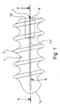
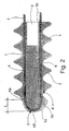
- Figs. 1 and 2 show an embodiment of the suture anchor, wherein the suture channel K is formed entirely inside the anchor body 1, wherein the longitudinal guides 3, 4 are holes that are open at the base 1b of the anchor body 1, directed towards the top 1a of the anchor body, and situated substantially in alignment, preferably on the opposite sides of the longitudinal central line of the anchor body 1, adjacent to the outer surface of the anchor body 1, at the base parts of the screw thread 2.
- a curved, preferably circular hole forming the turning portion 5 and placed entirely inside the anchor body 1 is situated successive to the longitudinal guides 3, 4 combining their head 1 a ends at the junctions 5a, 5b.
- Figs. 3 and 4 show a suture anchor having longitudinal guides 3, 4 of the suture channel K which consist of two grooves made in the outer surface of the anchor body 1, said grooves being situated preferably at the opposite sides of the anchor body 1 and extending from the base 1b of the anchor body to the ends of the curved, preferably circular hole situated inside the anchor body 1 and forming the turning portion 5, wherein the junctions 5a, 5b that are situated on the outer surface of the anchor body 1 are constituted.
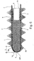
- Figs. 5 and 6 illustrate an embodiment where both the longitudinal guides 3, 4 of the suture channel K and the turning portion 5 have a groove form and are situated on the surface of the anchor body 1, wherein the turning portion 5 is formed at the head 1a of the anchor body 1, on the outer surface thereof, to pass the head 1a in curved, preferably circular groove form, wherein the longitudinal guides 3, 4 connected to the ends of the groove-formed turning portion 5 at the junctions 5a, 5b are placed on the opposite sides of the anchor body 1, substantially parallel with the longitudinal direction of the anchor body 1, to extend to the base 1b of the anchor body.
- the turning portion 5 of the suture channel K constitutes a groove at the head 1a of the anchor body 1, in a respective manner as in the embodiment of Fig. 3 , but the longitudinal guides 3, 4 are formed inside the anchor body 1 (cf. Fig. 1 ) in a manner that they constitute holes which penetrate the anchor body 1 in its longitudinal direction and extend from the base 1 b to the ends of the turning portion 5, up to the junctions 5a, 5b.
- the longitudinal guides 3, 4 can easily be placed in the base 1 b area so that the connecting means 6 can be formed between the longitudinal guides 3, 4 and the connecting means 6 can be used without causing any risk of damaging the suture 7 itself, e.g. when the suture anchor is seated into the bone.
- suture anchors ( Fig. 9 a to d) of various types, in particular with regard to the form of the turning portion 5, were manufactured, wherein
- the aim of the test was to demonstrate how the form of the head of the suture anchor affects the suture Dexon® (USP 1) placed in the suture anchor.
- the suture anchors were attached to first jaws of a device for measuring tensile strength, and the free ends of the suture were attached to second jaws of the device, whereafter the suture was subjected to an effective force, said effective force stretching the suture for breaking it off.
- an effective force said effective force stretching the suture for breaking it off.
- the turning portion form b which, in accordance with the invention, is the most advantageous form for the turning point in the suture anchor, gives the best results in view of the tensile strength.
- the options c and d improve the tensile strength substantially compared to the option a.
Landscapes
- Health & Medical Sciences (AREA)
- Surgery (AREA)
- Life Sciences & Earth Sciences (AREA)
- Medical Informatics (AREA)
- Nuclear Medicine, Radiotherapy & Molecular Imaging (AREA)
- Engineering & Computer Science (AREA)
- Biomedical Technology (AREA)
- Heart & Thoracic Surgery (AREA)
- Rheumatology (AREA)
- Molecular Biology (AREA)
- Animal Behavior & Ethology (AREA)
- General Health & Medical Sciences (AREA)
- Public Health (AREA)
- Veterinary Medicine (AREA)
- Surgical Instruments (AREA)
- Materials For Medical Uses (AREA)
Description
- The present invention relates to a suture anchor in accordance with the preamble of the accompanying
Claim 1. - Suture anchors are used in surgery, in particular in orthopedic surgical operations for placing a part of the suture in and attaching it to a bone, wherein the part of the suture that is not attached, most commonly two parts projecting from the bone, can be further used e.g. for connecting detached connective tissue, such as ligament, to the bone. To place the suture anchor into a bone, a hole is made in the bone, e.g. by drill-ing, into which hole the suture anchor and a part of the suture is inserted, wherein the object of the suture anchor is to keep the suture firmly in the bone, in particular during and after the orthopedic operation.
- In respect of the prevailing level of technology in the field, reference is made mainly to the following patents:
US-5,156,616 ,US-5,472,452 ,US-5,037,422 andWO 96/28100 - In accordance with the suture anchor of patent
US-5,156,616 , two separate sutures are inserted through a hole penetrating the body of the suture anchor in the longitudinal direction and situated substantially in the middle of the cross-section of the anchor body in a manner that the other ends of the sutures extend clearly outside the end at the base side of the suture anchor and the ends at the head side of the suture anchor are tied together, wherein the knot formed thereby prevents the suture from gliding through the hole, out from the suture anchor via its base. The suture anchor is provided with screw threads. - The suture anchor in accordance with patent
US-5,472,452 comprises a tubular body having a substantially quadrangular cross-sectional form, and a core part to be inserted therein. Two walls of the anchor body are provided with projecting branches which are pressed by the core part against the walls of a hole formed in the bone when the suture anchor is pressed into the hole. The branches are further provided with means which can be grabbed by a special tool, e.g. for moving the suture anchor inside the hole. The suture is arranged to circle outside the anchor body via two of its opposite vertical walls and heads. For implementation of this, the heads of said two vertical walls are provided with cuttings in which the suture is placed at the head of the anchor body. - The suture anchor of patent
US-5,037,422 is composed of a conical, hollow body which is positioned by pressing or hitting in a hole made in the bone. For keeping the anchor body in its place, it is provided with two splits situated substantially at the opposite walls thereof and having a cross-section parallel with the suture anchor, wherein the anchor body is contracted when inserted in the hole, tending to expand by pressing the gearing that is formed on the outer surface of the anchor body against the walls of the hole. The suture is positioned to travel substantially through the splits, parallel with them, and arranged to circle via a substantially straight, tubular turning portion situated in the vicinity of the head of the anchor body. - The suture anchor in accordance with the prior-mentioned patent
US-5,156,616 has a simple structure and comprises a screw-thread arrangement which is advantageous when placed in a bone. However, it is unsafe to keep the sutures tied in the suture anchor merely supported by said knot, and it is not possible to fully prevent the sutures from being damaged, in particular at the junction of the knot and the hole penetrating the suture anchor. Furthermore, a device installed in the base of the suture anchor for threading the suture anchor into the bone can damage the sutures, which are situated partially in a sleeve formed for the head of said device in the base of the anchor body. - The drawbacks of the two other solutions mentioned above (
US-5,472,452 andUS-5,037,422 ) are mainly related to the complexity in their structure and use. A particular drawback is that the suture channels through which the sutures are intended to be placed in the suture anchor are formed in a manner that harmfully abrupt alterations of direction take place, in particular adjacent to the heads of the suture anchors (an abrupt alteration of direction of about 90°) which easily results in partial breaking or even cutting off of the suture when the suture is tightened in a later phase of the orthopedic surgical procedure, because the suture is subjected to a strong tensile stress on its outermost surface. - The object of the invention is to introduce a suture anchor whereby the above-described shortcomings pertaining to known suture anchors can be eliminated to a great extent and thus the prevailing level of technology in the field can be elevated.
- For achieving this object, the suture anchor according to the invention is characterized by a novel arrangement between the body of the suture anchor and the suture. This novel arrangement prevents the formation of abrupt alterations of course which add to the risk of damaging the suture. The body of the suture anchor consists of a single part, and the suture channel in which the suture is placed is entirely formed in the anchor body without any separate means and is composed of two longitudinal guides and a particularly curved turning portion which connects them. By means of this arrangement, in particular in view of the turning portion, the tensile strength of the suture required in the surgical operation can be maximally utilized. The primary characteristics of the suture anchor of the invention will be presented in the characterizing portion of the appended
Claim 1. - The simple, substantially closed structure of the anchor body markedly adds to the strength of the suture anchor and thus also increases its operational reliability. The arrangements related to the suture channel also efficiently prevent the risk of damaging, which is present when bringing the suture anchor in the bone and which is particularly caused when the suture gets in contact with the surface of the bone of the drill canal.
- The above-mentioned features and other features characteristic to the present invention, as well as embodiments of the invention will be presented in the accompanying dependent Claims.
- The invention will be illustrated in more detail in the following specification, with reference made to the accompanying drawings. In the drawings,
- Figs. 1 to 8
- show various embodiments of the suture anchor as seen from the side (
Figs. 1 ,3 ,5 and7 ) and corresponding cross-sections in the direction of the longitudinal axis at the location of the suture channel (Figs. 2 ,4 ,6 and8 ), and - Figs. 9a to d
- show heads of various suture anchors used in the test arrangement illustrated as an example.
- The suture anchor of the present invention comprises a substantially closed and
elongated body 1 which is preferably manufactured of a single piece and has preferably a circular cross-section. The longitudinal outer surface of theanchor body 1 is advantageously provided with a set of projections, advantageously ascrew thread 2 having the same size as the longitudinal side of theanchor body 1, for placing the suture anchor, in particular by threading, in a hole formed in the bone. The set of projections can optionally have e.g. a scale-like structure. In this respect reference is made to the structure described in patentFI-95537 - The
anchor body 1 is preferably manufactured of some bioabsorbable material, wherein it is usually not necessary to remove it from the bone, but is it obvious that the possible removal and/or precise moving of a suture anchor provided with ascrew thread 2 can be carried out in the drill canal or hole formed in the bone in a fairly easy manner. It is self-evident that thescrew thread 2 does not require the suture anchor to be positioned in the bone by threading; instead it is possible to insert it into the hole e.g. simply by pressing or hitting. - The head of the
anchor body 1a is preferably formed in a manner that it tapers at least to some extent towards the peak of the head. It is also advantageous that the head of theanchor body 1 is rounded. In thebase 1 b of the anchor body, connectingmeans 6 are formed for connecting an external device with the anchor body for placing the suture anchor in the bone, wherein the connecting means can comprise e.g. a sleeve wrench or the like for the blade part. - The suture channel K for binding the
suture 7 to the suture anchor is entirely formed in theanchor body 1 by using grooves, tubular holes and/or combinations thereof in order to constitute substantially U-formed arrangements. Thus, for example owing to details pertaining to manufacturing techniques and/or bringing the suture anchor in operatable condition, the suture channel K can be formed in accordance with the embodiments shown in the drawings. - The suture channel K comprises two
longitudinal guides turning portion 5 connecting them at their ends of thehead 1 a side of the suture anchor. Thelongitudinal guides anchor body 1 substantially in accordance with the longitudinal direction thereof and, also, substantially on the opposite directions of the longitudinal central line of theanchor body 1. The turningportion 5 is situated at the end of thehead 1a side of thelongitudinal guides turning portion 5 is preferably a continuous curved form, e.g. a circle form, wherein in the area of the suture channel K, no abrupt, sharp angles or the like are formed in thesuture 7 placed in the suture channel K, at which the risk of damaging the suture would be particularly notable in situations in which the suture is subjected to a power influence, said power influence tightening the suture especially during or after a surgical operation. The effect of the form of theturning point 5 on tensile strength is illustrated at the end of the specification by means of an example describing one experimental arrangement. - Since the duration of the tensile stress on the suture can be influenced expressly by the design of the
turning portion 5, in particular with the grade of curvature, it is substantial that theturning portion 5 is formed in a manner that the bending radius of thesuture 7 placed therein does not cause substantial tensile stress on the outermost surface of thesuture 7 when the suture is subjected to an effective force parallel with thelongitudinal guides base 1b of theanchor body 1 in connection with a surgical operation. To implement this object, all the embodiments that will be described in the following share the common feature that theturning portion 5 extends in the longitudinal alignment of the suture anchor, wherein a turning point KP at the top of theturning portion 5 is located at a distance L from thejunctions longitudinal guides turning portion 5. This results in the fact that every alteration angle at theturning portion 5 is smaller than 90° or, in particular (as in the advantageous embodiments shown in the Figures) that the alteration angle of theturning portion 5 is continuous and theturning portion 5 has a curved configuration. -
Figs. 1 and2 show an embodiment of the suture anchor, wherein the suture channel K is formed entirely inside theanchor body 1, wherein thelongitudinal guides base 1b of theanchor body 1, directed towards thetop 1a of the anchor body, and situated substantially in alignment, preferably on the opposite sides of the longitudinal central line of theanchor body 1, adjacent to the outer surface of theanchor body 1, at the base parts of thescrew thread 2. A curved, preferably circular hole forming the turningportion 5 and placed entirely inside theanchor body 1 is situated successive to thelongitudinal guides head 1 a ends at thejunctions -
Figs. 3 and4 show a suture anchor havinglongitudinal guides anchor body 1, said grooves being situated preferably at the opposite sides of theanchor body 1 and extending from thebase 1b of the anchor body to the ends of the curved, preferably circular hole situated inside theanchor body 1 and forming theturning portion 5, wherein thejunctions anchor body 1 are constituted. -
Figs. 5 and6 illustrate an embodiment where both thelongitudinal guides turning portion 5 have a groove form and are situated on the surface of theanchor body 1, wherein theturning portion 5 is formed at thehead 1a of theanchor body 1, on the outer surface thereof, to pass thehead 1a in curved, preferably circular groove form, wherein thelongitudinal guides portion 5 at thejunctions anchor body 1, substantially parallel with the longitudinal direction of theanchor body 1, to extend to thebase 1b of the anchor body. - As shown in
Figs. 7 and8 , the turningportion 5 of the suture channel K constitutes a groove at thehead 1a of theanchor body 1, in a respective manner as in the embodiment ofFig. 3 , but thelongitudinal guides Fig. 1 ) in a manner that they constitute holes which penetrate theanchor body 1 in its longitudinal direction and extend from thebase 1 b to the ends of the turningportion 5, up to thejunctions - It is obvious that the
longitudinal guides base 1 b area so that the connectingmeans 6 can be formed between thelongitudinal guides means 6 can be used without causing any risk of damaging thesuture 7 itself, e.g. when the suture anchor is seated into the bone. - The functionality of the invention is illustrated in the following example.
- Four suture anchors (
Fig. 9 a to d) of various types, in particular with regard to the form of theturning portion 5, were manufactured, wherein - the head form a is a so-called blunt head, wherein the suture has to circle the head substantially via two abrupt angles of about 90° (cf.
US-5,472,452 ), - the head form b is one advantageous head form in accordance with the invention, this head form being a curved, preferably a circled form,
- the head form c is included within the scope of the inventive idea, being a pointed form, in which the suture has to circle via three alterations of course (angles e.g. 60°), and
- the head form d comprises more than three angles, e.g. five angles of 36°.
- The aim of the test was to demonstrate how the form of the head of the suture anchor affects the suture Dexon® (USP 1) placed in the suture anchor. The suture anchors were attached to first jaws of a device for measuring tensile strength, and the free ends of the suture were attached to second jaws of the device, whereafter the suture was subjected to an effective force, said effective force stretching the suture for breaking it off. In the test, the following minimum effective forces were obtained for breaking off the suture:
- a) 87 to 96 N
- b) 186 to 210 N
- c) 153 to 161 N
- d) 154 to 187 N
- The results indicate that the turning portion form b, which, in accordance with the invention, is the most advantageous form for the turning point in the suture anchor, gives the best results in view of the tensile strength. The options c and d improve the tensile strength substantially compared to the option a.
- The invention is neither limited solely to what is described above nor to the embodiments illustrated in the Figures, but it can be modified within the scope of the inventive idea presented in the accompanying Claims.
Claims (11)
- A one-piece suture anchor for anchoring a suture (7) into a bone, wherein a hole for the suture anchor is formed in the bone, the suture anchor comprising an elongated anchor body (1) having a head (1a) and a base (1b), said body (1) provided with a suture channel (K) composed of two elongated longitudinal guides (3, 4) substantially aligned with the longitudinal direction of the anchor body (1) and a turning portion (5) combining the longitudinal guides at the anchor body head (1a) side, characterized in that the turning portion (5) is formed substantially in a manner that it is aligned with the longitudinal dimension of the suture anchor, wherein the turning point at the head of the turning portion (5) is situated at a longitudinal distance from the junctions (5a, 5b) of the longitudinal guides (3, 4) and the turning portion (5), wherein the longitudinal guides and the turning portion have a groove form and are situated on the outer surface of the suture anchor, or the longitudinal guides are channels formed inside the anchor body.
- A suture anchor as set forth in Claim 1, characterized in that the alteration angle of the turning portion (5) between the junctions (5a, 5b) is continuous and that the turning portion (5) has a curved configuration.
- A suture anchor as set forth in Claim 1, characterized in that each alteration angle of the turning portion (5) between the junctions (5a, 5b) is smaller than 90°.
- A suture anchor as set forth in any of the preceding Claims, characterized in that the longitudinal guides (3, 4) consist of two holes which are open at the base (1b) of the anchor body and are positioned inside the anchor body (1), said holes being connected together at their ends of the anchor body head (1a) side that remain inside the anchor body (1) by means of a tubular turning portion (5) that is situated inside the anchor body (1).
- A suture anchor as set forth in any of Claims 1 to 3, characterized in that the longitudinal guides (3, 4) consist of two grooves formed on the surface of the anchor body (1) and extending parallel with the longitudinal direction of the anchor body (1) from the base (1b) to the head (1a) of the anchor body, substantially to the opposite sides of the anchor body (1), wherein the turning portion (5) is composed of the groove formed on the surface of the head (1a) of the anchor body and connecting the longitudinal guides (3, 4).
- A suture anchor as set forth in any of Claims 1 to 3, characterized in that the longitudinal guides (3, 4) consist of two holes longitudinally parallel with the anchor body (1) and penetrating the anchor body, wherein the turning portion (5) is composed of a groove formed on the surface of the head (1a) of the anchor body and connecting the longitudinal guides (3, 4).
- A suture anchor as set forth in any of the preceding Claims, characterized in that the outer surface of the anchor body (1) is provided with a set of projections, advantageously a screw thread (2), which is substantially of the same length as the longitudinal side of the anchor body (1).
- A suture anchor as set forth in any of the preceding Claims, characterized in that the anchor body (1) is provided with connecting means (6) formed at the base (1b) thereof for connecting the suture anchor to an external device for seating the suture anchor into the bone.
- A suture anchor as set forth in Claims 7 and 8, characterized in that the connecting means (6) comprise a sleeve or the like for connecting the suture anchor to a wrench or the like.
- A suture anchor as set forth in any of the preceding Claims, characterized in that the anchor body (1) is manufactured of biodegradable material.
- A suture anchor as set forth in any of the preceding Claims, characterized in that the suture does not extend past the head (la) of the anchor body.
Applications Claiming Priority (3)
| Application Number | Priority Date | Filing Date | Title |
|---|---|---|---|
| FI965111A FI111802B (en) | 1996-12-19 | 1996-12-19 | Suture anchors |
| FI965111 | 1996-12-19 | ||
| PCT/US1997/022428 WO1998026717A1 (en) | 1996-12-19 | 1997-12-03 | Suture anchor |
Publications (3)
| Publication Number | Publication Date |
|---|---|
| EP0967921A1 EP0967921A1 (en) | 2000-01-05 |
| EP0967921A4 EP0967921A4 (en) | 2009-06-03 |
| EP0967921B1 true EP0967921B1 (en) | 2013-05-15 |
Family
ID=8547315
Family Applications (1)
| Application Number | Title | Priority Date | Filing Date |
|---|---|---|---|
| EP97950876.9A Expired - Lifetime EP0967921B1 (en) | 1996-12-19 | 1997-12-03 | Suture anchor |
Country Status (6)
| Country | Link |
|---|---|
| EP (1) | EP0967921B1 (en) |
| JP (1) | JP2001506155A (en) |
| AU (1) | AU5376698A (en) |
| CA (1) | CA2275682A1 (en) |
| FI (1) | FI111802B (en) |
| WO (1) | WO1998026717A1 (en) |
Families Citing this family (17)
| Publication number | Priority date | Publication date | Assignee | Title |
|---|---|---|---|---|
| US5957924A (en) * | 1997-05-22 | 1999-09-28 | Bionx Implants Oy | Installation tool for suture anchor |
| US6406498B1 (en) | 1998-09-04 | 2002-06-18 | Bionx Implants Oy | Bioactive, bioabsorbable surgical composite material |
| US9521999B2 (en) | 2005-09-13 | 2016-12-20 | Arthrex, Inc. | Fully-threaded bioabsorbable suture anchor |
| US8343186B2 (en) | 2004-04-06 | 2013-01-01 | Arthrex, Inc. | Fully threaded suture anchor with transverse anchor pin |
| AU2003215582A1 (en) * | 2002-02-22 | 2003-09-09 | Degima Medizinprodukte Gmbh | Soft tissue suture anchor |
| DE102005039080A1 (en) * | 2005-08-05 | 2007-02-08 | Karl Storz Gmbh & Co. Kg | Anchor element for fixing a tendon |
| ATE498360T1 (en) | 2005-09-12 | 2011-03-15 | Arthrex Inc | EYELET SEAM ANCHOR |
| US8894661B2 (en) | 2007-08-16 | 2014-11-25 | Smith & Nephew, Inc. | Helicoil interference fixation system for attaching a graft ligament to a bone |
| US8083769B2 (en) * | 2006-11-01 | 2011-12-27 | Depuy Mitek, Inc. | Wired sutures |
| US9579188B2 (en) | 2010-03-10 | 2017-02-28 | Smith & Nephew, Inc. | Anchor having a controlled driver orientation |
| US9775702B2 (en) | 2010-03-10 | 2017-10-03 | Smith & Nephew, Inc. | Composite interference screws and drivers |
| EP2544625B1 (en) | 2010-03-10 | 2020-09-23 | Smith & Nephew, Inc. | Composite interference screws and drivers |
| US9308080B2 (en) | 2010-03-10 | 2016-04-12 | Smith & Nephew Inc. | Composite interference screws and drivers |
| WO2012125578A2 (en) | 2011-03-11 | 2012-09-20 | Smith & Nephew, Inc. | Trephine |
| RU2604036C2 (en) | 2011-06-07 | 2016-12-10 | Смит Энд Нефью, Инк. | Surgical instrument |
| US9155531B2 (en) | 2013-03-15 | 2015-10-13 | Smith & Nephew, Inc. | Miniaturized dual drive open architecture suture anchor |
| WO2014169058A1 (en) | 2013-04-09 | 2014-10-16 | Smith & Nephew, Inc | Open-architecture interference screw |
Family Cites Families (9)
| Publication number | Priority date | Publication date | Assignee | Title |
|---|---|---|---|---|
| US5037422A (en) | 1990-07-02 | 1991-08-06 | Acufex Microsurgical, Inc. | Bone anchor and method of anchoring a suture to a bone |
| US5258016A (en) * | 1990-07-13 | 1993-11-02 | American Cyanamid Company | Suture anchor and driver assembly |
| US5156616A (en) | 1992-02-10 | 1992-10-20 | Meadows Bruce F | Apparatus and method for suture attachment |
| US5423860A (en) * | 1993-05-28 | 1995-06-13 | American Cyanamid Company | Protective carrier for suture anchor |
| US5324308A (en) * | 1993-10-28 | 1994-06-28 | Javin Pierce | Suture anchor |
| US5584695A (en) * | 1994-03-07 | 1996-12-17 | Memory Medical Systems, Inc. | Bone anchoring apparatus and method |
| US5472452A (en) | 1994-08-30 | 1995-12-05 | Linvatec Corporation | Rectilinear anchor for soft tissue fixation |
| US5464427A (en) * | 1994-10-04 | 1995-11-07 | Synthes (U.S.A.) | Expanding suture anchor |
| US5643320A (en) * | 1995-03-13 | 1997-07-01 | Depuy Inc. | Soft tissue anchor and method |
-
1996
- 1996-12-19 FI FI965111A patent/FI111802B/en not_active IP Right Cessation
-
1997
- 1997-12-03 CA CA002275682A patent/CA2275682A1/en not_active Abandoned
- 1997-12-03 WO PCT/US1997/022428 patent/WO1998026717A1/en not_active Ceased
- 1997-12-03 EP EP97950876.9A patent/EP0967921B1/en not_active Expired - Lifetime
- 1997-12-03 JP JP52777898A patent/JP2001506155A/en active Pending
- 1997-12-03 AU AU53766/98A patent/AU5376698A/en not_active Abandoned
Also Published As
| Publication number | Publication date |
|---|---|
| WO1998026717A1 (en) | 1998-06-25 |
| FI111802B (en) | 2003-09-30 |
| EP0967921A4 (en) | 2009-06-03 |
| AU5376698A (en) | 1998-07-15 |
| JP2001506155A (en) | 2001-05-15 |
| EP0967921A1 (en) | 2000-01-05 |
| FI965111A0 (en) | 1996-12-19 |
| FI965111L (en) | 1998-07-03 |
| CA2275682A1 (en) | 1998-06-25 |
Similar Documents
| Publication | Publication Date | Title |
|---|---|---|
| US6436124B1 (en) | Suture anchor | |
| AU5376698A (en) | Suture anchor | |
| US6149669A (en) | Surgical fastener assembly method of use | |
| US7442202B2 (en) | Suture anchor attached to tissue-fixation disk without top knot | |
| EP2316379B1 (en) | Partial thickness rotator cuff repair system | |
| US20200178955A1 (en) | System and method for attaching soft tissue to bone | |
| US7144415B2 (en) | Anchor/suture used for medical procedures | |
| EP1202672B1 (en) | Self-locking suture anchor | |
| US9402618B2 (en) | Suture anchors and assemblies for attaching soft tissue to bone | |
| US20070032792A1 (en) | Surgical suture anchor element | |
| US20040088004A1 (en) | Suture anchor | |
| AU2013231063B2 (en) | System and method for attaching soft tissue to bone |
Legal Events
| Date | Code | Title | Description |
|---|---|---|---|
| PUAI | Public reference made under article 153(3) epc to a published international application that has entered the european phase |
Free format text: ORIGINAL CODE: 0009012 |
|
| 17P | Request for examination filed |
Effective date: 19990719 |
|
| AK | Designated contracting states |
Kind code of ref document: A1 Designated state(s): AT BE CH DE DK ES FI FR GB GR IE IT LI LU MC NL PT SE |
|
| RAP1 | Party data changed (applicant data changed or rights of an application transferred) |
Owner name: LINVATEC BIOMATERIALS OY |
|
| A4 | Supplementary search report drawn up and despatched |
Effective date: 20090508 |
|
| 17Q | First examination report despatched |
Effective date: 20091029 |
|
| GRAP | Despatch of communication of intention to grant a patent |
Free format text: ORIGINAL CODE: EPIDOSNIGR1 |
|
| GRAS | Grant fee paid |
Free format text: ORIGINAL CODE: EPIDOSNIGR3 |
|
| GRAP | Despatch of communication of intention to grant a patent |
Free format text: ORIGINAL CODE: EPIDOSNIGR1 |
|
| GRAA | (expected) grant |
Free format text: ORIGINAL CODE: 0009210 |
|
| AK | Designated contracting states |
Kind code of ref document: B1 Designated state(s): AT BE CH DE DK ES FI FR GB GR IE IT LI LU MC NL PT SE |
|
| REG | Reference to a national code |
Ref country code: GB Ref legal event code: FG4D Ref country code: CH Ref legal event code: EP |
|
| REG | Reference to a national code |
Ref country code: AT Ref legal event code: REF Ref document number: 611712 Country of ref document: AT Kind code of ref document: T Effective date: 20130615 |
|
| REG | Reference to a national code |
Ref country code: IE Ref legal event code: FG4D |
|
| REG | Reference to a national code |
Ref country code: DE Ref legal event code: R096 Ref document number: 69740598 Country of ref document: DE Effective date: 20130711 |
|
| REG | Reference to a national code |
Ref country code: AT Ref legal event code: MK05 Ref document number: 611712 Country of ref document: AT Kind code of ref document: T Effective date: 20130515 |
|
| REG | Reference to a national code |
Ref country code: NL Ref legal event code: VDEP Effective date: 20130515 |
|
| PG25 | Lapsed in a contracting state [announced via postgrant information from national office to epo] |
Ref country code: SE Free format text: LAPSE BECAUSE OF FAILURE TO SUBMIT A TRANSLATION OF THE DESCRIPTION OR TO PAY THE FEE WITHIN THE PRESCRIBED TIME-LIMIT Effective date: 20130515 Ref country code: PT Free format text: LAPSE BECAUSE OF FAILURE TO SUBMIT A TRANSLATION OF THE DESCRIPTION OR TO PAY THE FEE WITHIN THE PRESCRIBED TIME-LIMIT Effective date: 20130916 Ref country code: AT Free format text: LAPSE BECAUSE OF FAILURE TO SUBMIT A TRANSLATION OF THE DESCRIPTION OR TO PAY THE FEE WITHIN THE PRESCRIBED TIME-LIMIT Effective date: 20130515 Ref country code: GR Free format text: LAPSE BECAUSE OF FAILURE TO SUBMIT A TRANSLATION OF THE DESCRIPTION OR TO PAY THE FEE WITHIN THE PRESCRIBED TIME-LIMIT Effective date: 20130816 Ref country code: ES Free format text: LAPSE BECAUSE OF FAILURE TO SUBMIT A TRANSLATION OF THE DESCRIPTION OR TO PAY THE FEE WITHIN THE PRESCRIBED TIME-LIMIT Effective date: 20130826 Ref country code: FI Free format text: LAPSE BECAUSE OF FAILURE TO SUBMIT A TRANSLATION OF THE DESCRIPTION OR TO PAY THE FEE WITHIN THE PRESCRIBED TIME-LIMIT Effective date: 20130515 |
|
| PG25 | Lapsed in a contracting state [announced via postgrant information from national office to epo] |
Ref country code: DK Free format text: LAPSE BECAUSE OF FAILURE TO SUBMIT A TRANSLATION OF THE DESCRIPTION OR TO PAY THE FEE WITHIN THE PRESCRIBED TIME-LIMIT Effective date: 20130515 Ref country code: BE Free format text: LAPSE BECAUSE OF FAILURE TO SUBMIT A TRANSLATION OF THE DESCRIPTION OR TO PAY THE FEE WITHIN THE PRESCRIBED TIME-LIMIT Effective date: 20130515 |
|
| PG25 | Lapsed in a contracting state [announced via postgrant information from national office to epo] |
Ref country code: NL Free format text: LAPSE BECAUSE OF FAILURE TO SUBMIT A TRANSLATION OF THE DESCRIPTION OR TO PAY THE FEE WITHIN THE PRESCRIBED TIME-LIMIT Effective date: 20130515 Ref country code: IT Free format text: LAPSE BECAUSE OF FAILURE TO SUBMIT A TRANSLATION OF THE DESCRIPTION OR TO PAY THE FEE WITHIN THE PRESCRIBED TIME-LIMIT Effective date: 20130515 |
|
| PLBE | No opposition filed within time limit |
Free format text: ORIGINAL CODE: 0009261 |
|
| STAA | Information on the status of an ep patent application or granted ep patent |
Free format text: STATUS: NO OPPOSITION FILED WITHIN TIME LIMIT |
|
| 26N | No opposition filed |
Effective date: 20140218 |
|
| REG | Reference to a national code |
Ref country code: DE Ref legal event code: R097 Ref document number: 69740598 Country of ref document: DE Effective date: 20140218 |
|
| REG | Reference to a national code |
Ref country code: CH Ref legal event code: PL |
|
| PG25 | Lapsed in a contracting state [announced via postgrant information from national office to epo] |
Ref country code: LU Free format text: LAPSE BECAUSE OF FAILURE TO SUBMIT A TRANSLATION OF THE DESCRIPTION OR TO PAY THE FEE WITHIN THE PRESCRIBED TIME-LIMIT Effective date: 20131203 Ref country code: MC Free format text: LAPSE BECAUSE OF FAILURE TO SUBMIT A TRANSLATION OF THE DESCRIPTION OR TO PAY THE FEE WITHIN THE PRESCRIBED TIME-LIMIT Effective date: 20130515 |
|
| REG | Reference to a national code |
Ref country code: IE Ref legal event code: MM4A |
|
| PG25 | Lapsed in a contracting state [announced via postgrant information from national office to epo] |
Ref country code: IE Free format text: LAPSE BECAUSE OF NON-PAYMENT OF DUE FEES Effective date: 20131203 Ref country code: CH Free format text: LAPSE BECAUSE OF NON-PAYMENT OF DUE FEES Effective date: 20131231 Ref country code: LI Free format text: LAPSE BECAUSE OF NON-PAYMENT OF DUE FEES Effective date: 20131231 |
|
| REG | Reference to a national code |
Ref country code: FR Ref legal event code: PLFP Year of fee payment: 19 |
|
| REG | Reference to a national code |
Ref country code: FR Ref legal event code: PLFP Year of fee payment: 20 |
|
| PGFP | Annual fee paid to national office [announced via postgrant information from national office to epo] |
Ref country code: GB Payment date: 20161228 Year of fee payment: 20 |
|
| PGFP | Annual fee paid to national office [announced via postgrant information from national office to epo] |
Ref country code: FR Payment date: 20161227 Year of fee payment: 20 |
|
| PGFP | Annual fee paid to national office [announced via postgrant information from national office to epo] |
Ref country code: DE Payment date: 20161229 Year of fee payment: 20 |
|
| REG | Reference to a national code |
Ref country code: DE Ref legal event code: R071 Ref document number: 69740598 Country of ref document: DE |
|
| REG | Reference to a national code |
Ref country code: GB Ref legal event code: PE20 Expiry date: 20171202 |
|
| PG25 | Lapsed in a contracting state [announced via postgrant information from national office to epo] |
Ref country code: GB Free format text: LAPSE BECAUSE OF EXPIRATION OF PROTECTION Effective date: 20171202 |