EP0967702A2 - Cable retainer of plastics for vehicles - Google Patents
Cable retainer of plastics for vehicles Download PDFInfo
- Publication number
- EP0967702A2 EP0967702A2 EP99110741A EP99110741A EP0967702A2 EP 0967702 A2 EP0967702 A2 EP 0967702A2 EP 99110741 A EP99110741 A EP 99110741A EP 99110741 A EP99110741 A EP 99110741A EP 0967702 A2 EP0967702 A2 EP 0967702A2
- Authority
- EP
- European Patent Office
- Prior art keywords
- shank
- cable retainer
- retaining portion
- cable
- engagement
- Prior art date
- Legal status (The legal status is an assumption and is not a legal conclusion. Google has not performed a legal analysis and makes no representation as to the accuracy of the status listed.)
- Granted
Links
Images
Classifications
-
- H—ELECTRICITY
- H02—GENERATION; CONVERSION OR DISTRIBUTION OF ELECTRIC POWER
- H02G—INSTALLATION OF ELECTRIC CABLES OR LINES, OR OF COMBINED OPTICAL AND ELECTRIC CABLES OR LINES
- H02G3/00—Installations of electric cables or lines or protective tubing therefor in or on buildings, equivalent structures or vehicles
- H02G3/26—Installations of cables, lines, or separate protective tubing therefor directly on or in walls, ceilings, or floors
-
- B—PERFORMING OPERATIONS; TRANSPORTING
- B60—VEHICLES IN GENERAL
- B60R—VEHICLES, VEHICLE FITTINGS, OR VEHICLE PARTS, NOT OTHERWISE PROVIDED FOR
- B60R16/00—Electric or fluid circuits specially adapted for vehicles and not otherwise provided for; Arrangement of elements of electric or fluid circuits specially adapted for vehicles and not otherwise provided for
- B60R16/02—Electric or fluid circuits specially adapted for vehicles and not otherwise provided for; Arrangement of elements of electric or fluid circuits specially adapted for vehicles and not otherwise provided for electric constitutive elements
- B60R16/0207—Wire harnesses
- B60R16/0215—Protecting, fastening and routing means therefor
Definitions
- the invention relates to a cable retainer of plastics for vehicles.
- the cables, cable bundles or cable looms must be fastened to the associated car body parts in a suitable manner.
- the fastening must be of a manner such than they cause the minimal of assembly effort.
- the means applied for this must be able to be manufactured with a low expense.
- the fastening is of a manner such that the cables or cable bundles are securely attached and are not loosened by vibration, wherein a formation of noise in any case is to be avoided.
- the attachment of the cables is also to be in a manner such that they do not suffer any damage over a long operation.
- the cable bundles consist usually of a toothed strip which may be inserted into a lock arranged at the other end of the strip, by which means on account of the toothing it may be locked in stepped portions. It is also known to connect such cable strips with an expanding rivet or with another fastening element, in order to fasten the cable to the allocated car body part. For this purpose the expanding rivet or a similar fastening part is lockingly inserted into a hole mounted at the predetermined location.
- Cable retainers are known which provide a similar fastening possibility to the car body and which comprise a cuff-like portion for enclosing one or more cables.
- studs Alternatively to a fastening hole in the car body of a vehicle it is also known to attach so-called studs.
- the studs comprise a thread-like or annular groove.
- Fastening elements of plastic are inserted onto the studs in a sleeve-like manner, wherein an engagement with the groove of the stud is effected in order to attach the fastening element firmly on the car body.
- the cable retainer comprises a hollow shank which on the outer side comprises at least one radially deformable outer engagement portion which grips behind the edge of a hole of the vehicle car body when the shank is inserted into the hole.
- the shank on the inside further comprises at least one radially deformable inner engagement portion which engages into the thread or other groove of a stud of a vehicle car body when the shank is pushed onto the stud.
- the fastening holes in car bodies comprise usually a predetermined diameter. It can therefore be realized without difficulties to select the dimensions of the shank on the inside and outside such that the shank may be incorporated or mounted in predetermined fastening hole as well as on a predetermined stud and here may be securely fastened.
- the shank is at one end connected to an elongate retaining portion extending transversely to this, around which a cable strip may be wrapped.
- a cable strip which has already been described above.
- a tape may also be provided which is laid around the cable or cable bundle with a simultaneous wrapping around of the retaining element.
- the cable retainer according to the invention has the advantage that it is designed for two differing fastening possibilities. This leads to a reduction of the variants of fastening means at the manufacturer of the vehicle.
- the retaining portion at at least one end comprises a projection extending approximately parallel to the shank. Such a projection reduces a slipping of the strip over the free end of the retaining portion and thus a release of the strip from the cable retainer.
- the retaining portion may be plate-shaped or may be formed concavely for forming a channel or a duct for the secured accommodation of the cable or the cable bundle.
- the retaining portion comprises a resiliently yielding biasing portion on the same side as the shank, over which the strip extends, wherein the biasing portion exerts a biasing force on the strip.
- the biasing portion may be formed as a U-shaped portion which is formed as one piece on the lower side of the retaining portion, wherein the strip bears against the web of the U-shaped biasing portion.
- the web may be deformed within limits and be biased by the strip on wrapping around so that the strip is constantly held with biasing. This above all things is important when it is not possible to pull the strip so tightly around the retaining portion that an unmovable fastening of the cable is achieved.
- the web of the U-shaped biasing portion according to a further formation of the invention is arcuate in the direction of the retaining portion. By way of this at the same time a lateral securement is created.
- the shank on oppositely lying sides comprises prong-shaped snapping portions which with their end distant to the retaining portion are connected on the shaft and with their free end facing the retaining portion project somewhat beyond the outer contour of the shank in order to grip behind the edge of the hole.
- the shank comprises near to the connection in each case oppositely lying engagement teeth with a concave engagement edge, which extend radially inwards and when inserting the shank onto the stud deform so far that the teeth may slide over the grooving of the stud until they engage into the grooving at a predetermined location.
- the snapping prongs or snapping fingers comprise at the free end preferably a shoulder which engages with the edge of the hole when the shank is inserted into a hole.
- the engagement tooth on the inner side of the shank extends preferably obliquely upwards into the inside of the shank so that they act in the manner of a hook barb in a manner such that on insertion onto a stud they may be relatively easily deformed, but which opposes the pulling of the shank from the stud with a high resistance.
- Another formation of the invention provides for the shank to comprise on the outside on oppositely lying sides a row of approximately radially flexible snapping prongs, this row extending parallel to the axis of the shank.
- a fastening element is known per se.
- Such a fastening element is for example known as a spiked clip or pine-tree clip. It has the advantage that the engagement depth of the shank in the fastening hole is formed variably over a large range. It has the further advantage that on retraction not only the resistance of one snapping prong, but all snapping prongs which lie above the snapping prong located in engagement is to be overcome.
- engagement teeth On the inside of the shank likewise diametrically oppositely lying engagement teeth may be provided, which are preferably formed flexible in order to yield on pushing on a stud. Preferably in each case an engagement tooth is aligned radially to a row of engagement teeth.
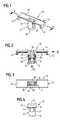
- a cable retainer according to the Figures 1 to 4 comprises a shank 12 and a retaining portion 14.
- the shank is formed cylindrically or sleeve-like with a conical introduction portion 16 at the lower end.
- latching prongs or fingers 18, 20 which at the lower end are connected onto the shank 12, but extend obliquely upwards and outwards. This concerns however the outer contour of the prongs 18, 20 which is correspondingly conical.
- the snapping prongs 18, 20 comprise a shoulder 22 and 24 respectively which grip the edge of a fastening hole which is not shown, when the shank 12 is introduced into the fastening hole.
- the shank 12 In the inside the shank 12 comprises concavely arcuate guiding portions 26, 28 lying opposite, which are adapted to the outer diameter of a stud which is not shown. On oppositely lying sides, rotated about 90° to the guiding portions 26, 28, there are formed two diametrically oppositely lying engagement teeth 30, 32. As is deduced from Fig. 2 the engagement teeth 30, 32 extend inwardly and upwardly, in the manner of a hook barb. They have a circular arc shaped engagement edge 36 at the free end. The distance of the engagement edges 36 is somewhat less than the diameter of the stud so that on pushing on the shank 12 onto the stud, which is not shown, the engagement teeth 30, 32 are swung out upwardly and the engagement edges 36 slide over the grooving of the stud.
- the retaining portion 14 formed of plastic as one piece with the upper end of the shank 12 comprises a groove-like portion 40 extending to both sides of the shank 12, which serves for accommodating a cable or a cable bundle. At the ends it has projections 42, 44 facing downwards.
- a cable strip or a tape which at the same time is also laid around the retaining portion 14. By way of this the cable or the cable bundle is fastened on the retainer 10.
- the projections 42, 44 prevent a lateral sliding off of the attachment.
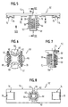
- a cable retainer 50 comprises a shank 52 and a retaining portion 54.
- the shank 52 which is sleeve-shaped or cylindrical in it basic construction and comprises a conical free introduction end 56, is provided with four rows of flexible snapping prongs 58 which extend radially outwards and a little obliquely upwards. There may also be provided only two rows of engagement teeth which here is not shown. The rows of engagement teeth 58 in the circumferential direction are arranged displaced to one another by in each case 90° and run approximately parallel to the axis of the shank 52.
- Such an outer contour of a shank of a fastening element is known per se. It is known under the term spiked or pine-tree clip. With such a formation the shank 52 may be attached in a fastening hole over a variable depth.
- engagement teeth 60 which are arranged in a circumferential distance of 90°, between which there lie reliefs 62 so that the engagement teeth on placing the shank onto a non-shown stud yield and engage into a predetermined groove.
- the concave engagement edge 66 of the engagement teeth 60 is arranged at a distance to the oppositely lying engagement edge 66 which is smaller than the outer diameter of the stud.
- the shank 52 is connected to the retaining portion 54 extending on both sides of the shank 52 transversely thereto via web-like connection portions 68, 70. They serve as a rotational securement on assembly of the retainer in a square hole.
- An opening 80 in the shank below the retaining portion may serve to accommodate a cable strip (not shown) or to strike the cable retainer laterally on a threaded bolt.
- the retaining portion 54 consists essentially of an elongate rectangular plate which on the lower side comprises U-shaped biasing portions 72, 74.
- the biasing portions 72, 74 connected as one piece to the retaining portion 54 at the lower side of the plate at the ends comprise a web 76 which is curved concavely towards the plate.
- the cable strip or tape externally is guided over the web 76 then it is securely held by the curvature.
- the deformation of the web 76 or the arms which occur with a certain tension produces a biasing on the cable strip or the tape. It is however also possible to guide a cable strip or tape through the eyelet which is formed by the biasing portion 72, 74. In this case the web 76 may serve for bearing with tension against the strip or tape in order by way of this to prevent a slipping.
Abstract
- a hollow shank portion adapted to be inserted into a hole of the vehicle body, the shank portion having at least one outer engagement portion which is radially deformable and grips behind the edge of the hole if the shank is inserted into the hole, the shank being adapted to be pushed onto a stud of the vehicle body which has a plurality of grooves or a thread, the shank further having an inner engagement portion which is radially deformable and engages a groove or the thread if the shank is pushed onto the stud,
- a retaining portion connected to one end of the shank portion and extending transverse to the axis of the shank portions and
- a strip encircling a cable and the retaining portion as well.
Description
- Fig. 1
- shows perspectively a first embodiment form of a cable retainer according to the invention.
- Fig. 2
- shows a section through the representation according to Fig. 1, along the line 2-2.
- Fig. 3
- shows a view from below of the cable retainer according to Fig. 2, in the direction of arrow 4.
- Fig. 4
- shows a lateral view of the cable retainer according to Fig. 2 in the direction of arrow 4.
- Fig. 5
- shows a lateral view of a second embodiment form of a cable retainer according to the invention.
- Fig. 6
- shows a section through the cable retainer according to Fig. 5, along the line 6-6.
- Fig. 7
- shows a section through the cable retainer according to Fig. 5, along the line 7-7.
- Fig. 8
- shows a view from below of the cable retainer according to Fig. 5, in the direction of arrow 8.
Claims (13)
- A cable retainer made of plastics and being usable for vehicles having a body, comprisinga hollow shank portion (12, 52) adapted to be inserted into a hole of the vehicle body, the shank portion (12, 52) having at least one outer engagement portion which is radially deformable and grips behind the edge of the hole if the shank is inserted into the hole, the shank (12, 52) being adapted to be pushed onto a stud of the vehicle body which has a plurality of grooves or a thread, the shank further having an inner engagement portion (36, 60) which is radially deformable and engages a groove or the thread if the shank is pushed onto the stud,a retaining portion (14, 54) connected to one end of the shank portion (12, 52) and extending transverse to the axis of the shank portions anda strip encircling a cable and the retaining portion (14, 54) as well.
- The cable retainer of claim 1, wherein the retaining portion (14, 54) extends beyond both sides of the shank (12, 52).
- The cable retainer of claim 1, wherein at least one end of the retaining portion (14) has a projection (42, 44) extending approximately parallel to the shank.
- The cable retainer of claim 1, wherein the retaining portion has a resilient biasing portion on the same side as the shaft, the biasing portion biasing the strip extending over the biasing portion.
- The cable retainer of claim 4, wherein an approximately U-shaped biasing portion (72, 74) is integrally formed by the retaining portion (54), with the strip engaging the web of the U-shaped biasing portion (72, 74).
- The cable retainer of claim 5, wherein the web portion (76) of the biasing portion (72, 74) is arcuately formed towards the retaining portion (54).
- The cable retainer of claim 1, wherein the retaining portion (54) is plate-shaped.
- The cable retainer of claim 1, wherein the retaining portion (72) has a receiving channel for the cable arcuate in cross section.
- The cable retainer of claim 1, wherein the shank (12) has prong-shaped snapping portions (18, 22) on opposite sides which are connected to the shaft (12) with its end opposite to the retaining portion (14), the free ends thereof facing the retaining portion normally extending beyond the outer contour of shank (12), the snapping portions are gripping behind the edge of the hole, and wherein the shaft (12) has a flexible snapping tooth (30, 32) on the inner side adjacent to the connection of the prong portions (18, 20), the snapping tooth (30, 32) having a concave engagement edge (36).
- The cable retainer of claim 9, wherein the snapping tooth (30, 32) extends upwardly towards the retaining portion (14) and has a relatively sharp engagement edge (38).
- The cable retainer of claim 1, wherein on opposite sides of shank (52) rows of radial flexible snapping prongs are provided, the rows extending parallel to the shank axis (Igel).
- The cable retainer of claim 11, wherein the shank (12) has engagement teeth (30, 32) on opposite inner sides, the teeth extending radially inwardly and having a concave engagement edge (66).
- The cable retainer of claim 12, wherein the engagement teeth (30, 32) are radially aligned the rows of prongs (58).
Applications Claiming Priority (2)
| Application Number | Priority Date | Filing Date | Title |
|---|---|---|---|
| DE19828073A DE19828073C1 (en) | 1998-06-24 | 1998-06-24 | Plastic cable holder for vehicles |
| DE19828073 | 1998-06-24 |
Publications (3)
| Publication Number | Publication Date |
|---|---|
| EP0967702A2 true EP0967702A2 (en) | 1999-12-29 |
| EP0967702A3 EP0967702A3 (en) | 2000-02-23 |
| EP0967702B1 EP0967702B1 (en) | 2007-08-15 |
Family
ID=7871832
Family Applications (1)
| Application Number | Title | Priority Date | Filing Date |
|---|---|---|---|
| EP99110741A Expired - Lifetime EP0967702B1 (en) | 1998-06-24 | 1999-06-04 | Cable retainer of plastics for vehicles |
Country Status (4)
| Country | Link |
|---|---|
| US (1) | US6320134B1 (en) |
| EP (1) | EP0967702B1 (en) |
| CA (1) | CA2274276C (en) |
| DE (2) | DE19828073C1 (en) |
Cited By (4)
| Publication number | Priority date | Publication date | Assignee | Title |
|---|---|---|---|---|
| WO2002100686A1 (en) * | 2001-06-06 | 2002-12-19 | Yazaki Corporation | Clamp |
| WO2005036041A1 (en) * | 2003-09-16 | 2005-04-21 | A. Raymond & Cie | Device for fastening at least one elongate object to a base |
| FR2872250A1 (en) * | 2004-06-29 | 2005-12-30 | Valeo Electronique Sys Liaison | CLAMP FOR ATTACHING A WIRING BEAM |
| WO2007051639A1 (en) | 2005-11-03 | 2007-05-10 | Hellermann Tyton Gmbh | Fixing rail for an elongate object |
Families Citing this family (19)
| Publication number | Priority date | Publication date | Assignee | Title |
|---|---|---|---|---|
| US7120971B2 (en) | 2001-03-02 | 2006-10-17 | Newfrey Llc | Low insertion effort u-base retainer |
| DE10160268B4 (en) * | 2001-12-07 | 2004-12-09 | Daimlerchrysler Ag | Bracket for cables and / or wires in a vehicle |
| DE10313411B3 (en) | 2003-03-25 | 2004-08-26 | Newfrey Llc, Newark | Support clamp for pipes and cables has pair of arms forming U- shaped assembly with fastening screw or dowel on bottom and has wedges operated by longitudinally-sliding portion |
| DE10328989B4 (en) | 2003-06-27 | 2018-09-13 | Bayerische Motoren Werke Aktiengesellschaft | Einsteckclip for attachment of wire harnesses o. |
| DE10332376B4 (en) | 2003-07-17 | 2018-03-22 | Volkswagen Ag | Connection between a holding element for holding a cable and / or cable strand and at least one carrier element on a vehicle |
| US7753320B2 (en) * | 2005-07-28 | 2010-07-13 | Hellermanntyton Corporation | Flush mount connector clip |
| JP4566863B2 (en) * | 2005-08-31 | 2010-10-20 | 本田技研工業株式会社 | Cable holding device for vehicle |
| DE202005015875U1 (en) * | 2005-10-07 | 2007-02-15 | S-Fasteners Gmbh | Holder arrangement for cables or similar with adjustable turn-stop positions |
| FR2950490B1 (en) * | 2009-09-23 | 2012-11-16 | Labinal | CABLE PATH FOR AIRCRAFT HAVING COMPOSITE MATERIAL STRUCTURE |
| DE102009056801A1 (en) | 2009-12-03 | 2011-06-09 | A. Raymond Et Cie | fastening device |
| JP5484182B2 (en) * | 2010-04-30 | 2014-05-07 | 株式会社パイオラックス | clip |
| JP5619471B2 (en) * | 2010-05-06 | 2014-11-05 | 矢崎総業株式会社 | Fixture for wire harness |
| JP5673451B2 (en) * | 2011-09-05 | 2015-02-18 | 住友電装株式会社 | Wire harness exterior |
| JP6162437B2 (en) * | 2013-03-07 | 2017-07-12 | 大和化成工業株式会社 | clip |
| DE102015214109A1 (en) | 2015-07-27 | 2017-02-02 | Magna Car Top Systems Gmbh | Attachment with front-side cable routing |
| US9899822B2 (en) * | 2016-01-04 | 2018-02-20 | Nexans | Threaded hole retainer |
| RU172026U1 (en) * | 2017-01-18 | 2017-06-26 | Ооо "Аетек" | Modular comb for attaching electrical wires |
| DE102019134313A1 (en) * | 2019-12-13 | 2021-06-17 | Westfalia-Automotive Gmbh | Fastening device for fastening a line to a trailer coupling |
| US11865981B2 (en) | 2020-05-05 | 2024-01-09 | Thor Tech, Inc. | Wire loom support |
Citations (7)
| Publication number | Priority date | Publication date | Assignee | Title |
|---|---|---|---|---|
| US3664617A (en) * | 1970-03-09 | 1972-05-23 | Streater Ind Inc | Sign mounting socket |
| DE3741921A1 (en) * | 1987-12-10 | 1989-06-22 | Saxonia Franke Gmbh | Retaining device for lines and the like |
| US4850773A (en) * | 1987-05-27 | 1989-07-25 | Nifco, Inc. | Clip |
| US4865280A (en) * | 1988-11-25 | 1989-09-12 | Phillips Plastics Corporation | One-piece wire retainer clip with expandable fastener for securing elongated members to a structure |
| US5040752A (en) * | 1986-10-01 | 1991-08-20 | Knoll International | Wire management clip |
| GB2243399A (en) * | 1990-03-24 | 1991-10-30 | Bowthorpe Hellerman Limited | Fixing device |
| EP0735286A1 (en) * | 1995-03-27 | 1996-10-02 | Trw Inc. | Retainer assembly |
Family Cites Families (4)
| Publication number | Priority date | Publication date | Assignee | Title |
|---|---|---|---|---|
| JPS60185778U (en) * | 1984-05-19 | 1985-12-09 | ポツプリベツト・フアスナ−株式会社 | wire holder |
| DE3933305A1 (en) * | 1989-10-05 | 1991-04-18 | United Carr Gmbh Trw | PLASTIC HOLDING ELEMENT |
| US5362018A (en) * | 1993-04-19 | 1994-11-08 | Yazaki Corporation | Reversible clip for wiring harness |
| JPH0919034A (en) * | 1995-06-30 | 1997-01-17 | Haanesu Sogo Gijutsu Kenkyusho:Kk | Clamp for wire harness |
-
1998
- 1998-06-24 DE DE19828073A patent/DE19828073C1/en not_active Expired - Fee Related
-
1999
- 1999-06-04 EP EP99110741A patent/EP0967702B1/en not_active Expired - Lifetime
- 1999-06-04 DE DE69936823T patent/DE69936823T2/en not_active Expired - Fee Related
- 1999-06-10 CA CA002274276A patent/CA2274276C/en not_active Expired - Fee Related
- 1999-06-14 US US09/332,047 patent/US6320134B1/en not_active Expired - Fee Related
Patent Citations (7)
| Publication number | Priority date | Publication date | Assignee | Title |
|---|---|---|---|---|
| US3664617A (en) * | 1970-03-09 | 1972-05-23 | Streater Ind Inc | Sign mounting socket |
| US5040752A (en) * | 1986-10-01 | 1991-08-20 | Knoll International | Wire management clip |
| US4850773A (en) * | 1987-05-27 | 1989-07-25 | Nifco, Inc. | Clip |
| DE3741921A1 (en) * | 1987-12-10 | 1989-06-22 | Saxonia Franke Gmbh | Retaining device for lines and the like |
| US4865280A (en) * | 1988-11-25 | 1989-09-12 | Phillips Plastics Corporation | One-piece wire retainer clip with expandable fastener for securing elongated members to a structure |
| GB2243399A (en) * | 1990-03-24 | 1991-10-30 | Bowthorpe Hellerman Limited | Fixing device |
| EP0735286A1 (en) * | 1995-03-27 | 1996-10-02 | Trw Inc. | Retainer assembly |
Cited By (10)
| Publication number | Priority date | Publication date | Assignee | Title |
|---|---|---|---|---|
| WO2002100686A1 (en) * | 2001-06-06 | 2002-12-19 | Yazaki Corporation | Clamp |
| US6827316B1 (en) | 2001-06-06 | 2004-12-07 | Yazaki Corporation | Clamp |
| WO2005036041A1 (en) * | 2003-09-16 | 2005-04-21 | A. Raymond & Cie | Device for fastening at least one elongate object to a base |
| KR100761020B1 (en) * | 2003-09-16 | 2007-09-21 | 아. 레이몽 에 씨에 | Device for fastening at least one elongate object to a base |
| CN100378390C (en) * | 2003-09-16 | 2008-04-02 | A·雷蒙德和西耶公司 | Device for fastening at least one elongate object to a base |
| US7686534B2 (en) | 2003-09-16 | 2010-03-30 | A. Raymond & Cie | Device for fastening at least one elongated object to a base |
| FR2872250A1 (en) * | 2004-06-29 | 2005-12-30 | Valeo Electronique Sys Liaison | CLAMP FOR ATTACHING A WIRING BEAM |
| WO2006010801A1 (en) * | 2004-06-29 | 2006-02-02 | Valeo Electronique Et Systemes De Liaison | Clip for fixing a wiring bundle |
| WO2007051639A1 (en) | 2005-11-03 | 2007-05-10 | Hellermann Tyton Gmbh | Fixing rail for an elongate object |
| US8177173B2 (en) | 2005-11-03 | 2012-05-15 | Hellerman Tyton GmbH | Fixing rail for an elongate object |
Also Published As
| Publication number | Publication date |
|---|---|
| DE19828073C1 (en) | 2000-03-30 |
| CA2274276A1 (en) | 1999-12-24 |
| EP0967702A3 (en) | 2000-02-23 |
| EP0967702B1 (en) | 2007-08-15 |
| DE69936823T2 (en) | 2008-05-15 |
| US6320134B1 (en) | 2001-11-20 |
| DE69936823D1 (en) | 2007-09-27 |
| CA2274276C (en) | 2004-08-24 |
Similar Documents
| Publication | Publication Date | Title |
|---|---|---|
| EP0967702B1 (en) | Cable retainer of plastics for vehicles | |
| US7294789B1 (en) | Retainer with band clip and cable holder | |
| US4784358A (en) | Cable strap | |
| US20170059060A1 (en) | Blind hole mount | |
| US5713542A (en) | Locator tie | |
| US7390979B1 (en) | Conduit connector assembly | |
| US5639049A (en) | Compact cable clip for retainment of cables and tubing | |
| US6622976B1 (en) | Cable hanger for installing cables on transmitting tower | |
| US3169004A (en) | Flexible retainer with integral fastening means | |
| US7654492B2 (en) | Wire bundle support system | |
| EP0260900A2 (en) | Cable clip | |
| US4795116A (en) | Fastener for cable strap | |
| US7459643B2 (en) | Quick insert clamp for metal boxes | |
| EP2381553A2 (en) | Clamp | |
| WO2006113867A1 (en) | Cable tie with fir-tree type fastener | |
| CN112771296B (en) | Combined fixing clip | |
| WO2002095956A2 (en) | Stackable transmission line hanger | |
| EP0919756A2 (en) | Improved cable tie having a locking head and a separate strap | |
| US20120217355A1 (en) | Oval fir tree mount | |
| WO2018111513A1 (en) | Insert for mounting multiple cables in cable hanger | |
| WO2020139565A1 (en) | Devices and methods for holding cables | |
| US6062516A (en) | Cable clip movement restrictor | |
| US11101628B2 (en) | Wire harness retaining system | |
| US11588309B2 (en) | Devices and methods for holding cables | |
| US6254042B1 (en) | Wire harness mounting construction |
Legal Events
| Date | Code | Title | Description |
|---|---|---|---|
| PUAI | Public reference made under article 153(3) epc to a published international application that has entered the european phase |
Free format text: ORIGINAL CODE: 0009012 |
|
| 17P | Request for examination filed |
Effective date: 19990617 |
|
| AK | Designated contracting states |
Kind code of ref document: A2 Designated state(s): DE FR GB IT |
|
| AX | Request for extension of the european patent |
Free format text: AL;LT;LV;MK;RO;SI |
|
| PUAL | Search report despatched |
Free format text: ORIGINAL CODE: 0009013 |
|
| AK | Designated contracting states |
Kind code of ref document: A3 Designated state(s): AT BE CH CY DE DK ES FI FR GB GR IE IT LI LU MC NL PT SE |
|
| AX | Request for extension of the european patent |
Free format text: AL;LT;LV;MK;RO;SI |
|
| RIC1 | Information provided on ipc code assigned before grant |
Free format text: 7H 02G 3/26 A, 7F 16L 3/04 B, 7F 16B 21/06 B |
|
| AKX | Designation fees paid |
Free format text: DE FR GB IT |
|
| GRAP | Despatch of communication of intention to grant a patent |
Free format text: ORIGINAL CODE: EPIDOSNIGR1 |
|
| RIC1 | Information provided on ipc code assigned before grant |
Ipc: F16B 21/06 20060101ALI20060926BHEP Ipc: F16L 3/04 20060101ALI20060926BHEP Ipc: H02G 3/30 20060101AFI20060926BHEP |
|
| GRAS | Grant fee paid |
Free format text: ORIGINAL CODE: EPIDOSNIGR3 |
|
| GRAA | (expected) grant |
Free format text: ORIGINAL CODE: 0009210 |
|
| AK | Designated contracting states |
Kind code of ref document: B1 Designated state(s): DE FR GB IT |
|
| REG | Reference to a national code |
Ref country code: GB Ref legal event code: FG4D |
|
| REF | Corresponds to: |
Ref document number: 69936823 Country of ref document: DE Date of ref document: 20070927 Kind code of ref document: P |
|
| ET | Fr: translation filed | ||
| PLBE | No opposition filed within time limit |
Free format text: ORIGINAL CODE: 0009261 |
|
| STAA | Information on the status of an ep patent application or granted ep patent |
Free format text: STATUS: NO OPPOSITION FILED WITHIN TIME LIMIT |
|
| 26N | No opposition filed |
Effective date: 20080516 |
|
| PGFP | Annual fee paid to national office [announced via postgrant information from national office to epo] |
Ref country code: DE Payment date: 20080731 Year of fee payment: 10 |
|
| PGFP | Annual fee paid to national office [announced via postgrant information from national office to epo] |
Ref country code: GB Payment date: 20090625 Year of fee payment: 11 |
|
| PGFP | Annual fee paid to national office [announced via postgrant information from national office to epo] |
Ref country code: IT Payment date: 20090627 Year of fee payment: 11 |
|
| PG25 | Lapsed in a contracting state [announced via postgrant information from national office to epo] |
Ref country code: DE Free format text: LAPSE BECAUSE OF NON-PAYMENT OF DUE FEES Effective date: 20100101 |
|
| PGFP | Annual fee paid to national office [announced via postgrant information from national office to epo] |
Ref country code: FR Payment date: 20100630 Year of fee payment: 12 |
|
| GBPC | Gb: european patent ceased through non-payment of renewal fee |
Effective date: 20100604 |
|
| PG25 | Lapsed in a contracting state [announced via postgrant information from national office to epo] |
Ref country code: IT Free format text: LAPSE BECAUSE OF NON-PAYMENT OF DUE FEES Effective date: 20100604 |
|
| PG25 | Lapsed in a contracting state [announced via postgrant information from national office to epo] |
Ref country code: GB Free format text: LAPSE BECAUSE OF NON-PAYMENT OF DUE FEES Effective date: 20100604 |
|
| REG | Reference to a national code |
Ref country code: FR Ref legal event code: ST Effective date: 20120229 |
|
| PG25 | Lapsed in a contracting state [announced via postgrant information from national office to epo] |
Ref country code: FR Free format text: LAPSE BECAUSE OF NON-PAYMENT OF DUE FEES Effective date: 20110630 |