EP0967678A1 - Lithium ion secondary battery and its manufacture - Google Patents
Lithium ion secondary battery and its manufacture Download PDFInfo
- Publication number
- EP0967678A1 EP0967678A1 EP97949204A EP97949204A EP0967678A1 EP 0967678 A1 EP0967678 A1 EP 0967678A1 EP 97949204 A EP97949204 A EP 97949204A EP 97949204 A EP97949204 A EP 97949204A EP 0967678 A1 EP0967678 A1 EP 0967678A1
- Authority
- EP
- European Patent Office
- Prior art keywords
- lithium ion
- ion secondary
- electrolytic solution
- negative electrode
- positive electrode
- Prior art date
- Legal status (The legal status is an assumption and is not a legal conclusion. Google has not performed a legal analysis and makes no representation as to the accuracy of the status listed.)
- Withdrawn
Links
Images



Classifications
-
- H—ELECTRICITY
- H01—ELECTRIC ELEMENTS
- H01M—PROCESSES OR MEANS, e.g. BATTERIES, FOR THE DIRECT CONVERSION OF CHEMICAL ENERGY INTO ELECTRICAL ENERGY
- H01M10/00—Secondary cells; Manufacture thereof
- H01M10/05—Accumulators with non-aqueous electrolyte
- H01M10/052—Li-accumulators
- H01M10/0525—Rocking-chair batteries, i.e. batteries with lithium insertion or intercalation in both electrodes; Lithium-ion batteries
-
- H—ELECTRICITY
- H01—ELECTRIC ELEMENTS
- H01M—PROCESSES OR MEANS, e.g. BATTERIES, FOR THE DIRECT CONVERSION OF CHEMICAL ENERGY INTO ELECTRICAL ENERGY
- H01M10/00—Secondary cells; Manufacture thereof
- H01M10/05—Accumulators with non-aqueous electrolyte
- H01M10/056—Accumulators with non-aqueous electrolyte characterised by the materials used as electrolytes, e.g. mixed inorganic/organic electrolytes
- H01M10/0564—Accumulators with non-aqueous electrolyte characterised by the materials used as electrolytes, e.g. mixed inorganic/organic electrolytes the electrolyte being constituted of organic materials only
- H01M10/0565—Polymeric materials, e.g. gel-type or solid-type
-
- H—ELECTRICITY
- H01—ELECTRIC ELEMENTS
- H01M—PROCESSES OR MEANS, e.g. BATTERIES, FOR THE DIRECT CONVERSION OF CHEMICAL ENERGY INTO ELECTRICAL ENERGY
- H01M10/00—Secondary cells; Manufacture thereof
- H01M10/05—Accumulators with non-aqueous electrolyte
- H01M10/058—Construction or manufacture
-
- H—ELECTRICITY
- H01—ELECTRIC ELEMENTS
- H01M—PROCESSES OR MEANS, e.g. BATTERIES, FOR THE DIRECT CONVERSION OF CHEMICAL ENERGY INTO ELECTRICAL ENERGY
- H01M2300/00—Electrolytes
- H01M2300/0085—Immobilising or gelification of electrolyte
-
- H—ELECTRICITY
- H01—ELECTRIC ELEMENTS
- H01M—PROCESSES OR MEANS, e.g. BATTERIES, FOR THE DIRECT CONVERSION OF CHEMICAL ENERGY INTO ELECTRICAL ENERGY
- H01M50/00—Constructional details or processes of manufacture of the non-active parts of electrochemical cells other than fuel cells, e.g. hybrid cells
- H01M50/10—Primary casings; Jackets or wrappings
- H01M50/116—Primary casings; Jackets or wrappings characterised by the material
- H01M50/124—Primary casings; Jackets or wrappings characterised by the material having a layered structure
-
- H—ELECTRICITY
- H01—ELECTRIC ELEMENTS
- H01M—PROCESSES OR MEANS, e.g. BATTERIES, FOR THE DIRECT CONVERSION OF CHEMICAL ENERGY INTO ELECTRICAL ENERGY
- H01M50/00—Constructional details or processes of manufacture of the non-active parts of electrochemical cells other than fuel cells, e.g. hybrid cells
- H01M50/40—Separators; Membranes; Diaphragms; Spacing elements inside cells
- H01M50/46—Separators, membranes or diaphragms characterised by their combination with electrodes
-
- Y—GENERAL TAGGING OF NEW TECHNOLOGICAL DEVELOPMENTS; GENERAL TAGGING OF CROSS-SECTIONAL TECHNOLOGIES SPANNING OVER SEVERAL SECTIONS OF THE IPC; TECHNICAL SUBJECTS COVERED BY FORMER USPC CROSS-REFERENCE ART COLLECTIONS [XRACs] AND DIGESTS
- Y02—TECHNOLOGIES OR APPLICATIONS FOR MITIGATION OR ADAPTATION AGAINST CLIMATE CHANGE
- Y02E—REDUCTION OF GREENHOUSE GAS [GHG] EMISSIONS, RELATED TO ENERGY GENERATION, TRANSMISSION OR DISTRIBUTION
- Y02E60/00—Enabling technologies; Technologies with a potential or indirect contribution to GHG emissions mitigation
- Y02E60/10—Energy storage using batteries
-
- Y—GENERAL TAGGING OF NEW TECHNOLOGICAL DEVELOPMENTS; GENERAL TAGGING OF CROSS-SECTIONAL TECHNOLOGIES SPANNING OVER SEVERAL SECTIONS OF THE IPC; TECHNICAL SUBJECTS COVERED BY FORMER USPC CROSS-REFERENCE ART COLLECTIONS [XRACs] AND DIGESTS
- Y02—TECHNOLOGIES OR APPLICATIONS FOR MITIGATION OR ADAPTATION AGAINST CLIMATE CHANGE
- Y02P—CLIMATE CHANGE MITIGATION TECHNOLOGIES IN THE PRODUCTION OR PROCESSING OF GOODS
- Y02P70/00—Climate change mitigation technologies in the production process for final industrial or consumer products
- Y02P70/50—Manufacturing or production processes characterised by the final manufactured product
-
- Y—GENERAL TAGGING OF NEW TECHNOLOGICAL DEVELOPMENTS; GENERAL TAGGING OF CROSS-SECTIONAL TECHNOLOGIES SPANNING OVER SEVERAL SECTIONS OF THE IPC; TECHNICAL SUBJECTS COVERED BY FORMER USPC CROSS-REFERENCE ART COLLECTIONS [XRACs] AND DIGESTS
- Y10—TECHNICAL SUBJECTS COVERED BY FORMER USPC
- Y10T—TECHNICAL SUBJECTS COVERED BY FORMER US CLASSIFICATION
- Y10T29/00—Metal working
- Y10T29/49—Method of mechanical manufacture
- Y10T29/49002—Electrical device making
- Y10T29/49108—Electric battery cell making
- Y10T29/49114—Electric battery cell making including adhesively bonding
Definitions
- This invention relates to a lithium ion secondary battery comprising a positive electrode and a negative electrode facing each other via a separator supporting an electrolyte. More particularly, it relates to a thin type lithium ion secondary battery having excellent charge and discharge characteristics.
- lithium ion batteries are the most promising secondary batteries for realizing a high voltage, a high energy density, and resistance to high load and the most expected to fulfill the above-described requirements.
- a lithium ion secondary battery mainly comprises a positive electrode, a negative electrode, and an ion conducting layer interposed between the electrodes.
- the lithium ion secondary batteries that have been put to practical use employ a positive plate prepared by mixing a powdered active material, such as a lithium-cobalt complex oxide, and a powdered electron conductor with a binder resin and applying the mixture to an aluminum current collector; a negative plate prepared by mixing a powdered carbonaceous active material with a binder resin and applying the mixture to a copper current collector; and an ion conducting layer made of a porous film of polyethylene, polypropylene, etc. filled with a nonaqueous solvent containing lithium ions.
- U.S. Patent 5,437,692 discloses a structure in which a lithium ion-conducting polymer is used as an ion conducting layer, and a positive electrode and a negative electrode are joined to the ion-conducting layer with an adhesive layer containing a lithium compound.
- WO95/15589 discloses a structure having a plastic ion-conducting layer to which a positive and a negative electrode are joined.
- the joint strength attained is not enough, the battery cannot be made sufficiently thin, and the ion conduction resistance between the positive and the negative electrodes through the ion-conducting layer is high so that the battery characteristics such as charge and discharge characteristics are insufficient for practical use.
- the ion-conducting layer being plastic, cannot secure sufficient joint strength, and the thickness of the battery cannot be reduced sufficiently.
- the present invention has been made in order to solve these problems. It provides a battery structure in which a positive and a negative electrode are brought into intimate contact with an ion-conducting layer (hereinafter referred to as a separator) with an adhesive resin to secure sufficient joint strength among the electrodes and the separator while suppressing ion conduction resistance among them on the same level as in a conventional battery put in a case.
- a separator an ion-conducting layer
- a first lithium ion secondary battery according to the present invention comprises a plurality of laminates each having a separator holding an electrolytic solution to which a positive electrode and a negative electrode are joined with an adhesive resin layer having a mixed phase composed of an electrolytic solution phase, a polymer gel phase containing an electrolytic solution, and a polymer solid phase.
- a second lithium ion secondary battery of the invention is the above-described 1st battery, wherein the plurality of laminates are formed by interposing the positive electrode and the negative electrode alternately among a plurality of cut sheets of the separator.
- a third lithium ion secondary battery of the invention is the above-described 1st battery, wherein the plurality of laminates are formed by interposing the positive electrode and the negative electrode alternately between rolled separators.
- a fourth lithium ion secondary battery of the invention is the above-described 1st battery, wherein the plurality of laminates are formed by interposing the positive electrode and the negative electrode alternately between folded separators.
- a fifth lithium ion secondary battery of the invention is the above-described first battery, wherein the polymer gel phase and the polymer solid phase contain the same kind or different kinds of polymeric materials, and the polymeric material contained in the polymer gel phase and that contained in the polymer solid phase have different average molecular weights.
- a sixth lithium ion secondary battery of the invention is the above-described first battery, wherein the polymer gel phase and the polymer solid phase contain polyvinylidene fluoride, and the polyvinylidene fluoride contained in the polymer gel phase and that contained in the polymer solid phase are different in average molecular weight.
- a seventh lithium ion secondary battery of the invention is the above-described first battery, wherein the polymer gel phase and the polymer solid phase contain polyvinyl alcohol, and the polyvinyl alcohol contained in the polymer gel phase and that contained in the polymer solid phase are different in average molecular weight.
- both joint strength and ion conductivity among the positive electrode, the negative electrode, and the separator can be obtained by adhesion with the above-mentioned adhesive resin layer which has a mixed phase made up of an electrolytic solution phase, a polymer gel phase containing an electrolytic solution, and a polymer solid phase. Owing to the adhesive strength and high ion conductivity thus secured, there is provided a practical compact lithium ion secondary battery of laminated electrode type which has a plurality of electrode laminates and yet requires no firm battery case and has high performance and a large capacity.
- a process for producing the first lithium ion secondary battery according to the present invention is a process for producing a lithium ion secondary battery comprising a plurality of laminates each having a separator holding an electrolytic solution to which a positive electrode and a negative electrode are joined, which comprises coating the facing sides of a plurality of separators with an adhesive comprising two or more polymeric materials different in average molecular weight dissolved in a solvent, joining a positive electrode and a negative electrode alternately among the plurality of the separators via an adhesive resin layer to form a battery body, and impregnating the battery body with an electrolytic solution to make the adhesive resin layer a mixed phase composed of a polymer gel phase containing the electrolytic solution, a polymer solid phase, and an electrolytic solution phase.
- the adhesive resin layer On being impregnated with an electrolytic solution, the adhesive resin layer becomes a mixed phase composed of a polymer gel phase containing the electrolytic solution, a polymer solid phase, and a layer of the electrolytic solution. Both the joint strength and ion conductivity between each of the positive and negative electrodes and the separator can be secured thereby.
- the thus laminated units can be piled to provide a practical and stable lithium ion secondary battery which can take a compact, thin, and arbitrary shape, having no firm battery case, and also exhibits high charge and discharge efficiency.
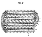
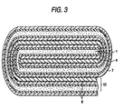
- Figs. 1 through 3 each show a schematic cross section of the main part of the lithium ion secondary battery according to an embodiment of the invention.
- Fig. 4(a) and 4(b) are each a schematic cross section illustrating the structure of the laminate shown in Figs. 1 through 3.
- Fig. 4(b) is an enlarged partial view of the adhesive resin layer of Fig. 4(a).
- the laminate 12 is made up of a positive electrode 1 comprising a positive electrode current collector 2 made of metal, e.g., aluminum foil, having formed thereon a positive electrode active material layer 3; a negative electrode 4 comprising a negative electrode current collector 5 made of metal, e.g., copper, having formed thereon a negative electrode active material layer 6; a separator 7 holding an electrolytic solution containing lithium ions; and adhesive resin layers 8 which join the positive electrode 1 and the negative electrode to the separator 7.
- a positive electrode 1 comprising a positive electrode current collector 2 made of metal, e.g., aluminum foil, having formed thereon a positive electrode active material layer 3
- a negative electrode 4 comprising a negative electrode current collector 5 made of metal, e.g., copper, having formed thereon a negative electrode active material layer 6
- separator 7 holding an electrolytic solution containing lithium ions
- adhesive resin layers 8 which join the positive electrode 1 and the negative electrode to the separator 7.
- Fig. 1 shows a structure in which positive electrodes 1 and negative electrodes 4 are alternately arranged among a plurality of cut sheets of separators 7.
- Figs. 2 and 3 show a structure in which positive electrodes 1 and negative electrodes 4 are alternately arranged between a rolled pair of separators 7. While not shown, the positive electrodes 1 and the negative electrodes 4 can alternate between a folded pair of separators.
- the adhesive resin layer 8 has a mixed phase made up of a polymer solid phase 11, a polymer gel phase 10 containing an electrolytic solution, and an electrolytic solution phase 9 which is held in fine pores formed in the polymer solid phase 11 or the polymer gel phase 10.
- the polymer solid phase 11 of the adhesive resin layer 8 functions to firmly join (adhere) the positive electrode 1 to one side of the separator 7, and the negative electrode 4 to the other side of the separator 7.
- the electrolytic solution phase 9 affords high ion conductivity.
- the polymer gel phase 10 serves not only to prevent reduction in joint (adhesive) strength between the polymer solid phase 11 and the electrolytic solution phase 9 due to mutual dissolution but to retain the high ion conductivity, thereby securing extremely high ion conductivity among the separator 7, the positive electrode 1, and the negative electrode 4.
- An adhesive prepared by dissolving polymeric materials having different average molecular weights in a solvent is used so that the adhesive resin layer 8 may form the polymer solid phase 11 and the polymer gel phase 10.
- the adhesive to be used is a uniform solution of a polymeric material that swells in an electrolytic solution (polymer of lower molecular weight) and a polymeric material that does not swell in an electrolytic solution (polymer of higher molecular weight) in an appropriate solvent.
- the positive electrode 1 and the negative electrode 4 are joined to the separator 7 with the adhesive.
- After the adhesive is thoroughly dried, it is impregnated with an electrolytic solution at a prescribed temperature thereby to form the adhesive resin layer 8 having a mixed phase composed of the polymer solid phase 11 comprising the higher molecular polymer, the gel phase 10 comprising the lower molecular polymer, and the electrolytic solution phase 9.
- the polymeric materials having different average molecular weights may be of a kind or different kinds.
- a combination of polymeric materials different in kind but equal in average molecular weight can form a gel phase and a solid phase.
- polymeric materials different in kind but close in molecular weight are used, it is likely that the gel state changes with time due to development of so-called topological entanglement in a solution system, which can result in change of battery characteristics.
- the polymeric materials which can be used to form the adhesive resin layer 8 must neither dissolve in an electrolytic solution nor react in a lithium ion secondary battery. They are also required to provide a gel phase and a solid phase in the presence of an electrolytic solution. Any polymeric materials that satisfy these conditions are employable.
- a polymeric material can take a gel state or a solid state depending on the kind of the solvent of an electrolytic solution or the thermal history in the preparation of a lithium ion secondary battery.
- Positive electrode active materials which can be used in the positive electrode active material layer 3 include complex oxides of lithium and a transition metal, such as cobalt, manganese or nickel; chalcogen compounds containing lithium; or complex compounds thereof; and these complex oxides, chalcogen compounds or complex oxides to which various dopant elements have been added.
- Negative electrode active materials that can be used in the negative electrode active material layer 6 include any materials capable of intercalating and disintercalating lithium ions, such as carbonaceous materials.
- any metal stable within a battery can be used as a positive electrode current collector 2 and a negative electrode current collector 5.
- Aluminum is preferred as a positive electrode current collector 2, and copper is preferred as a negative electrode current collector 5.
- the current collectors 2 and 5 may have any form, such as foil, net or expanded metal. Those presenting a large void area, such as net and expanded metal, are preferred for obtaining joint strength to the active material layers 3 and 6 and for facilitating impregnation with an electrolytic solution after joining.
- Any insulating material that can be impregnated with an electrolytic solution and has sufficient strength can be used as a separator 7.
- a porous film of polyethylene, polypropylene, etc. is preferably used for adhesiveness and safety.
- Separators made of some of fluorocarbon resins need plasma surface treatment to improve adhesion.
- the electrolytic solution which can be used includes a solution of an electrolyte, such as LiPF 6 , LiClO 4 , LiBF 4 , LiCF 3 SO 3 , LiN(CF 3 SO 2 ) 2 , LiC(CF 3 SO 2 ) 3 or LiN(C 2 F 5 SO 2 ) 2 , in an ether solvent, such as dimethoxyethane, diethoxyethane, dimethyl ether, and diethyl ether, an ester solvent, such as ethylene carbonate, propylene carbonate, dimethyl carbonate, and diethyl carbonate, or a mixture thereof.
- an electrolyte such as LiPF 6 , LiClO 4 , LiBF 4 , LiCF 3 SO 3 , LiN(CF 3 SO 2 ) 2 , LiC(CF 3 SO 2 ) 3 or LiN(C 2 F 5 SO 2 ) 2
- an ether solvent such as dimethoxyethane, diethoxyethane, dimethyl ether, and dieth
- the lithium ion secondary battery of the invention will now be illustrated in greater detail with reference to Examples, but the present invention is by no means limited thereto.
- NMP N-methylpyrrolidone
- the paste was applied with a doctor blade to a coating thickness of 300 ⁇ m to form a positive electrode active material film.
- a 30 ⁇ m thick aluminum net as a positive electrode current collector 2 was placed thereon, and the positive electrode active material paste was again spread on the net with a doctor blade to a thickness of 300 ⁇ m.
- the double-coated aluminum net was allowed to stand in a drier kept at 60°C for 60 minutes to make the paste layers half-dried.
- the resulting laminate composed of the positive electrode current collector 2 and the positive electrode active material was rolled to a thickness of 400 ⁇ m to prepare a positive electrode 1 having positive electrode active material layers 3.
- the positive electrode 1 was immersed in an electrolytic solution.
- the peel strength between the positive electrode active material layer and the positive electrode current collector measured after the immersion was found to be 20 to 25 gf/cm.
- the negative electrode 4 was immersed in an electrolytic solution.
- the peel strength between the negative electrode active material layer 6 and the negative electrode current collector 5 measured after the immersion was found to be 5 to 10 gf/cm.
- the adhesive thus prepared was applied to a side each of two porous polypropylene sheets (Cellguard #2400, produced by Hoechest) used as a pair of separators 7. Before the adhesive dried, the above-prepared positive electrode 1 (or negative electrode) was sandwiched and joined in between the separators 7, and the laminate was dried at 60°C for 2 hours. NMP evaporated from the adhesive to give a porous film having open cells.
- the pair of the separators 7 having the positive electrode 1 (or negative electrode) bonded therebetween was punched to obtain a cut piece of prescribed size.
- the adhesive was applied to one side of the cut piece, and a cut piece of the negative electrode 4 (or positive electrode) having a prescribed size was stuck thereto.
- the adhesive was then applied to a side of another cut piece of the separator 7 having a prescribed size, and the coated side was stuck to the negative electrode 4 (or positive electrode) which had been stuck to the laminate.
- the above-described steps were repeated to build up a battery body having a plurality of electrode laminates.
- the battery body was dried while applying pressure to prepare a tabular laminated battery body as shown in Fig. 1.
- the tabular laminated battery body was immersed in an electrolytic prepared by dissolving LiPF 6 in a 1:1 (by mole) mixed solvent of ethylene carbonate and dimethyl carbonate in a concentration of 1.0 mol/dm 3 at room temperature to infiltrate the electrolytic solution into the battery body.
- the peel strength between the positive electrode active material layer 3 and the separator 7 and between the negative electrode active material layer 6 and the separator 7 was 25 to 30 gf/cm and 15 to 20 gf/cm, respectively, as measured in accordance with JIS K6854.
- the impregnated tabular laminated battery body was put in an aluminum laminated film pack, and the opening of the pack was heat-sealed to complete a lithium ion secondary battery.
- a battery having the tabular laminated battery body sheen in Fig. 1 was prepared in the same manner as in Example 1, except for changing the adhesive preparation as described below.
- a battery having the tabular laminated battery body shown in Fig. 1 was prepared in the same manner as in Example 1, except for changing the adhesive preparation as described below.
- a battery having the tabular laminated battery body shown in Fig. 1 was prepared in the same manner as in Example 1, except for changing the adhesive preparation as described below.
- a battery having the tabular laminated battery body shown in Fig. 1 was prepared in the same manner as in Example 1, except for changing the adhesive preparation as described below.
- a battery having the tabular laminated battery body shown in Fig. 1 was prepared in the same manner as in Example 1, except for altering the adhesive preparation and the electrolytic solution used in the preparation of the battery as described below.
- LiPF 6 (produced by Tokyo Kasei) was dissolved in a 1:1 (by mole) mixed solvent of ethylene carbonate (produced by Kanto Chemical) and diethyl carbonate (produced by Wako Pure Chemical) in a concentration of 1.0 mol/dm 3 .
- a battery having the tabular laminated battery body shown in Fig. 1 was prepared in the same manner as an Example 6, except for altering the adhesive preparation as described below.
- Mw average molecular weight
- Mw average molecular weight
- a battery having the tabular laminated battery body shown in Fig. 1 was prepared in the same manner as an Example 6, except for changing the adhesive preparation as described below.
- a battery having the tabular laminated battery body shown in Fig. 1 was prepared in the same manner as in Example 1, except for altering the adhesive preparation as described below and changing the temperature for infiltrating the electrolytic solution in the preparation of the battery body to 70°C.
- a battery having the tabular laminated battery body shown in Fig. 1 was prepared in the same manner as in Example 1, except for changing the adhesive preparation as described below.
- a battery having the tabular laminated battery body shown in Fig. 1 was prepared in the same manner as in Example 1, except for changing the adhesive preparation as described below.
- Lithium ion secondary batteries having the tabular laminated battery body shown in Fig. 2 were prepared by using the positive and the negative electrodes described in Example 1 and the adhesives described in Examples 1 to 11.
- the adhesive was applied to a side of two porous polypropylene sheets (Cellguard #2400, produced by Hoechest) as two separators 7 of band form.
- the negative electrode 4 (or positive electrode) of band form was sandwiched and stuck between the two separators with their coated side inward, and the laminate was put in a warm air drier at 60°C for 2 hours to evaporate NMP.
- the adhesive was then applied to one of the paired separators 7 of band form having the negative electrode 4 (or positive electrode) therebetween.
- One end of the adhesive-coated separator 7 was folded back at a prescribed length while inserting the positive electrode 1 (or negative electrode) into the fold, and the laminate was passed through a laminator.
- the adhesive was applied to the other separator 7 of band form, and another piece of the positive electrode 1 (or negative electrode) was stuck thereto at the position corresponding to the positive electrode 1 (or negative electrode) having been inserted into the fold.
- the paired separators were rolled up to make an oblong ellipsoid.
- the separators were again rolled up with a still another cut piece of the positive electrode (or negative electrode) inserted therein. These steps were repeated to form a battery body having a plurality of electrode laminates.
- the battery body was dried under pressure to obtain a tabular roll type laminated battery body as shown in Fig. 2.
- the tabular laminated battery body was immersed in an electrolytic solution of 1.0 mol/dm 3 of lithium hexafluorophosphate in a mixed solvent (1:1 by mole) of ethylene carbonate and diamethyl carbonate and heat-sealed into an aluminum laminate film pack to make a battery.
- Example 12 has shown an example in which a pair of separators 7 is rolled up
- the battery body may be such that is prepared by repeating a step of folding a pair of separator bands having a negative electrode 4 (or positive electrode) of band form joined therebetween while sticking a cut piece of a positive electrode 1 (or negative electrode) into each fold.
- Lithium ion secondary batteries having the tabular laminated battery body shown in Fig. 3 were prepared by using the positive and the negative electrodes shown in Example 1 and the adhesives shown in Examples 1 to 11.
- the difference from Example 12 lies in that a laminate of a positive electrode, a negative electrode, and separators ware rolled up simultaneously.
- the negative electrode 4 (or positive electrode) of band form was set between a pair of porous polypropylene sheets (Cellguard #2400, produced by Hoechest) as separators 7, and the positive electrode 1 (or negative electrode) of band form was placed on the outer side of one of the separators 7 with a prescribed length of its starting end sticking out over the end of that separator 7.
- the adhesive was applied to the inner sides of the paired separators 7 and the outer side of the separator 7 on which the positive electrode 1 (or negative electrode) had been arranged.
- the positive electrode 1 (or negative electrode), the two separators 7, and the negative electrode 4 (or positive electrode) were stuck together and passed through a laminator.
- the adhesive was applied to the outer side of the other separator 7, and the sticking end of the positive electrode 1 (or negative electrode) was folded back and stuck to the coated side of the separator 7.
- the laminate was rolled up in such a manner that the folded positive electrode 1 (or negative electrode) might be wrapped in, making an oblong ellipsoid, to form a battery body comprising a plurality of electrode laminates.
- the battery body was dried under pressure to prepare a tabular roll type laminated battery body.
- the tabular laminated battery body was immersed in an electrolytic solution comprising an ethylene carbonate/dimethyl carbonate mixed solvent (1:1 by mole) having dissolved therein 1.0 mol/dm 3 of LiPF 6 and heat-sealed into an aluminum laminate film pack to complete a battery.
- a lithium ion secondary battery was prepared in the same manner as an Example 1, except for changing the adhesive preparation as described below.
- Mw average molecular weight
- a lithium ion secondary battery having the tabular laminated battery body shown in Fig. 1 was prepared in the same manner as in Example 1, except for changing the adhesive preparation as described below.
- Mw average molecular weight
- a lithium ion secondary battery was prepared in the same manner as in Example 1, except for changing the adhesive preparation as described below.
- Mw average molecular weight
- a lithium ion secondary battery having the tabular laminated battery body shown in Fig. 1 was prepared in the same manner as in Example 1, except for changing the adhesive preparation as described below.
- Mw average molecular weight
- a lithium ion secondary battery having the tabular laminated battery body shown in Fig. 1 was prepared in the same manner as in Example 1, except for using the same adhesive as used in Examples 6 and 9 and changing the temperature for infiltrating the electrolytic solution in the preparation of the battery body to 100°C.
- the characteristics of the lithium ion secondary batteries obtained in Examples 1 to 11 and Comparative Examples 1 to 5 were evaluated.
- Table 1 shows the results of measurements of cell resistivity and adhesive strength (peel strength) between the positive active material and the separator and between the negative active material and the separator in the batteries of Examples 1 to 11 and Comparative Examples 1 to 5.
- Fig. 5 shows the results of an over charge test (200% charge).
- Fig. 6 shows the results of an over discharge test.
- (A) and (B) indicate charge characteristics and discharge characteristics, respectively. While Figs. 5 and 6 show the results of the lithium ion secondary batteries of Examples 6 to 8, other Examples gave equal results.
- Example 1 0 (unmeasurable) 0 (unmeasurable) unmeasurable Compara.
- Example 2 0 (unmeasurable) 0 (unmeasurable) unmeasurable Compara.
- Example 3 0 (unmeasurable) 0 (unmeasurable) unmeasurable Compara.
- Example 4 52 61 150 Compara.
- Example 5 0 (unmeasurable) 0 (unmeasurable) unmeasurable
- the lithium ion secondary battery of Comparative Example 4 while showing a great peel strength, had a high resistivity due to low ion conductivity.
- the lithium ion secondary battery of Comparative Example 5 had an unmeasurable peel strength close to zero and an unmeasurably high resistivity.
- the adhesive used in Comparative Example 5 had the same composition as in Examples 6 and 9, the impregnating electrolytic solution as high as 100°C swelled the high polymer that does not swell in low temperatures. It followed that the adhesive failed to retain the adhesive strength similarly to Comparative Examples 1 to 3, while the ion conductivity appeared to increase.
- the lithium ion secondary batteries of Examples 1 to 11 secure both ion conductivity and adhesive strength, having a cell resistivity of 20 to 30 ⁇ and a peel strength of 12 to 52 gf/cm.
- the adhesive resin layer has a mixed phase of a polymer gel phase containing the electrolytic solution and a polymer solid phase.
- the polymer gel phase containing the electrolytic solution serves for ion conduction, while the polymer solid state achieves adhesive strength.
- the present invention provides batteries which can have reduced size and weight and a arbitrary shape as well as improved performance and can be used in portable electronic equipment, such as portable personal computers and cellular phones.
Landscapes
- Chemical & Material Sciences (AREA)
- Engineering & Computer Science (AREA)
- Manufacturing & Machinery (AREA)
- Chemical Kinetics & Catalysis (AREA)
- Electrochemistry (AREA)
- General Chemical & Material Sciences (AREA)
- Materials Engineering (AREA)
- Physics & Mathematics (AREA)
- Condensed Matter Physics & Semiconductors (AREA)
- Dispersion Chemistry (AREA)
- General Physics & Mathematics (AREA)
- Inorganic Chemistry (AREA)
- Secondary Cells (AREA)
Abstract
An object as to provide a practical and stable lithium ion
secondary battery which can take a compact, thin, and arbitrary shape,
needs no firm battery case, and yet secures both ion conduction and
adhesive strength and a process for producing the same. The battery
structure comprises a plurality of laminates (12) each having a
separator (3) holding an Li ion-containing nonaqueous electrolyte
to which a positive electrode (1) and a negative electrode (2) are
joined with an adhesive resin layer (8) having a mixed phase composed
of an electrolytic solution phase (9), a polymer gel phase (10)
containing an electrolytic solution, and a polymer solid phase (11).
Description
This invention relates to a lithium ion secondary battery
comprising a positive electrode and a negative electrode facing each
other via a separator supporting an electrolyte. More particularly,
it relates to a thin type lithium ion secondary battery having
excellent charge and discharge characteristics.
There has been an eager demand for reduction in size and
weight of portable electronic equipment. To meet the demand, it
is required not only to improve battery performance, such as high
voltage, high energy density, and resistance to high load, but to
widen the freedom of shape design and to secure safety. Development
and improvement of a variety of batteries have been proceeding along
these lines. Of currently available batteries, lithium ion
batteries are the most promising secondary batteries for realizing
a high voltage, a high energy density, and resistance to high load
and the most expected to fulfill the above-described requirements.
A lithium ion secondary battery mainly comprises a positive
electrode, a negative electrode, and an ion conducting layer
interposed between the electrodes. The lithium ion secondary
batteries that have been put to practical use employ a positive plate
prepared by mixing a powdered active material, such as a
lithium-cobalt complex oxide, and a powdered electron conductor
with a binder resin and applying the mixture to an aluminum current
collector; a negative plate prepared by mixing a powdered
carbonaceous active material with a binder resin and applying the
mixture to a copper current collector; and an ion conducting layer
made of a porous film of polyethylene, polypropylene, etc. filled
with a nonaqueous solvent containing lithium ions.
In the lithium ion secondary batteries that have been put
to practical use, electrical connections among the positive
electrode, the ion conducting layer, and the negative electrode are
maintained by pressure application by using a firm battery case made
of stainless steel, etc. However, such a case increases the weight
of a lithium ion secondary battery to make it difficult to realize
size and weight reduction. Moreover, the rigidness of the case
narrows the freedom of shape design.
In order to achieve size and weight reduction and freedom
of shape design of a lithium ion secondary battery, it is necessary
to bond an ion conducting layer to a positive electrode and to a
negative electrode and to maintain the joined state without applying
pressure from the outside.
In this connection, U.S. Patent 5,437,692 discloses a
structure in which a lithium ion-conducting polymer is used as an
ion conducting layer, and a positive electrode and a negative
electrode are joined to the ion-conducting layer with an adhesive
layer containing a lithium compound. WO95/15589 discloses a
structure having a plastic ion-conducting layer to which a positive
and a negative electrode are joined.
According to the method taught in U.S. Patent 5,437,692
supra, however, the joint strength attained is not enough, the
battery cannot be made sufficiently thin, and the ion conduction
resistance between the positive and the negative electrodes through
the ion-conducting layer is high so that the battery characteristics
such as charge and discharge characteristics are insufficient for
practical use. According to WO95/15589 supra, the ion-conducting
layer, being plastic, cannot secure sufficient joint strength, and
the thickness of the battery cannot be reduced sufficiently.
The present invention has been made in order to solve these
problems. It provides a battery structure in which a positive and
a negative electrode are brought into intimate contact with an
ion-conducting layer (hereinafter referred to as a separator) with
an adhesive resin to secure sufficient joint strength among the
electrodes and the separator while suppressing ion conduction
resistance among them on the same level as in a conventional battery
put in a case.
A first lithium ion secondary battery according to the
present invention comprises a plurality of laminates each having
a separator holding an electrolytic solution to which a positive
electrode and a negative electrode are joined with an adhesive resin
layer having a mixed phase composed of an electrolytic solution phase,
a polymer gel phase containing an electrolytic solution, and a
polymer solid phase.
A second lithium ion secondary battery of the invention is
the above-described 1st battery, wherein the plurality of laminates
are formed by interposing the positive electrode and the negative
electrode alternately among a plurality of cut sheets of the
separator.
A third lithium ion secondary battery of the invention is
the above-described 1st battery, wherein the plurality of laminates
are formed by interposing the positive electrode and the negative
electrode alternately between rolled separators.
A fourth lithium ion secondary battery of the invention is
the above-described 1st battery, wherein the plurality of laminates
are formed by interposing the positive electrode and the negative
electrode alternately between folded separators.
A fifth lithium ion secondary battery of the invention is
the above-described first battery, wherein the polymer gel phase
and the polymer solid phase contain the same kind or different kinds
of polymeric materials, and the polymeric material contained in the
polymer gel phase and that contained in the polymer solid phase have
different average molecular weights.
A sixth lithium ion secondary battery of the invention is
the above-described first battery, wherein the polymer gel phase
and the polymer solid phase contain polyvinylidene fluoride, and
the polyvinylidene fluoride contained in the polymer gel phase and
that contained in the polymer solid phase are different in average
molecular weight.
A seventh lithium ion secondary battery of the invention
is the above-described first battery, wherein the polymer gel phase
and the polymer solid phase contain polyvinyl alcohol, and the
polyvinyl alcohol contained in the polymer gel phase and that
contained in the polymer solid phase are different in average
molecular weight.
In the first to seventh lithium ion secondary batteries,
both joint strength and ion conductivity among the positive
electrode, the negative electrode, and the separator can be obtained
by adhesion with the above-mentioned adhesive resin layer which has
a mixed phase made up of an electrolytic solution phase, a polymer
gel phase containing an electrolytic solution, and a polymer solid
phase. Owing to the adhesive strength and high ion conductivity
thus secured, there is provided a practical compact lithium ion
secondary battery of laminated electrode type which has a plurality
of electrode laminates and yet requires no firm battery case and
has high performance and a large capacity.
A process for producing the first lithium ion secondary
battery according to the present invention is a process for producing
a lithium ion secondary battery comprising a plurality of laminates
each having a separator holding an electrolytic solution to which
a positive electrode and a negative electrode are joined, which
comprises coating the facing sides of a plurality of separators with
an adhesive comprising two or more polymeric materials different
in average molecular weight dissolved in a solvent, joining a
positive electrode and a negative electrode alternately among the
plurality of the separators via an adhesive resin layer to form a
battery body, and impregnating the battery body with an electrolytic
solution to make the adhesive resin layer a mixed phase composed
of a polymer gel phase containing the electrolytic solution, a
polymer solid phase, and an electrolytic solution phase. On being
impregnated with an electrolytic solution, the adhesive resin layer
becomes a mixed phase composed of a polymer gel phase containing
the electrolytic solution, a polymer solid phase, and a layer of
the electrolytic solution. Both the joint strength and ion
conductivity between each of the positive and negative electrodes
and the separator can be secured thereby. The thus laminated units
can be piled to provide a practical and stable lithium ion secondary
battery which can take a compact, thin, and arbitrary shape, having
no firm battery case, and also exhibits high charge and discharge
efficiency.
The practice in carrying out the present invention will be
described by referring to the accompanying drawings.
Figs. 1 through 3 each show a schematic cross section of
the main part of the lithium ion secondary battery according to an
embodiment of the invention. Fig. 4(a) and 4(b) are each a schematic
cross section illustrating the structure of the laminate shown in
Figs. 1 through 3. Fig. 4(b) is an enlarged partial view of the
adhesive resin layer of Fig. 4(a).
In Figs. 1 through 4, numeral 12 indicates a laminate. The
laminate 12 is made up of a positive electrode 1 comprising a positive
electrode current collector 2 made of metal, e.g., aluminum foil,
having formed thereon a positive electrode active material layer
3; a negative electrode 4 comprising a negative electrode current
collector 5 made of metal, e.g., copper, having formed thereon a
negative electrode active material layer 6; a separator 7 holding
an electrolytic solution containing lithium ions; and adhesive
resin layers 8 which join the positive electrode 1 and the negative
electrode to the separator 7.
Fig. 1 shows a structure in which positive electrodes 1 and
negative electrodes 4 are alternately arranged among a plurality
of cut sheets of separators 7. Figs. 2 and 3 show a structure in
which positive electrodes 1 and negative electrodes 4 are
alternately arranged between a rolled pair of separators 7. While
not shown, the positive electrodes 1 and the negative electrodes
4 can alternate between a folded pair of separators.
As shown in Fig. 4(b), the adhesive resin layer 8 has a mixed
phase made up of a polymer solid phase 11, a polymer gel phase 10
containing an electrolytic solution, and an electrolytic solution
phase 9 which is held in fine pores formed in the polymer solid phase
11 or the polymer gel phase 10.
The polymer solid phase 11 of the adhesive resin layer 8
functions to firmly join (adhere) the positive electrode 1 to one
side of the separator 7, and the negative electrode 4 to the other
side of the separator 7. The electrolytic solution phase 9 affords
high ion conductivity. The polymer gel phase 10 serves not only
to prevent reduction in joint (adhesive) strength between the
polymer solid phase 11 and the electrolytic solution phase 9 due
to mutual dissolution but to retain the high ion conductivity,
thereby securing extremely high ion conductivity among the
separator 7, the positive electrode 1, and the negative electrode
4.
An adhesive prepared by dissolving polymeric materials
having different average molecular weights in a solvent is used so
that the adhesive resin layer 8 may form the polymer solid phase
11 and the polymer gel phase 10.
That is, the adhesive to be used is a uniform solution of
a polymeric material that swells in an electrolytic solution
(polymer of lower molecular weight) and a polymeric material that
does not swell in an electrolytic solution (polymer of higher
molecular weight) in an appropriate solvent. The positive
electrode 1 and the negative electrode 4 are joined to the separator
7 with the adhesive. After the adhesive is thoroughly dried, it
is impregnated with an electrolytic solution at a prescribed
temperature thereby to form the adhesive resin layer 8 having a mixed
phase composed of the polymer solid phase 11 comprising the higher
molecular polymer, the gel phase 10 comprising the lower molecular
polymer, and the electrolytic solution phase 9.
The polymeric materials having different average molecular
weights may be of a kind or different kinds. A combination of
polymeric materials different in kind but equal in average molecular
weight can form a gel phase and a solid phase. In such a case, too,
it is preferred that the polymeric materials be different in average
molecular weight for the following reason. Where polymeric
materials different in kind but close in molecular weight are used,
it is likely that the gel state changes with time due to development
of so-called topological entanglement in a solution system, which
can result in change of battery characteristics.
The polymeric materials which can be used to form the
adhesive resin layer 8 must neither dissolve in an electrolytic
solution nor react in a lithium ion secondary battery. They are
also required to provide a gel phase and a solid phase in the presence
of an electrolytic solution. Any polymeric materials that satisfy
these conditions are employable. A polymeric material can take a
gel state or a solid state depending on the kind of the solvent of
an electrolytic solution or the thermal history in the preparation
of a lithium ion secondary battery. Examples of polymeric materials
which can be a gel phase
under the condition of this application
include acrylic ester polymers, such as
polymethyl methacrylate, polyacrylonitrile, low-molecular weight
polyvinylidene fluoride, and copolymers comprising these polymers
and other polymers; low-molecular weight polyvinyl alcohol and
copolymers comprising the low-molecular weight polyvinyl alcohol
and other polymers; and mixtures mainly comprising low-molecular
weight polyvinyl alcohol. Examples of polymeric materials which
can be a solid phase
under the condition of this application
include high-molecular weight polyvinylidene
fluoride, polytetrafluoroethylene, and copolymers of those
polymers and other polymers; high-molecular weight polyvinyl
alcohol and copolymers of the high-molecular weight polyvinyl
alcohol and other polymers; and mixtures mainly comprising
high-molecular weight polyvinyl alcohol.
Positive electrode active materials which can be used in
the positive electrode active material layer 3 include complex
oxides of lithium and a transition metal, such as cobalt, manganese
or nickel; chalcogen compounds containing lithium; or complex
compounds thereof; and these complex oxides, chalcogen compounds
or complex oxides to which various dopant elements have been added.
Negative electrode active materials that can be used in the negative
electrode active material layer 6 include any materials capable of
intercalating and disintercalating lithium ions, such as
carbonaceous materials.
Any metal stable within a battery can be used as a positive
electrode current collector 2 and a negative electrode current
collector 5. Aluminum is preferred as a positive electrode current
collector 2, and copper is preferred as a negative electrode current
collector 5. The current collectors 2 and 5 may have any form, such
as foil, net or expanded metal. Those presenting a large void area,
such as net and expanded metal, are preferred for obtaining joint
strength to the active material layers 3 and 6 and for facilitating
impregnation with an electrolytic solution after joining.
Any insulating material that can be impregnated with an
electrolytic solution and has sufficient strength, such as porous
film, net, and nonwoven fabric, can be used as a separator 7. A
porous film of polyethylene, polypropylene, etc. is preferably used
for adhesiveness and safety. Separators made of some of
fluorocarbon resins need plasma surface treatment to improve
adhesion.
The electrolytic solution which can be used includes a
solution of an electrolyte, such as LiPF6, LiClO4, LiBF4, LiCF3SO3,
LiN(CF3SO2)2, LiC(CF3SO2)3 or LiN(C2F5SO2)2, in an ether solvent, such
as dimethoxyethane, diethoxyethane, dimethyl ether, and diethyl
ether, an ester solvent, such as ethylene carbonate, propylene
carbonate, dimethyl carbonate, and diethyl carbonate, or a mixture
thereof.
The lithium ion secondary battery of the invention will now
be illustrated in greater detail with reference to Examples, but
the present invention is by no means limited thereto.
Eighty-seven parts by weight of LiCoO2, 8 parts by weight
of graphite powder, and 5 parts of polyvinylidene fluoride were
dispersed in N-methylpyrrolidone (hereinafter abbreviated as NMP)
to prepare positive electrode active material paste. The paste was
applied with a doctor blade to a coating thickness of 300 µm to form
a positive electrode active material film. A 30 µm thick aluminum
net as a positive electrode current collector 2 was placed thereon,
and the positive electrode active material paste was again spread
on the net with a doctor blade to a thickness of 300 µm. The
double-coated aluminum net was allowed to stand in a drier kept at
60°C for 60 minutes to make the paste layers half-dried. The
resulting laminate composed of the positive electrode current
collector 2 and the positive electrode active material was rolled
to a thickness of 400 µm to prepare a positive electrode 1 having
positive electrode active material layers 3. The positive
electrode 1 was immersed in an electrolytic solution. The peel
strength between the positive electrode active material layer and
the positive electrode current collector measured after the
immersion was found to be 20 to 25 gf/cm.
Ninety-five parts by weight of Mesophase Microbead Carbon
(a trade name, produced by Osaka Gas Co., Ltd.) and 5 parts by weight
of polyvinylidene fluoride were dispersed in NMP to prepare negative
electrode active material paste. The paste was applied with a
doctor blade to a thickness of 300 µm to make a negative electrode
active material film. A 20 µm thick copper net as a negative
electrode current collector was placed thereon, and the negative
electrode active material paste was again spread thereon with a
doctor blade to a thickness of 300 µm. The laminate was allowed
to stand in a drier at 60°C for 60 minutes to make the paste half-dried.
The resulting laminate composed of the negative electrode current
collector 5 and the negative electrode active material was rolled
to a thickness of 400 µm to prepare a negative electrode 4 having
negative electrode active material layers 6.
The negative electrode 4 was immersed in an electrolytic
solution. The peel strength between the negative electrode active
material layer 6 and the negative electrode current collector 5
measured after the immersion was found to be 5 to 10 gf/cm.
A mixture of 3.0 parts by weight of polymethyl methacrylate
having an average molecular weight (Mw) of 350,000 (produced by
Aldrich), 2.0 parts by weight of polyvinylidene fluoride having an
average molecular weight (Mw) of 534,000 (produced by Aldrich), and
95 parts by weight of NMP was thoroughly stirred to prepare a uniform
and viscous adhesive.
The adhesive thus prepared was applied to a side each of
two porous polypropylene sheets (Cellguard #2400, produced by
Hoechest) used as a pair of separators 7. Before the adhesive dried,
the above-prepared positive electrode 1 (or negative electrode) was
sandwiched and joined in between the separators 7, and the laminate
was dried at 60°C for 2 hours. NMP evaporated from the adhesive
to give a porous film having open cells.
The pair of the separators 7 having the positive electrode
1 (or negative electrode) bonded therebetween was punched to obtain
a cut piece of prescribed size. The adhesive was applied to one
side of the cut piece, and a cut piece of the negative electrode
4 (or positive electrode) having a prescribed size was stuck thereto.
The adhesive was then applied to a side of another cut piece of
the separator 7 having a prescribed size, and the coated side was
stuck to the negative electrode 4 (or positive electrode) which had
been stuck to the laminate. The above-described steps were repeated
to build up a battery body having a plurality of electrode laminates.
The battery body was dried while applying pressure to prepare a
tabular laminated battery body as shown in Fig. 1.
Current collecting tabs each connected to the end of every
positive current collectors and every negative current collectors
of the tabular laminated battery body were spot-welded among the
positive electrodes and among the negative electrodes, respectively,
to complete parallel electrical connections in the tabular
laminated battery body.
The tabular laminated battery body was immersed in an
electrolytic prepared by dissolving LiPF6 in a 1:1 (by mole) mixed
solvent of ethylene carbonate and dimethyl carbonate in a
concentration of 1.0 mol/dm3 at room temperature to infiltrate the
electrolytic solution into the battery body.
The peel strength between the positive electrode active
material layer 3 and the separator 7 and between the negative
electrode active material layer 6 and the separator 7 was 25 to
30 gf/cm and 15 to 20 gf/cm, respectively, as measured in accordance
with JIS K6854.
The impregnated tabular laminated battery body was put in
an aluminum laminated film pack, and the opening of the pack was
heat-sealed to complete a lithium ion secondary battery.
A battery having the tabular laminated battery body sheen
in Fig. 1 was prepared in the same manner as in Example 1, except
for changing the adhesive preparation as described below.
A mixture of 3.0 parts by weight of polyacrylonitrile
having an average molecular might (Mw) of 86,200 (produced by
Aldrich), 2.0 parts by weight of polyvinylidene fluoride having an
average molecular weight (Mw) of 534,000 (produced by Aldrich), and
95 parts by weight of NMP was thoroughly stirred to prepare a uniform
and viscous adhesive.
A battery having the tabular laminated battery body shown
in Fig. 1 was prepared in the same manner as in Example 1, except
for changing the adhesive preparation as described below.
A mixture of 2.5 parts by weight of polyvinylidene fluoride
having an average molecular might (Mw) of 180,000 (produced by
Aldrich), 2.5 parts by weight of polyvinylidene fluoride having an
average molecular weight (Mw) of 534,000 (produced by Aldrich), and
95 parts by weight of NMP was thoroughly stirred to prepare a uniform
and viscous adhesive.
A battery having the tabular laminated battery body shown
in Fig. 1 was prepared in the same manner as in Example 1, except
for changing the adhesive preparation as described below.
A mixture of 3.5 parts by weight of polyvinylidene fluoride
having a average molecular might (Mw) of 180,000 (produced by
Aldrich), 3.5 parts by might of polyvinylidene fluoride having an
average molecular weight (Mw) of 534,000 (produced by Aldrich), and
93 parts by weight of NMP was thoroughly stirred to prepare a uniform
and viscous adhesive.
A battery having the tabular laminated battery body shown
in Fig. 1 was prepared in the same manner as in Example 1, except
for changing the adhesive preparation as described below.
A mixture of 5.0 parts by weight of polyvinylidene fluoride
having an average molecular weight (Mw) of 180,000 (produced by
Aldrich), 5.0 parts by weight of polyvinylidene fluoride having an
average molecular weight (Mw) of 534,000 (produced by Aldrich), and
90 parts by weight of NMP was thoroughly stirred to prepare a uniform
and viscous adhesive.
A battery having the tabular laminated battery body shown
in Fig. 1 was prepared in the same manner as in Example 1, except
for altering the adhesive preparation and the electrolytic solution
used in the preparation of the battery as described below.
A mixture of 2.5 parts by weight of polyvinylidene fluoride
having an average molecular weight (Mw) of 180,000 (produced by
Aldrich), 2.5 parts by weight of polyvinylidene fluoride having an
average molecular weight (Mw) of 534,000 (produced by Aldrich), and
9 parts by weight of NMP was thoroughly stirred to prepare a uniform
and viscous adhesive.
LiPF6 (produced by Tokyo Kasei) was dissolved in a 1:1 (by
mole) mixed solvent of ethylene carbonate (produced by Kanto
Chemical) and diethyl carbonate (produced by Wako Pure Chemical)
in a concentration of 1.0 mol/dm3.
A battery having the tabular laminated battery body shown
in Fig. 1 was prepared in the same manner as an Example 6, except
for altering the adhesive preparation as described below.
A mixture of 3.5 parts by weight of polyvinylidene fluoride
having an average molecular weight (Mw) of 180,000 (produced by
Aldrich), 3.5 parts by might of polyvinylidene fluoride having an
average molecular weight (Mw) of 534,000 (produced by Aldrich), and
93 parts by weight of NMP was thoroughly stirred to prepare a uniform
and viscous adhesive.
A battery having the tabular laminated battery body shown
in Fig. 1 was prepared in the same manner as an Example 6, except
for changing the adhesive preparation as described below.
A mixture of 5.0 parts by weight of polyvinylidene fluoride
having an average molecular weight (Mw) of 180,000 (produced by
Aldrich), 5.0 parts by might of polyvinylidene fluoride having an
average molecular weight (Mw) of 534,000 (produced by Aldrich), and
90 parts by weight of NMP was thoroughly stirred to prepare a uniform
and viscous adhesive.
A battery having the tabular laminated battery body shown
in Fig. 1 was prepared in the same manner as in Example 1, except
for altering the adhesive preparation as described below and
changing the temperature for infiltrating the electrolytic solution
in the preparation of the battery body to 70°C.
A mixture of 2.5 parts by weight of polyvinylidene fluoride
having an average molecular weight (Mw) of 180,000 (produced by
Aldrich), 2.5 parts by weight of polyvinylidene fluoride having an
average molecular weight (Mw) of 534,000 (produced by Aldrich), and
95 parts by weight of NMP was thoroughly stirred to prepare a uniform
and viscous adhesive.
A battery having the tabular laminated battery body shown
in Fig. 1 was prepared in the same manner as in Example 1, except
for changing the adhesive preparation as described below.
A mixture of 2.5 parts by weight of polyvinyl alcohol having
an average molecular weight (Mw) of 22,000 (produced by Nakarai
Kagaku), 2.5 parts by weight of polyvinyl alcohol having an average
molecular weight (Mw) of 186,000 (produced by Aldrich), and 95 parts
by weight of NMP was thoroughly stirred to prepare a uniform and
viscous adhesive.
A battery having the tabular laminated battery body shown
in Fig. 1 was prepared in the same manner as in Example 1, except
for changing the adhesive preparation as described below.
A mixture of 1.5 parts by weight of polyvinylidene fluoride
having an average molecular weight (Mw) of 180,000, 1.5 parts by
weight of polyvinyl alcohol having an average molecular weight (Mw)
of 22,000, 2.5 parts by weight of polyvinylidene fluoride having
an average molecular weight (Mw) of 534,000, and 94.5 parts by weight
of NMP was thoroughly stirred to prepare a uniform and viscous
adhesive.
Lithium ion secondary batteries having the tabular
laminated battery body shown in Fig. 2 were prepared by using the
positive and the negative electrodes described in Example 1 and the
adhesives described in Examples 1 to 11.
The adhesive was applied to a side of two porous
polypropylene sheets (Cellguard #2400, produced by Hoechest) as two
separators 7 of band form. The negative electrode 4 (or positive
electrode) of band form was sandwiched and stuck between the two
separators with their coated side inward, and the laminate was put
in a warm air drier at 60°C for 2 hours to evaporate NMP.
The adhesive was then applied to one of the paired
separators 7 of band form having the negative electrode 4 (or
positive electrode) therebetween. One end of the adhesive-coated
separator 7 was folded back at a prescribed length while inserting
the positive electrode 1 (or negative electrode) into the fold, and
the laminate was passed through a laminator. Subsequently, the
adhesive was applied to the other separator 7 of band form, and
another piece of the positive electrode 1 (or negative electrode)
was stuck thereto at the position corresponding to the positive
electrode 1 (or negative electrode) having been inserted into the
fold. The paired separators were rolled up to make an oblong
ellipsoid. The separators were again rolled up with a still another
cut piece of the positive electrode (or negative electrode) inserted
therein. These steps were repeated to form a battery body having
a plurality of electrode laminates. The battery body was dried
under pressure to obtain a tabular roll type laminated battery body
as shown in Fig. 2.
Current collector tabs connected to the end of every
positive electrode current collector and the negative electrode
current collector of the resulting tabular laminated battery body
were spot welded to establish parallel electrical connections.
The tabular laminated battery body was immersed in an
electrolytic solution of 1.0 mol/dm3 of lithium hexafluorophosphate
in a mixed solvent (1:1 by mole) of ethylene carbonate and diamethyl
carbonate and heat-sealed into an aluminum laminate film pack to
make a battery.
While Example 12 has shown an example in which a pair of
separators 7 is rolled up, the battery body may be such that is
prepared by repeating a step of folding a pair of separator bands
having a negative electrode 4 (or positive electrode) of band form
joined therebetween while sticking a cut piece of a positive
electrode 1 (or negative electrode) into each fold.
Lithium ion secondary batteries having the tabular
laminated battery body shown in Fig. 3 were prepared by using the
positive and the negative electrodes shown in Example 1 and the
adhesives shown in Examples 1 to 11. The difference from Example
12 lies in that a laminate of a positive electrode, a negative
electrode, and separators ware rolled up simultaneously.
The negative electrode 4 (or positive electrode) of band
form was set between a pair of porous polypropylene sheets (Cellguard
#2400, produced by Hoechest) as separators 7, and the positive
electrode 1 (or negative electrode) of band form was placed on the
outer side of one of the separators 7 with a prescribed length of
its starting end sticking out over the end of that separator 7. The
adhesive was applied to the inner sides of the paired separators
7 and the outer side of the separator 7 on which the positive
electrode 1 (or negative electrode) had been arranged. The positive
electrode 1 (or negative electrode), the two separators 7, and the
negative electrode 4 (or positive electrode) were stuck together
and passed through a laminator. The adhesive was applied to the
outer side of the other separator 7, and the sticking end of the
positive electrode 1 (or negative electrode) was folded back and
stuck to the coated side of the separator 7. The laminate was rolled
up in such a manner that the folded positive electrode 1 (or negative
electrode) might be wrapped in, making an oblong ellipsoid, to form
a battery body comprising a plurality of electrode laminates. The
battery body was dried under pressure to prepare a tabular roll type
laminated battery body.
Current collector tabs connected to the end of the positive
and the negative electrode collectors of the resulting tabular roll
type laminated battery body were spot welded among the positive
electrodes and among the negative electrodes to make parallel
electrical connections.
The tabular laminated battery body was immersed in an
electrolytic solution comprising an ethylene carbonate/dimethyl
carbonate mixed solvent (1:1 by mole) having dissolved therein
1.0 mol/dm3 of LiPF6 and heat-sealed into an aluminum laminate film
pack to complete a battery.
A lithium ion secondary battery was prepared in the same
manner as an Example 1, except for changing the adhesive preparation
as described below.
A mixture of 5.0 parts by weight of polymethyl methacrylate
having an average molecular weight (Mw) of 350,000 and 95 parts by
weight of NMP was thoroughly stirred to prepare a uniform and viscous
adhesive.
A lithium ion secondary battery having the tabular
laminated battery body shown in Fig. 1 was prepared in the same manner
as in Example 1, except for changing the adhesive preparation as
described below.
A mixture of 5.0 parts by weight of polyacrylonitrile having
an average molecular weight (Mw) of 86,200 and 95 parts by weight
of NMP was thoroughly stirred to prepare a uniform and viscous
adhesive.
A lithium ion secondary battery was prepared in the same
manner as in Example 1, except for changing the adhesive preparation
as described below.
A mixture of 5.0 parts by weight of polyvinylidene fluoride
having an average molecular weight (Mw) of 180,000 (produced by
Aldrich) and 95 parts by weight of NMP was thoroughly stirred to
prepare a uniform and viscous adhesive.
A lithium ion secondary battery having the tabular
laminated battery body shown in Fig. 1 was prepared in the same manner
as in Example 1, except for changing the adhesive preparation as
described below.
A mixture of 7.0 parts by weight of polyvinylidene fluoride
having an average molecular weight (Mw) of 534,000 (produced by
Aldrich) and 93 parts by weight of NMP was thoroughly stirred to
prepare a uniform and viscous adhesive.
A lithium ion secondary battery having the tabular
laminated battery body shown in Fig. 1 was prepared in the same manner
as in Example 1, except for using the same adhesive as used in
Examples 6 and 9 and changing the temperature for infiltrating the
electrolytic solution in the preparation of the battery body to
100°C.
The characteristics of the lithium ion secondary batteries
obtained in Examples 1 to 11 and Comparative Examples 1 to 5 were
evaluated. Table 1 shows the results of measurements of cell
resistivity and adhesive strength (peel strength) between the
positive active material and the separator and between the negative
active material and the separator in the batteries of Examples 1
to 11 and Comparative Examples 1 to 5. Fig. 5 shows the results
of an over charge test (200% charge). Fig. 6 shows the results of
an over discharge test. In these figures, (A) and (B) indicate
charge characteristics and discharge characteristics, respectively.
While Figs. 5 and 6 show the results of the lithium ion secondary
batteries of Examples 6 to 8, other Examples gave equal results.
| Peel Strength (gf/cm) | Cell Resistivity (Ω) | ||
| Positive Electrode/Separator | Negative Electrode/Separator | ||
| Example 1 | 17 | 12 | 24 |
| Example 2 | 15 | 14 | 23 |
| Example 3 | 20 | 13 | 21 |
| Example 4 | 22 | 33 | 25 |
| Example 5 | 21 | 52 | 30 |
| Example 6 | 25 | 15 | 20 |
| Example 7 | 24 | 29 | 22 |
| Example 8 | 28 | 44 | 28 |
| Example 9 | 26 | 16 | 20 |
| Example 10 | 20 | 12 | 21 |
| Example 11 | 23 | 14 | 27 |
| Compara. Example 1 | 0 (unmeasurable) | 0 (unmeasurable) | unmeasurable |
| Compara. Example 2 | 0 (unmeasurable) | 0 (unmeasurable) | unmeasurable |
| Compara. Example 3 | 0 (unmeasurable) | 0 (unmeasurable) | unmeasurable |
| Compara. Example 4 | 52 | 61 | 150 |
| Compara. Example 5 | 0 (unmeasurable) | 0 (unmeasurable) | unmeasurable |
As is apparent from the results in Table 1, the peel strength
of the lithium ion secondary batteries of Comparative Examples 1
to 3 was unmeasurable, being nearly zero. All the adhesives used
in Comparative Examples 1 to 3 swelled in the electrolytic solution
to became a layer comprising the electrolytic solution and a polymer
gel phase containing the electrolytic solution. Therefore, the
adhesive resin layer seemed to have an increased ion conductivity
but failed to maintain the adhesive strength. The electrodes were
separated as a result, and the electrical resistivity increased too
much to measure.
The lithium ion secondary battery of Comparative Example
4, while showing a great peel strength, had a high resistivity due
to low ion conductivity.
The lithium ion secondary battery of Comparative Example
5 had an unmeasurable peel strength close to zero and an unmeasurably
high resistivity. Although the adhesive used in Comparative
Example 5 had the same composition as in Examples 6 and 9, the
impregnating electrolytic solution as high as 100°C swelled the high
polymer that does not swell in low temperatures. It followed that
the adhesive failed to retain the adhesive strength similarly to
Comparative Examples 1 to 3, while the ion conductivity appeared
to increase.
On the other hand, the lithium ion secondary batteries of
Examples 1 to 11 secure both ion conductivity and adhesive strength,
having a cell resistivity of 20 to 30 Ω and a peel strength of 12
to 52 gf/cm. In Examples 1 to 11 the adhesive resin layer has a
mixed phase of a polymer gel phase containing the electrolytic
solution and a polymer solid phase. The polymer gel phase
containing the electrolytic solution serves for ion conduction,
while the polymer solid state achieves adhesive strength.
In case an abnormality occurs in a battery by some cause
during use to result in a rise of temperature, the polymer solid
phase is swollen with the electrolytic solution. As a result, the
electrode and the separator are separated to shut off the current,
which is favorable for security.
As shown in Fig. 5, the discharge characteristics (curves
B) after an over charge (curves A) were satisfactory. As shown in
Fig. 6, the charge characteristics (curves A) after an over discharge
(curves B) were also satisfactory.
The present invention provides batteries which can have
reduced size and weight and a arbitrary shape as well as improved
performance and can be used in portable electronic equipment, such
as portable personal computers and cellular phones.
Claims (8)
- A lithium ion secondary battery characterized by comprising a plurality of laminates each having a separator holding an electrolytic solution to which a positive electrode and a negative electrode are joined with an adhesive resin layer having a mixed phase composed of an electrolytic solution phase, a polymer gel phase containing an electrolytic solution, and a polymer solid phase.
- A lithium ion secondary battery according to claim 1,
characterized in that the plurality of laminates are formed by interposing the positive electrode and the negative electrode alternately among a plurality of cut sheets of the separator. - A lithium ion secondary battery according to claim 1,
characterized in that the plurality of laminates are formed by interposing the positive electrode and the negative electrode alternately between rolled separators. - A lithium ion secondary battery according to claim 1,
characterized in that the plurality of laminates are formed by interposing the positive electrode and the negative electrode alternately between folded separators. - A lithium ion secondary battery according to claim 1,
characterized in that the polymer gel phase and the polymer solid phase contain the same kind or different kinds of polymeric materials, and the polymeric material contained in the polymer gel phase and that contained in the polymer solid phase have different average molecular weights. - A lithium ion secondary battery according to claim 1,
characterized in that the polymer gel phase and the polymer solid phase contain polyvinylidene fluoride, and the polyvinylidene fluoride contained in the polymer gel phase and that contained in the polymer solid phase are different in average molecular weight. - A lithium ion secondary battery according to claim 1,
characterized in that the polymer gel phase and the polymer solid phase contain polyvinyl alcohol, and the polyvinyl alcohol contained in the polymer gel phase and that contained in the polymer solid phase are different in average molecular might. - A process for producing a lithium ion secondary battery comprising a plurality of laminates each having a separator holding an electrolytic solution to which a positive electrode and a negative electrode are joined, characterized by comprising coating the facing sides of a plurality of separators with an adhesive comprising two or more polymeric materials different in average molecular weight dissolved in a solvent, joining a positive electrode and a negative electrode alternately among a plurality of separators via an adhesive resin layer to form a battery body, and impregnating the battery body with an electrolytic solution to make the adhesive resin layer a mixed phase composed of a polymer gel phase containing the electrolytic solution, a polymer solid phase, and an electrolytic solution layer.
Applications Claiming Priority (1)
| Application Number | Priority Date | Filing Date | Title |
|---|---|---|---|
| PCT/JP1997/004751 WO1999033136A1 (en) | 1997-12-22 | 1997-12-22 | Lithium ion secondary battery and its manufacture |
Publications (2)
| Publication Number | Publication Date |
|---|---|
| EP0967678A1 true EP0967678A1 (en) | 1999-12-29 |
| EP0967678A4 EP0967678A4 (en) | 2005-01-19 |
Family
ID=14181715
Family Applications (1)
| Application Number | Title | Priority Date | Filing Date |
|---|---|---|---|
| EP97949204A Withdrawn EP0967678A4 (en) | 1997-12-22 | 1997-12-22 | LITHIUM ION SECONDARY BATTERY, AND ITS MANUFACTURE |
Country Status (3)
| Country | Link |
|---|---|
| US (1) | US6537705B1 (en) |
| EP (1) | EP0967678A4 (en) |
| WO (1) | WO1999033136A1 (en) |
Cited By (4)
| Publication number | Priority date | Publication date | Assignee | Title |
|---|---|---|---|---|
| EP1139480A3 (en) * | 2000-03-31 | 2003-12-17 | Sanyo Electric Co., Ltd. | Nonaqueous electrolyte secondary cell and method of producing the same |
| WO2004008555A3 (en) * | 2002-07-15 | 2005-02-17 | Gaia Akkumulatorenwerke Gmbh | Lithium polymer battery and method for the production of lithium polymer batteries |
| EP1758199A2 (en) | 2005-08-25 | 2007-02-28 | Samsung SDI Co., Ltd. | Lithium rechargeable battery |
| EP4345962A1 (en) * | 2022-09-08 | 2024-04-03 | Prime Planet Energy & Solutions, Inc. | Method for manufacturing battery |
Families Citing this family (6)
| Publication number | Priority date | Publication date | Assignee | Title |
|---|---|---|---|---|
| JP3709495B2 (en) * | 1999-07-15 | 2005-10-26 | 三菱マテリアル株式会社 | Lithium ion polymer secondary battery |
| CN1186391C (en) | 2001-04-26 | 2005-01-26 | 三星Sdi株式会社 | Polymer gel electrolyte and lithium cell using same |
| KR100560208B1 (en) * | 2002-03-12 | 2006-03-10 | 에스케이씨 주식회사 | Gel polymer electrolyte composition gelable at room temperature |
| JP5760003B2 (en) * | 2010-10-29 | 2015-08-05 | リンテック株式会社 | Transparent conductive film, electronic device, and method for manufacturing electronic device |
| JP6044083B2 (en) * | 2011-06-21 | 2016-12-14 | 日産自動車株式会社 | Multilayer battery and manufacturing method thereof |
| US10741835B1 (en) * | 2017-08-18 | 2020-08-11 | Apple Inc. | Anode structure for a lithium metal battery |
Family Cites Families (12)
| Publication number | Priority date | Publication date | Assignee | Title |
|---|---|---|---|---|
| CA2085380C (en) * | 1991-12-27 | 2005-11-29 | Celgard Inc. | Porous membrane having single layer structure, battery separator made thereof, preparations thereof and battery equipped with same battery separator |
| US5460904A (en) * | 1993-08-23 | 1995-10-24 | Bell Communications Research, Inc. | Electrolyte activatable lithium-ion rechargeable battery cell |
| JPH06279647A (en) * | 1993-03-25 | 1994-10-04 | Nippon Zeon Co Ltd | Polymer solid electrolyte |
| US5437692A (en) * | 1994-11-02 | 1995-08-01 | Dasgupta; Sankar | Method for forming an electrode-electrolyte assembly |
| US5658685A (en) * | 1995-08-24 | 1997-08-19 | Motorola, Inc. | Blended polymer gel electrolytes |
| US5888666A (en) * | 1996-03-05 | 1999-03-30 | Canon Kabushiki Kaisha | Secondary battery |
| JPH09293518A (en) * | 1996-04-26 | 1997-11-11 | Asahi Chem Ind Co Ltd | Thin film electrolyte and battery using the electrolyte |
| US5741609A (en) * | 1996-07-22 | 1998-04-21 | Motorola, Inc. | Electrochemical cell and method of making same |
| US5665265A (en) * | 1996-09-23 | 1997-09-09 | Motorola, Inc., | Non woven gel electrolyte for electrochemical cells |
| JP3225864B2 (en) * | 1996-12-04 | 2001-11-05 | 三菱電機株式会社 | Lithium ion secondary battery and method of manufacturing the same |
| JP3225867B2 (en) * | 1996-12-18 | 2001-11-05 | 三菱電機株式会社 | Lithium ion secondary battery and method of manufacturing the same |
| US5849433A (en) * | 1997-03-10 | 1998-12-15 | Motorola, Inc. | Polymer blend electrolyte system and electrochemical cell using same |
-
1997
- 1997-12-22 WO PCT/JP1997/004751 patent/WO1999033136A1/en not_active Ceased
- 1997-12-22 EP EP97949204A patent/EP0967678A4/en not_active Withdrawn
- 1997-12-22 US US09/355,981 patent/US6537705B1/en not_active Expired - Fee Related
Cited By (6)
| Publication number | Priority date | Publication date | Assignee | Title |
|---|---|---|---|---|
| EP1139480A3 (en) * | 2000-03-31 | 2003-12-17 | Sanyo Electric Co., Ltd. | Nonaqueous electrolyte secondary cell and method of producing the same |
| WO2004008555A3 (en) * | 2002-07-15 | 2005-02-17 | Gaia Akkumulatorenwerke Gmbh | Lithium polymer battery and method for the production of lithium polymer batteries |
| EP1758199A2 (en) | 2005-08-25 | 2007-02-28 | Samsung SDI Co., Ltd. | Lithium rechargeable battery |
| EP1758199A3 (en) * | 2005-08-25 | 2007-04-18 | Samsung SDI Co., Ltd. | Lithium rechargeable battery |
| US8592070B2 (en) | 2005-08-25 | 2013-11-26 | Samsung Sdi Co., Ltd. | Lithium rechargeable battery |
| EP4345962A1 (en) * | 2022-09-08 | 2024-04-03 | Prime Planet Energy & Solutions, Inc. | Method for manufacturing battery |
Also Published As
| Publication number | Publication date |
|---|---|
| WO1999033136A1 (en) | 1999-07-01 |
| EP0967678A4 (en) | 2005-01-19 |
| US6537705B1 (en) | 2003-03-25 |
Similar Documents
| Publication | Publication Date | Title |
|---|---|---|
| JP3225867B2 (en) | Lithium ion secondary battery and method of manufacturing the same | |
| EP0959513B1 (en) | Lithium ion secondary battery and manufacture thereof | |
| US6232014B1 (en) | Lithium ion secondary battery and manufacture thereof | |
| JP3997573B2 (en) | Lithium ion secondary battery and manufacturing method thereof | |
| US6291102B1 (en) | Lithium ion secondary battery | |
| US6136471A (en) | Lithium ion secondary battery having firmly adherent layers | |
| US6235066B1 (en) | Manufacture of lithium ion secondary battery | |
| US6338920B1 (en) | Electrode for lithium ion secondary battery and lithium ion secondary battery using the same | |
| JP2000251944A (en) | Non-aqueous electrolyte secondary battery and method of manufacturing non-aqueous electrolyte secondary battery | |
| US6537705B1 (en) | Lithium ion secondary battery and its manufacture | |
| EP0973223A1 (en) | Lithium battery and method for manufacturing the same | |
| JP2002042775A (en) | Non-aqueous electrolyte secondary battery | |
| US6472105B2 (en) | Bonding agent for cells and cell using the same | |
| KR100329294B1 (en) | Method for manufacturing lithium ion battery | |
| EP0954043A1 (en) | Bonding agent for cells and cell using the same | |
| US6376125B2 (en) | Lithium ion secondary battery and process for producing the same | |
| CN1214480C (en) | Lithium ion secondary battery and its manufacture | |
| US20010037557A1 (en) | Method for manufacturing lithium ion battery | |
| KR100301995B1 (en) | Lithium ion secondary battery and its manufacture | |
| JPWO1999033136A1 (en) | Lithium-ion secondary battery and its manufacturing method | |
| JPWO1999040644A1 (en) | Lithium-ion battery manufacturing method | |
| JPWO1999026306A1 (en) | Lithium-ion secondary battery and its manufacturing method |
Legal Events
| Date | Code | Title | Description |
|---|---|---|---|
| PUAI | Public reference made under article 153(3) epc to a published international application that has entered the european phase |
Free format text: ORIGINAL CODE: 0009012 |
|
| 17P | Request for examination filed |
Effective date: 19990819 |
|
| AK | Designated contracting states |
Kind code of ref document: A1 Designated state(s): DE FR GB |
|
| A4 | Supplementary search report drawn up and despatched |
Effective date: 20041207 |
|
| RAP1 | Party data changed (applicant data changed or rights of an application transferred) |
Owner name: MITSUBISHI DENKI KABUSHIKI KAISHA |
|
| STAA | Information on the status of an ep patent application or granted ep patent |
Free format text: STATUS: THE APPLICATION HAS BEEN WITHDRAWN |
|
| 18W | Application withdrawn |
Effective date: 20060607 |