EP0966586B1 - A collapsible stage or like structure - Google Patents
A collapsible stage or like structure Download PDFInfo
- Publication number
- EP0966586B1 EP0966586B1 EP98902860A EP98902860A EP0966586B1 EP 0966586 B1 EP0966586 B1 EP 0966586B1 EP 98902860 A EP98902860 A EP 98902860A EP 98902860 A EP98902860 A EP 98902860A EP 0966586 B1 EP0966586 B1 EP 0966586B1
- Authority
- EP
- European Patent Office
- Prior art keywords
- wing
- intermediate section
- legs
- stage
- wings
- Prior art date
- Legal status (The legal status is an assumption and is not a legal conclusion. Google has not performed a legal analysis and makes no representation as to the accuracy of the status listed.)
- Expired - Lifetime
Links
- 238000005096 rolling process Methods 0.000 claims abstract description 4
- 239000002184 metal Substances 0.000 description 9
- 235000004443 Ricinus communis Nutrition 0.000 description 4
- 229910000831 Steel Inorganic materials 0.000 description 3
- 239000000463 material Substances 0.000 description 3
- 239000010959 steel Substances 0.000 description 3
- 238000012986 modification Methods 0.000 description 2
- 230000004048 modification Effects 0.000 description 2
- 239000011093 chipboard Substances 0.000 description 1
- 238000009434 installation Methods 0.000 description 1
- 238000000034 method Methods 0.000 description 1
- 230000002093 peripheral effect Effects 0.000 description 1
- 239000011120 plywood Substances 0.000 description 1
- 230000000284 resting effect Effects 0.000 description 1
Images



Classifications
-
- E—FIXED CONSTRUCTIONS
- E04—BUILDING
- E04H—BUILDINGS OR LIKE STRUCTURES FOR PARTICULAR PURPOSES; SWIMMING OR SPLASH BATHS OR POOLS; MASTS; FENCING; TENTS OR CANOPIES, IN GENERAL
- E04H3/00—Buildings or groups of buildings for public or similar purposes; Institutions, e.g. infirmaries or prisons
- E04H3/10—Buildings or groups of buildings for public or similar purposes; Institutions, e.g. infirmaries or prisons for meetings, entertainments, or sports
- E04H3/22—Theatres; Concert halls; Studios for broadcasting, cinematography, television or similar purposes
- E04H3/24—Constructional features of stages
- E04H3/28—Shiftable or portable platforms
Definitions
- This invention relates to a collapsible stage or like structure and relates particularly but not exclusively to such in the stage renting arts.
- stage renting arts it has been common to provide portable stages for use at various venues.
- a stage is known from US-A-2978754.
- the stages are collapsible and or dismountable in order to provide for easy transport and economies of space in a transport vehicle.
- the dismantling and subsequent assembly processes are quite laborious.
- a collapsible stage or like structure having a floor comprising first plannar and second plannar outer wings and an intermediate plannar section, said first and said second outer wings being swingably connected relative to said intermediate section so that both said first and said second outer wings can swing upwardly from a plane where they are substantially co-plannar with said intermediate section, where they collectively form a stage or like structure floor, to a collapsed position where both said first and said second outer wings are generally parallel to one another and extend upright, said intermediate section having ground engaging means thereon to permit rolling or sliding movement of a collapsed stage or like structure, there being a first pair of retractable legs swingably connected with an underside of said first outer wing adjacent one side of said intermediate section and a second pair of retractable legs swingably connected with an underside of said second outer wing adjacent the otherside of said intermediate section, guide means attached to said intermediate section guiding each of said retractable legs so that feet means on said legs will be below said ground engaging means when
- said first pair of retractable legs be guided by said guide means so they are always inclined relative to the plane of said intermediate section and so said first pair of retractable legs crosses said second pair underneath said intermediate section, so said feet means of said first pair are disposed, when extended, to be closer to the side of said intermediate section to which said second outer wing is swingably attached than the side to which said first outer wing attaches, and so said feet of said second pair are disposed, when extended, to be closer to the side of said intermediate section to which said first outer wing is swingably attached than the side to which said second outer wing is attached.
- link means swingably connected with said further leg means and with said trolley means which will cause the further leg means to swing to the collapsed positions when said first and said second outer wings are swung to the collapsed position and which cause said further leg means to swing to said erect positions when said first and said second outer wings are swung to be substantially co-plannar with said intermediate section.
- the stage 1 has a first plannar outer wing 3, a second plannar outer wing 5 and a plannar intermediate section 7.
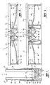
- Figure 2 shows that the first wing, the second wing and the intermediate section are all co-planner when the stage is open and ready for use.
- the material from which the first wing 3, second wing 5 and intermediate section 7 are made can include plywood or like material such as chipboard. Such material may be mounted to a metal peripheral frame for each of the first wing, second wing, and intermediate section 7.
- the metal frame is preferably fabricated from rectangular cross section tubular steel.
- the first wing 3 is swingably supported relative to the intermediate section 7 by hinge means 9 (see Figure 4).
- the hinge means 9 may be any convenient type hinge.
- Figure 1 shows that the first wing 3 and the second wing 5 have been swung upwardly relative to the intermediate section 7 so that the first wing 3 and second wing 5 are substantially parallel to one another and extend upright.
- first retractable metal legs 11 swingably connected with an underside of the first wing 3
- second pair of retractable metal legs 13 swingably connected with an underside of the second wing 5.
- first and second pairs of retractable legs are connected adjacent respective sides of the intermediate section.
- One of the pair of legs 11 is at the front of the stage while the other pair of the legs 11 is at the rear of the stage.
- One of the pair of legs 13 is at the front of the stage while the other of the pair of legs 13 is at the rear of the stage.
- a rectangular shaped metal trolley frame 15 is provided and is attached to the underside of the intermediate sections 7.
- the trolley frame is suitably fastened relative to the intermediate section 7.
- the trolley frame 15 has ground engaging means 17 in the form of castor rollers 17.
- Four such rollers are provided at each of the corners of the trolley frame 15.
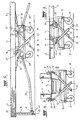
- Figure 7 clearly shows the arrangement.
- Mounted centrally of the trolley frame 15 is a further pair of castor rollers 19 which are larger in diameter than caster rollers of the ground engaging means 17.
- the ground engaging means 17 comprising the castor rollers 17 and 19 can be used for rolling the stage to required positions.
- skids may be provided to permit sliding movement of the stage.
- the trolley frame 15 is provided with guide means 21 in the form of rectangular tube.
- the tube is of steel and suitably welded to the trolley frame 15.
- the guide means 21 are inclined relative to the plane of the intermediate section 7.
- the arrangement is such that the first pair of retractable legs 11 will diagonally cross the second pair of legs 13 underneath the intermediate section 7. Accordingly, feet 23 on each of the legs 11 and 13 (see Figure 4) extend to opposite sides of the intermediate section 7. In other words, the feet 23 of the legs 11 are disposed closer to the side of the intermediate section 7 to which the second wing 5 is swingably attached than the side to which the first wing 3 is attached.
- the feet 23 of the legs 13 are disposed closer to the side of the intermediate section 7 to which the first wing 3 is swingably side than the side to which the second wing 5 is attached. This crossed arrangement provides for rigidity to the structure when the stage is in the open condition.
- the feet 23 of the legs 11 and 13 are below the ground engaging means 17.
- the ground engaging means 17 are elevated relative to a ground surface 25 on which the stage is then supported.
- the feet 23 retract in the guides 21 so that they are above the height of the ground engaging means 17 (as shown in Figure 4) and therefore the stage in the collapsed position, can be readily rolled to required positions.
- the lost motion means 27 comprises an arcuate metal plate with an arcuate slot 29 therein.
- One end of each arcuate plate is swingably connected to the respective frames of the first wing 3 or the second wing 5 by pivot pins 31.
- the uppermost ends of each of the arms 11 and 13 are provided with a respective pin 33 which locates within the respective arcuate slots 29 on the lost motion means 27.
- the pins 33 can be held captive relative to the slots 29 by means of washers and split pins such that the pins 33 cannot displace from the slots 29.
- the arrangement is such that when the respective first wing 3 and second wing 5 are swung to the collapsed position by swinging in an upward direction, the lost motion means 27 allows for the relative swinging motion whilst causing the respective legs 11 and 13 to retract within the respective guides 21 when the pins 33 reach the bottom ends of the arcuate slots 29.
- respective triangular shaped wedges 26 attached to the wings 3 and 5 abut with the top ends of the legs 11 and 13 and push the legs in the guides 21 so the legs 11 and 13 move to the extended positions.
- the wedges 26 firmly bear on the top of the legs 11 and 13 and hold them in the extended position.
- each of the first wing 3 and second wing 5 there are provided further leg means 35.
- These further leg means 35 are preferably of hollow rectangular tube steel.
- the uppermost ends of the further leg means 35 are swingably connected to the respective first wing 3 and second wing 5 by pivot pins 37 (see Figure 5).
- the bottom ends of the further legs 35 are connected with metal link arms 39.
- the link arms 39 are pivotably connected with the further legs 35 by pivot pins 41.
- the opposite ends of the link arms 39 are pivotably connected to the trolley frame 15 by pins 43.
- the link arms 39 cause the further legs 35 to swing about the respective pivot pins 37 so that when the stage is in the closed position, the legs extend substantially parallel with the plane of the respective first wings 3 and second wing 5.
- the link arms 39 cause the respective further legs 35 to assume the upright position shown for example in Figure 5 and 6.
- Each of the further leg means 35 has extendable and retractable metal legs 45.
- Pins 47 can pass through openings in the further legs 35 and legs 45 in 20cm increments of length adjustment of legs 45 relative to further legs 35 to positively hold the legs in the required extended positions.
- the stage can be erected to a first standard height by merely unfolding the first wing and second wing. If the stage is required to be at a higher height from ground surface 25, then the legs 45 can be extended by 20cm as shown for example in Figures 3 and 6.
- auxiliary metal legs 49 can be swung from under the respective first wing 3 and second wing 5.
- each of the auxiliary legs 49 has a somewhat elongated "R" shape.
- the auxiliary legs are, in turn, swingably connected to a frame of each of the first wings 3 and second wing 5 by pivot pins 51.
- the axis of swinging is therefore parallel with the front of the stage and allows the auxiliary arms 49 to swing from a position where they lie generally parallel with the plane of each of the first wing 3 and second wing 5, to a position where they extend generally mutually perpendicular thereto underneath the stage.
- the auxiliary arms 49 may be arranged to swing against a physical stop (not shown) which is slightly over centre relative to the mutually perpendicular extended position. In this case, the auxiliary legs 49 will lock against that stop and provide rigidity to the legs in that extended position.
- the pivot connection through pins 51 is such that considerable force is required to manually swing each of the auxiliary legs 49. This, in turn, holds the legs in the extended position and resting against an adjacent link arm 39.
- Gas strut pistons 53 can be connected to the under surface of the respective first wing 3 and second wing 5 and to the trolley frame 15 by suitable pivot link pins 55.
- the gas strut pistons 53 can be used to provide for controlled swinging movement of the fist wing 3 and second wing 5.
- a handle 55 (see Figure 7 and also Figure 4) may be provided at the outer ends of each of the first wing 3 and second wing 5 to permit easy user handling during swinging.
- the arrangement provides for a stable stage when in the open condition and yet permits easy collapsing of the stage and subsequent transportation.
- the arrangement is such that the opening, installation, subsequent collapsing and removing of the stage can be effected by a single person.
Landscapes
- Engineering & Computer Science (AREA)
- Architecture (AREA)
- Multimedia (AREA)
- Civil Engineering (AREA)
- Structural Engineering (AREA)
- Handcart (AREA)
- Materials For Medical Uses (AREA)
- Road Paving Structures (AREA)
- Manufacture Of Porous Articles, And Recovery And Treatment Of Waste Products (AREA)
Abstract
Description
said intermediate section having ground engaging means thereon to permit rolling or sliding movement of a collapsed stage or like structure,
there being a first pair of retractable legs swingably connected with an underside of said first outer wing adjacent one side of said intermediate section and a second pair of retractable legs swingably connected with an underside of said second outer wing adjacent the otherside of said intermediate section,
guide means attached to said intermediate section guiding each of said retractable legs so that feet means on said legs will be below said ground engaging means when said first and said second outer wings are swung so that they are substantially co-plannar with said intermediate section and will be, above said ground engaging means when said first and said second outer wings are swung upwardly to said collapsed position,
the outermost side regions of said first and said second outer wings each having further leg means swingably connected thereto which can be swung from collapsed positions where they extend substantially parallel to the planes of the respective said first and said second outer wings to erect positions where they extend substantially perpendicular to the planes of the respective said first and said second outer wings.
Claims (5)
- A collapsible stage (1) or like structure having a floor including first plannar and second plannar outer wings (3,5) and an intermediate plannar section (7), said first and said second outer wings (3,5) being swingably connected relative to said intermediate section (7), where they collectively form an open stage (1) or like structure floor, and can be swung therefrom to a collapsed condition where both said first and said second outer wings (3,5) are generally parallel to one another and extend upright,
said intermediate section (7) having ground engaging means (17) thereon to permit rolling or sliding movement when the collapsed stage (1) or like structure is in a collapsed condition,
there being a first pair of retractable legs (11) swingably connected with an underside of said first outer wing (3) adjacent one side of said intermediate section (7) and a second pair of retractable legs (13) swingably connected with an underside of said second outer wing (5) adjacent the otherside of said intermediate section (7),
guide means (21) attached to said intermediate section (7) guiding each of said retractable legs (11,13) so feet (23) of said legs (11,13) will be below said ground engaging means (17) when said first and said second outer wings (3,5) are swung so that they are substantially co-plannar with said intermediate section (7) and will be above said ground engaging means (17) when said first and said second outer wings (3,5) are swung upwardly to said collapsed position,
the outermost side regions of said first and said second outer wings (3,5) each having further leg means (35) swingably connected thereto which can be swung from collapsed positions where they extend substantially parallel to the planes of the respective said first and said second outer wings (3,5) to erect positions where they extend substantially perpendicular to the planes of the respective said first and said second outer wings (3,5), characterised by
said first pair of retractable legs (11) being guided by said guide means (21) so they are always inclined relative to the plane of said intermediate section (7) and so said first pair of retractable legs (11) crosses said second pair of retractable legs (13) underneath said intermediate section (7), so said feet (23) of said first pair are disposed, when extended, to be closer to the side of said intermediate section (7) to which said second outer wing (5) is swingably attached than the side to which said first outer wing (3) attaches, and so said feet (35) of said second pair are disposed, when extended, to be closer to the side of said intermediate section (7) to which said first outer wing (3) is swingably attached than the side to which said second outer wing (5) attaches. - A collapsible stage or like structure as claimed in claim 1 further characterised by a trolley frame (15) connected to the underside of said intermediate section (7), said ground engaging means (17) being connected to said trolley frame (15).
- A collapsible stage or like structure as claimed in claim 2 further characterised in that there is,
link means (39) swingably connected with said further leg means (35) and with said trolley frame (15) which will cause the further leg means (35) to swing to the collapsed positions when said first and said second outer wings (3,5) are swung to the collapsed position and which cause said further leg means (35) to swing to said erect positions when said first and said second outer wings (3,5) are swung to be substantially co-plannar with said intermediate section (7). - A collapsible stage or like structure as claimed in claim 1 further characterised in that there are respective auxiliary legs (49) swingably connected to said first wing (3) and said second wing (5).
- A collapsible stage or like structure as claimed in claim 2 further characterised in that there are respective strut pistons (53) connected to the undersurface of said first wing (3) and said second wing (7) and said trolley frame (15) to provide for controlled swinging of said first wing (3) and said second wing (5).
Applications Claiming Priority (3)
| Application Number | Priority Date | Filing Date | Title |
|---|---|---|---|
| AUPO514597 | 1997-02-18 | ||
| AUPO5145A AUPO514597A0 (en) | 1997-02-18 | 1997-02-18 | A collapsible stage or like structure |
| PCT/AU1998/000097 WO1998037291A1 (en) | 1997-02-18 | 1998-02-17 | A collapsible stage or like structure |
Publications (3)
| Publication Number | Publication Date |
|---|---|
| EP0966586A1 EP0966586A1 (en) | 1999-12-29 |
| EP0966586A4 EP0966586A4 (en) | 2004-03-17 |
| EP0966586B1 true EP0966586B1 (en) | 2005-05-18 |
Family
ID=3799449
Family Applications (1)
| Application Number | Title | Priority Date | Filing Date |
|---|---|---|---|
| EP98902860A Expired - Lifetime EP0966586B1 (en) | 1997-02-18 | 1998-02-17 | A collapsible stage or like structure |
Country Status (7)
| Country | Link |
|---|---|
| US (1) | US6195943B1 (en) |
| EP (1) | EP0966586B1 (en) |
| AT (1) | ATE295922T1 (en) |
| AU (1) | AUPO514597A0 (en) |
| CA (1) | CA2280920C (en) |
| DE (1) | DE69830235T2 (en) |
| WO (1) | WO1998037291A1 (en) |
Families Citing this family (10)
| Publication number | Priority date | Publication date | Assignee | Title |
|---|---|---|---|---|
| US6629581B2 (en) * | 2001-08-29 | 2003-10-07 | The Boeing Company | Maintenance cart for aircraft vehicle |
| USD608459S1 (en) * | 2008-06-10 | 2010-01-19 | Wyse Steven J | Stage deck section |
| US8567811B1 (en) | 2009-02-27 | 2013-10-29 | Garry Jones | Trailer-mounted platform |
| US8418709B2 (en) * | 2009-03-24 | 2013-04-16 | Edar Everyone Deserves A Roof Inc. | Temporary shelter and mobile cart |
| EP2625341B8 (en) * | 2010-10-04 | 2020-10-07 | Parafoil Design & Engineering Pte Ltd | A floodgate |
| USD707365S1 (en) * | 2012-09-15 | 2014-06-17 | Michael James JOHNSTONE | Truck-mounted performance stage |
| CA2901871C (en) | 2013-03-01 | 2016-02-09 | Stageline Scene Mobile Inc. | Articulated floor structure for a mobile stage framework |
| CN110905244B (en) * | 2019-12-09 | 2021-02-05 | 浙江大丰实业股份有限公司 | Lightweight upset stage supporting framework |
| CN112696062A (en) * | 2020-12-17 | 2021-04-23 | 马爱平 | Platform is used in performance form adjustable chorus |
| JP7721125B2 (en) * | 2021-10-21 | 2025-08-12 | 株式会社アルミス | Folding stage |
Family Cites Families (15)
| Publication number | Priority date | Publication date | Assignee | Title |
|---|---|---|---|---|
| US2978754A (en) * | 1959-11-16 | 1961-04-11 | Sico Mfg Co | Portable stage |
| US3152833A (en) * | 1962-04-03 | 1964-10-13 | Catherine B Creveling | Folding table and chair combination |
| US3624782A (en) * | 1969-04-14 | 1971-11-30 | Aircraft Mechanics | Semiautomatic palletizer |
| US3999491A (en) | 1975-12-05 | 1976-12-28 | Wilson Kermit H | Elevationally adjustable folding stage |
| US4054096A (en) | 1976-04-06 | 1977-10-18 | Sico Incorporated | Mobile elevationally adjustable stage |
| US4327650A (en) * | 1979-02-01 | 1982-05-04 | Sico Incorporated | Support structure for mobile folding stage |
| US4643103A (en) * | 1985-03-25 | 1987-02-17 | Jorgensen Robert A | Collapsible table |
| US4779452A (en) | 1986-06-09 | 1988-10-25 | Rockwell International Corporation | High temperature ultrasonic viscometer |
| US4779542A (en) * | 1987-07-31 | 1988-10-25 | Stageright Corporation | Fold and roll staging |
| US4917217A (en) * | 1989-01-23 | 1990-04-17 | Stageright Corporation | Portable folding staging |
| AU659376B2 (en) | 1991-08-09 | 1995-05-11 | Sico Incorporated | Multilevel folding stage |
| US5392718A (en) * | 1992-11-04 | 1995-02-28 | King Arthur Co., Div. Of Shelby Williams Industries, Inc. | Wheel lifting assembly for mobile folding stage unit |
| US5335604A (en) * | 1992-12-15 | 1994-08-09 | Selby Furniture Hardware Company, Inc. | Folding table |
| DE69505101T2 (en) * | 1994-01-10 | 1999-02-25 | Sico Inc., Minneapolis, Minn. | ROLLER DEVICE WITH LIFTING MECHANISM |
| US5613450A (en) * | 1994-11-10 | 1997-03-25 | Sico Incorporated | Mobile folding stage |
-
1997
- 1997-02-18 AU AUPO5145A patent/AUPO514597A0/en not_active Abandoned
-
1998
- 1998-02-17 DE DE69830235T patent/DE69830235T2/en not_active Expired - Lifetime
- 1998-02-17 WO PCT/AU1998/000097 patent/WO1998037291A1/en not_active Ceased
- 1998-02-17 US US09/367,279 patent/US6195943B1/en not_active Expired - Lifetime
- 1998-02-17 CA CA002280920A patent/CA2280920C/en not_active Expired - Lifetime
- 1998-02-17 AT AT98902860T patent/ATE295922T1/en not_active IP Right Cessation
- 1998-02-17 EP EP98902860A patent/EP0966586B1/en not_active Expired - Lifetime
Also Published As
| Publication number | Publication date |
|---|---|
| DE69830235T2 (en) | 2006-01-26 |
| CA2280920A1 (en) | 1998-08-27 |
| DE69830235D1 (en) | 2005-06-23 |
| US6195943B1 (en) | 2001-03-06 |
| CA2280920C (en) | 2006-01-24 |
| ATE295922T1 (en) | 2005-06-15 |
| AUPO514597A0 (en) | 1997-04-11 |
| WO1998037291A1 (en) | 1998-08-27 |
| EP0966586A4 (en) | 2004-03-17 |
| EP0966586A1 (en) | 1999-12-29 |
Similar Documents
| Publication | Publication Date | Title |
|---|---|---|
| CA1303640C (en) | Fold and roll staging | |
| US5325640A (en) | Folding stage system | |
| US4630627A (en) | Collapsible frame structure | |
| US4284286A (en) | Combination handtruck and portable work table | |
| US5003652A (en) | Collapsible hammock | |
| US6454282B2 (en) | Cart for folding tables | |
| AU741452B2 (en) | Folding stage | |
| US6195943B1 (en) | Collapsible stage or like structure | |
| US6192809B1 (en) | Collapsible folding massage table | |
| US3999491A (en) | Elevationally adjustable folding stage | |
| EP1303436B1 (en) | Wheeled platform for erectable canopy shelter | |
| US4240646A (en) | Combined drum-set carrier and performance platform | |
| US7500335B1 (en) | Portable deck for recreational vehicles and fifth wheel campers | |
| US7584575B2 (en) | Variable height fold and roll staging and method of assembling same | |
| US5839538A (en) | Foldable portable tree stand | |
| US7089610B2 (en) | Portable hammock | |
| CN1119481C (en) | Folding stage | |
| US4801117A (en) | Portable support boom for window washer | |
| EP0515578A1 (en) | Improvements to palletization platforms | |
| AU724609B2 (en) | A collapsible stage or like structure | |
| JPH05507977A (en) | arched structure | |
| KR102209909B1 (en) | Carrying cart with table function | |
| US3515243A (en) | Lift device | |
| US7128001B2 (en) | Foldable table | |
| CN220769345U (en) | Retractable and foldable guardrail ladder |
Legal Events
| Date | Code | Title | Description |
|---|---|---|---|
| PUAI | Public reference made under article 153(3) epc to a published international application that has entered the european phase |
Free format text: ORIGINAL CODE: 0009012 |
|
| 17P | Request for examination filed |
Effective date: 19990812 |
|
| AK | Designated contracting states |
Kind code of ref document: A1 Designated state(s): AT BE CH DE DK ES FI FR GB GR IE IT LI LU MC NL PT SE |
|
| A4 | Supplementary search report drawn up and despatched |
Effective date: 20040129 |
|
| GRAP | Despatch of communication of intention to grant a patent |
Free format text: ORIGINAL CODE: EPIDOSNIGR1 |
|
| GRAS | Grant fee paid |
Free format text: ORIGINAL CODE: EPIDOSNIGR3 |
|
| GRAA | (expected) grant |
Free format text: ORIGINAL CODE: 0009210 |
|
| AK | Designated contracting states |
Kind code of ref document: B1 Designated state(s): AT BE CH DE DK ES FI FR GB GR IE IT LI LU MC NL PT SE |
|
| PG25 | Lapsed in a contracting state [announced via postgrant information from national office to epo] |
Ref country code: NL Free format text: LAPSE BECAUSE OF FAILURE TO SUBMIT A TRANSLATION OF THE DESCRIPTION OR TO PAY THE FEE WITHIN THE PRESCRIBED TIME-LIMIT Effective date: 20050518 Ref country code: LI Free format text: LAPSE BECAUSE OF FAILURE TO SUBMIT A TRANSLATION OF THE DESCRIPTION OR TO PAY THE FEE WITHIN THE PRESCRIBED TIME-LIMIT Effective date: 20050518 Ref country code: FI Free format text: LAPSE BECAUSE OF FAILURE TO SUBMIT A TRANSLATION OF THE DESCRIPTION OR TO PAY THE FEE WITHIN THE PRESCRIBED TIME-LIMIT Effective date: 20050518 Ref country code: CH Free format text: LAPSE BECAUSE OF FAILURE TO SUBMIT A TRANSLATION OF THE DESCRIPTION OR TO PAY THE FEE WITHIN THE PRESCRIBED TIME-LIMIT Effective date: 20050518 Ref country code: BE Free format text: LAPSE BECAUSE OF FAILURE TO SUBMIT A TRANSLATION OF THE DESCRIPTION OR TO PAY THE FEE WITHIN THE PRESCRIBED TIME-LIMIT Effective date: 20050518 Ref country code: AT Free format text: LAPSE BECAUSE OF FAILURE TO SUBMIT A TRANSLATION OF THE DESCRIPTION OR TO PAY THE FEE WITHIN THE PRESCRIBED TIME-LIMIT Effective date: 20050518 |
|
| REG | Reference to a national code |
Ref country code: GB Ref legal event code: FG4D |
|
| REG | Reference to a national code |
Ref country code: CH Ref legal event code: EP |
|
| REG | Reference to a national code |
Ref country code: IE Ref legal event code: FG4D |
|
| REF | Corresponds to: |
Ref document number: 69830235 Country of ref document: DE Date of ref document: 20050623 Kind code of ref document: P |
|
| PG25 | Lapsed in a contracting state [announced via postgrant information from national office to epo] |
Ref country code: SE Free format text: LAPSE BECAUSE OF FAILURE TO SUBMIT A TRANSLATION OF THE DESCRIPTION OR TO PAY THE FEE WITHIN THE PRESCRIBED TIME-LIMIT Effective date: 20050818 Ref country code: GR Free format text: LAPSE BECAUSE OF FAILURE TO SUBMIT A TRANSLATION OF THE DESCRIPTION OR TO PAY THE FEE WITHIN THE PRESCRIBED TIME-LIMIT Effective date: 20050818 Ref country code: DK Free format text: LAPSE BECAUSE OF FAILURE TO SUBMIT A TRANSLATION OF THE DESCRIPTION OR TO PAY THE FEE WITHIN THE PRESCRIBED TIME-LIMIT Effective date: 20050818 |
|
| PG25 | Lapsed in a contracting state [announced via postgrant information from national office to epo] |
Ref country code: PT Free format text: LAPSE BECAUSE OF FAILURE TO SUBMIT A TRANSLATION OF THE DESCRIPTION OR TO PAY THE FEE WITHIN THE PRESCRIBED TIME-LIMIT Effective date: 20051024 |
|
| REG | Reference to a national code |
Ref country code: CH Ref legal event code: PL |
|
| NLV1 | Nl: lapsed or annulled due to failure to fulfill the requirements of art. 29p and 29m of the patents act | ||
| PG25 | Lapsed in a contracting state [announced via postgrant information from national office to epo] |
Ref country code: IE Free format text: LAPSE BECAUSE OF NON-PAYMENT OF DUE FEES Effective date: 20060217 |
|
| PG25 | Lapsed in a contracting state [announced via postgrant information from national office to epo] |
Ref country code: MC Free format text: LAPSE BECAUSE OF NON-PAYMENT OF DUE FEES Effective date: 20060228 Ref country code: LU Free format text: LAPSE BECAUSE OF NON-PAYMENT OF DUE FEES Effective date: 20060228 |
|
| PLBE | No opposition filed within time limit |
Free format text: ORIGINAL CODE: 0009261 |
|
| STAA | Information on the status of an ep patent application or granted ep patent |
Free format text: STATUS: NO OPPOSITION FILED WITHIN TIME LIMIT |
|
| ET | Fr: translation filed | ||
| 26N | No opposition filed |
Effective date: 20060221 |
|
| REG | Reference to a national code |
Ref country code: IE Ref legal event code: MM4A |
|
| PG25 | Lapsed in a contracting state [announced via postgrant information from national office to epo] |
Ref country code: ES Free format text: LAPSE BECAUSE OF NON-PAYMENT OF DUE FEES Effective date: 20060228 |
|
| PGFP | Annual fee paid to national office [announced via postgrant information from national office to epo] |
Ref country code: FR Payment date: 20110315 Year of fee payment: 14 Ref country code: IT Payment date: 20110225 Year of fee payment: 14 Ref country code: DE Payment date: 20110216 Year of fee payment: 14 |
|
| PGFP | Annual fee paid to national office [announced via postgrant information from national office to epo] |
Ref country code: GB Payment date: 20110216 Year of fee payment: 14 |
|
| GBPC | Gb: european patent ceased through non-payment of renewal fee |
Effective date: 20120217 |
|
| REG | Reference to a national code |
Ref country code: FR Ref legal event code: ST Effective date: 20121031 |
|
| PG25 | Lapsed in a contracting state [announced via postgrant information from national office to epo] |
Ref country code: IT Free format text: LAPSE BECAUSE OF NON-PAYMENT OF DUE FEES Effective date: 20120217 |
|
| REG | Reference to a national code |
Ref country code: DE Ref legal event code: R119 Ref document number: 69830235 Country of ref document: DE Effective date: 20120901 |
|
| PG25 | Lapsed in a contracting state [announced via postgrant information from national office to epo] |
Ref country code: FR Free format text: LAPSE BECAUSE OF NON-PAYMENT OF DUE FEES Effective date: 20120229 Ref country code: GB Free format text: LAPSE BECAUSE OF NON-PAYMENT OF DUE FEES Effective date: 20120217 |
|
| PG25 | Lapsed in a contracting state [announced via postgrant information from national office to epo] |
Ref country code: DE Free format text: LAPSE BECAUSE OF NON-PAYMENT OF DUE FEES Effective date: 20120901 |