EP0966198B1 - Extruder and die assembly for extruding shaped food pieces - Google Patents
Extruder and die assembly for extruding shaped food pieces Download PDFInfo
- Publication number
- EP0966198B1 EP0966198B1 EP98906565A EP98906565A EP0966198B1 EP 0966198 B1 EP0966198 B1 EP 0966198B1 EP 98906565 A EP98906565 A EP 98906565A EP 98906565 A EP98906565 A EP 98906565A EP 0966198 B1 EP0966198 B1 EP 0966198B1
- Authority
- EP
- European Patent Office
- Prior art keywords
- die
- extrusion
- cutter
- wall
- tubular
- Prior art date
- Legal status (The legal status is an assumption and is not a legal conclusion. Google has not performed a legal analysis and makes no representation as to the accuracy of the status listed.)
- Expired - Lifetime
Links
- 235000013305 food Nutrition 0.000 title claims description 75
- 238000001125 extrusion Methods 0.000 claims description 109
- 239000012530 fluid Substances 0.000 claims description 15
- 238000004891 communication Methods 0.000 claims description 14
- 239000000463 material Substances 0.000 claims description 7
- 229920003023 plastic Polymers 0.000 claims description 5
- 239000004033 plastic Substances 0.000 claims description 5
- 229920006351 engineering plastic Polymers 0.000 claims description 3
- 235000006085 Vigna mungo var mungo Nutrition 0.000 description 79
- 240000005616 Vigna mungo var. mungo Species 0.000 description 79
- 241000238557 Decapoda Species 0.000 description 19
- 238000000034 method Methods 0.000 description 10
- 241000287828 Gallus gallus Species 0.000 description 8
- 230000008569 process Effects 0.000 description 8
- 230000000712 assembly Effects 0.000 description 7
- 238000000429 assembly Methods 0.000 description 7
- 244000061456 Solanum tuberosum Species 0.000 description 6
- 235000002595 Solanum tuberosum Nutrition 0.000 description 6
- 238000006073 displacement reaction Methods 0.000 description 6
- 230000003134 recirculating effect Effects 0.000 description 6
- 230000008901 benefit Effects 0.000 description 5
- 239000003349 gelling agent Substances 0.000 description 5
- 238000012545 processing Methods 0.000 description 5
- 235000013410 fast food Nutrition 0.000 description 4
- 238000010438 heat treatment Methods 0.000 description 4
- 239000007788 liquid Substances 0.000 description 4
- 235000012015 potatoes Nutrition 0.000 description 4
- 230000009471 action Effects 0.000 description 3
- 238000013459 approach Methods 0.000 description 3
- 238000001816 cooling Methods 0.000 description 3
- 239000002245 particle Substances 0.000 description 3
- XLYOFNOQVPJJNP-UHFFFAOYSA-N water Substances O XLYOFNOQVPJJNP-UHFFFAOYSA-N 0.000 description 3
- 229920002230 Pectic acid Polymers 0.000 description 2
- AEMOLEFTQBMNLQ-BKBMJHBISA-N alpha-D-galacturonic acid Chemical compound O[C@H]1O[C@H](C(O)=O)[C@H](O)[C@H](O)[C@H]1O AEMOLEFTQBMNLQ-BKBMJHBISA-N 0.000 description 2
- 239000000796 flavoring agent Substances 0.000 description 2
- 235000019634 flavors Nutrition 0.000 description 2
- 238000007710 freezing Methods 0.000 description 2
- 230000008014 freezing Effects 0.000 description 2
- 230000006872 improvement Effects 0.000 description 2
- 230000014759 maintenance of location Effects 0.000 description 2
- 230000004048 modification Effects 0.000 description 2
- 238000012986 modification Methods 0.000 description 2
- 210000002445 nipple Anatomy 0.000 description 2
- 239000003755 preservative agent Substances 0.000 description 2
- 238000003303 reheating Methods 0.000 description 2
- 239000007787 solid Substances 0.000 description 2
- IXPNQXFRVYWDDI-UHFFFAOYSA-N 1-methyl-2,4-dioxo-1,3-diazinane-5-carboximidamide Chemical compound CN1CC(C(N)=N)C(=O)NC1=O IXPNQXFRVYWDDI-UHFFFAOYSA-N 0.000 description 1
- UXVMQQNJUSDDNG-UHFFFAOYSA-L Calcium chloride Chemical compound [Cl-].[Cl-].[Ca+2] UXVMQQNJUSDDNG-UHFFFAOYSA-L 0.000 description 1
- 241000117167 Caprella linearis Species 0.000 description 1
- 229920002907 Guar gum Polymers 0.000 description 1
- 244000141359 Malus pumila Species 0.000 description 1
- 240000007594 Oryza sativa Species 0.000 description 1
- 235000007164 Oryza sativa Nutrition 0.000 description 1
- 229920002472 Starch Polymers 0.000 description 1
- 229910000831 Steel Inorganic materials 0.000 description 1
- 235000021307 Triticum Nutrition 0.000 description 1
- 244000098338 Triticum aestivum Species 0.000 description 1
- 240000008042 Zea mays Species 0.000 description 1
- 235000005824 Zea mays ssp. parviglumis Nutrition 0.000 description 1
- 235000002017 Zea mays subsp mays Nutrition 0.000 description 1
- 238000005299 abrasion Methods 0.000 description 1
- 230000006978 adaptation Effects 0.000 description 1
- 239000003963 antioxidant agent Substances 0.000 description 1
- 235000021016 apples Nutrition 0.000 description 1
- 235000015278 beef Nutrition 0.000 description 1
- 239000011230 binding agent Substances 0.000 description 1
- 210000000988 bone and bone Anatomy 0.000 description 1
- 239000001110 calcium chloride Substances 0.000 description 1
- 229910001628 calcium chloride Inorganic materials 0.000 description 1
- 239000004464 cereal grain Substances 0.000 description 1
- 235000013339 cereals Nutrition 0.000 description 1
- 230000008859 change Effects 0.000 description 1
- 235000013351 cheese Nutrition 0.000 description 1
- 239000003795 chemical substances by application Substances 0.000 description 1
- 239000003086 colorant Substances 0.000 description 1
- 210000002808 connective tissue Anatomy 0.000 description 1
- 238000010411 cooking Methods 0.000 description 1
- 235000005822 corn Nutrition 0.000 description 1
- 235000013365 dairy product Nutrition 0.000 description 1
- 230000003247 decreasing effect Effects 0.000 description 1
- 235000012489 doughnuts Nutrition 0.000 description 1
- 235000013399 edible fruits Nutrition 0.000 description 1
- 230000000694 effects Effects 0.000 description 1
- 238000005516 engineering process Methods 0.000 description 1
- -1 for example Polymers 0.000 description 1
- 235000010417 guar gum Nutrition 0.000 description 1
- 239000000665 guar gum Substances 0.000 description 1
- 229960002154 guar gum Drugs 0.000 description 1
- 235000021182 hors d'oeuvre Nutrition 0.000 description 1
- 239000004615 ingredient Substances 0.000 description 1
- 235000012054 meals Nutrition 0.000 description 1
- 235000013372 meat Nutrition 0.000 description 1
- 238000004806 packaging method and process Methods 0.000 description 1
- 238000009928 pasteurization Methods 0.000 description 1
- 244000144977 poultry Species 0.000 description 1
- 235000013594 poultry meat Nutrition 0.000 description 1
- 238000003908 quality control method Methods 0.000 description 1
- 235000021067 refined food Nutrition 0.000 description 1
- 235000009566 rice Nutrition 0.000 description 1
- 235000014102 seafood Nutrition 0.000 description 1
- 238000007493 shaping process Methods 0.000 description 1
- 235000011888 snacks Nutrition 0.000 description 1
- 235000010413 sodium alginate Nutrition 0.000 description 1
- 239000000661 sodium alginate Substances 0.000 description 1
- 229940005550 sodium alginate Drugs 0.000 description 1
- 239000007921 spray Substances 0.000 description 1
- 238000005507 spraying Methods 0.000 description 1
- 239000003381 stabilizer Substances 0.000 description 1
- 235000019698 starch Nutrition 0.000 description 1
- 239000008107 starch Substances 0.000 description 1
- 239000010959 steel Substances 0.000 description 1
- 230000002459 sustained effect Effects 0.000 description 1
- 235000013311 vegetables Nutrition 0.000 description 1
- 235000019682 ‘finger’ food Nutrition 0.000 description 1
Images
Classifications
-
- A—HUMAN NECESSITIES
- A21—BAKING; EDIBLE DOUGHS
- A21C—MACHINES OR EQUIPMENT FOR MAKING OR PROCESSING DOUGHS; HANDLING BAKED ARTICLES MADE FROM DOUGH
- A21C11/00—Other machines for forming the dough into its final shape before cooking or baking
- A21C11/16—Extruding machines
-
- B—PERFORMING OPERATIONS; TRANSPORTING
- B29—WORKING OF PLASTICS; WORKING OF SUBSTANCES IN A PLASTIC STATE IN GENERAL
- B29C—SHAPING OR JOINING OF PLASTICS; SHAPING OF MATERIAL IN A PLASTIC STATE, NOT OTHERWISE PROVIDED FOR; AFTER-TREATMENT OF THE SHAPED PRODUCTS, e.g. REPAIRING
- B29C48/00—Extrusion moulding, i.e. expressing the moulding material through a die or nozzle which imparts the desired form; Apparatus therefor
- B29C48/001—Combinations of extrusion moulding with other shaping operations
- B29C48/0022—Combinations of extrusion moulding with other shaping operations combined with cutting
-
- B—PERFORMING OPERATIONS; TRANSPORTING
- B29—WORKING OF PLASTICS; WORKING OF SUBSTANCES IN A PLASTIC STATE IN GENERAL
- B29C—SHAPING OR JOINING OF PLASTICS; SHAPING OF MATERIAL IN A PLASTIC STATE, NOT OTHERWISE PROVIDED FOR; AFTER-TREATMENT OF THE SHAPED PRODUCTS, e.g. REPAIRING
- B29C48/00—Extrusion moulding, i.e. expressing the moulding material through a die or nozzle which imparts the desired form; Apparatus therefor
- B29C48/022—Extrusion moulding, i.e. expressing the moulding material through a die or nozzle which imparts the desired form; Apparatus therefor characterised by the choice of material
-
- B—PERFORMING OPERATIONS; TRANSPORTING
- B29—WORKING OF PLASTICS; WORKING OF SUBSTANCES IN A PLASTIC STATE IN GENERAL
- B29C—SHAPING OR JOINING OF PLASTICS; SHAPING OF MATERIAL IN A PLASTIC STATE, NOT OTHERWISE PROVIDED FOR; AFTER-TREATMENT OF THE SHAPED PRODUCTS, e.g. REPAIRING
- B29C48/00—Extrusion moulding, i.e. expressing the moulding material through a die or nozzle which imparts the desired form; Apparatus therefor
- B29C48/03—Extrusion moulding, i.e. expressing the moulding material through a die or nozzle which imparts the desired form; Apparatus therefor characterised by the shape of the extruded material at extrusion
- B29C48/131—Curved articles
-
- B—PERFORMING OPERATIONS; TRANSPORTING
- B29—WORKING OF PLASTICS; WORKING OF SUBSTANCES IN A PLASTIC STATE IN GENERAL
- B29C—SHAPING OR JOINING OF PLASTICS; SHAPING OF MATERIAL IN A PLASTIC STATE, NOT OTHERWISE PROVIDED FOR; AFTER-TREATMENT OF THE SHAPED PRODUCTS, e.g. REPAIRING
- B29C48/00—Extrusion moulding, i.e. expressing the moulding material through a die or nozzle which imparts the desired form; Apparatus therefor
- B29C48/25—Component parts, details or accessories; Auxiliary operations
- B29C48/30—Extrusion nozzles or dies
- B29C48/345—Extrusion nozzles comprising two or more adjacently arranged ports, for simultaneously extruding multiple strands, e.g. for pelletising
-
- B—PERFORMING OPERATIONS; TRANSPORTING
- B29—WORKING OF PLASTICS; WORKING OF SUBSTANCES IN A PLASTIC STATE IN GENERAL
- B29C—SHAPING OR JOINING OF PLASTICS; SHAPING OF MATERIAL IN A PLASTIC STATE, NOT OTHERWISE PROVIDED FOR; AFTER-TREATMENT OF THE SHAPED PRODUCTS, e.g. REPAIRING
- B29C48/00—Extrusion moulding, i.e. expressing the moulding material through a die or nozzle which imparts the desired form; Apparatus therefor
- B29C48/25—Component parts, details or accessories; Auxiliary operations
- B29C48/36—Means for plasticising or homogenising the moulding material or forcing it through the nozzle or die
- B29C48/475—Means for plasticising or homogenising the moulding material or forcing it through the nozzle or die using pistons, accumulators or press rams
Definitions
- the present invention relates to an extruder and a die and cutter assembly for producing an extruded food piece which simulates the shape of a natural food piece comprising the features of the preamble of claim 1, respectively claim 2.
- Such an extruder, respectively die and cutter assembly is disclosed in US-A- 4 080 137.
- the piece may be a part of a natural food or the entire natural food may constitute the piece itself.
- deep-fried shrimp the entire natural food
- deep-fried chicken is eaten as a piece of that natural food, e.g. a drumstick.
- the piece may be constituted by some designed subdivision of the natural food, such as cut strips of potato for preparing French fried potatoes. Irrespective of the origin of the piece, whether the entire natural food or a part of the natural food, it is expected by the consumer that the characteristic shape of that piece be present in the food to be consumed, and this expectation is very important to the satisfaction of the consumer. For example, while a potato may be cut into shapes significantly different from the traditional strips of French fried potatoes, if those shapes differ substantially from the traditional strips, the consumer would likely not consider that food French fried potatoes and would object to such shapes.
- natural shrimp can vary considerably in size and, hence, causes variations in the processing of the deep-fried shrimp for institutional, fast food and prepackaged purposes.
- this causes difficulty in the finished cooking of those foods, since the natural variation in size causes differences in the initial requirements of processing prior to packaging (including freezing) and in the time required for reheating for finish frying, e.g. in a microwave oven or deep-fat frying.
- This method of processing food into an extruded shape is also used for convenience purposes, especially in snack foods.
- chicken can be so processed through the mash and extruding steps to produce a miniature chicken drumstick, which, of course, has no bone, connective tissue and the like and is, therefore, quite useful as a finger food, such as hors d'oeuvres, light meals and the like.
- the prior art extruding processes involve grinding the food to an appropriate particle size, e.g. to pass through a U. S. Screen Series No. 10 screen, forming that ground food into a mash, usually with added water and gelling agents, and optionally formulated with other ingredients such as starch, cereals, flavors, preservatives, etc., and placing that mash in a pressure vessel which feeds a manifold upon which one or more die and cutter assemblies are mounted.
- the die and cutter assembly basically, is comprised of an inner sleeve (also referred to in the art as a nozzle) in fluid communication with the manifold through which the mash passes and an outer sleeve which is reciprocated relative to that inner sleeve for cutting extrudate into shaped pieces as the extrudate passes through a die in that inner sleeve.
- an inner sleeve also referred to in the art as a nozzle
- the die was at the end of the inner sleeve and a cutter cooperated with that die for cutting extrudate into pieces as the mash passed through the die.
- this earlier arrangement has little ability to form shapes which accurately simulate the shape of a natural food piece, and, as a result, the art moved toward the more modern die and cutter arrangement.
- U. S. Patent 2,676,552 issued on April 27, 1954, shows the generally modern arrangement of such die and cutter assemblies.
- an inner sleeve forms a conduit for the mash and an outer sleeve forms the cutter for cutting the extrudate (mash) into individual pieces, but at the end of the inner sleeve, a disk is disposed so that the die so formed is circular in configuration and can, therefore, extrude and cut a shape in the form of doughnut.
- the outer sleeve is reciprocated on the inner sleeve by contact with shoulders on the inner sleeve which form bearing surfaces for the reciprocal motion of the outer sleeve.
- That apparatus entails a pressure vessel for containing the ground mash of the food.
- Pressure is exerted in the pressure vessel by a pressure exerting device which can be any device to exert pressure on the mash, e.g. overhead gaseous pressure, pump pressure, mechanical pressure, e.g. a piston, and the like, and no particular form of pressure exerting device is required.
- a manifold is in fluid communication with the pressure vessel and at least one, but usually a number of, die and cutter assemblies are in fluid communication with the manifold, such that the pressurized mash in the pressure vessel flows through the manifold and into the die and cutter assemblies.
- Each die and cutter assembly has an elongated, annular tubular member with a tubular extrusion wall (essentially the inner sleeve of the prior art, as noted above), a closed extrusion end, an opened feed end attachable in fluid communication to the manifold, at least one extrusion die formed in the tubular extrusion wall near the extrusion end (essentially the side wall of the inner sleeve of the prior art), a tubular cutter having an opened driveable end, and an elongated cutter wall with an opened cutter end with at least one cutting surface for cutting the extrudate into the shape as the extrudate exits the die.
- That cutter is disposed at least partially over and reciprocally slideable on the tubular extrusion wall (essentially the same as the inner sleeve of the prior art) and operably connected at the driveable end to a drive device for reciprocally sliding the cutter member over and away from the die.
- the drive device can be any device for reciprocably moving the cutter member, e.g. mechanical, electrical, and fluid-operated devices. This arrangement is particularly shown in U. S. Patent 4,080,137, noted above, and the conditions and parameters of such apparatus are well known in the art and need not be repeated herein.
- the extrusion die of the prior art must have a shape generally configured to a cross-sectional shape of the natural food piece to be extruded, but which die must also be configured so as to provide a substantially constant transverse flow rate of the mash through the die at substantially all portions of the die.
- the extruded piece could, nonetheless, closely simulate the shape of the natural food piece, while at the same time providing a substantially constant transverse flow rate of the mash through the die at substantially all portions of the die.
- the extruded piece simulates the shape of a natural food piece, while at the same time provides that the extruded piece has the rounded shape of the natural piece and not the prior art distorted shape.
- the cutter member must be reciprocated at speeds sufficient that the cutter member is disposed over the die for a time period that the pressure of the mash in the tubular extrusion wall is not substantially changed during a reciprocation of the cutter member. This is achieved by arranging the drive device and/or the die and cutter assembly so that such reciprocation of the cutter member is provided.
- the cutting surface of the cutter member must be generally configured to a shape which is substantially the shape of at least the first one-quarter of the die first encountered by the cutting surface when cutting a food piece.
- Other shapes such as the generally flat cutting surface of the prior art, when encountering the first portion of the die in a reciprocal action, cut too much of the extrudate near that first encountered portion before remaining portions of the extrudate are cut. This caused a distortion in the shape of the extrudate.
- the cutting surface by configuring the cutting surface to a shape which is substantially the shape of at least the first one-quarter of the die first countered by the cutting surface, a significantly greater amount of extrudate is cut at the same time, and this avoids that distortion in the extruded and cut shape.
- the present invention is an improvement in an extruder for producing an extruded food piece in a shape which simulates the shape of a natural food piece.
- Such conventional extruders comprise a pressure vessel for containing a mash of the food under pressure, a pressure exerting device for maintaining a pressure in the pressure vessel, a manifold in fluid communication with the pressure vessel, and at least one die and cutter assembly in fluid communication with the manifold.
- the die and cutter assembly has (a) an elongated annular extrusion member with a tubular extrusion wall, (b) a closed extrusion end, (c) an opened feed end attached in fluid communication to the manifold, (d) at least one extrusion die formed in the tubular extrusion wall near the extrusion end and having an axially curved edge, and (e) a tubular cutter member having an opened driveable end, an elongated cutter wall and an opened cutter end with at least one cutting surface for cutting extrudate into the shape as the extrudate exits the die.
- the cutter member is disposed at least partially over and reciprocally slideable on the tubular extrusion wall and operably connected at the driveable end to a drive device for reciprocally sliding the cutter member over and away from the die.
- the present improvement in that known extruder is where the curved edge of the extrusion die is generally configured to a cross-sectional shape of the natural food piece but which die is also configured so as to provide a substantially constant transverse flow rate of the mash through the die at substantially all portions of the die, the drive device is arranged to reciprocate the cutter member at speeds sufficient that the cutter member is disposed over the die for a time period such that a pressure of the mash in the tubular extrusion wall is not substantially changed during a reciprocation of the cutter member, and the cutting surface shape is generally approximating the shape of the at least first one-quarter of the die first encountered by the cutting surface when cutting a food piece.
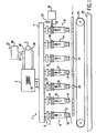
- the extruder As shown in Figure 1, the extruder, generally 1, has a pressure vessel 2, a pressure exerting device 3 for maintaining a pressure on the pressure vessel 2, a manifold 4 in fluid communication (conduit 5) with the pressure vessel 2. There is at least one die and cutter assembly 6 (seven being shown in Figure 1). It will be noted that the die and cutter assembly 6 is in fluid communication with the manifold 4 by way of an attachment 7 to a nipple 8 of the manifold.
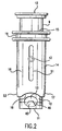
- a die and cutter assembly 6 is best understood from both Figures 1 and 2.
- a die and cutter assembly has an elongated annular extrusion member 9 with a tubular extrusion wall 10, a closed extrusion end 11, and an open feed end 12 attached in fluid communication, e.g. by nipple 8, to manifold 4.
- a tubular cutter member 14 has an opened driveable end 15, an elongated cutter wall 16 and an opened cutter end 17 with at least one cutting surface 18 for cutting extrudate into a shape as the extrudate exits the die 13.
- the cutter member 14 is disposed at least partially over and reciprocally slideable on the tubular extrusion wall 10 and operably connected at a drive end 19 to a drive device 20 (see Figure 1) for reciprocally sliding, as indicated by arrows 21, the cutter member 14 over and away from die 13.
- the cutter wall 16 is so reciprocated by a drive device, e.g. a drive arm 22, and details of such a drive arm may be found in U. S. Patent 4,080,137.
- a gelling agent may be sprayed onto the cut extrudate as it drops to conveyor 23 by passing through a spray of liquid gelling agent produced by a series of sprayers 24 intermediate the die 13 and the conveyor 23. Excess spraying agent is caught by a trough 25.
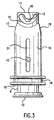
- the present invention centers around the die and cutter assembly 6, although not exclusively, and an embodiment of the invention is shown in Figures 3 through 5, although similar parts of the die and cutter assembly are also shown in Figures 1 and 2.
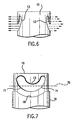
- the extrusion die 13 of the present invention has a shape generally configured to a cross-sectional shape of a natural food piece, and in the embodiment illustrated in Figure 3, the shape is that of a natural fried shrimp.
- the die in addition to having the general shape of that natural food piece, e.g. the fried shrimp, the die must also be configured so as to provide a substantially constant transverse flow rate of the mash through the die at substantially all portions of the die.
- the cross-sectional shape of the die requires some experimentation, and, generally, the cross-sectional shape of the die will not vary greatly from the cross-sectional shape of the natural food piece.
- the cross-sectional shape of the die fairly closely approximates the cross-sectional shape of the natural food piece being extruded, i.e. a fried shrimp.
- deviations from that true cross-sectional shape will be required to ensure the substantially constant flow rate of mash through the die at substantially all portions of the die.
- the flow rate of the mash through the die will depend on the pressure of the mash in tubular extrusion wall 10.
- the pressure of the mash in tubular extrusion wall 10 will depend upon the pressure of the mash in pressure vessel 2, the pressure of the mash in manifold 4, and the flow rate through all of these.
- Figure 1 if all of the dies 13 are open at the same time, a considerable amount of mash would extrude therethrough and the pressure in each tubular extrusion wall 10 would quickly drop. Further, as the mash exits die 13 (see Figures 2 and 6), there will be a local pressure drop at the die 13.
- the drive device 20 (see Figure 1) must be arranged to reciprocate the cutter member 14 at speeds sufficient that the cutter member 14 is disposed over the die for a period of time that the pressure of the mash in the tubular extrusion wall 10 is not substantially changed during a reciprocation of the cutter member.
- the cutter member 14 By so reciprocating the cutter member 14, excess pressure does not build in tubular extrusion wall 10 and, at the same time, by so reciprocating the cutter member 14, the die is open for extrusion for such a time that a local pressure drop of the mash at the die does not substantially occur.
- the cutting surface 18 (see Figures 2 and 5) is generally configured to a shape which is substantially the shape of the at least first one-quarter of the die 13 first encountered by the cutting surface 18 when cutting the extrudate into a food piece.
- Figure 7 illustrates this feature where the die 13 in extrusion wall 10 has indicated thereon a dashed line 70 which approximates the first one-quarter of the die first encountered by the cutting surface 18 of cutter wall 16.
- the cutter surface 18 is generally configured to a shape which is substantially the shape of that at least first one-quarter of the die 13 encountered by the cutter surface 18 when cutting the extrudate into a food piece.
- the cutting surface By so configuring the cutting surface to that at least first one-quarter of the die shape, it can be ensured that, as the cutting of the extrudate commences, the cutting takes place over a large portion of the lowermost part 71 of the die and that the cutting commences over a wider area of that lowermost part, i.e. at least the first one-quarter thereof.
- This is opposed to a flat cutter surface 18 which was used in the prior art or even a somewhat slightly curved cutting surface 18 (see Figure 2) which has also been known.
- the configured cutting surface 18 it is preferable that more than at least the first one-quarter of the die is contacted by the configured cutting surface 18, e.g. one-third or even one-half, but this is not always practical for all shapes that may be desired with extrusion die 13. Nevertheless, if at least the first one-quarter of the die encountered by the cutting surface 18 is generally configured to that shape, this will be sufficient to produce a cut extrudate closely simulating the shape of a natural food piece, especially when practiced with the substantially constant flow rate of the mash through the die at substantially all portions of the die, and the reciprocation of the cutter member, as explained above.
- the substantially constant flow rate will, in part, depend on maintaining a substantially constant pressure in the pressure vessel 2, which pressure is provided by a pressure exerting device 3 (see Figure 1). While that pressure exerting device might be any device, e.g. a gas pressure such as compressed air or the like, it is preferred that the pressure exerting device 3 is a pump in recirculating conduit 26 (see Figure 1) for continuously recirculating the mash from pressure vessel 2 through pump 3 and back into pressure vessel 2 so as to maintain a constant pressure of the mash in pressure vessel 2. When the pump is disposed in a recirculating conduit for the pressure vessel, that pressure can be very carefully and consistently controlled. This is especially true where the pump is a positive displacement pump, which is the preferred embodiment of the invention.
- the cutter member 14 should be reciprocated over the die 13 at a rate of between about 60 and 800 cycles per minute, and more preferable at a rate between about 150 and 700 cycles per minute, with between about 300 and 600 cycles per minute being the most usual for most mashes and most temperatures with most die shapes. This will ensure such constant pressure.
- Such number of reciprocations, especially in the higher numbers of cycles per minute, can cause substantial difficulties with bearings between the extrusion wall 10 and cutter wall 16, and for this reason, special bearings may be required, as disclosed below.
- the extruder may be provided with a temperature control device, e.g. a heating device and/or cooling device 30 (see Figure 1) for maintaining the temperature of the mash in the pressure vessel at a relatively constant temperature.
- a temperature control device e.g. a heating device and/or cooling device 30 (see Figure 1) for maintaining the temperature of the mash in the pressure vessel at a relatively constant temperature.
- control device 30 has been shown in pressure vessel 2 for illustrative purposes only, that control device 30 could be outside of the pressure vessel.
- a control device may be disposed in the manifold or outside the manifold or in the pressure vessel.
- the control device may be a heating device, such as an electrical heating device or a steam coil or a hot liquid coil or infrared heater rods or the like, or a cooling device, such as a chilled water coil, so as to ensure that the temperature is controlled and maintained.
- a heating device such as an electrical heating device or a steam coil or a hot liquid coil or infrared heater rods or the like
- a cooling device such as a chilled water coil
- makeup feed is passed through feed pipe 27 (see Figure 1) into grinder or mash former unit 28 and through pipe 29 into recirculation conduit 26.
- feed pipe 27 see Figure 1
- grinder or mash former unit 28 and through pipe 29 into recirculation conduit 26.
- the feed makeup will immediately be effected by the heat energy input of the positive displacement pump and help to maintain a desired temperature of the mash.
- the temperature control device may be, at least in part, a cooling device.
- die and cutter assemblies 6 there may be multiple die and cutter assemblies 6 (seven being shown in Figure 1). However, that number can vary widely from only one die and cutter assembly to fifty die and cutter assemblies, but more usually that number is between about five and twenty, and more usually between about five and fourteen.
- the extrusion wall 10 may have multiple dies 13 therein. With larger cross-sectional shapes of the die, the number of dies will be reduced, while, on the other hand, with smaller cross-sectional shapes of the die, the number of dies can be increased. Normally, however, the dies will be not more than four in any one extrusion wall 10 but three dies can usually be accommodated, although with larger simulated food pieces, in order to avoid local pressure drop as noted above, only one die will be included in the extrusion wall 10.
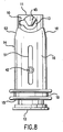
- Figure 8 illustrates the same where there is only one die 13 in extrusion wall 10, since that die 13 simulates a small chicken drumstick and is so large that multiple dies 13 in extrusion wall 10 would very substantially decrease the pressure of the mash in extrusion wall 10 when the die is open.
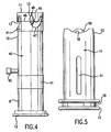
- the outside surfaces, generally 40, of extrusion wall 10 have at least one bearing surface 41 upon which the cutter member 14 is reciprocally slid.
- Figure 4 shows two such bearing surfaces, but one or up to about ten such bearing surfaces, or more, may be used. These bearing surfaces 41 snugly fit the inside surface 50 (see Figure 5) of cutter member 14 so as to have a precise slide and cutting action when reciprocated over die 13.
- bearing surfaces may be simply machined portions on extrusion wall 10 or on the inside surface of tubular cutter member 14, they may also be separate bearings made of special bearing material to increase the life of the bearings, e.g. bearing grade steel, oil-impregnated sintered bearings, and the like.
- bearings are constituted by a bearing plastic sleeve mounted into the insider surface 50 of cutter member 14.
- Such sleeve can be so mounted in a number of ways, but preferably the cutter member 14 has a recess formed in the inside surface 50 thereof. After placing the sleeve into that recess, the inside diameter of the sleeve is formed, e.g. bored or machined, to a precise dimension which is, for example, only 1 / 254 metre (1/10,000 inch) greater than the outside diameter of extrusion wall 10.
- an engineering plastic one which has abrasion resistance, high strength and high incompressibility
- materials such as HYDEX
- reciprocations of 500 to 800 cycles per minute can be sustained for many days without the bearings loosening.
- the bearing sleeve may be held in the recess by any conventional means such as a shoulder or retention ring.
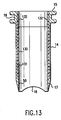
- Figure 13 shows an example of such a bearing plastic sleeve 130 disposed in a recess 131 on the inside wall 50 of cutter member 14.
- the plastic sleeve may be held within recess 131 by a shoulder or retention ring 132.
- a slot 51 (see Figures 5 and 2) is provided in tubular cutter member 14 and an upstanding protuberance, e.g. a stud, 42 (see Figures 4 and 2) is attached to extrusion wall 10 and projects through slot 51.
- an upstanding protuberance e.g. a stud, 42
- the cutting surface remains in register with the extrusion die.
- the simplest form of keeping the cutting surface in register with the extrusion die is that of the stud 42 being threadedly engaged into the extruder wall 10, but, obviously, many other equivalent mechanical devices could be used to achieve the same result, e.g. a key and slot arrangement, a guide and pin arrangement, and the like.
- a most preferred form of the invention is where in the closed extrusion end 11 has an at least partially conical extrudate divertor 45 (see Figures 4 and 2) projecting into the annulus of the tubular extrusion wall 10 and extending at least to a diameter 46 (see Figures 4 and 2) of the extrusion wall 10 lying within the extrusion die 13. Most preferably, that divertor 45 is in a truncated conical shape.
- the purpose of the divertor is to encounter the mash flowing through extrusion wall 10 and diverting that main flow from an essentially axial flow to a substantial transverse flow whereby the mash encounters the die 13 in a transverse direction so as to decrease turbulence of the mash passing through the die. With this decreased turbulence of the mash, a more uniform and predictable shape of the extrudate is provided.
- the cutter wall 16 has a length sufficient such that a leadingmost edge of the cutting surface 18 extends beyond the closed extrusion end 11 when the cutter wall is slid to a furthest extension of a reciprocating movement. By such extension of the cutting surface 18 beyond the die 13, it will be ensured that there are no stringers between successive cut extrudates. However, to completely ensure this lack of stringers, it is most preferred that a trailingmost edge of the cutting surface 18 also extends beyond the closed extrusion end 11.
- the cutting surface 18 may be at least in part tapered in the axial direction, as shown by the taper 53 in Figures 5 and 8.
- the extrusion wall 10 and the cutter wall 16 have a circular cross-section, this will facilitate any pressure drop caused by flow of the mash therethrough and improve the accuracy of the extrudate shape.
- the extrusion wall 10 and the cutter wall 16 may have other shapes, such as square, rectangular, oval and polyhedral shapes. Any shape other than a circular shape, i.e. circular cross-section, will not require the protuberance 42, since such shapes will be self-aligning and, in that sense, are an advantage. However, other than a circular cross-section can cause non-uniform flow of the mash and, therefore, is not preferred.
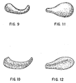
- Figure 9 shows a simulated fried shrimp produced according to the invention, and it will be noted that the configuration is generally that of a shrimp and also is in a rounded configuration as a result of the practice of the invention.
- Figure 10 shows a similar extrusion, according to the prior art, as explained above, and it will be noted that the shape is distorted from that of a usual French fried shrimp, and, most importantly, instead of being rounded, the shape is somewhat squarish, which, of course, is not at all like a natural fried piece.
- Figures 11 and 12 which simulate small chicken drumsticks (see Figure 8).
- the product of the present invention as shown in Figure 11, is rounded, while the product of the prior art is somewhat distorted and, again, does not have the rounded shape but something of a squarish shape.
- the mash may be prepared from any food, e.g. meats, poultry, seafood, cereal grains, vegetables, fruits and solid dairy products.
- the mash may be prepared from beef, chicken, shrimp, wheat, corn, rice, potatoes, apples and cheese.
- the food is ground to a particle size consistent with forming a fluid mash, e.g. particle sizes that will pass through a U. S. Screen Series No. 5 screen, more usually a No. 10 screen and often a No. 20 screen up to about a No. 100 screen.
- Water or other dispersing liquids may be added to the ground food in order to produce a liquid mash.
- Binders, flavors, preservatives, colors, stabilizers, antioxidants, and the like may be added to the mash, in conventional amounts.
- a gelling material is added to the mash, e.g. a settable gum or pectate, for example, guar gum and sodium alginate, in conventional amounts of about 0.1% to 25%.
- the gum or pectate is set by a gelling agent, as explained above, e.g. a 0.5% to 10% solution of calcium chloride.
- the pressure on the pressure vessel will vary considerably from mash to mash and die to die, but pressures of 0.07 to 3.45 bar (1 to 50 psig) are normally used, and especially with usual mash temperatures of - 3,9°C to 10°C (25°F to 50°F).
- the term “substantially” means that the change is sufficient to cause a visually noticeable different configuration of the extruded and cut food pieces.
- the die is configured to provide a substantially constant transverse flow rate of the mash through the die at substantially all portions of the die.
- the term “substantially” in this regard means that the flow rate is such that the extruded and cut food piece does not substantially visually noticeably vary from the desired simulated food piece.
- the same meaning is also intended for like terms in the specification, e.g. relatively.
Landscapes
- Engineering & Computer Science (AREA)
- Mechanical Engineering (AREA)
- Manufacturing & Machinery (AREA)
- Life Sciences & Earth Sciences (AREA)
- Food Science & Technology (AREA)
- Formation And Processing Of Food Products (AREA)
Description
The present improvement in that known extruder is where the curved edge of the extrusion die is generally configured to a cross-sectional shape of the natural food piece but which die is also configured so as to provide a substantially constant transverse flow rate of the mash through the die at substantially all portions of the die, the drive device is arranged to reciprocate the cutter member at speeds sufficient that the cutter member is disposed over the die for a time period such that a pressure of the mash in the tubular extrusion wall is not substantially changed during a reciprocation of the cutter member, and the cutting surface shape is generally approximating the shape of the at least first one-quarter of the die first encountered by the cutting surface when cutting a food piece.
Claims (26)
- An extruder for producing an extruded food piece in a shape which simulates the shape of a natural food piece comprising a pressure vessel (2) for containing a mash of the food under pressure, a pressure exerting device (3) for maintaining a pressure in the pressure vessel, a manifold (4) in fluid communication with the pressure vessel, and at least one die and cutter assembly (6) in fluid communication with the manifold, said die and cutter assembly havingcharacterized in that the curved edge (47) of the extrusion die (13) is generally configured to a cross-sectional shape of said natural food piece but which die is configured so as to provide a substantially constant transverse flow rate of the mash through the die at substantially all portions of the die, and the drive device is operable to reciprocate the cutter member at speeds sufficient that the cutter member (14) is disposed over the die for a time period that a pressure of the mash in the tubular extrusion wall is not substantially changed during a reciprocation of the cutter member, and the cutting surface (18) is generally approximating the shape of the at least first one-quarter of the die first encountered by the cutting surface when cutting a food piece.(a) an elongated, annular extrusion member (9) with a tubular extrusion wall (10),(b) a closed extrusion end (11),(c) an opened feed end attachable in fluid communication to the manifold,(d) at least one extrusion die (13) formed in the tubular extrusion wall (10) near the extrusion end, and having an axially curved edge (47).(e) a tubular cutter member (14) having an opened driveable end, an elongated cutter wall (16) and an opened cutter end with at least one axially curved cutting surface (18) for cutting extrudate into said shape as the extrudate exits the die, said cutter member being disposed at least partially over and reciprocally slideable on the tubular extrusion wall and operably connected at the driveable end to a drive device (20) for reciprocatably sliding the cutter member over and away from the die,
- A die and cutter assembly (6) for an extruder, comprising :characterized in that the curved edge (47) of the extrusion die (13) is generally configured to a cross-sectional shape of said natural food piece but which die is configured so as to provide a substantially constant transverse flow rate of the mash through the die at substantially all portions of the die, and the cutter member (14) is reciprocatable by the drive device at speeds sufficient that the cutter member is disposed over the die for a time period that a pressure of the mash in the tubular extrusion wall is not substantially changed during a reciprocation of the cutter member, and the cutting surface (18) is generally approximating the shape of the at least first one-quarter of the die first encountered by the cutting surface when cutting a food piece.an elongated, annular extrusion member (9) with a tubular extrusion wall (10);a closed extrusion end (11);an opened feed end attachable in fluid communication to the extruder;at least one extrusion die (13) formed in the tubular extrusion wall (10) near the extrusion end and having an axially curved edge (47);a tubular cutter member (14) having an opened driveable end, an elongated cutter wall (16) and an opened cutter end with at least one axially curved cutting surface (18) for cutting extrudate into said shape as the extrudate exits the die, said cutter member being disposed at least partially over and reciprocally slideable on the tubular extrusion wall and able in use connect at the driveable end to a drive device (20) of the extruder for reciprocatably sliding the cutter member over and away from the die;
- A device according to claim 1 or claim 2, wherein the cutter member is reciprocated over the die at a rate of between about 60 and 800 cycles per minute.
- A device according to claim 3, wherein the rate is between about 150 and 700 cycles per minute.
- A device according to claim 4, wherein the rate is between about 300 and 600 cycles per minute.
- A device according to claim 1 or claim 2, having at least one bearing (41) between said tubular extrusion wall and said cutter member.
- A device according to claim 1 or claim 2, wherein the cutter wall has an axial slot (51) and the extrusion wall has an upstanding protuberance (42) disposed within said slot such that the cutting surface remains in register with the extrusion die.
- A device according to claim 7, wherein the protuberance is a stud (42) threadedly engaged in the extrusion wall.
- A device according to claim 1 or claim 2, wherein the closed extrusion end has an at least partially conical extrudate divertor (45) projecting into an annulus of the tubular extrusion wall (10) and extending at least to a diameter of the extrusion wall lying within the extrusion die.
- A device according to claim 9, wherein the divertor (45) is in a truncated conical shape.
- A device according to claim 1 or claim 2, wherein the cutter wall (14) has a length sufficient such that a leadingmost edge of the cutting surface extends beyond the closed extrusion end when the cutter wall is slid to a furthest extension of a reciprocating movement.
- A device according to claim 11, wherein a trailingmost edge of the cutting surface extends beyond the closed extrusion end.
- A device according to claim 1 or claim 2, wherein there are at least two dies (13) in the extrusion wall and at least two cutting surfaces (18) on the cutter wall.
- A device according to claim 6, wherein said at least one bearing includes at least two bearing surfaces (41).
- A device according to claim 14, wherein one of said bearing surfaces (41) has the at least one die (13) disposed therein.
- A device according to claim 9, wherein the divertor (45) extends into the annulus of the tubular extrusion wall such that a smallest end of the divertor lies on a said diameter which is approximately equidistant between opposite axial edges of the die (13).
- A device according to claim 1 or claim 2, wherein the cutting surface (18) at least in part is tapered in the axial direction.
- A device according to claim 1 or claim 2, wherein the extrusion wall (10) and the cutter wall (14) have a circular cross-section.
- A device according to claim 6, wherein an inside surface of the cutter wall (14) has cross-sectional dimensions slightly greater than outer cross-sectional dimensions of a bearing surface (41) such that the cutter wall is snugly slideable on the bearing surface.
- A device according to claim 1 or claim 2, wherein there is a plastic sleeve bearing (41) between the extrusion wall (10) and the cutter wall (14).
- A device according to claim 20, wherein the sleeve bearing (41) is made of an engineering plastic.
- A device according to claim 1 or claim 2, wherein said cutting surface (18) is non-horizontal.
- A device according to claim 6, wherein said at least one bearing (41) is a raised portion or portions of said tubular extrusion wall or said tubular cutter member.
- A device according to claim 6, wherein said at least one bearing (41) is a separate bearing sleeve made of a material different from a material of said tubular extrusion wall and/or said tubular cutter member;
- A device according to claim 24, wherein said separate bearing sleeve (41) is made of an engineering plastic.
- A device according to claim 6, wherein said at least one bearing (41) includes said at least one extrusion die (13) formed therein.
Applications Claiming Priority (3)
| Application Number | Priority Date | Filing Date | Title |
|---|---|---|---|
| US08/816,030 US5773043A (en) | 1997-03-11 | 1997-03-11 | Extruder and die assembly for extruding shaped food pieces |
| US816030 | 1997-03-11 | ||
| PCT/US1998/003211 WO1998039975A1 (en) | 1997-03-11 | 1998-02-18 | Extruder and die assembly for extruding shaped food pieces |
Publications (3)
| Publication Number | Publication Date |
|---|---|
| EP0966198A1 EP0966198A1 (en) | 1999-12-29 |
| EP0966198A4 EP0966198A4 (en) | 2001-09-05 |
| EP0966198B1 true EP0966198B1 (en) | 2005-06-22 |
Family
ID=25219509
Family Applications (1)
| Application Number | Title | Priority Date | Filing Date |
|---|---|---|---|
| EP98906565A Expired - Lifetime EP0966198B1 (en) | 1997-03-11 | 1998-02-18 | Extruder and die assembly for extruding shaped food pieces |
Country Status (8)
| Country | Link |
|---|---|
| US (1) | US5773043A (en) |
| EP (1) | EP0966198B1 (en) |
| JP (1) | JP3959122B2 (en) |
| AU (1) | AU720495B2 (en) |
| CA (1) | CA2283967C (en) |
| DE (1) | DE69830651T2 (en) |
| NZ (1) | NZ337751A (en) |
| WO (1) | WO1998039975A1 (en) |
Families Citing this family (29)
| Publication number | Priority date | Publication date | Assignee | Title |
|---|---|---|---|---|
| US6511309B1 (en) | 2000-05-24 | 2003-01-28 | Kerry, Inc. | Extruder die and cutter assembly for extruding filled food pieces |
| AU2001289005B2 (en) * | 2001-09-12 | 2007-08-02 | Kerry Inc | Extruder die assembly |
| US6586031B1 (en) * | 2002-05-21 | 2003-07-01 | Recot, Inc. | Method for producing expanded, shaped pellet products |
| US6964562B2 (en) * | 2002-06-11 | 2005-11-15 | Kerry, Inc. | Extruder die and cutter assembly for extruding filled food pieces |
| AU2003301213B2 (en) * | 2002-12-30 | 2009-12-03 | Kerry, Inc. | Cutter assembly for extruding shaped food pieces |
| NO319624B1 (en) | 2003-09-15 | 2005-09-05 | Trouw Internat Bv | Fish feed for salmonids in fresh water and use of such feed. |
| US7316557B2 (en) * | 2004-05-08 | 2008-01-08 | Good Earth Tools, Inc. | Die for extruding material |
| US7513676B2 (en) * | 2004-05-08 | 2009-04-07 | Good Earth Tools, Inc. | Extruder screw with long wearing surfaces |
| NO323529B1 (en) * | 2004-05-13 | 2007-06-04 | Trouw Internat Bv | Procedure for reducing the content of undesirable nutrients in wastewater from fish farms. |
| US20060162580A1 (en) * | 2004-09-15 | 2006-07-27 | Lowry Stanley N | Methods and apparatuses for cutting dough utilizing an insert or shaped plate |
| US8002534B2 (en) | 2004-09-15 | 2011-08-23 | Lowry Stanley N | Methods and apparatuses for cutting dough utilizing a shaped opening |
| US8047834B2 (en) * | 2005-08-19 | 2011-11-01 | Dixie Consumer Products Llc | Segmented pressware die set with anti-twist guide keys |
| USD536506S1 (en) * | 2005-12-22 | 2007-02-13 | Mars, Incorporated | Edible pet chew |
| US7963500B1 (en) * | 2006-12-06 | 2011-06-21 | Holiday Angela C | Snowman mold |
| AU2008216380A1 (en) | 2007-02-13 | 2008-08-21 | John Desautels | A personal affector machine |
| US7771767B2 (en) * | 2007-02-21 | 2010-08-10 | Kerry, Inc. | Extrusion die with extrusion ports having a shaped extrusion outlet |
| US8579623B2 (en) * | 2008-04-10 | 2013-11-12 | Edward Williams | Extruder stabilizer assembly |
| EP2293672A2 (en) * | 2008-04-16 | 2011-03-16 | Kerry, Inc. | Co-extruder having a filling entrance from the rear |
| AU2009244343A1 (en) * | 2008-05-06 | 2009-11-12 | Kerry, Inc. | Extrusion die with extrusion port having a shaped extrusion outlet |
| US8152506B1 (en) | 2008-05-21 | 2012-04-10 | Atoor Khoshaba | Pressure generating device with food compressing attachment |
| WO2010006444A1 (en) * | 2008-07-18 | 2010-01-21 | Sun-Rype Products Ltd. | Method and system for extruding a consumable end fruit product |
| US8621989B2 (en) * | 2008-10-06 | 2014-01-07 | Franz Haas Waffel- Und Keksanlagen-Industrie Gmbh | Food manufacturing apparatus and related method |
| NO340652B1 (en) * | 2009-06-25 | 2017-05-22 | Trouw Int Bv | Feed block and method of preparation of feed block |
| US20110081438A1 (en) * | 2009-10-06 | 2011-04-07 | Kerry, Inc. | Extruder die and cutter assembly having an extrusion die with a shaped extrusion port and a filling tube |
| US20110088530A1 (en) * | 2009-10-17 | 2011-04-21 | Arbaugh Ii William C | Cheese/food extrusion cutting die blade, process of use and process of production |
| ITVI20120314A1 (en) * | 2012-11-22 | 2014-05-23 | Lmt Srl | EXTRUSION MATRIX AND EXTRUSION METHOD OF A FOOD PRODUCT BY SUCH A MATRIX |
| KR101602857B1 (en) * | 2015-10-14 | 2016-03-11 | 김문국 | Apparatus for feeding fixed amount of bakery material |
| CN114342971A (en) * | 2022-01-10 | 2022-04-15 | 安徽顶康食品有限公司 | Die assembly for biscuit processing |
| CN119423329A (en) * | 2023-07-28 | 2025-02-14 | 好为尔机械(山东)有限公司 | 3D extrusion molding machine |
Family Cites Families (8)
| Publication number | Priority date | Publication date | Assignee | Title |
|---|---|---|---|---|
| US2101755A (en) * | 1935-10-11 | 1937-12-07 | Samuel D Rosenstone | Slicing machine |
| US2676552A (en) * | 1950-06-29 | 1954-04-27 | Doughnut Corp Of America | Method of forming rings of yeasted dough |
| US3143085A (en) * | 1960-10-12 | 1964-08-04 | Dca Food Ind | Adjustable cutter disc |
| US4080137A (en) * | 1975-12-24 | 1978-03-21 | Dca Food Industries Inc. | Apparatus for forming bodies with an arcuate top and a flat bottom |
| US4152102A (en) * | 1977-05-06 | 1979-05-01 | Modern Maid Food Products, Inc. | Apparatus for the preparation of extruded food products |
| US5304055A (en) * | 1991-11-27 | 1994-04-19 | Nabisco, Inc. | Apparatus and methods for the production of three-dimensional food products |
| US5591384A (en) * | 1994-03-31 | 1997-01-07 | Modern Technologies Corp. | Method for molding parts |
| US5578337A (en) * | 1995-02-02 | 1996-11-26 | Rich Sea-Pak Corporation | Process for extruding gelled product |
-
1997
- 1997-03-11 US US08/816,030 patent/US5773043A/en not_active Expired - Lifetime
-
1998
- 1998-02-18 AU AU61755/98A patent/AU720495B2/en not_active Ceased
- 1998-02-18 WO PCT/US1998/003211 patent/WO1998039975A1/en not_active Ceased
- 1998-02-18 EP EP98906565A patent/EP0966198B1/en not_active Expired - Lifetime
- 1998-02-18 DE DE69830651T patent/DE69830651T2/en not_active Expired - Lifetime
- 1998-02-18 CA CA002283967A patent/CA2283967C/en not_active Expired - Fee Related
- 1998-02-18 JP JP53957198A patent/JP3959122B2/en not_active Expired - Fee Related
- 1998-02-18 NZ NZ337751A patent/NZ337751A/en not_active IP Right Cessation
Also Published As
| Publication number | Publication date |
|---|---|
| CA2283967A1 (en) | 1998-09-17 |
| WO1998039975A1 (en) | 1998-09-17 |
| DE69830651T2 (en) | 2006-05-04 |
| US5773043A (en) | 1998-06-30 |
| EP0966198A1 (en) | 1999-12-29 |
| AU6175598A (en) | 1998-09-29 |
| AU720495B2 (en) | 2000-06-01 |
| EP0966198A4 (en) | 2001-09-05 |
| CA2283967C (en) | 2006-04-25 |
| JP3959122B2 (en) | 2007-08-15 |
| JP2002504807A (en) | 2002-02-12 |
| DE69830651D1 (en) | 2005-07-28 |
| NZ337751A (en) | 2001-03-30 |
Similar Documents
| Publication | Publication Date | Title |
|---|---|---|
| US5773043A (en) | Extruder and die assembly for extruding shaped food pieces | |
| Harper et al. | Food extrusion | |
| Riaz | Introduction to extruders and their principles | |
| US6143338A (en) | Puffed food product having body with intersecting colored lines | |
| AU2003207482B2 (en) | Method and apparatus for producing a braided puff extrudate | |
| US5643618A (en) | Apparatus for making multiple, complexly patterned extrudates | |
| CA2304087C (en) | Fibrous food product and method and device for its production | |
| US5458900A (en) | Methods for making arepas | |
| US4800094A (en) | Method for processing a cooked food product | |
| WO2017125296A1 (en) | Apparatus for producing a food item | |
| CN101827533A (en) | Extruded legume snack food | |
| US20080089970A1 (en) | Cutter assembly for extruding shaped food pieces | |
| AU2008218669B2 (en) | Extrusion die with extrusion ports having a shaped extrusion outlet | |
| CN107251986B (en) | A kind of polysaccharide improvement high-moisture peanut wire-drawing protein quality method | |
| GB2270613A (en) | Making snack food | |
| KR20000009635A (en) | Process for seasoned bar rice cake feeded internal filling to stick of rice cake and apparatus | |
| MXPA99006146A (en) | Extruder and die assembly for extruding shaped food pieces | |
| CN209173861U (en) | A kind of bean product mechanized production system | |
| CN209950313U (en) | Glue powder fish cutlet production and use coating device | |
| KR20250086298A (en) | Tteokbokki rice cake manufacturing equipment and Tteokbokki rice cakes manufactured by the manufacturing equipment | |
| EP0423598A3 (en) | Corn snacks and method of manufacture | |
| CN86100203A (en) | Preparation of stuffing strip and stuffing-strip machine |
Legal Events
| Date | Code | Title | Description |
|---|---|---|---|
| PUAI | Public reference made under article 153(3) epc to a published international application that has entered the european phase |
Free format text: ORIGINAL CODE: 0009012 |
|
| 17P | Request for examination filed |
Effective date: 19990810 |
|
| AK | Designated contracting states |
Kind code of ref document: A1 Designated state(s): DE FR GB IE |
|
| A4 | Supplementary search report drawn up and despatched |
Effective date: 20010725 |
|
| AK | Designated contracting states |
Kind code of ref document: A4 Designated state(s): DE FR GB IE |
|
| RIC1 | Information provided on ipc code assigned before grant |
Free format text: 7A 21C 11/10 A, 7A 21C 11/16 B, 7B 29C 47/30 B, 7B 30B 11/22 B |
|
| 17Q | First examination report despatched |
Effective date: 20021105 |
|
| GRAP | Despatch of communication of intention to grant a patent |
Free format text: ORIGINAL CODE: EPIDOSNIGR1 |
|
| GRAS | Grant fee paid |
Free format text: ORIGINAL CODE: EPIDOSNIGR3 |
|
| GRAA | (expected) grant |
Free format text: ORIGINAL CODE: 0009210 |
|
| AK | Designated contracting states |
Kind code of ref document: B1 Designated state(s): DE FR GB IE |
|
| REG | Reference to a national code |
Ref country code: GB Ref legal event code: FG4D |
|
| REG | Reference to a national code |
Ref country code: IE Ref legal event code: FG4D |
|
| REF | Corresponds to: |
Ref document number: 69830651 Country of ref document: DE Date of ref document: 20050728 Kind code of ref document: P |
|
| ET | Fr: translation filed | ||
| PLBE | No opposition filed within time limit |
Free format text: ORIGINAL CODE: 0009261 |
|
| STAA | Information on the status of an ep patent application or granted ep patent |
Free format text: STATUS: NO OPPOSITION FILED WITHIN TIME LIMIT |
|
| 26N | No opposition filed |
Effective date: 20060323 |
|
| PGFP | Annual fee paid to national office [announced via postgrant information from national office to epo] |
Ref country code: FR Payment date: 20120221 Year of fee payment: 15 Ref country code: IE Payment date: 20120210 Year of fee payment: 15 |
|
| PGFP | Annual fee paid to national office [announced via postgrant information from national office to epo] |
Ref country code: DE Payment date: 20120215 Year of fee payment: 15 |
|
| PGFP | Annual fee paid to national office [announced via postgrant information from national office to epo] |
Ref country code: GB Payment date: 20120215 Year of fee payment: 15 |
|
| GBPC | Gb: european patent ceased through non-payment of renewal fee |
Effective date: 20130218 |
|
| REG | Reference to a national code |
Ref country code: FR Ref legal event code: ST Effective date: 20131031 |
|
| REG | Reference to a national code |
Ref country code: IE Ref legal event code: MM4A |
|
| REG | Reference to a national code |
Ref country code: DE Ref legal event code: R119 Ref document number: 69830651 Country of ref document: DE Effective date: 20130903 |
|
| PG25 | Lapsed in a contracting state [announced via postgrant information from national office to epo] |
Ref country code: FR Free format text: LAPSE BECAUSE OF NON-PAYMENT OF DUE FEES Effective date: 20130228 Ref country code: GB Free format text: LAPSE BECAUSE OF NON-PAYMENT OF DUE FEES Effective date: 20130218 Ref country code: IE Free format text: LAPSE BECAUSE OF NON-PAYMENT OF DUE FEES Effective date: 20130218 Ref country code: DE Free format text: LAPSE BECAUSE OF NON-PAYMENT OF DUE FEES Effective date: 20130903 |
|
| P01 | Opt-out of the competence of the unified patent court (upc) registered |
Effective date: 20230530 |