EP0966149A2 - Data-reading image capture apparatus, camera, and method of use - Google Patents
Data-reading image capture apparatus, camera, and method of use Download PDFInfo
- Publication number
- EP0966149A2 EP0966149A2 EP99201797A EP99201797A EP0966149A2 EP 0966149 A2 EP0966149 A2 EP 0966149A2 EP 99201797 A EP99201797 A EP 99201797A EP 99201797 A EP99201797 A EP 99201797A EP 0966149 A2 EP0966149 A2 EP 0966149A2
- Authority
- EP
- European Patent Office
- Prior art keywords
- image
- radiation
- band
- invisible
- data
- Prior art date
- Legal status (The legal status is an assumption and is not a legal conclusion. Google has not performed a legal analysis and makes no representation as to the accuracy of the status listed.)
- Withdrawn
Links
Images


Classifications
-
- G—PHYSICS
- G03—PHOTOGRAPHY; CINEMATOGRAPHY; ANALOGOUS TECHNIQUES USING WAVES OTHER THAN OPTICAL WAVES; ELECTROGRAPHY; HOLOGRAPHY
- G03B—APPARATUS OR ARRANGEMENTS FOR TAKING PHOTOGRAPHS OR FOR PROJECTING OR VIEWING THEM; APPARATUS OR ARRANGEMENTS EMPLOYING ANALOGOUS TECHNIQUES USING WAVES OTHER THAN OPTICAL WAVES; ACCESSORIES THEREFOR
- G03B11/00—Filters or other obturators specially adapted for photographic purposes
-
- H—ELECTRICITY
- H04—ELECTRIC COMMUNICATION TECHNIQUE
- H04N—PICTORIAL COMMUNICATION, e.g. TELEVISION
- H04N1/00—Scanning, transmission or reproduction of documents or the like, e.g. facsimile transmission; Details thereof
- H04N1/00127—Connection or combination of a still picture apparatus with another apparatus, e.g. for storage, processing or transmission of still picture signals or of information associated with a still picture
-
- H—ELECTRICITY
- H04—ELECTRIC COMMUNICATION TECHNIQUE
- H04N—PICTORIAL COMMUNICATION, e.g. TELEVISION
- H04N2101/00—Still video cameras
-
- H—ELECTRICITY
- H04—ELECTRIC COMMUNICATION TECHNIQUE
- H04N—PICTORIAL COMMUNICATION, e.g. TELEVISION
- H04N2201/00—Indexing scheme relating to scanning, transmission or reproduction of documents or the like, and to details thereof
- H04N2201/0008—Connection or combination of a still picture apparatus with another apparatus
- H04N2201/0063—Constructional details
-
- H—ELECTRICITY
- H04—ELECTRIC COMMUNICATION TECHNIQUE
- H04N—PICTORIAL COMMUNICATION, e.g. TELEVISION
- H04N2201/00—Indexing scheme relating to scanning, transmission or reproduction of documents or the like, and to details thereof
- H04N2201/0008—Connection or combination of a still picture apparatus with another apparatus
- H04N2201/007—Selecting or switching between a still picture apparatus or function and another apparatus or function
Definitions
- the invention relates to image capture apparatus including photographic cameras and more particularly relates to a data-reading image capture apparatus, a data-reading camera, and a method of using the camera.
- EP Patent Application No. 98202964.7 filed September 4, 1998, discloses the use of a printed invisible encodement on a photographic image to record sound information.
- the encodement is read by illuminating using a beam of invisible electromagnetic radiation that is subject to modulation by the encodement.
- the resulting encodement image is captured, decoded, and played back.
- the photographic image on which the encodement is printed is originally captured using a camera.
- the invisible radiation image is captured using a reader that is capable of capturing only invisible images within a selected band.
- band is used herein to refer to one or more contiguous or non-contiguous regions of the electromagnetic spectrum.
- invisible is used herein to describe material which is invisible or substantially invisible to the human eye when viewed under normal viewing conditions, that is, facing the viewer and under sunlight or normal room illumination such as incandescent lighting.
- the invisible image is produced by development of a photographic emulsion layer, ink jet printing, thermal dye transfer printing or other printing method.
- the encodement is a one or two-dimensional array of encoded data.
- Digital cameras and other visible image capture apparatus utilize a visible light sensitive electrical device. At least some of these light sensitive devices are also sensitive to invisible radiation.
- Charge coupled devices CCD's are so sensitive to infrared radiation that attenuation is required during capture of the visible light image. This is generally accomplished by permanently mounting an infrared blocking filter in the optical system of the camera or other capture device.
- the invention in its broader aspects, provides a data-reading image capture apparatus, camera, and method of use.
- the capture apparatus has a digital image detector sensitive to a band of visible radiation and a band of invisible electromagnetic radiation.
- An optical system in the capture apparatus, focuses the bands of electromagnetic radiation on the image detector.
- An image separator is disposed in the capture apparatus, in operative relation to the digital image detector and optical system. The image separator is switchable between an image capture state and a data reading state.
- the image separator is attenuative for the band of invisible radiation and transmissive for the band of visible radiation in the image capture state.
- the image separator is attenuative for the band of visible radiation and transmissive for the band of invisible radiation in the data reading state.
- a data-reading image capture apparatus a data-reading camera, and a method of using the camera are provided which allow for capture of visible images and images of invisible encodements without the need for both a camera and a separate encodement reader.
- the data-reading image capture apparatus 10 is a camera, scanner, or other imager that has an exposure system 12 that can capture both a visible radiation image and a second image, separate from the visible radiation image.
- the captured second image is invisible; that is, the second image is formed by radiation in a band outside the visible spectrum.
- the second image is reflection, transmission, or luminance from an invisible layer that overlies a visible image.
- the visible image can be limited to an underlying substrate without information content, but ordinarily would be printed information, in the form of pictorial information, text or other alphanumeric information, or non-alphanumeric indicia. The nature, content, and manner of preparation of the printed image is not critical.
- the invisible layer can simply be a pictorial image or indicia, but is preferably in the form of a data encodement.
- the capture of the invisible second image is also sometimes referred to herein by the term, "data reading” and similar terms.
- a camera of the invention can be used to both photograph a subject and to read data invisibly imprinted on a photograph print. (This is illustrated in Figures 4 and 9 as a sheet 14 bearing a visible printed image 16 of a pair of trees. The word "DATA" appears in dashed lines, to represent the invisible encodement 18.)
- the data in the encodement can include subject specific information, such as sound recorded when the picture was taken, for playback at the time of viewing the photographic print or other use.
- the encodement can be in accordance with Standard PDF 417 and the L549042D Scanner System marketed by Symbol Technologies, Inc., of Holtsville, New York; or the encodement scheme marketed as Paper Disk by Cobblestone Software, Inc., of Lexington, Massachusetts.
- the invention is discussed herein generally in terms of a camera 10, that is, a portable general purpose image capturing apparatus; but it will be understood that equivalent features are intended for other data-reading image capture apparatus, such as flatbed and media transport scanners.
- the invention is also discussed herein generally in terms of a visible radiation image and an invisible encodement.
- the visible image can include a small percentage of invisible radiation (also referred to herein as an "invisible component”).
- the invisible encodement is preferably fully invisible under ordinary viewing conditions, but can include a small percentage of visible radiation (also referred to herein as a "visible component").
- An invisible component of the visible image is inconsequential unless the component is in the same radiation band as the invisible encodement.
- the invisible component can act as background noise and reduce the signal to noise ratio of the invisible encodement.
- the amplitude of the invisible component should be insufficient to measurably degrade a digital image produced from the invisible encodement when the invisible encodement is read. Any visible component of the invisible encodement should, preferably, be imperceptible to the viewer under ordinary viewing conditions; but slight degradation of the image may be acceptable under some conditions.
- the invisible encodement can absorb the invisible radiation or can reflect and/or emit the invisible radiation.
- the frequency range or ranges of the invisible radiation is dependent upon the characteristics of the material used for the invisible encodement.
- infrared radiation or ultraviolet radiation or both can be used. High frequency ultraviolet radiation and radiation of higher frequency is not preferred in current embodiments for reasons of safety. Infrared radiation is preferred over ultraviolet for the same reason.
- the camera 10a includes the exposure system 12, a body 20 supporting the exposure system 12, and a control interface accessible from the outside of the body 20 for controlling the exposure system 12.
- the control interface includes a shutter button 22.
- the exposure system 12 includes a capture unit 24 and an optical system 26 (illustrated in Figures 1-2 as a circle) that focuses electromagnetic radiation on the capture unit 24.
- the capture unit 24 includes a digital image detector 28 that is sensitive to a band of visible radiation and a band of invisible electromagnetic radiation.
- the digital image detector 28 is used to capture the invisible second image.
- the digital image detector 28 comprises one or more radiation-sensitive electrical devices which convert an impinging radiation beam into a digital image, that is, an electrical signal from which a two dimensional image can be reconstructed. It is currently preferred to use light-sensitive electrical devices that are sensitive to a broad band of radiation including all or most of the visible spectrum and a selected band of invisible radiation. For example, widely available charge coupled devices (CCD's) are sensitive to visible radiation and a broad band of infrared radiation.
- the light-sensitive electrical device can also be a charge injection device, a photodiode, a CMOS imager, or another type of photoelectric transducer.
- the digital image detector 28 can include one or more two-dimensional light-sensitive electrical devices, or one or more two dimensional arrays of such devices, or one or more one-dimensional arrays of such devices. With one-dimensional arrays, the detector includes means, well known to those of skill in the art, for scanning the incident beam to provide a two-dimensional digital image. Two-dimensional devices are preferred over one dimensional devices and the use of single discrete devices is currently preferred over the use of arrays of smaller devices for reasons of image quality and ease of assembly. It is well known in the art to use a single two-dimensional capture device with a pixellated three-color filter for color visible image capture. It is also well known to use three two-dimensional devices with a beam splitter and individual colored filters.
- An example of a suitable digital image detector 28 comprises a single CCD, such as a charge coupled device marketed by Eastman Kodak Company of Rochester, New York as Model No. KAF-6300. Lower resolution digital image detectors can also be used, such as a VGA (video graphics array) sensor having a resolution of 640 by 480 pixels.
- the camera of the invention can be prepared by modifying an existing digital camera, such as a DCS-210, marketed by Eastman Kodak Company of Rochester, New York, to add a filter holder (described in detail below).
- the digital image detector 28 can be used for capture of the visible image.
- the digital image detector 28 is utilized for visible image capture in the same manner as in the various digital cameras well known to those of skill in the art.
- a visible image capture component 30 can be used.
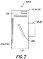
- the visible image capture component 30 can be digital, using the same kinds of components as previously described for the digital image detector 28; or can utilize photographic film, as shown in Figure 7. Suitable photographic film camera features, such as exposure, film metering, and film transport mechanisms, are well known to those of skill in the art.
- the exposure system 12 of the capture apparatus 10 includes an image separator 32, for separating the visible light and invisible radiation images.
- the image separator 32 can be in the form of one or more digital computer programs or subroutines (hereafter "software"), or can be limited to physical features of the capture apparatus 10, such as optical filters, or can combine physical features and software.
- the image separator 32 can switch automatically between visible image capture and data reading states or can be selectively alternated by the user.
- selective alternation by the user is preferred.
- the manner of alternating the states is not critical, but should not interfere with usage of the capture apparatus 10 in either state.
- optical filters can be alternated by detachment and reattachment or, more preferably, by use of any of a wide variety of linear and rotary motion mechanisms to move the filters.
- the image separator 32 is a mirror that, in a first position 32a (indicated by solid lines), directs light to the digital image detector 28; and, in a second position 32b (indicated by dashed lines), directs light to photographic film or digital visible image capture component 30.
- Suitable mirror mechanisms are well known to those of skill in the art, since similar mirror mechanisms are used in single lens reflex cameras. A fixed half-silvered mirror could also be used.
- the image separator 32 of Figure 7 is not preferred since it is relatively complex and requires separate invisible and visible light detectors 28,30, respectively.
- the image separator 32 uses one or more optical filters. This approach is simple and relatively inexpensive and is therefore currently preferred.
- the image separator 32 in order to separate out the invisible image, includes a data filter 36 attenuative for the band of visible radiation to which the digital image detector 28 is sensitive and transmissive for the band of invisible radiation.
- the image separator 32 also includes an image filter 38 attenuative for the band of invisible radiation and transmissive for the band of visible radiation. If the band of invisible information is infrared, then the data filter 36 is an infrared bandpass filter and the image filter 38 is an infrared blocking filter.
- FIG. 5 Simplified absorption spectra for an infrared blocking filter and an infrared bandpass filter are shown in Figures 5 and 6, respectively.
- suitable optical filters are an infrared blocking filter, Model No. 58893, marketed by Oriel Corporation of Stratford, Connecticut) and infrared bandpass filter, Model No. 54020, also marketed by Oriel Corporation.
- the image and data filters 36,38 are interposed in operative relation to the detector 28, alternately, for visible image capture and data reading, respectively.
- the image filter 38 can be optional if the capture component 30 uses photographic film for visible image capture; since ordinary color and black-and-white photographic films, under most conditions, do not absorb well outside the visible spectrum. Under some conditions, such as with high intensity ultraviolet exposure or infrared exposure and infrared film; the use of an image filter 38 would be required or highly desirable.
- image and data filters 36,38 are each fixed to a filter holder 40 and are pivoted back and forth about an axis, by an actuator 42, such as a servomotor or mechanical linkage or lever arm.
- the camera 10a includes an external selector 44 that is operatively connected to the actuator 42 (such as, wired in an appropriate circuit for the servomotor or physically joined) to move the filter holder 40 between image capture and data reading positions.
- the camera or other image capture apparatus 10 can include a variety of other features for convenience and ease of use. Many cameras have a lens that does not focus well in the distance range which is likely to be used for data reading.
- a close-up filter 46 (sometimes referred to as a "close-up lens”) shown in Figures 8a-8c, can be provided so as to be interposable in the optical system (illustrated in Figures 8a-8c by a cross indicating the position of the optical axis 26a) in tandem with the data filter 36.
- the close-up filter 46 can be fixed to the data filter 36 or can be mounted so as to be required for use of the data filter 36 and optional with the image filter 38.
- a filter holder 40 includes the image filter 38 and the data filter 36.
- the filter holder 40 is mounted to the camera body 20 and is movable between an upper position and a lower position, as indicated by double-headed arrow 48, in Figures 8a and 8c, to alternately interpose the image filter 38 and data filter 36 in the optical system 26 of the camera 10a.
- a filter mount 50 is also joined to the body 20.
- the filter mount 50 is movable, perpendicular to the directions of motion of the filter holder 40, between left and right positions. In the left position, a close-up filter 46, mounted on the filter mount 50, is interposed in the optical system 26. In the right position, a normal window 52 is disposed over the optical system 26.
- the normal window 52 allows the optical system 26 to function in a "normal" mode (subject matter at a moderate to long focusing distance).
- the normal window 52 can be an opening or can be part of the optical system 26, that is, a "normal” lens, or can be an accessory, such as a protective window, an auxiliary filter (such as a sky or ultraviolet blocking filter) or the like.
- the filter mount 50 includes a stop 54 that allows use of the data filter 36 with the close-up filter 46, but prevents use of the data filter 36 without the close-up filter 46. (Blocked motions of the filter holder 40 and filter mount 50 are indicated by crossed-out double headed arrows 56,58 in Figures 8b and 8c, respectively.
- the stop 54 does not prevent use of the visible image filter 38 with either the close-up filter 46 or the normal window 52. This permits the use of camera 10a to capture normal distance and close-up pictorial images.
- the camera 10a can also capture visible barcodes and the like, using the visible image filter 38 and close-up filter 46.
- the camera 10a can include an invisible radiation illumination source 60 for the band of invisible electromagnetic radiation, such as an infrared illuminator.
- the camera 10a can also include a visible light illumination source 62 for the visible image, such as a flash unit.
- a wide spectrum illuminator can be used instead of separate sources 60,62, for illumination for both visible image capture and data reading. Suitable illumination sources, power supplies and related features are well known to those of skill in the art.
- An example of an illumination source 60 usable for data capture is a commonly available infrared emitter with a peak wavelength at 880 nm, such as Part No. MTE2050-OH1 marketed by MarkTech Optoelectronics of Latham, New York.
- the camera or other image capture apparatus 10 can have a wide variety of other features present in known cameras and other capture apparatus.
- Figure 9 illustrates features and use of another embodiment of the camera 10a that includes a digital image separator 32.
- the image separator 32 includes a selector 44 that can be manually alternated (illustrated by double-headed arrow 64) by the user to change the image separator 32 between visible image capture and data reading states.
- the user For data reading, the user first switches to the appropriate state and then points the camera 10a at the target, that is, the visible image 16 bearing the invisible encodement 18. This is done under ordinary lighting conditions of daylight or ordinary artificial illumination or some combination of the two.
- a controller 66 of a control and processing unit 68 receives a status signal from the selector 44 (via by control line 70) and changes to the respective state. Controllers 66 in the form of microprocessors and other components of the control and processing unit 68 are well known to those of skill in the art.
- the shutter button 22 (shown in Figures 1-2) can be used to actuate the camera 10a or a separate button or switch (not shown) can be used to actuate the camera 10a in the data reading state, if desired.
- the controller 66 in response to the actuation, actives an invisible radiation illumination source 60 and causes the digital image detector 28 to capture an image of the target (symbolized in Figure 9 by a broad arrow 71) in a combination of the supplied invisible radiation and ambient lighting 72 (symbolized in Figure 9 by a sun symbol.).
- the resulting extended spectrum image is stored in a first memory unit 74.
- the controller 66 causes the digital image detector 28 to capture another image 71 of the target, while the invisible radiation illumination source 60 is deactivated.
- the resulting visible light only image is stored in a second memory unit 76.
- the extended spectrum and visible light images are combined in a processor 78.
- the processor 78 can be subject to a common controller 66 via a control line 86.
- the visible light only image is subtracted from the extended spectrum image to provide an invisible radiation image which is processed as necessary to retrieve encoded information, and output.
- the data output 88 is symbolized as a series of musical notes.
- a digitized visible light image 90 (indicated by dashed lines) is also available and can be processed and output as desired.
- the selector 44 is changed to the "B" position and only the "B" capture and processing path is utilized to provide a visible light only image 90.
- the digital image separator 32 is preferably used under conditions in which there is little invisible radiation in the ambient visible lighting. Under such conditions, an advantage in signal to noise ratio can be provided, relative to optical filters.
- the camera 10a is used by first selecting for data reading or photography and adjusting the selector 44 to the appropriate state.
- the camera 10a is used for photography and, if desired, for recording of non-image data.
- the captured image or images are processed (chemically or digitally) and visible depictions of captured visible light images are printed (optically or digitally).
- An invisible encodement of data, secondary to the visible image; can be printed on the photographic print. Since the encodement is invisible, all or part of the encodement can overlie the printed image.
- sound or other input 92 (symbolized as a series of musical notes) is recorded contemporaneously with picture taking, using a microphone or other input device 94, such that an invisible encodement of the sound can be printed on the front surface of a resulting photographic print.
- the camera 10a When the data reading camera state is selected from the alternatives of the visible image state and the data reading camera state, the camera 10a is configured to admit invisible radiation in a preselected band and filter out visible radiation.
- the invisible encodement 18 is illuminated with a beam of invisible radiation.
- the encodement 18 modulates the beam producing a transmitted or reflected image of the encodement, which is digitally photographed.
- the resulting digital image is processed by an output system resulting in a unit of digital data.
- the manner of processing to produce and later utilize the digital data is not critical to the invention.
- the output system can store the processed digital data, or transmit the digital data in some manner to a sound system or other output device 96 to playback all or part of the processed digital data to the user, or provide some combination of these functions, on an immediate or delayed basis.
- digital data processing need not be limited to a single component and processing, control, storage, transmission, and display functions can be supplied by a variety of equipment in a variety of manners.
- the digital data is played back by a digital sound playback system through a speaker.
- Other audio or visual or textual information can be played back or displayed in a similar manner.
- the digital data can be used for control or archival purposes. Multiple uses can be made of the same unit of digital data.
Abstract
Description
- The invention relates to image capture apparatus including photographic cameras and more particularly relates to a data-reading image capture apparatus, a data-reading camera, and a method of using the camera.
- EP Patent Application No. 98202964.7, filed September 4, 1998, discloses the use of a printed invisible encodement on a photographic image to record sound information. The encodement is read by illuminating using a beam of invisible electromagnetic radiation that is subject to modulation by the encodement. The resulting encodement image is captured, decoded, and played back. The photographic image on which the encodement is printed is originally captured using a camera. The invisible radiation image is captured using a reader that is capable of capturing only invisible images within a selected band. (The term "band" is used herein to refer to one or more contiguous or non-contiguous regions of the electromagnetic spectrum. The term "invisible" is used herein to describe material which is invisible or substantially invisible to the human eye when viewed under normal viewing conditions, that is, facing the viewer and under sunlight or normal room illumination such as incandescent lighting.) The invisible image is produced by development of a photographic emulsion layer, ink jet printing, thermal dye transfer printing or other printing method. The encodement is a one or two-dimensional array of encoded data.
- Digital cameras and other visible image capture apparatus utilize a visible light sensitive electrical device. At least some of these light sensitive devices are also sensitive to invisible radiation. Charge coupled devices (CCD's) are so sensitive to infrared radiation that attenuation is required during capture of the visible light image. This is generally accomplished by permanently mounting an infrared blocking filter in the optical system of the camera or other capture device.
- It would thus be desirable to provide for capture of visible images and images of invisible encodements without the need for both a camera and a separate encodement reader.
- The invention is defined by the claims. The invention, in its broader aspects, provides a data-reading image capture apparatus, camera, and method of use. The capture apparatus has a digital image detector sensitive to a band of visible radiation and a band of invisible electromagnetic radiation. An optical system, in the capture apparatus, focuses the bands of electromagnetic radiation on the image detector. An image separator is disposed in the capture apparatus, in operative relation to the digital image detector and optical system. The image separator is switchable between an image capture state and a data reading state. The image separator is attenuative for the band of invisible radiation and transmissive for the band of visible radiation in the image capture state. The image separator is attenuative for the band of visible radiation and transmissive for the band of invisible radiation in the data reading state.
- It is an advantageous effect of at least some of the embodiments of the invention that a data-reading image capture apparatus, a data-reading camera, and a method of using the camera are provided which allow for capture of visible images and images of invisible encodements without the need for both a camera and a separate encodement reader.
- The above-mentioned and other features and objects of this invention and the manner of attaining them will become more apparent and the invention itself will be better understood by reference to the following description of an embodiment of the invention taken in conjunction with the accompanying figures wherein:
- Figure 1 is a semi-diagrammatical perspective view of an embodiment of the camera of the invention. The filter holder is shown in a data-reading position.
- Figure 2 is the same view as Figure 1, but the filter holder is in a visible image capture position.
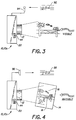
- Figure 3 is a diagrammatical view illustrating use of the camera of Figure 1 to capture a visible image and record sound data.
- Figure 4 is a diagrammatical view illustrating use of the camera of Figure 1 to read invisible printed data on a photographic print and playback recorded sound.
- Figure 5 is a graph of percent maximum transmittance vs. wavelength for an infrared blocking filter suitable for use with the camera of Figure 1.
- Figure 6 is a graph of percent maximum transmittance vs. wavelength for an infrared band pass filter suitable for use with the camera of Figure 1.
- Figure 7 is a semi-diagrammatical view of another embodiment of the camera of the invention.
- Figure 8a is a partial front view of still another embodiment of the camera of the invention. The filter holder is shown in a visible image capture position. The secondary filter mount is shown in a close-up filter position.
- Figure 8b is the same view as Figure 8a, except the secondary filter mount is in a normal lens position. The filter holder is shown in the visible image capture position.
- Figure 8c is the same view as Figure 8a, except the filter holder is in a data-reading position. The secondary filter mount is in the close-up filter position.
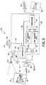
- Figure 9 is a diagrammatical view showing use of another embodiment of the camera of the invention to read invisible printed data on a photographic print and playback recorded sound.
-
- The data-reading
image capture apparatus 10 is a camera, scanner, or other imager that has anexposure system 12 that can capture both a visible radiation image and a second image, separate from the visible radiation image. The captured second image is invisible; that is, the second image is formed by radiation in a band outside the visible spectrum. The second image is reflection, transmission, or luminance from an invisible layer that overlies a visible image. The visible image can be limited to an underlying substrate without information content, but ordinarily would be printed information, in the form of pictorial information, text or other alphanumeric information, or non-alphanumeric indicia. The nature, content, and manner of preparation of the printed image is not critical. The invisible layer can simply be a pictorial image or indicia, but is preferably in the form of a data encodement. For convenience, the capture of the invisible second image is also sometimes referred to herein by the term, "data reading" and similar terms. For example, a camera of the invention can be used to both photograph a subject and to read data invisibly imprinted on a photograph print. (This is illustrated in Figures 4 and 9 as asheet 14 bearing a visible printedimage 16 of a pair of trees. The word "DATA" appears in dashed lines, to represent theinvisible encodement 18.) The data in the encodement can include subject specific information, such as sound recorded when the picture was taken, for playback at the time of viewing the photographic print or other use. The form of the encoded data is not critical to the invention. For example, the encodement can be in accordance with Standard PDF 417 and the L549042D Scanner System marketed by Symbol Technologies, Inc., of Holtsville, New York; or the encodement scheme marketed as Paper Disk by Cobblestone Software, Inc., of Lexington, Massachusetts. - The invention is discussed herein generally in terms of a
camera 10, that is, a portable general purpose image capturing apparatus; but it will be understood that equivalent features are intended for other data-reading image capture apparatus, such as flatbed and media transport scanners. The invention is also discussed herein generally in terms of a visible radiation image and an invisible encodement. The visible image can include a small percentage of invisible radiation (also referred to herein as an "invisible component"). Similarly, the invisible encodement is preferably fully invisible under ordinary viewing conditions, but can include a small percentage of visible radiation (also referred to herein as a "visible component"). An invisible component of the visible image is inconsequential unless the component is in the same radiation band as the invisible encodement. In that case, the invisible component can act as background noise and reduce the signal to noise ratio of the invisible encodement. The amplitude of the invisible component should be insufficient to measurably degrade a digital image produced from the invisible encodement when the invisible encodement is read. Any visible component of the invisible encodement should, preferably, be imperceptible to the viewer under ordinary viewing conditions; but slight degradation of the image may be acceptable under some conditions. - The invisible encodement can absorb the invisible radiation or can reflect and/or emit the invisible radiation. The frequency range or ranges of the invisible radiation is dependent upon the characteristics of the material used for the invisible encodement. Depending upon the material, infrared radiation or ultraviolet radiation or both can be used. High frequency ultraviolet radiation and radiation of higher frequency is not preferred in current embodiments for reasons of safety. Infrared radiation is preferred over ultraviolet for the same reason.
- Referring now to Figures 1-2, the camera 10a includes the
exposure system 12, abody 20 supporting theexposure system 12, and a control interface accessible from the outside of thebody 20 for controlling theexposure system 12. The control interface includes ashutter button 22. Theexposure system 12 includes a capture unit 24 and an optical system 26 (illustrated in Figures 1-2 as a circle) that focuses electromagnetic radiation on the capture unit 24. - The capture unit 24 includes a
digital image detector 28 that is sensitive to a band of visible radiation and a band of invisible electromagnetic radiation. Thedigital image detector 28 is used to capture the invisible second image. Thedigital image detector 28 comprises one or more radiation-sensitive electrical devices which convert an impinging radiation beam into a digital image, that is, an electrical signal from which a two dimensional image can be reconstructed. It is currently preferred to use light-sensitive electrical devices that are sensitive to a broad band of radiation including all or most of the visible spectrum and a selected band of invisible radiation. For example, widely available charge coupled devices (CCD's) are sensitive to visible radiation and a broad band of infrared radiation. The light-sensitive electrical device can also be a charge injection device, a photodiode, a CMOS imager, or another type of photoelectric transducer. - The
digital image detector 28 can include one or more two-dimensional light-sensitive electrical devices, or one or more two dimensional arrays of such devices, or one or more one-dimensional arrays of such devices. With one-dimensional arrays, the detector includes means, well known to those of skill in the art, for scanning the incident beam to provide a two-dimensional digital image. Two-dimensional devices are preferred over one dimensional devices and the use of single discrete devices is currently preferred over the use of arrays of smaller devices for reasons of image quality and ease of assembly. It is well known in the art to use a single two-dimensional capture device with a pixellated three-color filter for color visible image capture. It is also well known to use three two-dimensional devices with a beam splitter and individual colored filters. The use of the single two-dimensional capture device is preferred for reasons of economy. An example of a suitabledigital image detector 28 comprises a single CCD, such as a charge coupled device marketed by Eastman Kodak Company of Rochester, New York as Model No. KAF-6300. Lower resolution digital image detectors can also be used, such as a VGA (video graphics array) sensor having a resolution of 640 by 480 pixels. If desired, the camera of the invention can be prepared by modifying an existing digital camera, such as a DCS-210, marketed by Eastman Kodak Company of Rochester, New York, to add a filter holder (described in detail below). - The
digital image detector 28 can be used for capture of the visible image. In this case, thedigital image detector 28 is utilized for visible image capture in the same manner as in the various digital cameras well known to those of skill in the art. Alternatively, a visibleimage capture component 30 can be used. The visibleimage capture component 30 can be digital, using the same kinds of components as previously described for thedigital image detector 28; or can utilize photographic film, as shown in Figure 7. Suitable photographic film camera features, such as exposure, film metering, and film transport mechanisms, are well known to those of skill in the art. - The
exposure system 12 of thecapture apparatus 10 includes an image separator 32, for separating the visible light and invisible radiation images. The image separator 32 can be in the form of one or more digital computer programs or subroutines (hereafter "software"), or can be limited to physical features of thecapture apparatus 10, such as optical filters, or can combine physical features and software. Depending upon intended usage, the image separator 32 can switch automatically between visible image capture and data reading states or can be selectively alternated by the user. For the camera 10a, selective alternation by the user is preferred. The manner of alternating the states is not critical, but should not interfere with usage of thecapture apparatus 10 in either state. For example, optical filters can be alternated by detachment and reattachment or, more preferably, by use of any of a wide variety of linear and rotary motion mechanisms to move the filters. - In the camera of Figure 7, the image separator 32 is a mirror that, in a first position 32a (indicated by solid lines), directs light to the
digital image detector 28; and, in asecond position 32b (indicated by dashed lines), directs light to photographic film or digital visibleimage capture component 30. Suitable mirror mechanisms are well known to those of skill in the art, since similar mirror mechanisms are used in single lens reflex cameras. A fixed half-silvered mirror could also be used. The image separator 32 of Figure 7 is not preferred since it is relatively complex and requires separate invisible and visiblelight detectors - In another embodiment of the invention, the image separator 32 uses one or more optical filters. This approach is simple and relatively inexpensive and is therefore currently preferred. Referring to Figures 1 and 2, in order to separate out the invisible image, the image separator 32 includes a
data filter 36 attenuative for the band of visible radiation to which thedigital image detector 28 is sensitive and transmissive for the band of invisible radiation. The image separator 32 also includes animage filter 38 attenuative for the band of invisible radiation and transmissive for the band of visible radiation. If the band of invisible information is infrared, then the data filter 36 is an infrared bandpass filter and theimage filter 38 is an infrared blocking filter. Simplified absorption spectra for an infrared blocking filter and an infrared bandpass filter are shown in Figures 5 and 6, respectively. Examples of suitable optical filters are an infrared blocking filter, Model No. 58893, marketed by Oriel Corporation of Stratford, Connecticut) and infrared bandpass filter, Model No. 54020, also marketed by Oriel Corporation. - The image and data filters 36,38 are interposed in operative relation to the
detector 28, alternately, for visible image capture and data reading, respectively. Theimage filter 38 can be optional if thecapture component 30 uses photographic film for visible image capture; since ordinary color and black-and-white photographic films, under most conditions, do not absorb well outside the visible spectrum. Under some conditions, such as with high intensity ultraviolet exposure or infrared exposure and infrared film; the use of animage filter 38 would be required or highly desirable. - Referring to the embodiments shown in Figures 1-2, image and data filters 36,38 are each fixed to a
filter holder 40 and are pivoted back and forth about an axis, by anactuator 42, such as a servomotor or mechanical linkage or lever arm. The camera 10a includes anexternal selector 44 that is operatively connected to the actuator 42 (such as, wired in an appropriate circuit for the servomotor or physically joined) to move thefilter holder 40 between image capture and data reading positions. - The camera or other
image capture apparatus 10 can include a variety of other features for convenience and ease of use. Many cameras have a lens that does not focus well in the distance range which is likely to be used for data reading. In such a camera 10a, a close-up filter 46 (sometimes referred to as a "close-up lens") shown in Figures 8a-8c, can be provided so as to be interposable in the optical system (illustrated in Figures 8a-8c by a cross indicating the position of the optical axis 26a) in tandem with the data filter 36. The close-upfilter 46 can be fixed to the data filter 36 or can be mounted so as to be required for use of the data filter 36 and optional with theimage filter 38. Referring to Figures 8a-8c, afilter holder 40 includes theimage filter 38 and the data filter 36. Thefilter holder 40 is mounted to thecamera body 20 and is movable between an upper position and a lower position, as indicated by double-headedarrow 48, in Figures 8a and 8c, to alternately interpose theimage filter 38 and data filter 36 in theoptical system 26 of the camera 10a. Afilter mount 50 is also joined to thebody 20. Thefilter mount 50 is movable, perpendicular to the directions of motion of thefilter holder 40, between left and right positions. In the left position, a close-upfilter 46, mounted on thefilter mount 50, is interposed in theoptical system 26. In the right position, anormal window 52 is disposed over theoptical system 26. Thenormal window 52 allows theoptical system 26 to function in a "normal" mode (subject matter at a moderate to long focusing distance). Thenormal window 52 can be an opening or can be part of theoptical system 26, that is, a "normal" lens, or can be an accessory, such as a protective window, an auxiliary filter (such as a sky or ultraviolet blocking filter) or the like. Thefilter mount 50 includes astop 54 that allows use of the data filter 36 with the close-upfilter 46, but prevents use of the data filter 36 without the close-upfilter 46. (Blocked motions of thefilter holder 40 and filter mount 50 are indicated by crossed-out double headedarrows stop 54 does not prevent use of thevisible image filter 38 with either the close-upfilter 46 or thenormal window 52. This permits the use of camera 10a to capture normal distance and close-up pictorial images. The camera 10a can also capture visible barcodes and the like, using thevisible image filter 38 and close-upfilter 46. - The camera 10a can include an invisible
radiation illumination source 60 for the band of invisible electromagnetic radiation, such as an infrared illuminator. The camera 10a can also include a visiblelight illumination source 62 for the visible image, such as a flash unit. A wide spectrum illuminator can be used instead ofseparate sources illumination source 60 usable for data capture is a commonly available infrared emitter with a peak wavelength at 880 nm, such as Part No. MTE2050-OH1 marketed by MarkTech Optoelectronics of Latham, New York. The camera or otherimage capture apparatus 10 can have a wide variety of other features present in known cameras and other capture apparatus. - Figure 9 illustrates features and use of another embodiment of the camera 10a that includes a digital image separator 32. The image separator 32 includes a
selector 44 that can be manually alternated (illustrated by double-headed arrow 64) by the user to change the image separator 32 between visible image capture and data reading states. For data reading, the user first switches to the appropriate state and then points the camera 10a at the target, that is, thevisible image 16 bearing theinvisible encodement 18. This is done under ordinary lighting conditions of daylight or ordinary artificial illumination or some combination of the two. Acontroller 66 of a control andprocessing unit 68 receives a status signal from the selector 44 (via by control line 70) and changes to the respective state.Controllers 66 in the form of microprocessors and other components of the control andprocessing unit 68 are well known to those of skill in the art. - The user then actuates the camera 10a. The shutter button 22 (shown in Figures 1-2) can be used to actuate the camera 10a or a separate button or switch (not shown) can be used to actuate the camera 10a in the data reading state, if desired. The
controller 66, in response to the actuation, actives an invisibleradiation illumination source 60 and causes thedigital image detector 28 to capture an image of the target (symbolized in Figure 9 by a broad arrow 71) in a combination of the supplied invisible radiation and ambient lighting 72 (symbolized in Figure 9 by a sun symbol.). The resulting extended spectrum image is stored in afirst memory unit 74. Before or after this capture, thecontroller 66 causes thedigital image detector 28 to capture anotherimage 71 of the target, while the invisibleradiation illumination source 60 is deactivated. The resulting visible light only image is stored in asecond memory unit 76. These two capture events are illustrated in Figure 9 by pairs of paths, each labelled "A" and "B" to sources of illumination and to and from memory storage units.Control lines 82 from thecontroller 66 link to switches 84 (logical or physical or a combination) for the alternative paths A and B. - The extended spectrum and visible light images are combined in a
processor 78. Theprocessor 78 can be subject to acommon controller 66 via acontrol line 86. The visible light only image is subtracted from the extended spectrum image to provide an invisible radiation image which is processed as necessary to retrieve encoded information, and output. (Thedata output 88 is symbolized as a series of musical notes.) A digitized visible light image 90 (indicated by dashed lines) is also available and can be processed and output as desired. For visible image capture, theselector 44 is changed to the "B" position and only the "B" capture and processing path is utilized to provide a visible lightonly image 90. - The digital image separator 32 is preferably used under conditions in which there is little invisible radiation in the ambient visible lighting. Under such conditions, an advantage in signal to noise ratio can be provided, relative to optical filters.
- The camera 10a is used by first selecting for data reading or photography and adjusting the
selector 44 to the appropriate state. When the visible image state is selected, the camera 10a is used for photography and, if desired, for recording of non-image data. Following capture, the captured image or images are processed (chemically or digitally) and visible depictions of captured visible light images are printed (optically or digitally). An invisible encodement of data, secondary to the visible image; can be printed on the photographic print. Since the encodement is invisible, all or part of the encodement can overlie the printed image. In the embodiment shown in Figures 3-4, sound or other input 92 (symbolized as a series of musical notes) is recorded contemporaneously with picture taking, using a microphone orother input device 94, such that an invisible encodement of the sound can be printed on the front surface of a resulting photographic print. - When the data reading camera state is selected from the alternatives of the visible image state and the data reading camera state, the camera 10a is configured to admit invisible radiation in a preselected band and filter out visible radiation. The
invisible encodement 18 is illuminated with a beam of invisible radiation. Theencodement 18 modulates the beam producing a transmitted or reflected image of the encodement, which is digitally photographed. The resulting digital image is processed by an output system resulting in a unit of digital data. The manner of processing to produce and later utilize the digital data is not critical to the invention. The output system can store the processed digital data, or transmit the digital data in some manner to a sound system orother output device 96 to playback all or part of the processed digital data to the user, or provide some combination of these functions, on an immediate or delayed basis. (Playback is illustrated in Figures 4 by a symbol in the form of a series of musical notes.) Components to provide any or all of these functions are well known to those of skill in the art. For example, decodement methods and components are available for the encodement schemes previously mentioned. - The separation of digital data processing from storage, transmission, and display; is a matter of logical convenience in this explanation. It will be understood that digital data processing need not be limited to a single component and processing, control, storage, transmission, and display functions can be supplied by a variety of equipment in a variety of manners. For example, in the embodiments shown in Figures 3-4, the digital data is played back by a digital sound playback system through a speaker. Other audio or visual or textual information can be played back or displayed in a similar manner. The digital data can be used for control or archival purposes. Multiple uses can be made of the same unit of digital data.
Claims (10)
- A data-reading image capture apparatus comprising:a digital image detector sensitive to a band of visible radiation and a band of invisible electromagnetic radiation;an optical system focusing said bands of electromagnetic radiation on said image detector;an image separator disposed in operative relation to said digital image detector and said optical system, said image separator being switchable between an image capture state and a data reading state, said image separator being attenuative for said band of invisible radiation and transmissive for said band of visible radiation in said image capture state, said image separator being attenuative for said band of visible radiation and transmissive for said band of invisible radiation in said data reading state.
- The capture apparatus of claim 1 wherein said image separator further comprises:an image filter attenuative for said band of invisible radiation and transmissive for said band of visible radiation; anda data filter attenuative for said band of visible radiation and transmissive for said band of invisible radiation;said image and data filters being separately interposable in operative relation to said detector, for image capture and data reading, respectively.
- The capture apparatus of claim 1 or 2 wherein said filters are optical filters alternately interposable in said optical system.
- The capture apparatus of claim 1, 2, or 3 further comprising a close-up filter interposable in said optical system in tandem with said data filter.
- The capture apparatus of claim 1 or 2 wherein said digital image detector outputs an imaging signal and said data filter further comprises a digital filter operative on said imaging signal and wherein said exposure system further comprises an image filter attenuative for said band of invisible radiation and transmissive for said band of visible radiation, said image and data filters being separately operative on said imaging signal, for visible image capture and data reading, respectively.
- A method of using a data-reading camera, comprising the steps of:selecting an invisible radiation camera state from alternative visible image and invisible image camera states;illuminating an invisible printed encodement with a beam of invisible radiation to produce an encodement image, said radiation being within a band subject to modulation by said printed encodement;digitally capturing said encodement image during said illuminating to produce a digital image;filtering visible light from at least one of said encodement image and said digital image; andprocessing said digital image of said encodement.
- The method of claim 6 further comprising the steps of:selecting a visible image camera state from alternative visible image and invisible image camera states;photographing a visible light image;recording secondary data.
- The method of claim 7 wherein said first photographing step further comprises digitally photographing said image of said encodement.
- The method of claim 6, 7, or 8 wherein said processing further comprises decoding said encodement.
- The method of claim 9 wherein said data is digitized sound and said method further comprises playing back said sound.
Applications Claiming Priority (2)
| Application Number | Priority Date | Filing Date | Title |
|---|---|---|---|
| US97975 | 1987-09-17 | ||
| US09/097,975 US6700613B1 (en) | 1998-06-16 | 1998-06-16 | Data-reading image capture apparatus, camera, and method of use |
Publications (2)
| Publication Number | Publication Date |
|---|---|
| EP0966149A2 true EP0966149A2 (en) | 1999-12-22 |
| EP0966149A3 EP0966149A3 (en) | 2001-11-07 |
Family
ID=22266010
Family Applications (1)
| Application Number | Title | Priority Date | Filing Date |
|---|---|---|---|
| EP99201797A Withdrawn EP0966149A3 (en) | 1998-06-16 | 1999-06-05 | Data-reading image capture apparatus, camera, and method of use |
Country Status (3)
| Country | Link |
|---|---|
| US (1) | US6700613B1 (en) |
| EP (1) | EP0966149A3 (en) |
| JP (1) | JP2000032306A (en) |
Cited By (1)
| Publication number | Priority date | Publication date | Assignee | Title |
|---|---|---|---|---|
| EP1575266A1 (en) | 2004-03-10 | 2005-09-14 | Samsung Electronics Co., Ltd. | Camcorder filter mechanism |
Families Citing this family (18)
| Publication number | Priority date | Publication date | Assignee | Title |
|---|---|---|---|---|
| GB9813855D0 (en) * | 1998-06-27 | 1998-08-26 | Univ Derby | Image recording apparatus |
| US6791619B1 (en) * | 1998-09-01 | 2004-09-14 | Fuji Photo Film Co., Ltd. | System and method for recording management data for management of solid-state electronic image sensing device, and system and method for sensing management data |
| JP3554703B2 (en) * | 2000-10-12 | 2004-08-18 | リバーベル株式会社 | Information terminal equipment |
| US20020171754A1 (en) * | 2001-05-18 | 2002-11-21 | I-Jen Lai | Digital camera with multi-illuminating source |
| US7307661B2 (en) * | 2002-06-26 | 2007-12-11 | Vbk Inc. | Multifunctional integrated image sensor and application to virtual interface technology |
| JP2005094417A (en) * | 2003-09-18 | 2005-04-07 | Sony Corp | Imaging apparatus |
| US20050265423A1 (en) * | 2004-05-26 | 2005-12-01 | Mahowald Peter H | Monitoring system for cooking station |
| KR100682898B1 (en) * | 2004-11-09 | 2007-02-15 | 삼성전자주식회사 | Imaging apparatus using infrared ray and image discrimination method thereof |
| US8020770B2 (en) | 2005-09-07 | 2011-09-20 | International Business Machines Corporation | Display method and display apparatus |
| US7307552B2 (en) * | 2005-11-16 | 2007-12-11 | Cisco Technology, Inc. | Method and apparatus for efficient hardware based deflate |
| JP2008152032A (en) * | 2006-12-18 | 2008-07-03 | Smk Corp | Camera module |
| CN101650521A (en) * | 2008-08-13 | 2010-02-17 | 深圳富泰宏精密工业有限公司 | Portable communication device |
| US8848059B2 (en) * | 2009-12-02 | 2014-09-30 | Apple Inc. | Systems and methods for receiving infrared data with a camera designed to detect images based on visible light |
| JP2011199798A (en) * | 2010-03-24 | 2011-10-06 | Sony Corp | Physical information obtaining apparatus, solid-state imaging apparatus, and physical information obtaining method |
| TW201137388A (en) * | 2010-04-29 | 2011-11-01 | Lumos Technology Co Ltd | Microscopic spectrum apparatus and image capture apparatus with microscopic spectrum function |
| WO2013055493A1 (en) | 2011-10-11 | 2013-04-18 | Eastman Kodak Company | Compact viewer for invisible indicia |
| US8653445B2 (en) | 2011-10-11 | 2014-02-18 | Eastman Kodak Company | Method for viewing invisible indicia |
| US9939130B2 (en) * | 2013-03-15 | 2018-04-10 | Varian Medical Systems, Inc. | Marker system with light source |
Citations (7)
| Publication number | Priority date | Publication date | Assignee | Title |
|---|---|---|---|---|
| US4415245A (en) * | 1982-05-17 | 1983-11-15 | Eastman Kodak Company | Movable infrared filter for an auto ranging camera |
| US4572625A (en) * | 1983-05-17 | 1986-02-25 | Contraves Ag | Optical system for a sighting device |
| JPS61273091A (en) * | 1985-05-28 | 1986-12-03 | Canon Inc | Video camera |
| JPS6469166A (en) * | 1987-09-10 | 1989-03-15 | Sony Corp | Video movie capable of infrared-photographing |
| JPH0388481A (en) * | 1989-08-30 | 1991-04-12 | Sumitomo Metal Mining Co Ltd | Halation prevention ccd camera equipment |
| JPH03198483A (en) * | 1989-12-27 | 1991-08-29 | Nissan Motor Co Ltd | Image pickup device for vehicle |
| JPH10112816A (en) * | 1996-08-13 | 1998-04-28 | Sony Corp | Video camera having infrared av transmission function |
Family Cites Families (42)
| Publication number | Priority date | Publication date | Assignee | Title |
|---|---|---|---|---|
| US3416426A (en) | 1966-09-29 | 1968-12-17 | Polaroid Corp | Photographic apparatus with rangefinder-aperture control |
| US3666946A (en) | 1970-09-29 | 1972-05-30 | Ncr Co | Automatic information reading system using photoluminescent detection means |
| US4452843A (en) | 1980-05-30 | 1984-06-05 | Gao Gesellschaft Fur Automation Und Organisation Mbh. | Security paper |
| US4603262A (en) | 1983-08-22 | 1986-07-29 | Optel Systems Inc. | Optical device for detecting coded symbols |
| US4652750A (en) | 1983-08-22 | 1987-03-24 | Optel Systems Inc | Optical device for detecting coded symbols |
| US5668364A (en) | 1985-02-28 | 1997-09-16 | Symbol Technologies, Inc. | Target finder in electro-optical scanners |
| US5468949A (en) | 1985-02-28 | 1995-11-21 | Symbol Technologies, Inc. | Portable laser diode scanning head |
| US4679068A (en) * | 1985-07-25 | 1987-07-07 | General Electric Company | Composite visible/thermal-infrared imaging system |
| GB2189800B (en) | 1986-04-07 | 1990-03-14 | Michael Anthony West | Marking of articles |
| US4820911A (en) | 1986-07-11 | 1989-04-11 | Photographic Sciences Corporation | Apparatus for scanning and reading bar codes |
| US4914460A (en) | 1987-05-29 | 1990-04-03 | Harbor Branch Oceanographic Institution Inc. | Apparatus and methods of determining distance and orientation |
| US5841121A (en) | 1988-08-31 | 1998-11-24 | Norand Technology Corporation | Hand-held optically readable character set reader having automatic focus control for operation over a range of distances |
| JPH0236825U (en) | 1988-09-02 | 1990-03-09 | ||
| US5486944A (en) | 1989-10-30 | 1996-01-23 | Symbol Technologies, Inc. | Scanner module for symbol scanning system |
| US4983817A (en) | 1989-03-01 | 1991-01-08 | Battelle Memorial Institute | Background compensating bar code readers |
| US5059126A (en) | 1990-05-09 | 1991-10-22 | Kimball Dan V | Sound association and learning system |
| EP0488177A3 (en) | 1990-11-27 | 1992-07-01 | Matsushita Electric Industrial Co., Ltd | Bar code system |
| US5212371A (en) | 1991-03-01 | 1993-05-18 | Psc, Inc. | Hand held bar code scanner with improved aiming means |
| US5378883A (en) | 1991-07-19 | 1995-01-03 | Omniplanar Inc. | Omnidirectional wide range hand held bar code reader |
| US5142299A (en) | 1991-10-15 | 1992-08-25 | Braun Photo-Aquatic Systems | Hand held system for close-range underwater photography composing and focusing |
| US5314336A (en) | 1992-02-07 | 1994-05-24 | Mark Diamond | Toy and method providing audio output representative of message optically sensed by the toy |
| US5852803A (en) | 1992-03-20 | 1998-12-22 | Chips International, Inc. | Apparatus, system and method for recording and/or retrieving audio information |
| US5289220A (en) | 1992-12-28 | 1994-02-22 | Polaroid Corporation | Detachable close-up lens assembly for an adjustable focus lens camera incorporating a photoranging system |
| US5591955A (en) | 1993-05-11 | 1997-01-07 | Laser; Vadim | Portable data file readers |
| US5710834A (en) | 1995-05-08 | 1998-01-20 | Digimarc Corporation | Method and apparatus responsive to a code signal conveyed through a graphic image |
| SE502177C2 (en) * | 1993-12-16 | 1995-09-04 | Celsiustech Electronics Ab | View including an IR camera |
| JP3244371B2 (en) | 1993-12-22 | 2002-01-07 | オリンパス光学工業株式会社 | Audio information processing system and audio information processing method |
| US5448323A (en) | 1993-12-23 | 1995-09-05 | Polaroid Corporation | Close-up lens assembly incorporating a photo-ranging system |
| US5459317A (en) * | 1994-02-14 | 1995-10-17 | Ohio University | Method and apparatus for non-invasive detection of physiological chemicals, particularly glucose |
| US5781236A (en) * | 1994-03-04 | 1998-07-14 | Canon Kabushiki Kaisha | Image sensing apparatus and image sensing method |
| US5598007A (en) | 1994-03-21 | 1997-01-28 | Intermec Corporation | Symbology reader with fixed focus spotter beam |
| US5550364A (en) | 1994-03-21 | 1996-08-27 | Intermec Corporation | Method and apparatus for spotter beam formation using a partitioned optical element |
| TW280893B (en) | 1994-05-06 | 1996-07-11 | Kansai Paint Co Ltd | |
| US5678098A (en) * | 1994-06-09 | 1997-10-14 | Fuji Photo Film Co., Ltd. | Method and apparatus for controlling exposure of camera |
| US5693693A (en) | 1994-12-01 | 1997-12-02 | Pitney Bowes, Inc. | Bar code printing and scanning using wax based invisible fluorescent inks |
| US5525798A (en) | 1994-12-01 | 1996-06-11 | Pitney Bowes Inc. | Bar code scanner for reading a lower layer luminescent invisible ink that is printed below a upper layer luminescent invisible ink |
| US5502304A (en) | 1994-12-01 | 1996-03-26 | Pitney Bowes Inc. | Bar code scanner for reading a visible ink and a luminescent invisible ink |
| AU2243395A (en) | 1995-04-14 | 1996-10-30 | Edwin B. Greene | Negotiable instrument fraud detector and processor |
| JP3316725B2 (en) * | 1995-07-06 | 2002-08-19 | 三菱電機株式会社 | Face image pickup device |
| US5666577A (en) | 1995-08-31 | 1997-09-09 | Eastman Kodak Company | System for switching pointing indices in laser aimed cameras |
| US6041195A (en) * | 1996-07-24 | 2000-03-21 | Minolta Co., Ltd. | Camera capable of video and film shooting having optical viewfinder |
| US5982423A (en) * | 1996-08-13 | 1999-11-09 | Sony Corporation | Video photographing apparatus having infrared rays AV transmitting function |
-
1998
- 1998-06-16 US US09/097,975 patent/US6700613B1/en not_active Expired - Lifetime
-
1999
- 1999-06-05 EP EP99201797A patent/EP0966149A3/en not_active Withdrawn
- 1999-06-07 JP JP11159645A patent/JP2000032306A/en active Pending
Patent Citations (7)
| Publication number | Priority date | Publication date | Assignee | Title |
|---|---|---|---|---|
| US4415245A (en) * | 1982-05-17 | 1983-11-15 | Eastman Kodak Company | Movable infrared filter for an auto ranging camera |
| US4572625A (en) * | 1983-05-17 | 1986-02-25 | Contraves Ag | Optical system for a sighting device |
| JPS61273091A (en) * | 1985-05-28 | 1986-12-03 | Canon Inc | Video camera |
| JPS6469166A (en) * | 1987-09-10 | 1989-03-15 | Sony Corp | Video movie capable of infrared-photographing |
| JPH0388481A (en) * | 1989-08-30 | 1991-04-12 | Sumitomo Metal Mining Co Ltd | Halation prevention ccd camera equipment |
| JPH03198483A (en) * | 1989-12-27 | 1991-08-29 | Nissan Motor Co Ltd | Image pickup device for vehicle |
| JPH10112816A (en) * | 1996-08-13 | 1998-04-28 | Sony Corp | Video camera having infrared av transmission function |
Non-Patent Citations (5)
| Title |
|---|
| PATENT ABSTRACTS OF JAPAN vol. 011, no. 127 (E-501), 21 April 1987 (1987-04-21) & JP 61 273091 A (CANON INC), 3 December 1986 (1986-12-03) * |
| PATENT ABSTRACTS OF JAPAN vol. 013, no. 285 (E-780), 29 June 1989 (1989-06-29) & JP 01 069166 A (SONY CORP), 15 March 1989 (1989-03-15) * |
| PATENT ABSTRACTS OF JAPAN vol. 015, no. 265 (E-1086), 5 July 1991 (1991-07-05) & JP 03 088481 A (SUMITOMO METAL MINING CO LTD), 12 April 1991 (1991-04-12) * |
| PATENT ABSTRACTS OF JAPAN vol. 015, no. 464 (E-1137), 25 November 1991 (1991-11-25) & JP 03 198483 A (NISSAN MOTOR CO LTD), 29 August 1991 (1991-08-29) * |
| PATENT ABSTRACTS OF JAPAN vol. 1998, no. 09, 31 July 1998 (1998-07-31) & JP 10 112816 A (SONY CORP), 28 April 1998 (1998-04-28) * |
Cited By (1)
| Publication number | Priority date | Publication date | Assignee | Title |
|---|---|---|---|---|
| EP1575266A1 (en) | 2004-03-10 | 2005-09-14 | Samsung Electronics Co., Ltd. | Camcorder filter mechanism |
Also Published As
| Publication number | Publication date |
|---|---|
| US6700613B1 (en) | 2004-03-02 |
| EP0966149A3 (en) | 2001-11-07 |
| JP2000032306A (en) | 2000-01-28 |
Similar Documents
| Publication | Publication Date | Title |
|---|---|---|
| US6700613B1 (en) | Data-reading image capture apparatus, camera, and method of use | |
| US5946031A (en) | Electronic still camera with printing capability | |
| US6583811B2 (en) | Photographic system for recording data and reproducing images using correlation data between frames | |
| EP0974924A2 (en) | Data reader and reader system having visible centerless targeting | |
| KR19980064724A (en) | Still camera | |
| US20090268942A1 (en) | Methods and apparatus for detection of motion picture piracy for piracy prevention | |
| US6868231B2 (en) | Imaging using silver halide films with micro-lens capture and optical reconstruction | |
| AU737027B2 (en) | Device for the alternate or simultaneous filming of still and video pictures or multipurpose camera | |
| JPH1039408A (en) | Camera | |
| JPH11258657A (en) | Camera | |
| JPH1195092A (en) | Electronic still camera | |
| JP2003244501A (en) | Electronic camera | |
| JP3748472B2 (en) | Optical equipment | |
| US7424219B2 (en) | Viewfinder system for a digital camera and digital camera provided with such a system | |
| JPH09189934A (en) | Image pickup device | |
| JPH0583477A (en) | Color separation scanner | |
| JP2928864B2 (en) | Photo equipment | |
| KR100573595B1 (en) | digital still camera capable of photographing an image on film and method thereof | |
| JP3515670B2 (en) | Electro-developing recording medium for use in an electro-developing camera and image reading apparatus for reading the recorded image | |
| JP2000013663A (en) | Digital camera | |
| JPH11341503A (en) | Video camera | |
| JP2003307815A (en) | Photographing device, film housing body, film system, laboratory equipment, photographing method and image processing method | |
| JP2000272783A (en) | Image recording sheet holder and image reader to which such holder is applicable | |
| EP0974925A2 (en) | Angled targeting data reader and reading system | |
| JPH03236685A (en) | Electronic still camera with display device |
Legal Events
| Date | Code | Title | Description |
|---|---|---|---|
| PUAI | Public reference made under article 153(3) epc to a published international application that has entered the european phase |
Free format text: ORIGINAL CODE: 0009012 |
|
| AK | Designated contracting states |
Kind code of ref document: A2 Designated state(s): AT BE CH CY DE DK ES FI FR GB GR IE IT LI LU MC NL PT SE Kind code of ref document: A2 Designated state(s): DE FR GB |
|
| AX | Request for extension of the european patent |
Free format text: AL;LT;LV;MK;RO;SI |
|
| PUAL | Search report despatched |
Free format text: ORIGINAL CODE: 0009013 |
|
| AK | Designated contracting states |
Kind code of ref document: A3 Designated state(s): AT BE CH CY DE DK ES FI FR GB GR IE IT LI LU MC NL PT SE |
|
| AX | Request for extension of the european patent |
Free format text: AL;LT;LV;MK;RO;SI |
|
| RIC1 | Information provided on ipc code assigned before grant |
Free format text: 7H 04N 1/00 A, 7G 03B 11/00 B |
|
| 17P | Request for examination filed |
Effective date: 20020418 |
|
| AKX | Designation fees paid |
Free format text: DE FR GB |
|
| 17Q | First examination report despatched |
Effective date: 20040304 |
|
| STAA | Information on the status of an ep patent application or granted ep patent |
Free format text: STATUS: THE APPLICATION IS DEEMED TO BE WITHDRAWN |
|
| 18D | Application deemed to be withdrawn |
Effective date: 20051201 |
|
| R18D | Application deemed to be withdrawn (corrected) |
Effective date: 20060103 |