EP0965710B1 - Fahrzeugsteuerungssystem - Google Patents
Fahrzeugsteuerungssystem Download PDFInfo
- Publication number
- EP0965710B1 EP0965710B1 EP19990304272 EP99304272A EP0965710B1 EP 0965710 B1 EP0965710 B1 EP 0965710B1 EP 19990304272 EP19990304272 EP 19990304272 EP 99304272 A EP99304272 A EP 99304272A EP 0965710 B1 EP0965710 B1 EP 0965710B1
- Authority
- EP
- European Patent Office
- Prior art keywords
- vehicle
- area
- large area
- control system
- detection
- Prior art date
- Legal status (The legal status is an assumption and is not a legal conclusion. Google has not performed a legal analysis and makes no representation as to the accuracy of the status listed.)
- Expired - Lifetime
Links
Images


Classifications
-
- B—PERFORMING OPERATIONS; TRANSPORTING
- B60—VEHICLES IN GENERAL
- B60R—VEHICLES, VEHICLE FITTINGS, OR VEHICLE PARTS, NOT OTHERWISE PROVIDED FOR
- B60R25/00—Fittings or systems for preventing or indicating unauthorised use or theft of vehicles
- B60R25/20—Means to switch the anti-theft system on or off
- B60R25/24—Means to switch the anti-theft system on or off using electronic identifiers containing a code not memorised by the user
- B60R25/245—Means to switch the anti-theft system on or off using electronic identifiers containing a code not memorised by the user where the antenna reception area plays a role
-
- B—PERFORMING OPERATIONS; TRANSPORTING
- B60—VEHICLES IN GENERAL
- B60R—VEHICLES, VEHICLE FITTINGS, OR VEHICLE PARTS, NOT OTHERWISE PROVIDED FOR
- B60R25/00—Fittings or systems for preventing or indicating unauthorised use or theft of vehicles
- B60R25/20—Means to switch the anti-theft system on or off
- B60R25/2036—Means to switch the anti-theft system on or off by using the door logic and door and engine unlock means
-
- B—PERFORMING OPERATIONS; TRANSPORTING
- B60—VEHICLES IN GENERAL
- B60R—VEHICLES, VEHICLE FITTINGS, OR VEHICLE PARTS, NOT OTHERWISE PROVIDED FOR
- B60R25/00—Fittings or systems for preventing or indicating unauthorised use or theft of vehicles
- B60R25/20—Means to switch the anti-theft system on or off
- B60R25/24—Means to switch the anti-theft system on or off using electronic identifiers containing a code not memorised by the user
- B60R25/246—Means to switch the anti-theft system on or off using electronic identifiers containing a code not memorised by the user characterised by the challenge triggering
-
- G—PHYSICS
- G07—CHECKING-DEVICES
- G07C—TIME OR ATTENDANCE REGISTERS; REGISTERING OR INDICATING THE WORKING OF MACHINES; GENERATING RANDOM NUMBERS; VOTING OR LOTTERY APPARATUS; ARRANGEMENTS, SYSTEMS OR APPARATUS FOR CHECKING NOT PROVIDED FOR ELSEWHERE
- G07C9/00—Individual registration on entry or exit
- G07C9/00174—Electronically operated locks; Circuits therefor; Nonmechanical keys therefor, e.g. passive or active electrical keys or other data carriers without mechanical keys
- G07C9/00309—Electronically operated locks; Circuits therefor; Nonmechanical keys therefor, e.g. passive or active electrical keys or other data carriers without mechanical keys operated with bidirectional data transmission between data carrier and locks
-
- E—FIXED CONSTRUCTIONS
- E05—LOCKS; KEYS; WINDOW OR DOOR FITTINGS; SAFES
- E05F—DEVICES FOR MOVING WINGS INTO OPEN OR CLOSED POSITION; CHECKS FOR WINGS; WING FITTINGS NOT OTHERWISE PROVIDED FOR, CONCERNED WITH THE FUNCTIONING OF THE WING
- E05F15/00—Power-operated mechanisms for wings
- E05F15/70—Power-operated mechanisms for wings with automatic actuation
- E05F15/73—Power-operated mechanisms for wings with automatic actuation responsive to movement or presence of persons or objects
- E05F15/76—Power-operated mechanisms for wings with automatic actuation responsive to movement or presence of persons or objects responsive to devices carried by persons or objects, e.g. magnets or reflectors
-
- E—FIXED CONSTRUCTIONS
- E05—LOCKS; KEYS; WINDOW OR DOOR FITTINGS; SAFES
- E05Y—INDEXING SCHEME RELATING TO HINGES OR OTHER SUSPENSION DEVICES FOR DOORS, WINDOWS OR WINGS AND DEVICES FOR MOVING WINGS INTO OPEN OR CLOSED POSITION, CHECKS FOR WINGS AND WING FITTINGS NOT OTHERWISE PROVIDED FOR, CONCERNED WITH THE FUNCTIONING OF THE WING
- E05Y2900/00—Application of doors, windows, wings or fittings thereof
- E05Y2900/50—Application of doors, windows, wings or fittings thereof for vehicles
- E05Y2900/53—Application of doors, windows, wings or fittings thereof for vehicles characterised by the type of wing
- E05Y2900/531—Doors
-
- G—PHYSICS
- G07—CHECKING-DEVICES
- G07C—TIME OR ATTENDANCE REGISTERS; REGISTERING OR INDICATING THE WORKING OF MACHINES; GENERATING RANDOM NUMBERS; VOTING OR LOTTERY APPARATUS; ARRANGEMENTS, SYSTEMS OR APPARATUS FOR CHECKING NOT PROVIDED FOR ELSEWHERE
- G07C9/00—Individual registration on entry or exit
- G07C9/00174—Electronically operated locks; Circuits therefor; Nonmechanical keys therefor, e.g. passive or active electrical keys or other data carriers without mechanical keys
- G07C9/00309—Electronically operated locks; Circuits therefor; Nonmechanical keys therefor, e.g. passive or active electrical keys or other data carriers without mechanical keys operated with bidirectional data transmission between data carrier and locks
- G07C2009/00317—Electronically operated locks; Circuits therefor; Nonmechanical keys therefor, e.g. passive or active electrical keys or other data carriers without mechanical keys operated with bidirectional data transmission between data carrier and locks keyless data carrier having only one limited data transmission range
- G07C2009/00333—Electronically operated locks; Circuits therefor; Nonmechanical keys therefor, e.g. passive or active electrical keys or other data carriers without mechanical keys operated with bidirectional data transmission between data carrier and locks keyless data carrier having only one limited data transmission range and the lock having more than one limited data transmission ranges
-
- G—PHYSICS
- G07—CHECKING-DEVICES
- G07C—TIME OR ATTENDANCE REGISTERS; REGISTERING OR INDICATING THE WORKING OF MACHINES; GENERATING RANDOM NUMBERS; VOTING OR LOTTERY APPARATUS; ARRANGEMENTS, SYSTEMS OR APPARATUS FOR CHECKING NOT PROVIDED FOR ELSEWHERE
- G07C9/00—Individual registration on entry or exit
- G07C9/00174—Electronically operated locks; Circuits therefor; Nonmechanical keys therefor, e.g. passive or active electrical keys or other data carriers without mechanical keys
- G07C2009/00753—Electronically operated locks; Circuits therefor; Nonmechanical keys therefor, e.g. passive or active electrical keys or other data carriers without mechanical keys operated by active electrical keys
- G07C2009/00769—Electronically operated locks; Circuits therefor; Nonmechanical keys therefor, e.g. passive or active electrical keys or other data carriers without mechanical keys operated by active electrical keys with data transmission performed by wireless means
- G07C2009/00793—Electronically operated locks; Circuits therefor; Nonmechanical keys therefor, e.g. passive or active electrical keys or other data carriers without mechanical keys operated by active electrical keys with data transmission performed by wireless means by Hertzian waves
-
- G—PHYSICS
- G07—CHECKING-DEVICES
- G07C—TIME OR ATTENDANCE REGISTERS; REGISTERING OR INDICATING THE WORKING OF MACHINES; GENERATING RANDOM NUMBERS; VOTING OR LOTTERY APPARATUS; ARRANGEMENTS, SYSTEMS OR APPARATUS FOR CHECKING NOT PROVIDED FOR ELSEWHERE
- G07C2209/00—Indexing scheme relating to groups G07C9/00 - G07C9/38
- G07C2209/60—Indexing scheme relating to groups G07C9/00174 - G07C9/00944
- G07C2209/63—Comprising locating means for detecting the position of the data carrier, i.e. within the vehicle or within a certain distance from the vehicle
Definitions
- the present invention relates to a vehicle control system, and particularly to a vehicle control system for controlling a vehicle-mounted device, using a portable transceiver (transmitter/receiver).
- Japanese Patent Laid-open Publication No. Hei 5-71257 discloses an automatic door-lock device which can automatically lock or unlock vehicle doors without a manual operation for locking or unlocking.
- This device referred to as a smart entry system, unlocks a vehicle door when it detects a user coming close to the vehicle, and locks the door when it detects a user going away from the vehicle.
- a dedicated portable transceiver carried by a user receives an ID request signal sent from a vehicle, the transceiver returns a corresponding response ID to the vehicle.
- a vehicle In the above smart entry system, a vehicle must continually send ID request signals to search for a portable transceiver carried by a user.
- ID request signals When a transmission area for the ID request signals is set covering too vast a region, a user approaching the vehicle cannot be easily recognized. For example, a user who only passes near the vehicle may erroneously be understood as a user preparing to enter the vehicle, and the door may erroneously be unlocked before the authorized user reaches the vehicle. This is undesirable in view of crime prevention as it may cause a risk that a third person would get on the vehicle.
- the transmission area can be made smaller to aid accurate determination of whether a user is in fact approaching the vehicle.
- this arrangement is not desirable in terms of control as it may require formation of a number of detection areas using a number of detection means for full-time observation, leading to heavy use of the vehicle's battery.
- the present invention was conceived to overcome the above problems and aims to provide a vehicle control system capable of accurately recognizing approach by a user and controlling a vehicle-mounted device at an optimum timing while suppressing battery consumption.
- a vehicle control system comprising large area ID request means for sending an ID request signal to a portable transceiver present in a specific area around a vehicle to form a large area; ID verification means for receiving a response ID in reply to the ID request signal to conduct verification with the response ID received; area switching means for activating at least one detection means using a detection area smaller than the larger area when the response ID received is verified coincident with a reference ID; and control means for controlling operation of a vehicle-mounted device based on a detection result by the detection means.
- a "large area” represents a detection area with relatively low detection accuracy which is formed having a radius of approximately 10 m with the vehicle at the center.
- a “small area” represents a detection area with high detection accuracy, which is formed in a region close, e.g., within 1 m in radius, to a specific point on the vehicle, such as the driver seat door or a passenger seat door.
- a “vehicle-mounted device” may include a door-lock controller, a lighting controller, an engine starting controller, a driving condition controller, and so on.
- the detection means using a small area is activated after confirmation was made that a user carrying a portable transceiver entered the large area formed around the vehicle, highly accurate detection operation using a small area is carried out only when the user has approached sufficiently close to the vehicle. That is, as such detection, which consumes a relatively large amount of battery power, is performed only in the case where the user has approached sufficiently close to the vehicle, wasteful consumption of battery power can be suppressed.
- highly accurate detection is carried out using a small area, approaching state of a user to the vehicle can be highly accurately detected. As a result, the vehicle-mounted device can be controlled at the optimum timing.
- control means may control a door-lock controller for controlling locking/unlocking operation with respect to doors of the vehicle.
- control means also locks the door in response to a user carrying a portable transceiver going away from the large area.
- the large area ID request means may form a first large area and a second large area in lateral directions with respect to the vehicle on a driver side and a passenger side , respectively, at a predetermined timing, and the area switching means activates individually at least one detection area formed either on the driver side or the passenger side of the vehicle, based on a response ID sent from a portable transceiver having entered at least one of the first large area or the second large area.
- the large area ID request means may form the first and second large areas either at the same or different timing.
- wasteful battery consumption can be further reduced.
- preparation for, and execution of, door-unlocking operation is applied only to the doors on the side with an approaching user, intrusion by the third person to the vehicle through the doors on the other side can be prevented for improved security.
- formation of the first and second large areas at different timing can further reduce wasteful battery consumption.
- the detection means may be small area ID request means for sending an ID request signal which is different from the ID request signal to be sent to the large area, and the control means controls operation of the vehicle-mounted device when the ID verif ication means verifies that a response ID in reply to the ID request signal sent from the small area ID request means coincides with a reference ID.
- the detection means may be a body detection sensor for detecting an approaching vehicle user.
- body detection sensor may include a photo-sensor or any other sensor which can detect, for example, a user's hand extended to the door knob because the user intends to opening the door, based on a changing gain of the antenna incorporated into, for example, the door knob.
- the above vehicle control system may further comprise operation area selection means for selectively activating one detection means, the one being associated with a specific location.
- specific detection means associated with a specific location indicates detection means for detecting approach by a user or a portable transceiver to, for example, the driver seat door.
- the detection means can perform minimum detection so as not to impede a user's smooth entry to the vehicle, even when the battery is left less than a predetermined amount. With this arrangement, the function of the vehicle control system can be utilized while reducing battery consumption.
- the above vehicle control system may further comprises area changing means for changing a transmission area for the ID request signal sent from the small area ID request means.
- a transmission area for an ID request signal from the small ID request means can be desirably determined. That is, with a small transmission area, excessive user detection will be prevented when, for example, the vehicle is in a narrow space, such as in a garage, leaving little space around the vehicle and the user may have to pass near the vehicle even when he does not intend to get on the vehicle. An approaching user can be accurately recognized and his intention of getting on the vehicle can be precisely confirmed. On the other hand, with a large transmission area, control over the vehicle-mounted device can be begun at an early stage.
- the area switching means suspends operation of detection means associated with an unlocked door.
- the above vehicle control system may further comprise driven state detection means for detecting a driven state of the vehicle, and operation suspension means for suspending operation of the large area ID request means and the detection means while driven state of the vehicle is kept detected.
- the large area ID request means may send a wake-up signal at a predetermined interval for detecting whether or not a portable transceiver is present around the vehicle, and forms the first large area and the second large area based on a predetermined priority order when presence of the portable transceiver is confirmed.
- a "wake-up signal" may preferably be transmitted at a relatively long interval, such as, for example, 300 msec.
- Fig. 1 is a schematic diagram showing detection areas formed by a vehicle control system according to a first embodiment of the present invention, to detect a user (i.e., a portable transceiver (transmitter/receiver) 12 carried by a user) approaching a vehicle 10.
- a user i.e., a portable transceiver (transmitter/receiver) 12 carried by a user
- the first embodiment is characterized by the fact that detection area consists of a large area 14 and a plurality of small areas 16a-16f.
- the large area 14 is formed with the vehicle 10 at a center, while a plurality of (six in the first embodiment description) small areas 16a-16f, each being smaller than the large area 14, are formed around the vehicle 10.
- the large area 14 and the small areas 16a-16f are switched for use, depending on the approaching state of a portable transceiver 12 to the vehicle 10, for accurate detection of approach of the portable transceiver 12 (i.e., the user).
- the large area 14 is, for example, a substantially circular detection area formed with the vehicle 10 at the center and may have a radius of, for example, 10 m.
- the large area 14 is an area reachable for a large area signal, a signal carried by an electric wave of a high frequency (e.g., an order of a few hundreds MHz).
- a portable transceiver 12 in the large area 14 is detected by the vehicle-side system recognizing a response signal sent from the transceiver 12 in reply to a large area signal.
- the small areas 16a-16f each are, for example, a substantially round detection area formed having a 1 m radium, and, specifically, is an area reachable for a small area signal, a signal carried by an electric wave of a low frequency (e.g., an order of a few KHz).
- a portable transceiver 12 having entered any of the small areas 16a-16f is detected by the vehicle-side system recognizing a response signal sent from the transceiver 12 in response to a small area signal, and the vehicle-mounted device is then controlled.
- Fig. 2 is a conceptual diagram schematically showing a structure of a vehicle-side system 18 of the vehicle control system according to the first embodiment.
- the vehicle-side system 18 includes a first transmitter 20, a second transmitter 22, a receiver 24, and a controller 26, the former three being connected to the controller 26.
- the first transmitter 20 sends, as a large area signal, a large area ID request signal containing a predetermined ID code.
- the second transmitter 22 sends, as a small area signal, a small area ID request signal containing a predetermined ID code.
- the receiver 24 receives a response signal which is a response ID signal containing a predetermined ID sent from a portable transceiver 12 in reply to a large or small area ID request signal.
- the controller 26 is responsible for comprehensive control over the entire system.
- the first transmitter 20 is connected to a first antenna 20a, installed, for example, at the middle of the roof of the vehicle 10, together constituting a large area ID request means.
- the second transmitter 22 is connected to second to seventh antenna 22a-22f, together constituting a small area ID request means which acts as a detection means.
- the second, third, fifth, and sixth antennas 22a, 22b, 22d, 22e are installed, for example, each on each door, as shown in Fig. 1, and the fourth and seventh antennas 22c, 22f are installed near the rear and front bumpers, respectively.
- the receiver 24 is connected to an eighth antenna 24a, which may be installed at a desired point on the vehicle 10. Note that each antenna has a size and shape which do not damage the vehicle 10 design, and is installed on a desired point on the vehicle 10 such that they do not hamper the functions of the vehicle 10.
- the controller 26 is also connected to a memory 28, which comprises a ROM or the like.
- the memory 28 stores reference IDs to be compared for verification with response IDs, the response IDs being sent from a portable transceiver 12 in reply to a large or small area ID request signal sent thereto by the first or second transmitter 20 or 22.
- the controller 26 is further connected to a vehicle-mounted device, such as a door lock controller 30, and controls the device when it recognizes an approaching portable transceiver 12 (i.e., the user) based on a signal received by the receiver 24.
- a vehicle-mounted device may include a lighting controller, an engine starting controller, and a driving condition controller for optimum steering and/or sheet positions for each user).
- the receiver 24, the eighth antenna 24a, the controller 26, the memory 28, and so on together constitute an ID verification means.
- the controller 26 includes an area switching means for activating detection means using small areas 16a-16f as a detection area when a response ID is verified to coincide with a reference ID.
- Fig. 3 is a block diagram showing a structure of the portable transceiver 12.
- the portable transceiver 12 is incorporated into, for example, the grip of an ignition key, a key holder which can be easily attached to ignition or other keys, or the like.
- the portable transceiver 12 has a structure including an electric control unit (ECU) 32 as a major component.
- the ECU 32 is connected to a first detector 36, a second detector 40, and a transmitter 42.
- the first detector 36 is also connected to a first antenna 34 for receiving a large area ID request signal
- the second detector 40 is also connected to a second antenna 38 for receiving a small area ID request signal.
- the transmitter 42 is also connected to a third antenna 44 for, via which, sending a response ID signal in reply to a large or small area ID request signal.
- the ECU 32 is further connected to a memory 46 for storing response ID signals to be read therefrom when needed.
- a larger area 14 is an area reachable for an electric wave carrying a large area ID request signal, as described above, and formed using electric waves of small power and a high frequency (e.g., approximately 300 MHz) which can create a detection area dimly covering a relatively large region.
- a high frequency e.g., approximately 300 MHz
- the ECU 32 When a user with a portable transceiver 12 enters the large area 14, and the first detector 36 of the portable transceiver 12 receives, via the first antenna 34, a large area ID request signal, the ECU 32 immediately reads a corresponding response ID from the memory 46, and sends the response ID signal via the transmitter 42 and the third antenna 44.
- the transmitter 42 uses a transmission frequency of, e.g., 300 MHz.
- the response ID is received via the eighth antenna 24a (whose receiving frequency may be, e.g., 300 MHz) by the receiver 24, and the controller 26 then reads a reference ID for a large area (a reference ID-1) from the memory 26 for comparison with the received response ID (S101).
- the controller 26 suspends operation of the first transmitter 20 (the first antenna 20a), and simultaneously activates, via the second transmitter 22, the second to seventh antenna 22a-22f (S102) to form small areas 16a-16f, as shown in Fig. 1.
- Small areas 16a-17f each are an area reachable for an electric wave carrying a small area ID request signal, as described above, and formed using electric waves of a low frequency (e.g., approximately 125 KHz) which can create a detection area intensively covering a relatively small area.
- a low frequency e.g., approximately 125 KHz
- small area ID request signals are sent individually via associated antennas. Then, when the user carrying a portable transceiver 12 further approaches the vehicle 10, the transceiver 12, particularly the second detector 40 thereof, can receive via the second antenna 38 a small area ID request signal associated with any of the small areas 16a-17f. When any small area ID request signal is received, the ECU 32 immediately reads a response ID corresponding to the received small area ID, from the memory 46, and sends the response ID signal via the transmitter 42 and the third antenna 44.
- the controller 26 compares the received response ID with reference IDs sequentially read from the memory 28 to see with which of the reference IDs the received ID coincides.
- reference ID-2 corresponds to a small area 16a
- reference ID-3 corresponds to a small area 16b
- reference ID-4 corresponds to a small area 16c
- reference ID-5 corresponds to a small area 16d
- reference ID-6 corresponds to a small area 16e
- reference ID-7 corresponds to a small area 16f.
- the received response ID is verified to coincide with reference ID-2 (S103). Then, the number of times when they coincide with each other, or N, is detected.
- N is equal to or more than a predetermined time, e.g., five.
- a predetermined time e.g., five
- N is judged as equal to or more than a predetermined time, e.g., five
- a received response ID is again compared with a reference ID for a small area for verification at S103.
- the detection at S104 proves that the number of times of the coincident N is less than five, whether the user remains in the small area 16a or moved to another small area is then detected.
- a receivable response ID is again compared with a reference ID for a small area for verification at S103.
- the controller 26 determines at S103 that the received response ID does not coincide with a reference ID-2, that response ID is further compared with other reference IDs sequentially read from the memory 28. Provide that the response ID coincides with a reference ID-3 (S106). Then, whether or not the number of times of the coincidence, or N, is equal to or more than a predetermined time, e.g., five, is detected (S107), similar to the case with reference ID-2.
- a predetermined time e.g., five
- ID verification is carried out as above, sequentially using reference ID-4 corresponding to a small area 16c for unlocking a trunk (S109-S111), using a reference ID-5 corresponding to a small area 16d for unlocking door 3 (omitted in the flowchart), using a reference ID-6 corresponding to a small area 16e for unlocking door 4 (omitted in the flowchart), and using a reference ID-7 corresponding to a small area 16f for unlocking a hood (S112-S114).
- the controller 26 When the received response ID does not coincide with any of the reference IDs 2-7, or when the received response ID ceases to so coincide, the controller 26 then detects whether or not any door is unlocked (S115). When no unlocked door is detected, the controller 26 then determines that the user with the portable transceiver 12 approached the vehicle 10 for a purpose other than operation of the vehicle 10, and suspends operation of the second to seventh antennas 22a-22f, thereby halting intensive user-approach detection using many small areas (S116). Instead, the first antenna 20a is activated (S100) thereby resuming rough, large area user-approach detection.
- the controller 26 halts operation of the second to seventh antennas 22a-22f, and activates the first antenna 20a (S117) to send a large area ID request signal for detection of the presence of a portable transceiver 12 (i.e., a user). Then, whether or not a response ID is sent from a portable transceiver 12 in reply to the large.area ID request signal (i.e., a response ID coincident with a reference ID-1), is detected (S118).
- the controller 26 determines that a portable transceiver 12 (i.e., a user) is present within the large area 14 formed surrounding the vehicle 10. After the determination, the controller 26 suspends operation of the first transmitter 20 (the first antenna 20a) and simultaneously activates, via the second transmitter 22, the second to seventh antenna 22a-22f (S102) for accurate location of the portable transceiver 12 (i.e., the user), as described above.
- the controller 26 fails to verify at S118 that the received response ID coincides with a reference ID-1, it is then determined that a portable transceiver 12 (i.e., the user) has moved out of the large area 14, in other words, it has moved away from the vehicle 10.
- the controller 26 then locks any unlocked door, if any, (S120) before processing at S101 and thereafter is repeatedly carried out for detection of a user entering the large area 14.
- the controller 26 selectively switches, according to a user's approach to the vehicle 10, detection areas between a large area for rough detection and small areas for intensive detection using a plurality of detection means for detection of a portable transceiver 12. That is, when a user is away from the vehicle, too intensive detection is not applied so that driving power can be saved thereby reducing battery consumption. Moreover, as approaching state of a portable transceiver 12 (i.e., a user) to a vehicle 10 can be accurately recognized through detection using a small area, a door lock mechanism can be controlled at an optimum timing.
- small areas 16a-16f may be set having a desirable radius, other than the example radius of 1 m used in the above description. This can be achieved through provision of an area changer 26a to the controller 26, which changes a transmission area for a small area ID request signal.
- an area changer 26a to the controller 26, which changes a transmission area for a small area ID request signal.
- a user may pass near the vehicle 10 without an intention of getting on the vehicle 10 in a small parking lot. Under such circumstance, if the door is unlocked when it is unnecessary or door unlocking/locking operation is repeatedly carried out, the user may feel uneasy, and security may be deteriorated. Therefore, in a situation where a user may often pass near the vehicle, the radius of each of the small areas 16a-16f may be set at, for example, 0.5 m or 0.3 m to prevent the above inconvenience.
- an operation area selector 26b may be provided connected to the controller 26, for selectively forming only a specific small area or areas. For example, when the battery of the vehicle 10 is reduced below a predetermine amount level, which is recognized by the controller 26, the operation area selector 26b forms only a predetermined small area or areas. That is, in order to achieve smart-entry control over at least a door needed to be thus controlled, e.g., the door 1 on the driver side, only the small area 16a is automatically formed. With this arrangement, battery consumption can be further reduced. Also, the provision of an operation area selector 26b allows a user to freely and desirably form a small area or areas 16a-16f. This enables controlling of, for example, only the doors on the driver and passenger sides.
- the electric waves from the TV tower may act as disturbance waves on the vehicle control system of the present invention, suppressing the electric waves used in the first embodiment and deteriorating detection sensitivity.
- the controller 26 may be unable to recognize a response ID sent with respect to a large area ID request signal (a response ID corresponding to a reference ID-1). Specifically, as shown in the flowchart of Fig.
- a user is located using a detection means which transmits small area ID request signals associated with small areas 16a-16f and recognizes a corresponding response ID.
- a body detection sensor is used as a detection means.
- Figs. 5A-5C are diagrams showing an example of a body detection sensor.
- the example sensor is a slit type antenna 50 installed in a space 48a within a door knob 48, or the like.
- a sensor using a slit-type antenna 50 recognizes an approaching user, based on a changing antenna gain in response to a user's hand put close to the knob 48.
- the antenna 50 is driven by a control circuit 52, which is installed, for example, in the inside of the door.
- Fig. 5C shows a structure of the control circuit 52.
- the controller 26 (Fig. 2), having recognized a response ID corresponding to a large area ID request signal (reference ID-1), supplies an antenna driving signal to an oscillator 54 of the control circuit 52 (Fig.
- the detection circuit 56 detects a user's hand approaching the door knob 48 based on a changing antenna gain, the detection circuit 56 supplies a detection signal to the controller 26 so that the controller 26 unlocks the relevant door based on the detection signal.
- a response ID in reply to a large area ID request signal is given verification, similar to the first embodiment, to determine whether or not the portable transceiver 12 (i.e., the user) has moved away from the vehicle 10.
- the controller 26 locks any unlocked door.
- the use of a body detection sensor can simplify the structure of the involved devices as it is sufficient to transmit only one type of ID between the vehicle-side system 18 and the portable transceiver 12. Further, since ID verification completes when the portable transceiver (i.e., the user) enters the large area, processing subsequent to the detection using small areas can be simplified, and therefore the vehicle-mounted device can be promptly controlled. Still further, since approach of a portable transceiver can be accurately detected, vehicle doors are not unlocked if it is unnecessary even when the vehicle is in a small parking lot or in other situations, such as those described above in the description of the first embodiment.
- a detection sensor or sensors, arranged in a selected place or places on a vehicle are operated depending on the residual battery power.
- a body detection sensor on a driver side is preferably operated.
- a user i.e., a portable transceiver 12
- a portable transceiver 12 can be more precisely located, so that a vehicle-mounted device can be controlled more closely in response to the user's behavior.
- vehicle-mounted devices such as, a lighting controller (an ignition key light, a foot light, and so on), an engine starting controller, a driving condition controller (mirror position, sheet position, and so on) may be activated upon detection of a user so that every condition with the vehicle 10 can smoothly be set ready for driving by the time the user gets in the vehicle 10.
- a lighting controller an ignition key light, a foot light, and so on
- an engine starting controller an engine starting controller
- driving condition controller mirror position, sheet position, and so on
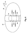
- a large area may preferably be formed separately such that a first large area 58 is formed on the driver side while a second large area 60 is formed on the passenger side as shown in Fig. 6.
- an entered portable transceiver 12 in the first large area 58 will trigger operation of only the body detection sensors 62a, 62b installed on the doors 1 and 2 on the driver side.
- an entered portable transceiver 12 in the second large area 60 will trigger operation of only the body detection sensors 62c, 62d on the doors 3 and 4 on the passenger side. That is, preparation for door unlocking operation is made only with the doors on the side where a portable transceiver 12 (i.e., the user) approaches the vehicle 10. As a result, security deterioration can be prevented.
- body detection sensors are selectively activated, battery consumption can be reduced compared to a case, such as in the second embodiment, where all body detection sensors are simultaneously activated.
- the first and second large areas 58 and 60 may be formed either simultaneously or alternately. Alternate formation can further reduce battery consumption.
- Fig. 7 is a conceptual diagram schematically showing a structure of a vehicle-side system 64 of the vehicle control system according to the third embodiment.
- a controller 68 for comprehensive control over the entire system is connected to a driver side transmitter 66a and a passenger side transmitter 66b.
- the driver side transmitter 66a sends, as a large area signal, a large area ID request signal containing a predetermined ID code to a portable transceiver 12 possibly present on the driver side of the vehicle 10.
- the driver side transmitter 66a is further connected to a driver side transmitter antenna 70a for forming a first large area 58, shown in Fig. 6, using a large area ID request signal.
- the passenger side transmitter 66b further connected to a passenger side transmitter antenna 70b, forms a second large area 60.
- the above transmitters and antenna namely the drive seat side transmitter 66a, the driver side transmitter antenna 70a, the passenger side transmitter 66b, and the passenger side transmitter antenna 70b, together constitute a large area ID request means.
- the driver side transmitter antenna 70a may be incorporated into, for example, a door handle knob on the driver side of the vehicle 10
- the passenger side transmitter antenna 70b may be incorporated into, for example, a door handle knob on the passenger side.
- the driver and passenger side transmitters 66a and 66b may be a single transmitter, differing from the above, where they are different entities.
- the controller 68 is further connected to a receiver 72 for receiving, via a receiver antenna 72a, a response ID signal containing a predetermined ID, or a response signal, sent by a portable transceiver 12 in reply to a large area ID request signal.
- the receiver antenna 72a may be installed at a desired point on a vehicle for favorable signal reception.
- the controller 68 is further connected to a memory 74, which comprises a ROM or the like.
- the memory 74 stores reference IDs to be compared for verification with response IDs, the response IDs being sent from a portable transceiver 12 in reply to a large area ID request signal sent by the driver and passenger side transmitters 66a and the 66b.
- An ID verification means included in the controller 68 verifies whether or not the received response ID coincides with a reference ID stored in the memory 74. When such verification is made, the controller 68 starts detection of a user carrying a portable transceiver 12 by activating any body detection sensors 62a-62d corresponding to either the first or second large area 58 or 60, to which the portable transceiver 12 entered.
- the controller 68 controls a door lock controller 76, mounted to the vehicle 10, to unlock the door associated with the body detection sensor having detected the user.
- the controller 68 is connected to a driven state detector 78 which determines whether or not door-lock control needs to be applied, based on driven state of the vehicle.
- the driven state detector 78 may include an activation detector for detecting activation of an engine or a speed detecting for detecting traveling of a vehicle.
- the portable transceiver 12 according to the third embodiment may have the same structure as is shown in Fig. 3 excluding the second detector 40 and the second antenna 38.
- Fig. 8 is a flowchart showing door-lock control process using the structure shown in Fig. 7.
- the controller 68 determines, based on an output from the driven state detector 78, whether or not the vehicle is in a driven state, e.g., in traveling state (S200). When such determination is positive, in other words, when a user is in the vehicle 10, the driven state of the vehicle is continually monitored and no large area ID request signals are sent as smart-entry control is unnecessary. Specifically, operation of the large area ID request means and the detection means is suspended by an operation suspension means included in the controller 68 thereby preventing battery consumption due to smart-entry control.
- a driven state e.g., in traveling state (S200).
- the controller 68 activates the driver and passenger side transmitters 66a and 66b to send a large area ID request signal (S201) for formation of the first and second large areas 58 and 60, as shown in Fig. 6.
- the controller 68 detects whether or not the receiver 72 received a response ID via the receiving antenna 72a (S202). When no response was received, that is, when no authorized portable transceiver 12 is in either the first or second large area 58 or 60, the operation flow returns to S200 to send a large area ID request signal again based on the state of the vehicle 10 (S201). On the other hand, when any response is detected at S202, the controller 68 determines whether the response was sent from a portable transceiver 12 in the first large area 58 (on the driver side ) or in the second large area 60 (on the passenger side) (S203). Here, more than one portable transceiver 12 may be used for one vehicle.
- a driver and passengers may respectively carry their transceivers 12 when approaching the vehicle.
- the controller 68 determines at S203 whether the response was detected on the driver side only, the passenger side only, or both the driver and passenger sides.
- the driver and passenger side transmitters 66a and 66b may alternately send a large area ID request signal as it will be difficult to discriminate a direction in which a portable transceiver 12 approaches if they send the signals at the same time. With alternate signal output, the approaching direction of the portable transceiver 12 can be known from the transmission timing.
- the sensors installed on the driver side namely, the body detection sensor 62a (the front sensor) and the body detection sensor 62b (the rear sensor), are solely activated (S204). Subsequently, a determination is made as to whether or not the body detection sensor s 62a or 62b is responding to the hand of a user with a portable transceiver 12 put close to the relevant door knob (S205). If the determination is affirmative, the controller 68 causes the door lock controller 76 to unlock the door associated with the responded sensor (S206). Once a door is unlocked, the body detection sensor associated with that unlocked door no longer needs to perform user detection operation.
- the body detection sensor 62d (a front sensor) and the body detection sensor 62c (a rear sensor) are driven (S210), and the controller 68 causes the door lock controller 76 to unlock only the door corresponding to the responded body detection sensor, similar to the above (S211-S213).
- the controller 68 causes the door lock controller 76 to unlock only the door corresponding to the responded body detection sensor, similar to the above (S211-S213).
- no sensor responds at S211 after a lapse of a predetermined time (S208), all currently driven body detection sensors are suspended (S209). Thereafter, the first and second large areas are again formed based on the driven state of the vehicle 10 to resume detection of a portable transceiver 12.
- a plurality of authorized portable transceivers 12 may be used for one vehicle 10 (for family or company use).
- individuals other than the driver may carry an authorized portable transceiver 12, and therefore, it is possible that, at S203, the body detection sensors on the driver side (the first large area) and on the passenger side (the second large area) may simultaneously receive a response ID which will be verified coincident with a reference ID.
- the controller 68 activates body detection sensors for all doors (S214), and, similar to the above, causes the door lock controller 76 to unlock only the door or doors corresponding to a responded body detection sensor (S215-S217).
- door-lock control is performed only on the driver side according to the residual battery amount dropped below a predetermined level. In such a case, formation of a first large area only is preferred.
- Fig. 9 shows a flowchart for transmission of a large area ID request signal at S201 in Fig. 8.
- Fig. 10 shows a timing chart indicative of operation condition of a vehicle-side system and a portable transceiver.
- a large area ID request signal having a large data amount and consuming large power for transmission, is transmitted only when response is most likely returned from a portable transceiver 12. Therefore, before transmission of a large area ID request signal, the controller 68 sends, via the driver and passenger side transmitters 66a and 66b, a signal with small power consumption, or a wake-up signal A, in a predetermined interval, such as 300 msec, to detect presence of a portable transceiver (whether or not that transceiver belongs to the concerned vehicle 10 is not detected) (S300).
- Each wake-up signal A is achieved through continuous transmission of a signal of, e.g., 134.2 KHz for 1 msec.
- a wake-up signal A is sent simultaneously to the first and second large areas 58 and 60, shown in Fig. 6.
- the controller 68 instructs the driver and passenger side transmitters 66a and 66b to transmit a wake-up signal A, and the receiver 72 to operate for a time period long enough to receive a response expected to be returned from a portable transceiver 12, if any.
- the controller 68 detects whether or not the receiver 72 received a response from a portable transceiver 12 (S301). With no response received while the receiver 72 is operating, after a predetermined period, e.g., 300 msec, measured by a timer (S302), transmission of a wave-up signal A is again instructed at S300. With this arrangement, the receiver 72 resultantly operates substantially intermittently when no response is received. As a result, power battery consumption can be reduced. On the other hand, upon receipt of a response B with respect to a wake-up signal A, as shown in Fig.
- the controller 68 When no response from a portable transceiver 12 is received in reply to the car number C (S304), in other words, when it is not assured that a portable transceiver 12 belonging to that vehicle 10 is present in the first large area 58, the controller 68 then sends a car number C toward the second large area 60 on the passenger side, as shown in Fig. 10 (S305).
- a priority code E is a code for detecting, in the case where a plurality of (e.g., eight, or 2 3 ) portable transceivers 12 are used for one vehicle (for family or company use), which one of the plurality of portable transceivers 12 is present in the second large area 50.
- the controller 68 can thereby determine that the portable transceiver which entered the second large area 60 is the one with the third priority, and send a large area ID request code G (a large area ID request signal), unique to the portable transceiver with the third priority, to the second large area 60 (S308).
- a large area ID request code G a large area ID request signal
- a large area ID request code G may be, for example, a 32 bit random code, and can also be referred to as a challenge code.
- the portable transceiver 12 generates a response code based on a challenge code according to a certain function. With this arrangement, security, which depends on a response to a challenge code, is significantly improved. Note that as many priority codes E as portable transceivers 12 used for one vehicle 10 are available. After having received a response F from a portable transceiver 12, a priority code E is no longer output, and a large area ID request code G (a large area ID request signal) will be sent instead.
- the controller 68 when a response D is received in reply to the car number C sent toward the first large area 58, the controller 68 sends a priority code E via the driver side transmitter 66a toward the first large area 58. With a response F received, the controller 68 then sends a large area ID request signal (a large area ID request code G) corresponding to the response F toward the first large area 58 (S309-S310). Thereafter, the operation flow returns to S202 (Fig. 8), where a response ID from a portable transceiver 12 is awaited.
- a large area ID request signal a large area ID request code G
- a large area ID request signal having a large data amount and consuming large power for transmission is transmitted only after the vehicle specified an approaching portable transceiver 12. Therefore, even when a plurality of portable transceivers 12 are used for a single vehicle 10, transmission of a large area ID request signal need be made only once. This can reduce battery consumption.
- car numbers are sent in the directions of the driver (D), passenger (P), and driver (D) seat sides in this order.
- the direction for sending a car number may instead be desirably determined, such as in the order of directions D, P, P, D, D, P....
- priority codes may be sent either in a predetermined order or according to a transceiver with higher priority. For example, a method in which the priority code used in previous transmission is set, through learning function of the system, to be initially transmitted in the following detection, may be preferable. Priority code transmission in this manner may increase the possibility that a large ID request signal is output more promptly, contributing to reduction of battery consumption.
- an approaching user to a vehicle can be accurately detected without applying excessive detection operation, while suppressing battery consumption, to control vehicle-mounted devices at an optimum timing
Claims (21)
- Fahrzeugsteuerungssystem mit
einer Großbereichs-Identifikations-Anforderungseinrichtung zum Senden eines Identifikations-Anforderungssignals zu einem tragbaren Sender/Empfänger, der in einem besonderen Bereich um ein Fahrzeug vorhanden ist, um einen Großbereich zu bilden,
einer Identifikations-Verifizierungseinrichtung zum Empfang einer Antwort-Identifikation in Beantwortung auf das Identifikations-Anforderungssignal, um eine Verifikation mit der empfangenen Antwort-Identifikation durchzuführen,
einer Bereichsschalteinrichtung zur Aktivierung zumindest einer Erfassungseinrichtung unter Verwendung eines Erfassungsbereichs, der kleiner als der größere Bereich ist, wenn die empfangene Antwort-Identifikation als mit einer Referenz-Identifikation übereinstimmen verifiziert worden ist, und
einer Steuerungseinrichtung zur Steuerung des Betriebs einer an einem Fahrzeug angebrachten Vorrichtung auf der Grundlage eines Erfassungsergebnisses durch die Erfassungseinrichtung. - Fahrzeugsteuerungssystem nach Anspruch 1, wobei die Steuerungseinrichtung eine Türverriegelungssteuerungseinrichtung zur Steuerung eines Verriegelungs-/Entriegelungsbetriebs in Bezug auf Türen des Fahrzeugs steuert.
- Fahrzeugsteuerungssystem nach Anspruch 1, wobei die Großbereichs-Identifikations-Anforderungseinrichtung einen ersten Großbereich und einen zweiten Großbereich jeweils in seitlichen Richtungen in Bezug auf das Fahrzeug auf der Fahrerseite und der Beifahrerseite zu einem vorbestimmten Zeitverlauf bildet, und die Bereichsschalteinrichtung individuell zumindest einen Erfassungsbereich, der entweder auf der Fahrerseite oder der Beifahrerseite des Fahrzeugs gebildet ist, auf der Grundlage einer Antwort-Identifikation, die aus einem tragbaren Sender/Empfänger gesendet worden ist, aus zumindest entweder dem ersten Großbereich oder dem zweiten Großbereich aktiviert.
- Fahrzeugsteuerungssystem nach Anspruch 1, wobei die Erfassungseinrichtung eine Kleinbereichs-Identifikations-Anforderungseinrichtung zum Senden eines Identifikations-Anforderungssignal ist, das sich von dem zu dem Großbereich zu sendenden Identifikations-Anforderungssignal unterscheidet, und die Steuerungseinrichtung den Betrieb der an dem Fahrzeug angebrachten Vorrichtung steuert, wenn die Identifikations-Verifikationsvorrichtung verifiziert, dass eine Antwort-Identifikation in Beantwortung auf das aus der Kleinbereichs-Identifikations-Anforderungseinrichtung gesendeten Identifikations-Anforderungssignal mit einer Referenz-Identifikation übereinstimmt.
- Fahrzeugsteuerungssystem nach Anspruch 1, wobei die Erfassungseinrichtung ein Körpererfassungssensor zur Erfassung einer herankommenden Fahrzeuganwenders ist.
- Fahrzeugsteuerungssystem nach Anspruch 1, weiterhin mit einer Betriebsbereichsauswahleinrichtung zur wahlweisen Aktivierung einer Erfassungseinrichtung, die einer besonderen Stelle zugeordnet ist.
- Fahrzeugsteuerungssystem nach Anspruch 4, weiterhin mit einer Bereichsänderungseinrichtung zur Änderung eines Sendebereichs für das aus der Kleinbereichs-Identifikations-Anforderungseinrichtung gesendete Signal.
- Fahrzeugsteuerungssystem nach Anspruch 2, wobei die Bereichsschalteinrichtung den Betrieb der Erfassungseinrichtung aussetzt, die einer entriegelten Tür zugeordnet ist.
- Fahrzeugsteuerungssystem nach Anspruch 1, weiterhin mit
einer Antriebszustandserfassungseinrichtung zur Erfassung eines Antriebszustands des Fahrzeugs, und
einer Betriebaussetzungseinrichtung zur Aussetzung des Betriebs der Großbereichs-Identifikations-Anforderungseinrichtung und der Erfassungseinrichtung, während der Antriebszustand des Fahrzeugs weiter erfasst wird. - Fahrzeugsteuerungssystem nach Anspruch 3, wobei die Großbereichs-Identifikations-Anforderungseinrichtung ein Aufwecksignal zu einem vorbestimmten Intervall sendet, um zu erfassen, ob in der Umgebung des Fahrzeugs ein tragbarer Sender/Empfänger vorhanden ist oder nicht, und den ersten Großbereich und den zweiten Großbereich auf der Grundlage einer vorbestimmten Prioritätsreihenfolge bildet, wenn das Vorhandensein des tragbaren Sender/Empfängers bestätigt wird.
- Fahrzeugsteuerungssystem nach Anspruch 2, wobei die Großbereichs-Identifikations-Anforderungseinrichtung einen ersten Großbereich und einen zweiten Großbereich in seitlichen Richtung in Bezug auf das Fahrzeug jeweils auf der Fahrerseite und der Beifahrerseite zu einem vorbestimmten Zeitverlauf bildet, und die Bereichsschalteinrichtung individuell zumindest einen Erfassungsbereich, der entweder auf der Fahrerseite oder der Beifahrerseite gebildet ist, auf der Grundlage einer Antwort-Identifikation aktiviert, die aus einem tragbaren Sender/Empfänger gesendet wird, der in zumindest entweder dem ersten Großbereich oder den zweiten Großbereich gelangt ist.
- Fahrzeugsteuerungssystem nach Anspruch 11, wobei die Erfassungseinrichtung eine Kleinbereichs-Identifikations-Anforderungseinrichtung zum Senden eines Identifikations-Anforderungssignal ist, das sich von dem zu dem besonderen Bereich innerhalb des Großbereichs zu sendenden Identifikations-Anforderungssignal unterscheidet, und die Steuerungseinrichtung den Betrieb der an dem Fahrzeug angebrachten Vorrichtung steuert, wenn die Identifikations-Verifikationsvorrichtung verifiziert, dass eine Antwort-Identifikation in Beantwortung auf das aus der Kleinbereichs-Identifikations-Anforderungseinrichtung gesendeten Identifikations-Anforderungssignal mit einer Referenz-Identifikation übereinstimmt.
- Fahrzeugsteuerungssystem nach Anspruch 11, wobei die Erfassungseinrichtung ein Körpererfassungssensor zur Erfassung einer herankommenden Fahrzeuganwenders ist.
- Fahrzeugsteuerungssystem nach Anspruch 11, weiterhin mit einer Betriebsbereichsauswahleinrichtung zur wahlweisen Aktivierung einer Erfassungseinrichtung, die einer besonderen Stelle zugeordnet ist.
- Fahrzeugsteuerungssystem nach Anspruch 11, wobei die Bereichsschalteinrichtung den Betrieb der Erfassungseinrichtung aussetzt, die einer entriegelten Tür zugeordnet ist.
- Fahrzeugsteuerungssystem nach Anspruch 11, weiterhin mit
einer Antriebszustandserfassungseinrichtung zur Erfassung eines Antriebszustands des Fahrzeugs, und
einer Betriebaussetzungseinrichtung zur Aussetzung des Betriebs der Großbereichs-Identifikations-Anforderungseinrichtung und der Erfassungseinrichtung, während der Antriebszustand des Fahrzeugs weiter erfasst wird. - Fahrzeugsteuerungssystem nach Anspruch 11, wobei die Großbereichs-Identifikations-Anforderungseinrichtung ein Aufwecksignal zu einem vorbestimmten Intervall sendet, um zu erfassen, ob in der Umgebung des Fahrzeugs ein tragbarer Sender/Empfänger vorhanden ist oder nicht, und den ersten Großbereich und den zweiten Großbereich auf der Grundlage einer vorbestimmten Prioritätsreihenfolge bildet, wenn das Vorhandensein des tragbaren Sender/Empfängers bestätigt wird.
- Fahrzeugsteuerungssystem nach Anspruch 12, weiterhin mit einer Betriebsbereichsauswahleinrichtung zur wahlweisen Aktivierung einer Erfassungseinrichtung, die einer besonderen Stelle zugeordnet ist.
- Fahrzeugsteuerungssystem nach Anspruch 12, weiterhin mit einer Bereichsänderungseinrichtung zur Änderung eines Sendebereichs für das aus der Kleinbereichs-Identifikations-Anforderungseinrichtung gesendete Signal.
- Fahrzeugsteuerungssystem nach Anspruch 12, wobei die Bereichsschalteinrichtung den Betrieb der Erfassungseinrichtung aussetzt, die einer entriegelten Tür zugeordnet ist.
- Fahrzeugsteuerungssystem nach Anspruch 12, weiterhin mit
einer Antriebszustandserfassungseinrichtung zur Erfassung eines Antriebszustands des Fahrzeugs, und
einer Betriebaussetzungseinrichtung zur Aussetzung des Betriebs der Großbereichs-Identifikations-Anforderungseinrichtung und der Erfassungseinrichtung, während der Antriebszustand des Fahrzeugs weiter erfasst wird.
Applications Claiming Priority (4)
| Application Number | Priority Date | Filing Date | Title |
|---|---|---|---|
| JP17122798 | 1998-06-18 | ||
| JP17122798 | 1998-06-18 | ||
| JP36144098 | 1998-12-18 | ||
| JP36144098A JP3533966B2 (ja) | 1998-06-18 | 1998-12-18 | 車両制御システム |
Publications (3)
| Publication Number | Publication Date |
|---|---|
| EP0965710A2 EP0965710A2 (de) | 1999-12-22 |
| EP0965710A3 EP0965710A3 (de) | 2000-08-09 |
| EP0965710B1 true EP0965710B1 (de) | 2003-12-17 |
Family
ID=26494029
Family Applications (1)
| Application Number | Title | Priority Date | Filing Date |
|---|---|---|---|
| EP19990304272 Expired - Lifetime EP0965710B1 (de) | 1998-06-18 | 1999-06-02 | Fahrzeugsteuerungssystem |
Country Status (4)
| Country | Link |
|---|---|
| US (1) | US6552649B1 (de) |
| EP (1) | EP0965710B1 (de) |
| JP (1) | JP3533966B2 (de) |
| DE (1) | DE69913607T2 (de) |
Cited By (1)
| Publication number | Priority date | Publication date | Assignee | Title |
|---|---|---|---|---|
| CN114312668A (zh) * | 2017-09-27 | 2022-04-12 | 丰田自动车株式会社 | 车辆控制系统 |
Families Citing this family (146)
| Publication number | Priority date | Publication date | Assignee | Title |
|---|---|---|---|---|
| US20070126561A1 (en) * | 2000-09-08 | 2007-06-07 | Automotive Technologies International, Inc. | Integrated Keyless Entry System and Vehicle Component Monitoring |
| US20130275008A1 (en) * | 1997-03-17 | 2013-10-17 | American Vehicular Sciences Llc | Vehicular Door Control Systems |
| JP3809934B2 (ja) * | 1999-08-09 | 2006-08-16 | 本田技研工業株式会社 | 車両の遠隔制御システム |
| FR2804545B1 (fr) * | 2000-01-31 | 2002-03-22 | Valeo Securite Habitacle | Vehicule automobile equipe d'un systeme d'acces dit "mains libres" avec des antennes placees dans des poignees de retenue de passager |
| JP4350864B2 (ja) * | 2000-03-01 | 2009-10-21 | アルプス電気株式会社 | キーレスエントリー装置 |
| JP2001254549A (ja) * | 2000-03-10 | 2001-09-21 | Omron Corp | 制御装置 |
| DE10015646A1 (de) * | 2000-03-29 | 2001-10-11 | Bosch Gmbh Robert | Vorrichtung zur Benutzerwarnung in einem Kraftfahrzeug |
| US20010054952A1 (en) * | 2000-06-21 | 2001-12-27 | Desai Tejas B. | Automatic port operation |
| DE60107512T2 (de) * | 2000-09-19 | 2005-12-15 | Land Rover, Lighthorne | Sicherheitssystem |
| AUPR030500A0 (en) * | 2000-09-22 | 2000-10-12 | Australian Arrow Pty Ltd | Proximity activated entry system |
| JP3559764B2 (ja) * | 2000-11-30 | 2004-09-02 | 株式会社鷹山 | 建物、ドア、ドアノブ、手すりおよび伝送方法 |
| DE10063252A1 (de) * | 2000-12-19 | 2002-07-04 | Delphi Tech Inc | Funk-Fernbedienungssystem insbesondere für Kraftfahrzeuge |
| DE10104856A1 (de) * | 2001-02-03 | 2002-08-29 | Conti Temic Microelectronic | Verfahren zur Inbetriebnahme eines motorangetriebenen Kraftfahrzeugs |
| FR2826732B1 (fr) * | 2001-06-27 | 2003-09-26 | Siemens Automotive Sa | Procede de localisation d'un badge pour un systeme main libre d'un vehicule automobile |
| US6882268B2 (en) * | 2001-07-05 | 2005-04-19 | Em Microelectronic-Marin Sa | Method for keyless unlocking of an access door to a closed space |
| JP3646077B2 (ja) * | 2001-07-05 | 2005-05-11 | 株式会社ホンダロック | 車載機器遠隔制御装置 |
| EP1283503A3 (de) * | 2001-08-10 | 2004-05-26 | ArvinMeritor Light Vehicle Systems (UK) Ltd | Zugangskontrollsystem und -verfahren |
| JP4214199B2 (ja) * | 2001-11-19 | 2009-01-28 | 株式会社デンソー | 車両のドアアンロック装置 |
| US7283034B2 (en) * | 2001-12-10 | 2007-10-16 | Omron Corporation | Object sensor and controller |
| FR2837014B1 (fr) * | 2002-03-08 | 2004-07-09 | Valeo Electronique | Procede de scrutation de badges identifiant pour vehicule automobile |
| US20030216817A1 (en) * | 2002-05-16 | 2003-11-20 | Richard Pudney | Vehicle access system with sensor |
| JP4047663B2 (ja) * | 2002-08-29 | 2008-02-13 | 株式会社東海理化電機製作所 | 車両用施解錠制御装置 |
| JP3983634B2 (ja) * | 2002-09-02 | 2007-09-26 | カルソニックカンセイ株式会社 | 車両用無線装置 |
| FR2845188A1 (fr) * | 2002-09-30 | 2004-04-02 | Valeo Electronique | Procede et organe de commande d'un systeme d'acces mains-libres pour vehicule automobile |
| JP3988618B2 (ja) * | 2002-10-30 | 2007-10-10 | 株式会社デンソー | 車両の遠隔制御装置 |
| AU2002952753A0 (en) * | 2002-11-19 | 2003-01-16 | Australian Arrow Pty Ltd | Passive entry system |
| JP2004176470A (ja) * | 2002-11-28 | 2004-06-24 | Aisin Seiki Co Ltd | 車両用ドア作動システム |
| US7205884B2 (en) * | 2002-12-19 | 2007-04-17 | Denso Corporation | Vehicle electronic key system |
| JP4196172B2 (ja) * | 2003-01-10 | 2008-12-17 | オムロン株式会社 | 検知装置及び錠制御装置 |
| JP4096178B2 (ja) * | 2003-01-20 | 2008-06-04 | オムロン株式会社 | 検知装置及び錠制御装置 |
| JP4451096B2 (ja) * | 2003-08-06 | 2010-04-14 | アルパイン株式会社 | キーレスエントリー装置及びシステム |
| JP4349040B2 (ja) | 2003-08-21 | 2009-10-21 | 三菱自動車工業株式会社 | 車両のドア解錠制御装置 |
| JP4483236B2 (ja) * | 2003-09-01 | 2010-06-16 | オムロン株式会社 | 無線端末位置検出装置及び無線端末位置検出方法 |
| JP2005109614A (ja) * | 2003-09-29 | 2005-04-21 | Sanyo Electric Co Ltd | 受信装置 |
| DE102005013008B4 (de) * | 2004-03-19 | 2011-06-01 | Ident Technology Ag | Fahrzeugtürverriegelungssystem |
| TWM254389U (en) * | 2004-03-31 | 2005-01-01 | Tung Thih Entpr Co Ltd | Anti-theft device with blue-tooth recognition for car |
| JP4321349B2 (ja) * | 2004-05-12 | 2009-08-26 | 株式会社デンソー | スマートエントリシステム |
| GB0415219D0 (en) * | 2004-07-07 | 2004-08-11 | Koninkl Philips Electronics Nv | Improvements in or relating to time-of-flight ranging systems |
| US20060066439A1 (en) * | 2004-09-24 | 2006-03-30 | Thomas Keeling | Smart key entry system |
| US7310043B2 (en) | 2004-10-08 | 2007-12-18 | Wayne-Dalton Corp. | System for automatically moving access barriers and methods for adjusting system sensitivity |
| US7292134B2 (en) * | 2004-11-01 | 2007-11-06 | Lear Corporation | Selectable range remote entry system |
| US7403743B2 (en) * | 2004-12-31 | 2008-07-22 | Sony Ericsson Mobile Communications Ab | System and method to unlock hidden multimedia content |
| DE102006015332A1 (de) * | 2005-04-04 | 2006-11-16 | Denso Corp., Kariya | Gastservice-System für Fahrzeugnutzer |
| JP4667984B2 (ja) * | 2005-07-05 | 2011-04-13 | 株式会社日本自動車部品総合研究所 | 車両の開閉自在な部材を開放するための制御装置 |
| MY151605A (en) * | 2005-07-28 | 2014-06-30 | Inventio Ag | Method of controlling access to an area |
| EP1755085B1 (de) * | 2005-07-28 | 2018-03-21 | Inventio AG | Verfahren zur Kontrolle des Zugangs für eine Tür einer Aufzugsanlage |
| DE102005042402A1 (de) * | 2005-09-06 | 2007-03-08 | Bayerische Motoren Werke Ag | Kraftfahrzeug mit automatisch öffnender Klappe |
| US7683757B2 (en) * | 2005-10-18 | 2010-03-23 | Lear Corporation | Multi-antenna system and method for remotely controlling a function |
| US20070109093A1 (en) * | 2005-11-11 | 2007-05-17 | Fujitsu Ten Limited | Vehicle control system and vehicle control apparatus |
| JP4561612B2 (ja) * | 2005-11-25 | 2010-10-13 | 株式会社デンソー | 車両ドア制御システム |
| JP4604984B2 (ja) * | 2005-11-25 | 2011-01-05 | 株式会社デンソー | 車載機器制御システム |
| DE102006001719A1 (de) * | 2006-01-13 | 2007-08-02 | Ford Global Technologies, LLC, Dearborn | Vorrichtung zur Ansteuerung einer Fahrzeugtürverriegelung |
| US8427276B2 (en) * | 2006-02-24 | 2013-04-23 | Denso International America, Inc. | Apparatus for automatically initiating sequence of vehicle functions |
| US9024721B2 (en) | 2006-02-27 | 2015-05-05 | Denso International America, Inc. | Apparatus for automatically changing state of vehicle closure |
| US20070200670A1 (en) * | 2006-02-27 | 2007-08-30 | Denso International America, Inc. | Apparatus for automatically changing state of vehicle closure |
| US20080001706A1 (en) * | 2006-06-19 | 2008-01-03 | Kaba Iico Inc. | Low power detection method for proximity lock |
| JP4614138B2 (ja) * | 2006-09-12 | 2011-01-19 | 株式会社デンソー | 車載用無線送信装置及び車載用無線送信システム |
| EP2062358A1 (de) * | 2006-09-13 | 2009-05-27 | Siemens Aktiengesellschaft | Verfahren zur schaltbereichskontrolle eines berührungslosen schaltsystems |
| AU2007333025B2 (en) * | 2006-12-13 | 2012-03-08 | Crown Equipment Corporation | Fleet management system |
| US11225404B2 (en) | 2006-12-13 | 2022-01-18 | Crown Equipment Corporation | Information system for industrial vehicles |
| US10600256B2 (en) | 2006-12-13 | 2020-03-24 | Crown Equipment Corporation | Impact sensing usable with fleet management system |
| DE102007010888B4 (de) * | 2007-03-06 | 2010-03-04 | Continental Automotive Gmbh | Steuergerät zur drahtlosen Kommunikation mit einer peripheren Einheit |
| JP5235355B2 (ja) * | 2007-08-22 | 2013-07-10 | オムロンオートモーティブエレクトロニクス株式会社 | 通信システム、送信機および方法、並びに受信機および方法 |
| JP2009062688A (ja) * | 2007-09-04 | 2009-03-26 | Tokai Rika Co Ltd | 車両用通信システム |
| EP2062789A1 (de) * | 2007-11-21 | 2009-05-27 | Delphi Technologies, Inc. | Insassenerfassungssystem |
| DE102007060609A1 (de) * | 2007-12-13 | 2009-06-18 | Huf Hülsbeck & Fürst Gmbh & Co. Kg | Verfahren zur Anzeige einer Information |
| DE102008008089B4 (de) * | 2008-02-08 | 2010-05-06 | Continental Automotive Gmbh | Anordnung und Verfahren zur Detektion eines Transponders |
| EP2098671B1 (de) * | 2008-03-04 | 2013-07-31 | Hella KGaA Hueck & Co. | Kraftfahrzeug mit einem automatisch in eine Offen- und eine Schließstellung verstellbaren Fahrzeugteil |
| EP2098672A1 (de) * | 2008-03-04 | 2009-09-09 | Hella KG Hueck & Co. | Kraftfahrzeug mit einem automatisch in eine Offen- und eine Schließstellung verstellbaren Fahrzeugteil |
| US20090256677A1 (en) * | 2008-04-10 | 2009-10-15 | Lear Corporation | Passive entry system and method |
| US8098130B2 (en) * | 2008-06-11 | 2012-01-17 | Flextronics Automotive Inc. | System and method for activating electromechanical systems using flexible intelligent radio frequency modules |
| JP5243868B2 (ja) * | 2008-07-09 | 2013-07-24 | インターナショナル・ビジネス・マシーンズ・コーポレーション | Icタグが保持する情報を認識する装置及び方法 |
| DE102009042862B4 (de) * | 2008-09-25 | 2021-01-28 | Denso Corporation | Intelligentes Zutrittssystem |
| FR2936545B1 (fr) * | 2008-10-01 | 2017-03-10 | Valeo Securite Habitacle | Dispositif de deverrouillage automatique d'un ouvrant de vehicule automatique. |
| FR2936546B1 (fr) * | 2008-10-01 | 2017-03-10 | Valeo Securite Habitacle | Dispositif de deverrouillage automatique d'un ouvrant de vehicule automatique. |
| US8427278B2 (en) * | 2008-10-17 | 2013-04-23 | Robert Bosch Gmbh | Automation and security system |
| JP2010216176A (ja) * | 2009-03-18 | 2010-09-30 | Aisin Seiki Co Ltd | 車両用ドアハンドル装置 |
| US8203424B2 (en) * | 2009-03-25 | 2012-06-19 | Lear Corporation | Automatic walk-away detection |
| US8334758B2 (en) * | 2009-04-13 | 2012-12-18 | Flextronics Automotive, Inc. | LIN BUS remote control system |
| JP5299688B2 (ja) * | 2009-06-03 | 2013-09-25 | アイシン精機株式会社 | 車両周辺監視方法及び車両周辺監視装置 |
| DE102010010057B4 (de) * | 2010-03-03 | 2012-09-06 | Continental Automotive Gmbh | Verfahren zum Steuern einer Tür eines Fahrzeugs |
| JP5370338B2 (ja) * | 2010-11-01 | 2013-12-18 | 株式会社デンソー | キーレスエントリシステムおよび携帯機 |
| KR101703238B1 (ko) * | 2011-05-19 | 2017-02-06 | 콘티넨탈 오토모티브 시스템 주식회사 | 차량등 구동 제어 시스템 및 그 방법 |
| JP5556784B2 (ja) | 2011-10-06 | 2014-07-23 | 株式会社デンソー | 車両制御システムおよび携帯機 |
| US8801245B2 (en) | 2011-11-14 | 2014-08-12 | Magna Mirrors Of America, Inc. | Illumination module for vehicle |
| CN102400605B (zh) * | 2011-11-16 | 2017-11-10 | 深圳市警豹电子科技有限公司 | 分频分功率分码发送的感应式汽车进入方法 |
| JP5929586B2 (ja) | 2012-07-24 | 2016-06-08 | 株式会社デンソー | 車載機器制御システム |
| GB201219261D0 (en) | 2012-10-26 | 2012-12-12 | Jaguar Cars | Vehicle access system and method |
| JP6038601B2 (ja) * | 2012-11-09 | 2016-12-07 | Kddi株式会社 | ウェイクアップ機能を備えた解施錠制御用無線端末、システム、方法及びプログラム |
| DE102012025366A1 (de) * | 2012-12-28 | 2014-07-03 | Volkswagen Aktiengesellschaft | Schließvorrichtung für ein Fahrzeug und Verfahren zum Betreiben einer Schließvorrichtung |
| US9852560B2 (en) | 2013-03-08 | 2017-12-26 | Lear Corporation | Vehicle remote function system and method for effectuating vehicle operations based on vehicle FOB movement |
| US9679430B2 (en) | 2013-03-08 | 2017-06-13 | Lear Corporation | Vehicle remote function system and method for determining vehicle FOB locations using adaptive filtering |
| FR3007876B1 (fr) * | 2013-06-28 | 2016-09-16 | Continental Automotive France | Procede de traitement de signal de presence dans un systeme d'acces main libre d'un vehicule a capteurs capacitifs |
| JP6111169B2 (ja) * | 2013-08-26 | 2017-04-05 | 本田技研工業株式会社 | スマートエントリシステム |
| JP6187166B2 (ja) | 2013-11-04 | 2017-08-30 | 株式会社デンソー | 車両システム、車載装置、及び携帯機 |
| DE102014105241A1 (de) * | 2013-12-05 | 2015-06-11 | Deutsche Post Ag | Verriegelungseinheit, Gehäuse mit Verriegelungseinheit und Verfahren zum Entriegeln von ein oder mehreren Türen des Gehäuses |
| DE102014010343A1 (de) * | 2014-07-11 | 2016-01-14 | Audi Ag | Verfahren zum berührungslosen Betätigen einer Schließvorrichtung eines Fahrzeugs, Schließvorrichtung und Funkschlüssel |
| US9747736B2 (en) * | 2014-08-05 | 2017-08-29 | Texas Instruments Deutschland Gmbh | Multiple-band identification and ranging |
| DE102014218571B4 (de) * | 2014-09-16 | 2019-05-09 | Volkswagen Aktiengesellschaft | Elektronische Schlüsselvorrichtung für ein elektronisches Zugangssystem |
| DE102014119401B4 (de) * | 2014-12-22 | 2022-11-10 | Bayerische Motoren Werke Aktiengesellschaft | Verfahren zur Nutzung der relativen Position eines Nutzers zu einem Fahrzeug und Nutzungssystem |
| JP6357427B2 (ja) | 2015-01-16 | 2018-07-11 | 株式会社デンソー | 車両用制御システム |
| JP6428395B2 (ja) * | 2015-03-11 | 2018-11-28 | 株式会社デンソー | 近距離無線通信システム及び近距離無線通信装置 |
| JP2016171486A (ja) * | 2015-03-13 | 2016-09-23 | オムロンオートモーティブエレクトロニクス株式会社 | 車両無線通信システム、車両制御装置、携帯機 |
| JP6565267B2 (ja) * | 2015-03-30 | 2019-08-28 | 株式会社デンソー | 車両制御システム、車両制御装置 |
| DE102015105001A1 (de) | 2015-03-31 | 2016-10-06 | Atmel Corporation | Vorrichtung zum Schließen und/oder Öffnen |
| RU2702243C2 (ru) * | 2015-05-15 | 2019-10-07 | ФОРД ГЛОУБАЛ ТЕКНОЛОДЖИЗ, ЭлЭлСи | Определение расположения пользователя транспортного средства |
| DE102015108026C5 (de) * | 2015-05-21 | 2020-03-05 | Carl Fuhr Gmbh & Co. Kg | Schließanlage und Verfahren zum Betrieb einer Schließanlage für eine Gebäudetür |
| DE102015108027A1 (de) * | 2015-05-21 | 2016-11-24 | Carl Fuhr Gmbh & Co. Kg | Schließanlage für eine Gebäudetür |
| US10118594B2 (en) | 2015-08-21 | 2018-11-06 | Honda Motor Co., Ltd. | System and method for reducing power consumption for a smart entry door handle in a vehicle |
| CN105346508A (zh) * | 2015-11-05 | 2016-02-24 | 重庆熠美实业发展有限公司 | 基于无钥匙进入系统的解锁方法 |
| JP6429169B2 (ja) | 2015-12-10 | 2018-11-28 | パナソニックIpマネジメント株式会社 | 車載器、携帯機、及び車両用無線通信システム |
| JP2017128884A (ja) * | 2016-01-19 | 2017-07-27 | 株式会社東海理化電機製作所 | 車両用ドアロック装置 |
| DE102016203521A1 (de) | 2016-03-03 | 2017-09-07 | Volkswagen Aktiengesellschaft | Verfahren und System für ein Authentifizieren eines Benutzers sowie ein Kraftfahrzeug |
| US10043326B2 (en) * | 2016-03-24 | 2018-08-07 | Ford Global Technologies, Llc | Driver indentification using vehicle approach vectors |
| CN109074618B (zh) | 2016-04-11 | 2024-04-09 | 开利公司 | 在与多个访问控件交互时捕获用户意图 |
| CN109074691B (zh) * | 2016-04-11 | 2022-07-29 | 开利公司 | 在与多个访问控制装置交互时捕获个人用户意图 |
| WO2017180388A1 (en) | 2016-04-11 | 2017-10-19 | Carrier Corporation | Capturing behavioral user intent when interacting with multiple access controls |
| CN109074690A (zh) | 2016-04-11 | 2018-12-21 | 开利公司 | 在与多个访问控制装置交互时捕获通信用户意图 |
| US10647289B2 (en) | 2016-11-15 | 2020-05-12 | Ford Global Technologies, Llc | Vehicle driver locator |
| DE102016223252B4 (de) | 2016-11-24 | 2020-03-26 | Continental Automotive Gmbh | Zugangsvorrichtung für ein Fahrzeug |
| US10380817B2 (en) | 2016-11-28 | 2019-08-13 | Honda Motor Co., Ltd. | System and method for providing hands free operation of at least one vehicle door |
| US10815717B2 (en) | 2016-11-28 | 2020-10-27 | Honda Motor Co., Ltd. | System and method for providing hands free operation of at least one vehicle door |
| JP2018101871A (ja) * | 2016-12-20 | 2018-06-28 | 株式会社デンソー | 携帯機検出装置、携帯機検出方法 |
| DE102017203504A1 (de) | 2017-03-03 | 2018-09-06 | Volkswagen Aktiengesellschaft | Verfahren zur Entriegelung eines Ladesteckers in Zusammenhang mit einem Ladevorgang eines elektrisch antreibbaren Fahrzeugs |
| CN107248207A (zh) * | 2017-04-17 | 2017-10-13 | 朗曦科技(上海)有限公司 | 基于移动终端身份验证和位置感知的智能控制方法和系统 |
| EP3396640A1 (de) * | 2017-04-28 | 2018-10-31 | HUF Hülsbeck & Fürst GmbH & Co. KG | Tragbarer id-geber für ein authentifizierungssystem und verfahren zum betreiben eines authentifizierungssystems |
| DE102017120524A1 (de) | 2017-04-28 | 2018-10-31 | Huf Hülsbeck & Fürst Gmbh & Co. Kg | Tragbarer ID-Geber für ein Authentifizierungssystem und Verfahren zum Betreiben eines Authentifizierungssystems |
| DE102017109293A1 (de) * | 2017-04-28 | 2018-10-31 | Huf Hülsbeck & Fürst Gmbh & Co. Kg | Verfahren zum Betreiben eines Authentifizierungssystems und Authentifizierungssystem |
| JP6606128B2 (ja) * | 2017-06-20 | 2019-11-13 | 矢崎総業株式会社 | 車両用照明装置 |
| KR102406511B1 (ko) * | 2017-07-04 | 2022-06-10 | 현대자동차주식회사 | 차량 시스템 및 그 제어 방법 |
| US10716068B2 (en) * | 2017-10-13 | 2020-07-14 | Denso International America, Inc. | Power saving methods for communication in localization systems |
| US10640087B2 (en) | 2018-02-20 | 2020-05-05 | Ford Global Technologies, Llc | Dead zone mitigation for a passive entry system of a vehicle |
| US11180158B1 (en) * | 2018-07-31 | 2021-11-23 | United Services Automobile Association (Usaa) | Routing or driving systems and methods based on sleep pattern information |
| EP3627456A1 (de) * | 2018-09-24 | 2020-03-25 | Hoppe Ag | Betätigungshandhabe mit zutrittskontrollsystem |
| JP6760351B2 (ja) * | 2018-10-30 | 2020-09-23 | 株式会社デンソー | 車載近距離無線通信装置、親機、及び子機 |
| DE102019114917A1 (de) * | 2019-06-04 | 2020-12-10 | U-Shin Deutschland Zugangssysteme Gmbh | Verfahren zur Zugangssteuerung für ein Kraftfahrzeug und Zugangssteuerungssystem |
| DE102019135665B4 (de) | 2019-12-23 | 2023-02-16 | U-Shin Deutschland Zugangssysteme Gmbh | Verfahren zur Kalibrierung einer Positionserfassung eines tragbaren Schüsselelements und Zugangssteuerungssystem |
| JP7366802B2 (ja) * | 2020-02-27 | 2023-10-23 | 株式会社東海理化電機製作所 | 通信装置及び制御方法 |
| JP7177804B2 (ja) * | 2020-07-27 | 2022-11-24 | 本田技研工業株式会社 | 車両制御システム、及び車両制御方法 |
| JP7107994B2 (ja) * | 2020-07-27 | 2022-07-27 | 本田技研工業株式会社 | 車両制御システム、及び車両制御方法 |
| DE102020129844A1 (de) | 2020-11-12 | 2022-05-12 | Kiekert Aktiengesellschaft | Verfahren und Vorrichtung zur Ansteuerung wenigstens eines Kraftfahrzeug-Verschlusselementes |
| US11766912B2 (en) | 2020-12-14 | 2023-09-26 | Dana Heavy Vehicle Systems Group, Llc | Kneeling position for electric medium-duty vehicle |
| JP7181331B2 (ja) * | 2021-03-24 | 2022-11-30 | 本田技研工業株式会社 | 車両制御装置、車両制御方法、及びプログラム |
| US11608030B2 (en) * | 2021-08-12 | 2023-03-21 | Toyota Connected North America, Inc. | Vehicle surveillance system and early vehicle warning of potential threat |
| US11894136B2 (en) | 2021-08-12 | 2024-02-06 | Toyota Motor North America, Inc. | Occupant injury determination |
| US11887460B2 (en) | 2021-08-12 | 2024-01-30 | Toyota Motor North America, Inc. | Transport-related contact notification |
Family Cites Families (9)
| Publication number | Priority date | Publication date | Assignee | Title |
|---|---|---|---|---|
| JPS6237479A (ja) * | 1985-08-12 | 1987-02-18 | 日産自動車株式会社 | 無線式施解錠制御装置 |
| EP0502567B1 (de) * | 1991-03-06 | 1995-05-03 | Delco Electronics Corporation | Fernbetätigungssystem zum Regeln einer Funktion einer Basisstation |
| JPH05106376A (ja) | 1991-10-17 | 1993-04-27 | Nissan Motor Co Ltd | キーレスエントリーシステム |
| JP3192715B2 (ja) | 1991-12-04 | 2001-07-30 | 富士通テン株式会社 | 車両用ワイヤレスドアロック制御装置 |
| FR2706934B1 (de) * | 1993-06-21 | 1995-10-13 | Valeo Electronique | |
| FR2707030B1 (de) * | 1993-06-21 | 1995-07-28 | Valeo Electronique | |
| JPH07150835A (ja) | 1993-11-29 | 1995-06-13 | Alpha Corp | 運転管理システム |
| US5532709A (en) * | 1994-11-02 | 1996-07-02 | Ford Motor Company | Directional antenna for vehicle entry system |
| US5973611A (en) * | 1995-03-27 | 1999-10-26 | Ut Automotive Dearborn, Inc. | Hands-free remote entry system |
-
1998
- 1998-12-18 JP JP36144098A patent/JP3533966B2/ja not_active Expired - Lifetime
-
1999
- 1999-06-02 DE DE1999613607 patent/DE69913607T2/de not_active Expired - Lifetime
- 1999-06-02 EP EP19990304272 patent/EP0965710B1/de not_active Expired - Lifetime
- 1999-06-09 US US09/328,340 patent/US6552649B1/en not_active Expired - Lifetime
Cited By (1)
| Publication number | Priority date | Publication date | Assignee | Title |
|---|---|---|---|---|
| CN114312668A (zh) * | 2017-09-27 | 2022-04-12 | 丰田自动车株式会社 | 车辆控制系统 |
Also Published As
| Publication number | Publication date |
|---|---|
| DE69913607D1 (de) | 2004-01-29 |
| US6552649B1 (en) | 2003-04-22 |
| JP2000073635A (ja) | 2000-03-07 |
| EP0965710A2 (de) | 1999-12-22 |
| EP0965710A3 (de) | 2000-08-09 |
| DE69913607T2 (de) | 2004-09-30 |
| JP3533966B2 (ja) | 2004-06-07 |
Similar Documents
| Publication | Publication Date | Title |
|---|---|---|
| EP0965710B1 (de) | Fahrzeugsteuerungssystem | |
| EP0735219B1 (de) | Handfreies ferngesteuertes Eingangssystem | |
| US7305284B2 (en) | Remote control system and method for vehicle | |
| US7336151B2 (en) | Radio type locking/unlocking device | |
| KR100766189B1 (ko) | 차량 도어 제어 시스템 및 방법 | |
| JP2906042B2 (ja) | 乗り逃げ防止及び遠隔操作可能な機能の始動用キー・車両間通信装置 | |
| US6998958B2 (en) | Remote control system for a vehicle | |
| JP4552169B2 (ja) | 車両の開閉体制御装置 | |
| US7915998B2 (en) | Vehicle control system and vehicle control apparatus | |
| US7394350B2 (en) | Power-saving on-vehicle controller | |
| US7181189B2 (en) | Vehicular remote control system and tire pressure monitoring system | |
| EP0426114B1 (de) | Schlüsselloses Schlosssystem für ein Kraftfahrzeug | |
| JP4214199B2 (ja) | 車両のドアアンロック装置 | |
| US6801120B2 (en) | Control apparatus | |
| US7683764B2 (en) | Automatic locking failsafe for vehicles with passive keys | |
| JP3976186B2 (ja) | 無線式施解錠装置 | |
| US20010028297A1 (en) | Control apparatus and control method | |
| JP2008069630A (ja) | 車両用のアクセス回路 | |
| JPH112053A (ja) | 車両用パッシブエントリ制御システム | |
| JP2001295524A (ja) | 制御装置 | |
| JP3659583B2 (ja) | 車載機器遠隔制御システム | |
| CN107945316B (zh) | 门控制系统、控制装置和移动装置 | |
| EP1283503A2 (de) | Zugangskontrollsystem und -verfahren | |
| JP3520786B2 (ja) | 車載機器遠隔制御装置 | |
| JP2000103316A (ja) | 車載機器遠隔制御装置 |
Legal Events
| Date | Code | Title | Description |
|---|---|---|---|
| PUAI | Public reference made under article 153(3) epc to a published international application that has entered the european phase |
Free format text: ORIGINAL CODE: 0009012 |
|
| 17P | Request for examination filed |
Effective date: 19990610 |
|
| AK | Designated contracting states |
Kind code of ref document: A2 Designated state(s): DE FR GB |
|
| AX | Request for extension of the european patent |
Free format text: AL;LT;LV;MK;RO;SI |
|
| PUAL | Search report despatched |
Free format text: ORIGINAL CODE: 0009013 |
|
| AK | Designated contracting states |
Kind code of ref document: A3 Designated state(s): AT BE CH CY DE DK ES FI FR GB GR IE IT LI LU MC NL PT SE |
|
| AX | Request for extension of the european patent |
Free format text: AL;LT;LV;MK;RO;SI |
|
| AKX | Designation fees paid |
Free format text: DE FR GB |
|
| GRAP | Despatch of communication of intention to grant a patent |
Free format text: ORIGINAL CODE: EPIDOSNIGR1 |
|
| GRAS | Grant fee paid |
Free format text: ORIGINAL CODE: EPIDOSNIGR3 |
|
| GRAA | (expected) grant |
Free format text: ORIGINAL CODE: 0009210 |
|
| AK | Designated contracting states |
Kind code of ref document: B1 Designated state(s): DE FR GB |
|
| REG | Reference to a national code |
Ref country code: GB Ref legal event code: FG4D |
|
| REF | Corresponds to: |
Ref document number: 69913607 Country of ref document: DE Date of ref document: 20040129 Kind code of ref document: P |
|
| ET | Fr: translation filed | ||
| PLBE | No opposition filed within time limit |
Free format text: ORIGINAL CODE: 0009261 |
|
| STAA | Information on the status of an ep patent application or granted ep patent |
Free format text: STATUS: NO OPPOSITION FILED WITHIN TIME LIMIT |
|
| 26N | No opposition filed |
Effective date: 20040920 |
|
| REG | Reference to a national code |
Ref country code: GB Ref legal event code: 746 Effective date: 20130326 |
|
| REG | Reference to a national code |
Ref country code: DE Ref legal event code: R084 Ref document number: 69913607 Country of ref document: DE Effective date: 20130319 |
|
| REG | Reference to a national code |
Ref country code: FR Ref legal event code: PLFP Year of fee payment: 18 |
|
| REG | Reference to a national code |
Ref country code: FR Ref legal event code: PLFP Year of fee payment: 19 |
|
| REG | Reference to a national code |
Ref country code: FR Ref legal event code: PLFP Year of fee payment: 20 |
|
| PGFP | Annual fee paid to national office [announced via postgrant information from national office to epo] |
Ref country code: DE Payment date: 20180522 Year of fee payment: 20 |
|
| PGFP | Annual fee paid to national office [announced via postgrant information from national office to epo] |
Ref country code: FR Payment date: 20180411 Year of fee payment: 20 |
|
| PGFP | Annual fee paid to national office [announced via postgrant information from national office to epo] |
Ref country code: GB Payment date: 20180403 Year of fee payment: 20 |
|
| REG | Reference to a national code |
Ref country code: DE Ref legal event code: R071 Ref document number: 69913607 Country of ref document: DE |
|
| REG | Reference to a national code |
Ref country code: GB Ref legal event code: PE20 Expiry date: 20190601 |
|
| PG25 | Lapsed in a contracting state [announced via postgrant information from national office to epo] |
Ref country code: GB Free format text: LAPSE BECAUSE OF EXPIRATION OF PROTECTION Effective date: 20190601 |