EP0965227B1 - A digital interactive system for providing full interactivity with live programming events - Google Patents
A digital interactive system for providing full interactivity with live programming events Download PDFInfo
- Publication number
- EP0965227B1 EP0965227B1 EP97929711A EP97929711A EP0965227B1 EP 0965227 B1 EP0965227 B1 EP 0965227B1 EP 97929711 A EP97929711 A EP 97929711A EP 97929711 A EP97929711 A EP 97929711A EP 0965227 B1 EP0965227 B1 EP 0965227B1
- Authority
- EP
- European Patent Office
- Prior art keywords
- video
- viewer
- audio
- signals
- digital
- Prior art date
- Legal status (The legal status is an assumption and is not a legal conclusion. Google has not performed a legal analysis and makes no representation as to the accuracy of the status listed.)
- Expired - Lifetime
Links
Images


Classifications
-
- H—ELECTRICITY
- H04—ELECTRIC COMMUNICATION TECHNIQUE
- H04N—PICTORIAL COMMUNICATION, e.g. TELEVISION
- H04N21/00—Selective content distribution, e.g. interactive television or video on demand [VOD]
- H04N21/40—Client devices specifically adapted for the reception of or interaction with content, e.g. set-top-box [STB]; Operations thereof
- H04N21/43—Processing of content or additional data, e.g. demultiplexing additional data from a digital video stream; Elementary client operations, e.g. monitoring of home network or synchronising decoder's clock; Client middleware
- H04N21/442—Monitoring of processes or resources, e.g. detecting the failure of a recording device, monitoring the downstream bandwidth, the number of times a movie has been viewed, the storage space available from the internal hard disk
- H04N21/44213—Monitoring of end-user related data
- H04N21/44222—Analytics of user selections, e.g. selection of programs or purchase activity
- H04N21/44224—Monitoring of user activity on external systems, e.g. Internet browsing
-
- H—ELECTRICITY
- H04—ELECTRIC COMMUNICATION TECHNIQUE
- H04N—PICTORIAL COMMUNICATION, e.g. TELEVISION
- H04N5/00—Details of television systems
- H04N5/222—Studio circuitry; Studio devices; Studio equipment
- H04N5/262—Studio circuits, e.g. for mixing, switching-over, change of character of image, other special effects ; Cameras specially adapted for the electronic generation of special effects
- H04N5/268—Signal distribution or switching
-
- H—ELECTRICITY
- H04—ELECTRIC COMMUNICATION TECHNIQUE
- H04N—PICTORIAL COMMUNICATION, e.g. TELEVISION
- H04N7/00—Television systems
- H04N7/10—Adaptations for transmission by electrical cable
-
- G—PHYSICS
- G03—PHOTOGRAPHY; CINEMATOGRAPHY; ANALOGOUS TECHNIQUES USING WAVES OTHER THAN OPTICAL WAVES; ELECTROGRAPHY; HOLOGRAPHY
- G03C—PHOTOSENSITIVE MATERIALS FOR PHOTOGRAPHIC PURPOSES; PHOTOGRAPHIC PROCESSES, e.g. CINE, X-RAY, COLOUR, STEREO-PHOTOGRAPHIC PROCESSES; AUXILIARY PROCESSES IN PHOTOGRAPHY
- G03C1/00—Photosensitive materials
- G03C1/005—Silver halide emulsions; Preparation thereof; Physical treatment thereof; Incorporation of additives therein
- G03C1/06—Silver halide emulsions; Preparation thereof; Physical treatment thereof; Incorporation of additives therein with non-macromolecular additives
- G03C1/08—Sensitivity-increasing substances
- G03C1/10—Organic substances
- G03C1/12—Methine and polymethine dyes
- G03C1/26—Polymethine chain forming part of a heterocyclic ring
-
- H—ELECTRICITY
- H04—ELECTRIC COMMUNICATION TECHNIQUE
- H04H—BROADCAST COMMUNICATION
- H04H20/00—Arrangements for broadcast or for distribution combined with broadcast
- H04H20/38—Arrangements for distribution where lower stations, e.g. receivers, interact with the broadcast
-
- H—ELECTRICITY
- H04—ELECTRIC COMMUNICATION TECHNIQUE
- H04H—BROADCAST COMMUNICATION
- H04H20/00—Arrangements for broadcast or for distribution combined with broadcast
- H04H20/86—Arrangements characterised by the broadcast information itself
- H04H20/93—Arrangements characterised by the broadcast information itself which locates resources of other pieces of information, e.g. URL [Uniform Resource Locator]
-
- H—ELECTRICITY
- H04—ELECTRIC COMMUNICATION TECHNIQUE
- H04H—BROADCAST COMMUNICATION
- H04H60/00—Arrangements for broadcast applications with a direct linking to broadcast information or broadcast space-time; Broadcast-related systems
- H04H60/02—Arrangements for generating broadcast information; Arrangements for generating broadcast-related information with a direct linking to broadcast information or to broadcast space-time; Arrangements for simultaneous generation of broadcast information and broadcast-related information
- H04H60/07—Arrangements for generating broadcast information; Arrangements for generating broadcast-related information with a direct linking to broadcast information or to broadcast space-time; Arrangements for simultaneous generation of broadcast information and broadcast-related information characterised by processes or methods for the generation
-
- H—ELECTRICITY
- H04—ELECTRIC COMMUNICATION TECHNIQUE
- H04H—BROADCAST COMMUNICATION
- H04H60/00—Arrangements for broadcast applications with a direct linking to broadcast information or broadcast space-time; Broadcast-related systems
- H04H60/76—Arrangements characterised by transmission systems other than for broadcast, e.g. the Internet
- H04H60/81—Arrangements characterised by transmission systems other than for broadcast, e.g. the Internet characterised by the transmission system itself
- H04H60/82—Arrangements characterised by transmission systems other than for broadcast, e.g. the Internet characterised by the transmission system itself the transmission system being the Internet
-
- H—ELECTRICITY
- H04—ELECTRIC COMMUNICATION TECHNIQUE
- H04N—PICTORIAL COMMUNICATION, e.g. TELEVISION
- H04N21/00—Selective content distribution, e.g. interactive television or video on demand [VOD]
- H04N21/20—Servers specifically adapted for the distribution of content, e.g. VOD servers; Operations thereof
- H04N21/21—Server components or server architectures
- H04N21/218—Source of audio or video content, e.g. local disk arrays
- H04N21/21805—Source of audio or video content, e.g. local disk arrays enabling multiple viewpoints, e.g. using a plurality of cameras
-
- H—ELECTRICITY
- H04—ELECTRIC COMMUNICATION TECHNIQUE
- H04N—PICTORIAL COMMUNICATION, e.g. TELEVISION
- H04N21/00—Selective content distribution, e.g. interactive television or video on demand [VOD]
- H04N21/20—Servers specifically adapted for the distribution of content, e.g. VOD servers; Operations thereof
- H04N21/21—Server components or server architectures
- H04N21/218—Source of audio or video content, e.g. local disk arrays
- H04N21/2187—Live feed
-
- H—ELECTRICITY
- H04—ELECTRIC COMMUNICATION TECHNIQUE
- H04N—PICTORIAL COMMUNICATION, e.g. TELEVISION
- H04N21/00—Selective content distribution, e.g. interactive television or video on demand [VOD]
- H04N21/20—Servers specifically adapted for the distribution of content, e.g. VOD servers; Operations thereof
- H04N21/23—Processing of content or additional data; Elementary server operations; Server middleware
- H04N21/234—Processing of video elementary streams, e.g. splicing of video streams, manipulating MPEG-4 scene graphs
- H04N21/23424—Processing of video elementary streams, e.g. splicing of video streams, manipulating MPEG-4 scene graphs involving splicing one content stream with another content stream, e.g. for inserting or substituting an advertisement
-
- H—ELECTRICITY
- H04—ELECTRIC COMMUNICATION TECHNIQUE
- H04N—PICTORIAL COMMUNICATION, e.g. TELEVISION
- H04N21/00—Selective content distribution, e.g. interactive television or video on demand [VOD]
- H04N21/20—Servers specifically adapted for the distribution of content, e.g. VOD servers; Operations thereof
- H04N21/23—Processing of content or additional data; Elementary server operations; Server middleware
- H04N21/234—Processing of video elementary streams, e.g. splicing of video streams, manipulating MPEG-4 scene graphs
- H04N21/2343—Processing of video elementary streams, e.g. splicing of video streams, manipulating MPEG-4 scene graphs involving reformatting operations of video signals for distribution or compliance with end-user requests or end-user device requirements
- H04N21/234381—Processing of video elementary streams, e.g. splicing of video streams, manipulating MPEG-4 scene graphs involving reformatting operations of video signals for distribution or compliance with end-user requests or end-user device requirements by altering the temporal resolution, e.g. decreasing the frame rate by frame skipping
-
- H—ELECTRICITY
- H04—ELECTRIC COMMUNICATION TECHNIQUE
- H04N—PICTORIAL COMMUNICATION, e.g. TELEVISION
- H04N21/00—Selective content distribution, e.g. interactive television or video on demand [VOD]
- H04N21/20—Servers specifically adapted for the distribution of content, e.g. VOD servers; Operations thereof
- H04N21/23—Processing of content or additional data; Elementary server operations; Server middleware
- H04N21/235—Processing of additional data, e.g. scrambling of additional data or processing content descriptors
-
- H—ELECTRICITY
- H04—ELECTRIC COMMUNICATION TECHNIQUE
- H04N—PICTORIAL COMMUNICATION, e.g. TELEVISION
- H04N21/00—Selective content distribution, e.g. interactive television or video on demand [VOD]
- H04N21/20—Servers specifically adapted for the distribution of content, e.g. VOD servers; Operations thereof
- H04N21/23—Processing of content or additional data; Elementary server operations; Server middleware
- H04N21/236—Assembling of a multiplex stream, e.g. transport stream, by combining a video stream with other content or additional data, e.g. inserting a URL [Uniform Resource Locator] into a video stream, multiplexing software data into a video stream; Remultiplexing of multiplex streams; Insertion of stuffing bits into the multiplex stream, e.g. to obtain a constant bit-rate; Assembling of a packetised elementary stream
- H04N21/2365—Multiplexing of several video streams
-
- H—ELECTRICITY
- H04—ELECTRIC COMMUNICATION TECHNIQUE
- H04N—PICTORIAL COMMUNICATION, e.g. TELEVISION
- H04N21/00—Selective content distribution, e.g. interactive television or video on demand [VOD]
- H04N21/20—Servers specifically adapted for the distribution of content, e.g. VOD servers; Operations thereof
- H04N21/23—Processing of content or additional data; Elementary server operations; Server middleware
- H04N21/236—Assembling of a multiplex stream, e.g. transport stream, by combining a video stream with other content or additional data, e.g. inserting a URL [Uniform Resource Locator] into a video stream, multiplexing software data into a video stream; Remultiplexing of multiplex streams; Insertion of stuffing bits into the multiplex stream, e.g. to obtain a constant bit-rate; Assembling of a packetised elementary stream
- H04N21/2368—Multiplexing of audio and video streams
-
- H—ELECTRICITY
- H04—ELECTRIC COMMUNICATION TECHNIQUE
- H04N—PICTORIAL COMMUNICATION, e.g. TELEVISION
- H04N21/00—Selective content distribution, e.g. interactive television or video on demand [VOD]
- H04N21/20—Servers specifically adapted for the distribution of content, e.g. VOD servers; Operations thereof
- H04N21/25—Management operations performed by the server for facilitating the content distribution or administrating data related to end-users or client devices, e.g. end-user or client device authentication, learning user preferences for recommending movies
- H04N21/258—Client or end-user data management, e.g. managing client capabilities, user preferences or demographics, processing of multiple end-users preferences to derive collaborative data
- H04N21/25866—Management of end-user data
- H04N21/25891—Management of end-user data being end-user preferences
-
- H—ELECTRICITY
- H04—ELECTRIC COMMUNICATION TECHNIQUE
- H04N—PICTORIAL COMMUNICATION, e.g. TELEVISION
- H04N21/00—Selective content distribution, e.g. interactive television or video on demand [VOD]
- H04N21/40—Client devices specifically adapted for the reception of or interaction with content, e.g. set-top-box [STB]; Operations thereof
- H04N21/41—Structure of client; Structure of client peripherals
- H04N21/414—Specialised client platforms, e.g. receiver in car or embedded in a mobile appliance
- H04N21/4143—Specialised client platforms, e.g. receiver in car or embedded in a mobile appliance embedded in a Personal Computer [PC]
-
- H—ELECTRICITY
- H04—ELECTRIC COMMUNICATION TECHNIQUE
- H04N—PICTORIAL COMMUNICATION, e.g. TELEVISION
- H04N21/00—Selective content distribution, e.g. interactive television or video on demand [VOD]
- H04N21/40—Client devices specifically adapted for the reception of or interaction with content, e.g. set-top-box [STB]; Operations thereof
- H04N21/41—Structure of client; Structure of client peripherals
- H04N21/426—Internal components of the client ; Characteristics thereof
- H04N21/42607—Internal components of the client ; Characteristics thereof for processing the incoming bitstream
- H04N21/4263—Internal components of the client ; Characteristics thereof for processing the incoming bitstream involving specific tuning arrangements, e.g. two tuners
-
- H—ELECTRICITY
- H04—ELECTRIC COMMUNICATION TECHNIQUE
- H04N—PICTORIAL COMMUNICATION, e.g. TELEVISION
- H04N21/00—Selective content distribution, e.g. interactive television or video on demand [VOD]
- H04N21/40—Client devices specifically adapted for the reception of or interaction with content, e.g. set-top-box [STB]; Operations thereof
- H04N21/43—Processing of content or additional data, e.g. demultiplexing additional data from a digital video stream; Elementary client operations, e.g. monitoring of home network or synchronising decoder's clock; Client middleware
- H04N21/4302—Content synchronisation processes, e.g. decoder synchronisation
- H04N21/4305—Synchronising client clock from received content stream, e.g. locking decoder clock with encoder clock, extraction of the PCR packets
-
- H—ELECTRICITY
- H04—ELECTRIC COMMUNICATION TECHNIQUE
- H04N—PICTORIAL COMMUNICATION, e.g. TELEVISION
- H04N21/00—Selective content distribution, e.g. interactive television or video on demand [VOD]
- H04N21/40—Client devices specifically adapted for the reception of or interaction with content, e.g. set-top-box [STB]; Operations thereof
- H04N21/43—Processing of content or additional data, e.g. demultiplexing additional data from a digital video stream; Elementary client operations, e.g. monitoring of home network or synchronising decoder's clock; Client middleware
- H04N21/433—Content storage operation, e.g. storage operation in response to a pause request, caching operations
- H04N21/4331—Caching operations, e.g. of an advertisement for later insertion during playback
-
- H—ELECTRICITY
- H04—ELECTRIC COMMUNICATION TECHNIQUE
- H04N—PICTORIAL COMMUNICATION, e.g. TELEVISION
- H04N21/00—Selective content distribution, e.g. interactive television or video on demand [VOD]
- H04N21/40—Client devices specifically adapted for the reception of or interaction with content, e.g. set-top-box [STB]; Operations thereof
- H04N21/43—Processing of content or additional data, e.g. demultiplexing additional data from a digital video stream; Elementary client operations, e.g. monitoring of home network or synchronising decoder's clock; Client middleware
- H04N21/434—Disassembling of a multiplex stream, e.g. demultiplexing audio and video streams, extraction of additional data from a video stream; Remultiplexing of multiplex streams; Extraction or processing of SI; Disassembling of packetised elementary stream
- H04N21/4347—Demultiplexing of several video streams
-
- H—ELECTRICITY
- H04—ELECTRIC COMMUNICATION TECHNIQUE
- H04N—PICTORIAL COMMUNICATION, e.g. TELEVISION
- H04N21/00—Selective content distribution, e.g. interactive television or video on demand [VOD]
- H04N21/40—Client devices specifically adapted for the reception of or interaction with content, e.g. set-top-box [STB]; Operations thereof
- H04N21/43—Processing of content or additional data, e.g. demultiplexing additional data from a digital video stream; Elementary client operations, e.g. monitoring of home network or synchronising decoder's clock; Client middleware
- H04N21/435—Processing of additional data, e.g. decrypting of additional data, reconstructing software from modules extracted from the transport stream
-
- H—ELECTRICITY
- H04—ELECTRIC COMMUNICATION TECHNIQUE
- H04N—PICTORIAL COMMUNICATION, e.g. TELEVISION
- H04N21/00—Selective content distribution, e.g. interactive television or video on demand [VOD]
- H04N21/40—Client devices specifically adapted for the reception of or interaction with content, e.g. set-top-box [STB]; Operations thereof
- H04N21/43—Processing of content or additional data, e.g. demultiplexing additional data from a digital video stream; Elementary client operations, e.g. monitoring of home network or synchronising decoder's clock; Client middleware
- H04N21/438—Interfacing the downstream path of the transmission network originating from a server, e.g. retrieving MPEG packets from an IP network
- H04N21/4383—Accessing a communication channel
-
- H—ELECTRICITY
- H04—ELECTRIC COMMUNICATION TECHNIQUE
- H04N—PICTORIAL COMMUNICATION, e.g. TELEVISION
- H04N21/00—Selective content distribution, e.g. interactive television or video on demand [VOD]
- H04N21/40—Client devices specifically adapted for the reception of or interaction with content, e.g. set-top-box [STB]; Operations thereof
- H04N21/43—Processing of content or additional data, e.g. demultiplexing additional data from a digital video stream; Elementary client operations, e.g. monitoring of home network or synchronising decoder's clock; Client middleware
- H04N21/44—Processing of video elementary streams, e.g. splicing a video clip retrieved from local storage with an incoming video stream, rendering scenes according to MPEG-4 scene graphs
- H04N21/44004—Processing of video elementary streams, e.g. splicing a video clip retrieved from local storage with an incoming video stream, rendering scenes according to MPEG-4 scene graphs involving video buffer management, e.g. video decoder buffer or video display buffer
-
- H—ELECTRICITY
- H04—ELECTRIC COMMUNICATION TECHNIQUE
- H04N—PICTORIAL COMMUNICATION, e.g. TELEVISION
- H04N21/00—Selective content distribution, e.g. interactive television or video on demand [VOD]
- H04N21/40—Client devices specifically adapted for the reception of or interaction with content, e.g. set-top-box [STB]; Operations thereof
- H04N21/43—Processing of content or additional data, e.g. demultiplexing additional data from a digital video stream; Elementary client operations, e.g. monitoring of home network or synchronising decoder's clock; Client middleware
- H04N21/44—Processing of video elementary streams, e.g. splicing a video clip retrieved from local storage with an incoming video stream, rendering scenes according to MPEG-4 scene graphs
- H04N21/44016—Processing of video elementary streams, e.g. splicing a video clip retrieved from local storage with an incoming video stream, rendering scenes according to MPEG-4 scene graphs involving splicing one content stream with another content stream, e.g. for substituting a video clip
-
- H—ELECTRICITY
- H04—ELECTRIC COMMUNICATION TECHNIQUE
- H04N—PICTORIAL COMMUNICATION, e.g. TELEVISION
- H04N21/00—Selective content distribution, e.g. interactive television or video on demand [VOD]
- H04N21/40—Client devices specifically adapted for the reception of or interaction with content, e.g. set-top-box [STB]; Operations thereof
- H04N21/45—Management operations performed by the client for facilitating the reception of or the interaction with the content or administrating data related to the end-user or to the client device itself, e.g. learning user preferences for recommending movies, resolving scheduling conflicts
- H04N21/4508—Management of client data or end-user data
- H04N21/4532—Management of client data or end-user data involving end-user characteristics, e.g. viewer profile, preferences
-
- H—ELECTRICITY
- H04—ELECTRIC COMMUNICATION TECHNIQUE
- H04N—PICTORIAL COMMUNICATION, e.g. TELEVISION
- H04N21/00—Selective content distribution, e.g. interactive television or video on demand [VOD]
- H04N21/40—Client devices specifically adapted for the reception of or interaction with content, e.g. set-top-box [STB]; Operations thereof
- H04N21/45—Management operations performed by the client for facilitating the reception of or the interaction with the content or administrating data related to the end-user or to the client device itself, e.g. learning user preferences for recommending movies, resolving scheduling conflicts
- H04N21/454—Content or additional data filtering, e.g. blocking advertisements
-
- H—ELECTRICITY
- H04—ELECTRIC COMMUNICATION TECHNIQUE
- H04N—PICTORIAL COMMUNICATION, e.g. TELEVISION
- H04N21/00—Selective content distribution, e.g. interactive television or video on demand [VOD]
- H04N21/40—Client devices specifically adapted for the reception of or interaction with content, e.g. set-top-box [STB]; Operations thereof
- H04N21/45—Management operations performed by the client for facilitating the reception of or the interaction with the content or administrating data related to the end-user or to the client device itself, e.g. learning user preferences for recommending movies, resolving scheduling conflicts
- H04N21/462—Content or additional data management, e.g. creating a master electronic program guide from data received from the Internet and a Head-end, controlling the complexity of a video stream by scaling the resolution or bit-rate based on the client capabilities
- H04N21/4622—Retrieving content or additional data from different sources, e.g. from a broadcast channel and the Internet
-
- H—ELECTRICITY
- H04—ELECTRIC COMMUNICATION TECHNIQUE
- H04N—PICTORIAL COMMUNICATION, e.g. TELEVISION
- H04N21/00—Selective content distribution, e.g. interactive television or video on demand [VOD]
- H04N21/40—Client devices specifically adapted for the reception of or interaction with content, e.g. set-top-box [STB]; Operations thereof
- H04N21/47—End-user applications
- H04N21/472—End-user interface for requesting content, additional data or services; End-user interface for interacting with content, e.g. for content reservation or setting reminders, for requesting event notification, for manipulating displayed content
- H04N21/4722—End-user interface for requesting content, additional data or services; End-user interface for interacting with content, e.g. for content reservation or setting reminders, for requesting event notification, for manipulating displayed content for requesting additional data associated with the content
-
- H—ELECTRICITY
- H04—ELECTRIC COMMUNICATION TECHNIQUE
- H04N—PICTORIAL COMMUNICATION, e.g. TELEVISION
- H04N21/00—Selective content distribution, e.g. interactive television or video on demand [VOD]
- H04N21/40—Client devices specifically adapted for the reception of or interaction with content, e.g. set-top-box [STB]; Operations thereof
- H04N21/47—End-user applications
- H04N21/475—End-user interface for inputting end-user data, e.g. personal identification number [PIN], preference data
- H04N21/4755—End-user interface for inputting end-user data, e.g. personal identification number [PIN], preference data for defining user preferences, e.g. favourite actors or genre
-
- H—ELECTRICITY
- H04—ELECTRIC COMMUNICATION TECHNIQUE
- H04N—PICTORIAL COMMUNICATION, e.g. TELEVISION
- H04N21/00—Selective content distribution, e.g. interactive television or video on demand [VOD]
- H04N21/40—Client devices specifically adapted for the reception of or interaction with content, e.g. set-top-box [STB]; Operations thereof
- H04N21/47—End-user applications
- H04N21/475—End-user interface for inputting end-user data, e.g. personal identification number [PIN], preference data
- H04N21/4758—End-user interface for inputting end-user data, e.g. personal identification number [PIN], preference data for providing answers, e.g. voting
-
- H—ELECTRICITY
- H04—ELECTRIC COMMUNICATION TECHNIQUE
- H04N—PICTORIAL COMMUNICATION, e.g. TELEVISION
- H04N21/00—Selective content distribution, e.g. interactive television or video on demand [VOD]
- H04N21/40—Client devices specifically adapted for the reception of or interaction with content, e.g. set-top-box [STB]; Operations thereof
- H04N21/47—End-user applications
- H04N21/478—Supplemental services, e.g. displaying phone caller identification, shopping application
- H04N21/4782—Web browsing, e.g. WebTV
-
- H—ELECTRICITY
- H04—ELECTRIC COMMUNICATION TECHNIQUE
- H04N—PICTORIAL COMMUNICATION, e.g. TELEVISION
- H04N21/00—Selective content distribution, e.g. interactive television or video on demand [VOD]
- H04N21/40—Client devices specifically adapted for the reception of or interaction with content, e.g. set-top-box [STB]; Operations thereof
- H04N21/47—End-user applications
- H04N21/488—Data services, e.g. news ticker
-
- H—ELECTRICITY
- H04—ELECTRIC COMMUNICATION TECHNIQUE
- H04N—PICTORIAL COMMUNICATION, e.g. TELEVISION
- H04N21/00—Selective content distribution, e.g. interactive television or video on demand [VOD]
- H04N21/60—Network structure or processes for video distribution between server and client or between remote clients; Control signalling between clients, server and network components; Transmission of management data between server and client, e.g. sending from server to client commands for recording incoming content stream; Communication details between server and client
- H04N21/63—Control signaling related to video distribution between client, server and network components; Network processes for video distribution between server and clients or between remote clients, e.g. transmitting basic layer and enhancement layers over different transmission paths, setting up a peer-to-peer communication via Internet between remote STB's; Communication protocols; Addressing
- H04N21/633—Control signals issued by server directed to the network components or client
- H04N21/6332—Control signals issued by server directed to the network components or client directed to client
- H04N21/6334—Control signals issued by server directed to the network components or client directed to client for authorisation, e.g. by transmitting a key
- H04N21/63345—Control signals issued by server directed to the network components or client directed to client for authorisation, e.g. by transmitting a key by transmitting keys
-
- H—ELECTRICITY
- H04—ELECTRIC COMMUNICATION TECHNIQUE
- H04N—PICTORIAL COMMUNICATION, e.g. TELEVISION
- H04N21/00—Selective content distribution, e.g. interactive television or video on demand [VOD]
- H04N21/60—Network structure or processes for video distribution between server and client or between remote clients; Control signalling between clients, server and network components; Transmission of management data between server and client, e.g. sending from server to client commands for recording incoming content stream; Communication details between server and client
- H04N21/63—Control signaling related to video distribution between client, server and network components; Network processes for video distribution between server and clients or between remote clients, e.g. transmitting basic layer and enhancement layers over different transmission paths, setting up a peer-to-peer communication via Internet between remote STB's; Communication protocols; Addressing
- H04N21/643—Communication protocols
-
- H—ELECTRICITY
- H04—ELECTRIC COMMUNICATION TECHNIQUE
- H04N—PICTORIAL COMMUNICATION, e.g. TELEVISION
- H04N21/00—Selective content distribution, e.g. interactive television or video on demand [VOD]
- H04N21/80—Generation or processing of content or additional data by content creator independently of the distribution process; Content per se
- H04N21/81—Monomedia components thereof
- H04N21/812—Monomedia components thereof involving advertisement data
-
- H—ELECTRICITY
- H04—ELECTRIC COMMUNICATION TECHNIQUE
- H04N—PICTORIAL COMMUNICATION, e.g. TELEVISION
- H04N21/00—Selective content distribution, e.g. interactive television or video on demand [VOD]
- H04N21/80—Generation or processing of content or additional data by content creator independently of the distribution process; Content per se
- H04N21/85—Assembly of content; Generation of multimedia applications
- H04N21/854—Content authoring
- H04N21/8547—Content authoring involving timestamps for synchronizing content
-
- H—ELECTRICITY
- H04—ELECTRIC COMMUNICATION TECHNIQUE
- H04N—PICTORIAL COMMUNICATION, e.g. TELEVISION
- H04N21/00—Selective content distribution, e.g. interactive television or video on demand [VOD]
- H04N21/80—Generation or processing of content or additional data by content creator independently of the distribution process; Content per se
- H04N21/85—Assembly of content; Generation of multimedia applications
- H04N21/858—Linking data to content, e.g. by linking an URL to a video object, by creating a hotspot
- H04N21/8586—Linking data to content, e.g. by linking an URL to a video object, by creating a hotspot by using a URL
-
- H—ELECTRICITY
- H04—ELECTRIC COMMUNICATION TECHNIQUE
- H04N—PICTORIAL COMMUNICATION, e.g. TELEVISION
- H04N23/00—Cameras or camera modules comprising electronic image sensors; Control thereof
- H04N23/58—Means for changing the camera field of view without moving the camera body, e.g. nutating or panning of optics or image sensors
-
- H—ELECTRICITY
- H04—ELECTRIC COMMUNICATION TECHNIQUE
- H04N—PICTORIAL COMMUNICATION, e.g. TELEVISION
- H04N23/00—Cameras or camera modules comprising electronic image sensors; Control thereof
- H04N23/60—Control of cameras or camera modules
- H04N23/66—Remote control of cameras or camera parts, e.g. by remote control devices
-
- H—ELECTRICITY
- H04—ELECTRIC COMMUNICATION TECHNIQUE
- H04N—PICTORIAL COMMUNICATION, e.g. TELEVISION
- H04N23/00—Cameras or camera modules comprising electronic image sensors; Control thereof
- H04N23/70—Circuitry for compensating brightness variation in the scene
- H04N23/76—Circuitry for compensating brightness variation in the scene by influencing the image signals
-
- H—ELECTRICITY
- H04—ELECTRIC COMMUNICATION TECHNIQUE
- H04N—PICTORIAL COMMUNICATION, e.g. TELEVISION
- H04N3/00—Scanning details of television systems; Combination thereof with generation of supply voltages
- H04N3/36—Scanning of motion picture films, e.g. for telecine
- H04N3/40—Scanning of motion picture films, e.g. for telecine with intermittently moving film
-
- H—ELECTRICITY
- H04—ELECTRIC COMMUNICATION TECHNIQUE
- H04N—PICTORIAL COMMUNICATION, e.g. TELEVISION
- H04N5/00—Details of television systems
- H04N5/44—Receiver circuitry for the reception of television signals according to analogue transmission standards
- H04N5/445—Receiver circuitry for the reception of television signals according to analogue transmission standards for displaying additional information
- H04N5/45—Picture in picture, e.g. displaying simultaneously another television channel in a region of the screen
-
- H—ELECTRICITY
- H04—ELECTRIC COMMUNICATION TECHNIQUE
- H04N—PICTORIAL COMMUNICATION, e.g. TELEVISION
- H04N7/00—Television systems
- H04N7/16—Analogue secrecy systems; Analogue subscription systems
- H04N7/162—Authorising the user terminal, e.g. by paying; Registering the use of a subscription channel, e.g. billing
- H04N7/163—Authorising the user terminal, e.g. by paying; Registering the use of a subscription channel, e.g. billing by receiver means only
-
- H—ELECTRICITY
- H04—ELECTRIC COMMUNICATION TECHNIQUE
- H04N—PICTORIAL COMMUNICATION, e.g. TELEVISION
- H04N7/00—Television systems
- H04N7/16—Analogue secrecy systems; Analogue subscription systems
- H04N7/173—Analogue secrecy systems; Analogue subscription systems with two-way working, e.g. subscriber sending a programme selection signal
- H04N7/17309—Transmission or handling of upstream communications
- H04N7/17318—Direct or substantially direct transmission and handling of requests
-
- H—ELECTRICITY
- H04—ELECTRIC COMMUNICATION TECHNIQUE
- H04N—PICTORIAL COMMUNICATION, e.g. TELEVISION
- H04N7/00—Television systems
- H04N7/16—Analogue secrecy systems; Analogue subscription systems
- H04N7/173—Analogue secrecy systems; Analogue subscription systems with two-way working, e.g. subscriber sending a programme selection signal
- H04N7/17345—Control of the passage of the selected programme
-
- H—ELECTRICITY
- H04—ELECTRIC COMMUNICATION TECHNIQUE
- H04H—BROADCAST COMMUNICATION
- H04H60/00—Arrangements for broadcast applications with a direct linking to broadcast information or broadcast space-time; Broadcast-related systems
- H04H60/29—Arrangements for monitoring broadcast services or broadcast-related services
- H04H60/33—Arrangements for monitoring the users' behaviour or opinions
-
- H—ELECTRICITY
- H04—ELECTRIC COMMUNICATION TECHNIQUE
- H04H—BROADCAST COMMUNICATION
- H04H60/00—Arrangements for broadcast applications with a direct linking to broadcast information or broadcast space-time; Broadcast-related systems
- H04H60/35—Arrangements for identifying or recognising characteristics with a direct linkage to broadcast information or to broadcast space-time, e.g. for identifying broadcast stations or for identifying users
- H04H60/46—Arrangements for identifying or recognising characteristics with a direct linkage to broadcast information or to broadcast space-time, e.g. for identifying broadcast stations or for identifying users for recognising users' preferences
-
- H—ELECTRICITY
- H04—ELECTRIC COMMUNICATION TECHNIQUE
- H04H—BROADCAST COMMUNICATION
- H04H60/00—Arrangements for broadcast applications with a direct linking to broadcast information or broadcast space-time; Broadcast-related systems
- H04H60/61—Arrangements for services using the result of monitoring, identification or recognition covered by groups H04H60/29-H04H60/54
- H04H60/66—Arrangements for services using the result of monitoring, identification or recognition covered by groups H04H60/29-H04H60/54 for using the result on distributors' side
-
- H—ELECTRICITY
- H04—ELECTRIC COMMUNICATION TECHNIQUE
- H04N—PICTORIAL COMMUNICATION, e.g. TELEVISION
- H04N21/00—Selective content distribution, e.g. interactive television or video on demand [VOD]
- H04N21/40—Client devices specifically adapted for the reception of or interaction with content, e.g. set-top-box [STB]; Operations thereof
- H04N21/41—Structure of client; Structure of client peripherals
- H04N21/422—Input-only peripherals, i.e. input devices connected to specially adapted client devices, e.g. global positioning system [GPS]
- H04N21/42204—User interfaces specially adapted for controlling a client device through a remote control device; Remote control devices therefor
-
- H—ELECTRICITY
- H04—ELECTRIC COMMUNICATION TECHNIQUE
- H04N—PICTORIAL COMMUNICATION, e.g. TELEVISION
- H04N21/00—Selective content distribution, e.g. interactive television or video on demand [VOD]
- H04N21/40—Client devices specifically adapted for the reception of or interaction with content, e.g. set-top-box [STB]; Operations thereof
- H04N21/43—Processing of content or additional data, e.g. demultiplexing additional data from a digital video stream; Elementary client operations, e.g. monitoring of home network or synchronising decoder's clock; Client middleware
- H04N21/431—Generation of visual interfaces for content selection or interaction; Content or additional data rendering
- H04N21/4312—Generation of visual interfaces for content selection or interaction; Content or additional data rendering involving specific graphical features, e.g. screen layout, special fonts or colors, blinking icons, highlights or animations
- H04N21/4316—Generation of visual interfaces for content selection or interaction; Content or additional data rendering involving specific graphical features, e.g. screen layout, special fonts or colors, blinking icons, highlights or animations for displaying supplemental content in a region of the screen, e.g. an advertisement in a separate window
-
- H—ELECTRICITY
- H04—ELECTRIC COMMUNICATION TECHNIQUE
- H04N—PICTORIAL COMMUNICATION, e.g. TELEVISION
- H04N21/00—Selective content distribution, e.g. interactive television or video on demand [VOD]
- H04N21/40—Client devices specifically adapted for the reception of or interaction with content, e.g. set-top-box [STB]; Operations thereof
- H04N21/47—End-user applications
Definitions
- the present invention relates to a viewer reception system and to a method of receiving interactive programming, and to a method and system for providing interactive programming.
- US-A-5,585,858 describes a system in which a television program, can be watched on any conventional television set as a normal program, but where the viewer has a special interactive program box connected to the television, a fully functional interactive program can be additionally provided. Each interactive viewer enjoys personalized audio responses and video graphics overlayed on the screen.
- the interactive program may be provided to television sets or to computers by cable, direct broadcast satellite, television broadcast or other transmission means, and may be analog or digital.
- WO-A-9637075 and US-A-5,600,368 describe an interactive television system where, at a receiver, the viewer may selectively switch between video signals.
- a processor at the receiver directs the switch based on viewer selections and branching codes incorporated in the video signals.
- a viewer reception system for receiving interactive programming, the interactive programming comprising a plurality of synchronised and compressed, live and prerecorded, video signals and graphics signals, a plurality of compressed, live and prerecorded audio signals, and branching codes which have been multiplexed with said video, graphics and audio signals, and said viewer reception system comprising: a viewer interface for receiving viewer entries; processing means, responsive to the viewer interface, for determining which of the received video, graphics and audio signals to play; a demultiplexer for selecting and demultiplexing a specific video signal under the control of said processing means; a decompressor/decoder connected to the demultiplexer for decompressing the demultiplexed selected video signals; and a video frame buffer for receiving and delaying play of a received video signal whereby a seamless switch to a further video signal may be directed by said processing means at a predetermined, video switching time, the further video signal selected and the predetermined video switching time of the selection being
- a receiver of an embodiment of the invention enables the viewer to actively participate in selecting digital video streams, associated with different camera angles, for example, and also to select audio and/or graphics segments.
- web pages from Internet web sites can be integrated into the program.
- Embodiments of the invention are particularly suited for the broadcasting of live events, such as sporting events.
- the viewer can appear to direct the camera shots by instantly changing among various camera angles, choose player interviews, or display associated statistical data on the team or players via graphics.
- the system allows the individual subscriber to act as if he or she has control over how the program is directed and presented on their personal television set.
- various audio options, closeups, slow motion, replays, graphics overlays, graphics or audio from web sites, etc. are all possible.
- games may be integrated with the live sports programming to increase viewer interest.
- viewers can customize the content of programs.
- the interactive digital programming of the present invention is particularly advantageous for viewing live sporting events. Viewers are not limited to selecting from multiple camera angles, but may also call up player statistics on demand, for example. Cameras may be focused on different segments of an event. Further, video options may include video replay, slow motion effects, isolation on a particular player or group, etc. Changes are seamless, thereby adding to the effect that the viewer is directing the television show just as a director now does from a control room.
- the viewer may also select the audio to accompany the video displayed. For example, the viewer may listen to a commentary in a selected language, or may substitute player interviews, for example, for the commentary.
- This "director" role by the viewer is possible due to the interactive technology described herein and is also due to the digital compression and transmission scheme which allows for much greater information throughput over a given bandwidth, allowing viewers to choose from angles that are already available but presently cut by the director.
- the digital interactive system is based upon branches which occur in the course of the full-motion video. Branches are real-time parallel paths that may be other full-motion video segments, graphics which are integrated into the video, audio segments, and/or retrieved web pages.
- the interactive digital system will act upon the viewer's response immediately; other times, it will utilize ACTV's unique "profiling" concept to act upon the response later.
- This technology enables the system to "remember" the viewer's responses and desires, and integrate them into the video, audio, graphics and/or web site information at a later point. For example, the viewer could specify at the beginning of a football game to isolate the offensive quarterback of a particular team. Thus, whenever the team of choice is on offense, the video isolation of the quarterback is displayed to the viewer automatically. Or, based on how a viewer has selected camera angles, replays, etc., over the past five minutes, the system acts to mimic these selections at later times during the program. The systems described herein may "learn" from the viewer how they want to view the game, and then continue viewer selection sequences made earlier.
- the present invention provides a system for providing interactive digital programming, comprising: means for receiving video signals from a plurality of video cameras, one or more of the cameras relaying a different predetermined view of a live event, the video receiving means also receiving prerecorded video signals; means for receiving audio signals corresponding to the live event, the audio receiving means also receiving prerecorded audio signals; means for generating one or more graphics signals; at least one digital compression device connected to the video receiving means, the audio receiving means, and said generating means, for digitally compressing the video, graphics and audio signals; processing means connected to the compression device, for creating a set of data commands corresponding to the audio, graphics and video signals, the data commands including branching codes; a digital multiplexer connected to the digital compression device, for multiplexing the video, graphics and audio signals, and the data commands into a combined digital program stream; and means for transmitting the combined digital program stream.
- each of the video cameras may relay a different predetermined view of an event.
- the combined digital program stream is formed at a central control studio. After receiving the video, audio, and graphics signals at the central control studio, these signals are digitized and compressed in digital video and audio compressors. These signals are then combined with the special data codes into the "digital package," and subsequently, transmitted, for example, over a cable distribution system.
- the special data codes are the keys to unlocking the interactive potential of the program.
- the invention also extends to a method for providing interactive digital programming, comprising the steps of: obtaining video signals from a plurality of video cameras, one or more of the cameras relaying a different view of a live event; obtaining prerecorded video signals; producing one or more audio signals corresponding to the live event; obtaining prerecorded audio signals; creating one or more graphics signals; digitally compressing the video, graphic and audio signals; producing a set of data commands which correspond to the audio, graphics and video signals, the data commands including branching codes; digitally multiplexing the video, graphics and audio signals, and the data commands into a combined digital program stream; and transmitting the combined digital program stream.
- the digital program signals are transmitted to a receive site by any suitable transmission means. Once received by a receive antenna, the digital program signals are passed along a digital cable television distribution system to the viewer homes. Further, some other signals or commercials can be inserted at the local head end. The signals are received and processed in a digital cable box. Selections of the video, audio, graphics display and/or web pages may be made as a function of immediate viewer entries, or to interrogatory responses presented at the beginning or during the program, or based on a prestored viewer profile. Once a decision is made to switch from one video option to another video option, the digital switch is performed seamlessly.
- the program at predetermined times or immediately upon user entry may retrieve and branch to informative segments from web sites. For example, a viewer watching a sporting event may receive a stream of web pages which provide additional, specific information relating to a favorite player, team or perhaps the remaining schedule for the sports team, as examples.
- users may take advantage of the two-way capabilities of the Internet to respond to polls or to link to additional sites.
- Another Internet-based application allows advertisers to speak more directly to consumers by directly sending web pages to the consumer instead of merely displaying web addresses in their commercials.
- the particular advertising information from web sites may be targeted to viewers based on the viewer profile, stored either in the digital set top box or at the cable head end.
- web site access may be initiated by the viewer by simply clicking on the remote during the commercial.
- the viewers have the capability to individually select web sites if they want more information from advertisers.
- the video programming and corresponding Internet pages may be viewed on personal computers equipped with a television card, on special digital cable boxes with stored interactive Internet application software providing Internet access, or on digital television sets.
- a method for receiving interactive programming comprising a plurality of digitally compressed video, audio, and graphics signals and branching codes
- the method comprising the steps of: selecting one of the video signals and directing a seamless switch to the selected video signal at a first predetermined time, the selection of the video signal and the first predetermined time of the selection being a function of the branching codes; selecting one of the audio signals and directing a switch to the selected audio signal at a second predetermined time, the selection of the audio signal and the second predetermined time of the selection being a function of the branching codes; demultiplexing the selected video and audio signals; decompressing the demultiplexed selected video and audio signals; displaying the selected video signal; and playing the selected audio signal.
- Methods and systems of the invention also have application for other types of programming. For example, viewers can direct the scenes of a murder mystery. Switching from one scene to another can be done seamlessly without noticeable effect on the viewer.
- the invention may be utilised whether the television event is live or pre-recorded. For instance, a music concert or a political convention may be enhanced using techniques described herein.
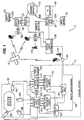
- Figure 1 is a diagram of the network and equipment for providing interactive digital programming.
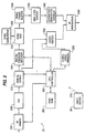
- Figure 2 is a block diagram of an interactive digital cable box of the present invention.
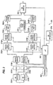
- Figure 3 is a block diagram of a dual-tuner interactive digital cable box allowing seamless switching between video signals.
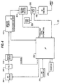
- Figure 4 is a block diagram of another interactive digital cable box allowing seamless switching between video signals.
- Figure 5 is a time diagram showing a representation of trigger points and corresponding video, audio and/or graphics segments, one or a combination of which are selected for presentation to the subscriber immediately after the execution of the trigger point function.
- Figure 6 is a block diagram of an alternative embodiment of an interactive system including internet access.
- Figure 7 is a block diagram of a two-way configuration of the system.
- an interactive digital system 1 for producing a personalized program allowing the home viewer an expanded set of programming options.
- Digital TV steams are put into digital packages made up of video, audio, data codes and graphics, and are used to provide personalized responses to viewer selections. Such responses may be further enhanced by allowing access to Internet Web sites 170. In this manner, sports such as golf, football, baseball, basketball, etc. can be watched with greater interest and involvement.
- Super Bowl coverage typically encompasses 25 to 30 cameras.
- These live video streams can be integrated with recorded video streams which, for example, may include highlights from the current game or past games, player profiles, etc.
- the interactive broadcast program is prepared at the control studio 5 into digital packages.
- the control studio 5, as shown in Figure 1, allows a producer to create and introduce interactive elements during a live broadcast.
- the producer pre-records a set of interrogatories or instructions for the user. These interrogatories may include such questions as the following: SELECT THE CAMERA ANGLES/OPTIONS THAT YOU PREFER:
- Such interrogatories can be presented to the viewer at the beginning of the broadcast or scattered throughout the program.
- Interactive responses to such interrogatories would include video, audio and graphics personalized to the particular viewer.
- the preparation of the graphics for presenting such interrogatories occurs off-line at the control studio 5 using chyron or any graphics language.
- These interrogatories or instructions will ultimately be displayed to the home viewer, preferably in the form of graphics, to facilitate the interactive responses.
- the producer creates these graphic video slides of questions on a computer using the text editor and chyron. Associated with each question, the producer enters a number of possible viewer options. Then, the producer relates each possible user entry to one or more corresponding interactive responses.
- the producer will indicate the particular Uniform Resource Locator (URL) of the Web page.
- the producer sets a time stamp for when each particular question will appear during the program.
- the viewer response to a query will be used to direct which video (and/or audio, graphics, or Web page) option will be provided to the viewer.
- the interactive response to the query can occur immediately following the entry of the viewer entry or at some predetermined later time in the program using "trigger points," 500 as explained in detail below.
- cameras 100 are preferably trained on different segments of the sporting event 10. As is common with broadcasts of a football game, for example, cameras 100 could be located in the endzone, press box, the field and at various other locations throughout the stadium. Further, various video options can be created including video replay, slow motion, isolation on cheerleaders, particular player or group of players. Instant replays are created by delaying the live feed for a certain number of seconds. These video streams are sent to a control studio 5.
- the control studio 5 contains the necessary equipment for packaging the program for delivery to the viewers.
- the studio 5 contains a video switcher 105 which receives the live signals from the cameras 100 by way of various input lines.
- lines carrying recorded video streams from one or more VCRs 110, computers or CD players feed into the video switcher 105.
- the video switcher 105 also receives video inputs from the control computer 135. Further, various graphics screens, depicting, for example, sports team or player statistics can be designed with the control personal computer 135 and forwarded to the digital video switch 105.
- the producer via the control PC 135, directs which video options to pass through the video switcher 105.
- each of the different output video streams access a separate encoder 125 and are all GENLOCKED, so that each video stream is synchronized with the other video streams.
- the video streams are input into a video compressor 125.
- the digital compression scheme is MPEG-2.
- 64 Quadrature Amplitude Modulation (QAM) is used as the modulation scheme.
- QAM Quadrature Amplitude Modulation
- four channels of digitally-compressed video content would carry about 27 Mbps using 6 MHz of bandwidth.
- 256 QAM seven-to-one video compression can be achieved with the MPEG-2 scheme.
- MPEG-2 is the preferred compression scheme
- the signals can be compressed according to any known standard including MPEG-1, JPEG, or other DCT coding scheme, wavelets, fractals or other transform or waveform based technique.
- the control studio 5 also contains an audio switcher 115 which receives live audio signals from microphones or recorded audio from tape players 120, CDs, VCRs 110, etc..
- the control computer 135 sends commands to the audio switcher 115 directing which audio options should pass through the switch 115. Further, in the audio switcher 115 the various audio signals can be aligned to match the various video signals in time.
- VCR audio output is received by the audio switcher 115.
- the present invention can accommodate any number of audio signals as output from the audio switcher 115, as directed by the producer.
- the audio outputs are received by an digital audio encoder/compressor 130.
- the audio signals are then preferably sampled, encoded and compressed in the digital audio encoder/compressor 130.
- the encoding technique can be a waveform coding technique such as PCM, ADPCM or DM.
- the signals can be encoded using synthesizer or vocoder techniques such as MUSICAM, Linear Predictive Coding (LPC), Adaptive Predictive Coding (APC), and Sub-band coding.
- LPC Linear Predictive Coding
- API Adaptive Predictive Coding
- Sub-band coding Generally, the transmission rate is about 256 kbps per audio for the stereo pair.
- the timing and control for integrating the various multimedia elements is provided by the ACTV authoring language, a unique set of interactive data codes to facilitate the interactive process.
- the data codes are stored in memory in the control computer 135 as part of the ACTV programming language.
- the codes comprise commands, or branch codes, for branching between interactive options, timing signals for controlling the interactive program, data or text, commands for termination and initiation or interactive program viewing, or triggers for executing macros.
- these commands are output from the control computer 135 and multiplexed with the video streams in the MPEG-2 compressor 125, as shown in Figure 1.
- Interactive options that can be branched to based on the branch codes include video segments, audio segments, graphics segments and/or identified Web pages.
- the digital interactive system 1 uses an interactive program delivery system with any transmission means including satellite 15, cable 150, wire or television broadcast 175 to deliver the interactive program (hereinafter "composite interactive program") from the control studio 5 for distribution to subscribers in their homes.
- the signals from the digital multiplexer 140 are converted to RF and distributed to a microwave 175, cable 150 or satellite 15 network.
- the digital interactive signal is forwarded from the control studio 5 to a cable headend 150, and subsequently, sent to the homes via the cable network.
- the program is preferably the broadcast of a live event.
- live sporting events with added interactive elements can be broadcast from the control studio 5.
- live interactive elements could be different camera angles 100, slow motion video, etc., as discussed above, while also incorporating prerecorded interactive segments such as highlights.
- the program can be produced off-line and stored in a program storage means at the control studio 5.
- the digital interactive signals are transmitted to uplink equipment where they may be multiplexed, upconverted, modulated, amplified and transmitted by satellite 15 to the receiver site 155 for distribution to the homes.
- the composite digital interactive signals enter a receiver 155 where the signals are demultiplexed, downconverted, demodulated and then passed to a cable distribution system that directs the signals to the homes.
- a cable distribution system 150 is the preferred transmission media to the homes, the digital signals may also be distributed by any conventionally known technique including satellite 15 to digital satellite receivers 155 at the home, fiberoptics, low or high power broadcast television 175, telephone lines, cellular networks, and similar technology can be used interchangeably with this program delivery system.
- the interactive digital box 25 is shown schematically in Figure 2.
- the interactive digital box is a specially adapted digital cable box 25.
- the controller 260 determines what video, audio, graphics and/or Web pages to display based upon the interactive commands which it receives. Based upon the commands, it plays the appropriate video, audio, graphics or Web page options.
- the graphics can either be created and sent from the control studio 5 or the graphical images can be created at the interactive digital box 25 based on instructions preferably in the interactive commands.
- the interactive digital box 25 connects to a television 165 or other display monitor. Further, the interactive digital box 25 can be connected to a digital television 195, in which case an RF modulator 245 is not necessary. Each downstream transmission reaches the subscriber's house, shown in Figure 2, preferably through a tap and drop cable.
- the user interacts with the program through the input device 20.
- the input device 20 is a typical television remote.
- the user interface 270 may be an infrared, wireless, or wired receiver that receives information from the input device 20.
- user inputs can be utilized by the present invention immediately, or at a later time, to result in personalized graphics, video and/or audio presentation.
- the present invention utilizes "trigger points," 500 as described below, to enable subsequent branches among multimedia segments during the show.
- commands are sent from the control studio 5 as part of the digital interactive programming to facilitate the collection of user entries. These commands are extracted at the digital demultiplexer 210 and sent to the controller 260 which performs the appropriate action based on the commands. Some of these commands are explained below.
- Other commands include those which allow for the following applications: (1) viewer profiling, to enable the set top box 25 to "remember" viewer preferences; (2) uploading viewer responses to a central location; (3) downloading of text and graphics, for display using the graphics chip of the set top box 25; (4) the ability of the viewer to prepare his own video, based upon his selections of camera shots 100 and audio, which can be stored and replayed for the viewer.
- the interactive digital box 25 of the present invention enables seamless flicker-free transparent switching between the digital video signals. "Seamless" means that the switch from one video signal to another is user imperceptible. Because the video signals are running off the same clock, the interactive digital box 25 is capable of providing a seamless digital switch from one video signal to another signal.
- the program clock reference necessary for the box to make this seamless switch is preferably embedded in the signal header.
- a CPU 260 is connected to an RF demodulator 200 and digital demultiplexer 210.
- the CPU 260 directs demodulation and demultiplexing of the proper channel and data stream to obtain the correct video signal. Seamless switching can occur with MPEG-2 compressed signals since there are points within the frame wherein seamless switching can occur. Preferably, switches occur at an "I" frame, assuming the use of MPEG-2 compression.
- the selected video signal is determined either by examination of the user's input from user interface 270 and/or any other information or criteria (such as personal profile information) stored in RAM/ROM 265.
- the RAM/ROM 265 could store commands provided within the video signals as discussed in U.S. patent no. 4,602,279.
- the RF demodulator 200 demodulates data from the broadcast channel directed by the controller 260. After the data stream is demodulated, it passes through a forward error correction circuit 205 into a digital demultiplexer 210. The demultiplexer 210 is controlled by the controller 260 to provide a specific video signal out of a number of video signals which may be located within the data stream on the demodulated broadcast channel. The demultiplexed video signal is then decompressed and decoded by decompressor/decoder 215. The video signal is synchronized by a sync add circuit 220 and a sync generator 225. The video signal is then buffered by a video frame buffer 230. The buffered video signal is modulated by a modulator 245 into a NTSC compatible signal. Such a modulator is not necessary if the selected signal is sent to a digital television 195.
- the decompressor/decoder 215 By using a video frame buffer 230 and delaying the viewing of a given signal, enough time is allowed for the decompressor/decoder 215 to lock onto, decompress, convert to analog, and wait for the resultant vertical interval of a second video signal.
- video signal A is currently being processed and transferred through the circuit shown in Figure 2 and displayed.
- the controller 260 directs the digital demultiplexer 210 and RF demodulator 200 to switch to another video signal, video signal B.
- the analog video from the first digital video signal, video signal A complete with video sync, is fed into video frame buffer 230.
- This buffer 230 can hold the full video picture for "n" number of frames after which the signal is output to the display.
- a delayed video signal A is viewed "n" number of frames after the signal has been received.
- the controller 260 instructs the digital demultiplexer 210 to stop decoding signal A and lock onto signal B to begin decoding signal B instead of signal A.
- VBI vertical blanking interval
- the size of the buffer 230 has to be large enough so that this processing can take place without interruption during the switching of the video signals. If desired, the system may continue to use the buffer in anticipation of a future switch. By using the controller 260 to manipulate the fill and empty rate of the buffer 230, the buffer 230 may be rapidly filled with video signal B frames and then after a period of time will be reset and ready to make another switch to another video in the same manner.
- the buffer 230 may also be reset by skipping frames or providing a delay between sequential frame outputs for a short time in order to fill the buffer 230. If a delay is used to maintain video signal or frame output while the buffer 230 is being filled, a slight distortion may occur for a brief amount of time.
- the buffered video masks the acquisition and decoding of a second video signal. As long as the buffer 230 is large enough to keep the first video running while the second video is being decompressed and decoded, a seamless switch will occur.
- While the digital interactive box 25 of Figure 2 provides video interactivity, audio and/or graphics interactivity is also provided. For example, if, based on the viewer profile or viewer response to query, it is determined that the viewer's primary language is Spanish, then that viewer could obtain Spanish commentary to the football, soccer, etc. game. Alternatively, if a viewer has a favorite athlete, the audio can switch to an interview with the athlete during a segment of the broadcast. Multiple digital audio options forming a set of suitable responses to an interrogatory message can be sent as part of the composite digital signal. As set forth in U.S. patent no. 5,585,858, there are a number of different ways to effectively forward the necessary audio options for a given live event to the digital interactive box 25. With the present invention, it makes no difference how the audio options reach the digital interactive box 25, as long as they are available for selection and play at the appropriate times.
- the digital demultiplexer 210 extracts the digital audio signal(s) and forwards them to the audio switch 250. Additional audio options are available from the digital audio memory 255. At certain times during the program, the data codes will identify the selection of a particular audio option corresponding to previous user inputs.
- the controller 260 calls the appropriate audio options from internal memory 255 or directs the audio switch 250 to select a predetermined audio segment received as part of the received digital signal for passage to the RF modulator 245 for play to the subscriber. At the end of the audio segment time period as indicated by the data codes, the controller 260 instructs the audio switch 250 to again pick up standard audio.
- the digital demultiplexer 210 sends the extracted graphics data or ACTV data codes to the controller 260.
- the controller 260 interprets the extracted data as either control data, including instructions for switching between video signals, audio signals, or graphics data for on-screen display. if the data is on-screen display data, the data is preferably prefixed by a command designating the data as on-screen display data, as opposed to control data. Further, the controller 260 also examines the control data for the occurrence of a header code designating the onset of a trigger point 500 in the program, explained below.
- FIG. 3 shows an alternate, dual tuner embodiment for seamless switching between separate video signals.
- This embodiment presumes that two 6 MHz channels are used, each of which comprises compressed digital video and audio streams.
- the microprocessor 260 controls the selection of the RF channel that is demodulated by RF demodulators 200A, 200B.
- the demodulated data streams enter the forward error correctors 205A, 205B.
- the forward error correctors 205A, 205B At the output of the forward error correctors 205A, 205B the data streams are transmitted to the input of the digital demultiplexers 210A, 210B.
- the digital demultiplexers 210A, 210B are controlled by the microprocessor 260.
- This configuration allows the microprocessor 260 to independently select two different individual time-multiplexed video signals on different channels and data streams. If all the video signals of an interactive program were contained on a single channel or data stream, it would only be necessary to have a single RF demodulator 200, forward error corrector 205, and digital demultiplexer 210 serially connected and feeding into the two digital video buffers 230A, 230B.
- Two data streams are provided from the digital demultiplexers 210A, 210B
- One data stream carries video information pertaining to the video signal the user is currently viewing.
- the second data stream carries the video signal selected based on the user's previous and/or current interactive selections from the user interface 270, as determined by the microprocessor 260.
- the digital information on each of the two streams is buffered in digital video buffers 230A, 230B.
- the buffered signals are then decompressed and converted into analog signals by decompressors/decoders 215A, 215B which include digital to analog converters.
- the decompressors 215A, 215B are preferably MPEG-2 decoders.
- a local sync generator 225 is connected to sync add 220A, 220B and frame sync 380A, 380B circuits. Because both streams are synchronized based on signals from the same local sync generator 225, each stream becomes synchronized to the other. In particular, the signals on each stream are frame synchronized.
- a vertical blanking interval (VBI) switch 335 is connected to the microprocessor 260 so that the input may be switched during the vertical blanking interval of the current stream, resulting in a seamless switch to the viewer.
- the embodiment of Figure 3 operates as follows. Based on user responses and control codes, it is assumed that the microprocessor 260 determines that a switch from video signal A to video signal C should be performed.
- the RF demodulator 200A and digital demultiplexer 210A are processing the currently viewed video signal, video signal A, which is progressing through the upper branch components.
- a command is issued from the microprocessor 260 to the RF demodulator 200A, 200B commanding a switch to the channel and data stream on which video signal C is located.
- the microprocessor 260 also instructs the digital demultiplexer 210B to provide video signal C from the received data stream to digital video buffer 230B.
- the upper RF demodulator 200A and digital demultiplexer 210A are still independently receiving and processing video signal A, which continues through the upper branch of the circuit.
- the digital decompressor/decoder 215B in the lower branch will begin filling up with video signal C frames. After video signal C is decompressed and decoded, it is converted into analog.
- a local sync generator 225 inserts both local sync and frame sync to video signal C via sync add circuit 220B and frame sync circuit 380B in order to synchronize it with the currently displayed video signal A, which is still being provided from the upper digital video buffer 230A.
- the microprocessor 260 directs the VBI switch 335 to switch in the vertical blanking interval from video A to video C, at which time video C will then seamlessly appear on the computer screen.
- Digital video buffers 230A, 230B may be used in the circuit of Figure 3, but are optional. However, in an alternative embodiment the buffers would be required to provide a seamless switch if the Figure 3 circuit was modified to incorporate a single RF demodulator 200, single forward error corrector 205, and single digital demultiplexer 210, each with a single input and single output. In this alternative embodiment, the circuit cannot independently receive and demultiplex two data streams on different frequency channels.
- One buffer 230A is used to store previously received video signals, while the other buffer 230B quickly passes through the selected video signals.
- video signal A is progressing through the upper branch of the circuit and it is desired to switch to video signal C.
- the digital video buffer 230A is providing maximum buffering to video signal A.
- the microprocessor 260 directs the alternative circuit (containing a single RF receiver 200, single forward error corrector 205 and single digital demultiplexer 210 connected in serial), to receive and demultiplex the data stream on which video signal C is located, which may be different than that of video signal A.
- the microprocessor 260 directs the digital video buffer 230 to provide minimum buffering of video signal C so that decompressor/decoder 215 may quickly decompress and decode the digital signals.
- video signal C is synchronized with video signal A. At this time, video signal A is read for display from digital video buffer 230A.
- the upper digital video buffer 230A must be large enough to provide video frames for output during the time it takes the RF demodulator 200 and digital demultiplexer 210 to switch to video signal C and the time required for decompression, decoding, and synchronization of video signal C.
- the microprocessor 260 directs VBI switch 335 to switch from video signal A to video signal C in the vertical blanking interval of video signal A, thereby providing a seamless and flicker-free switch.
- digital video buffer 230 will begin to utilize maximum buffering by altering its fill/empty rate as described above with respect to the Figure 3 embodiment.
- a switch to another video signal may be performed in the same manner as described above.
- FIG. 4 Another preferred embodiment is shown in Figure 4.
- This embodiment also includes an RF demodulator 200, a forward error corrector 205, and a digital demultiplexer 210.
- the circuitry differs along the rest of the chain to the television set or monitor.
- a memory 475 is incorporated and connected to the output of the demultiplexer for storing the compressed composite digital video signal.
- the decompressor/decoder 215 is inserted at the output of the compressed memory. The decompressor/decoder 215 decompresses the digital signal, converts the signal to analog and forwards the analog signal to the RF encode 245 for transmission to the monitor.
- the microprocessor 260 directs a pointer to be placed somewhere along the compressed digital video signal. Based on the placement of the pointer, different frames and different segments of the composite digital video signal will be read from memory 475 for decompression and decoding.
- the different video signals are distinguished from one another because they are labeled, preferably by headers.
- the compressed digital memory 475 fills up with A frames.
- the microprocessor 260 directs the RF demodulator 200 and digital demultiplexer 210 to begin filling the compressed memory 475 with video C frames.
- the decoder 215 pointer begins to move down. As soon as a sufficient number of C frames have entered the compressed memory 475, the pointer will then jump to the beginning of the C frames.
- the C frames are then output into the decompressor/decoder 215 where the digital frames are converted into an analog signal.
- the digital video is multiplexed in a series of easily identifiable packets. These packets may contain full compressed frames of video (I frames) or may include only the differences between full frames (B frames or P frames).
- the decompressor/decoder 215 needs to have a minimum number of I, P and B frames.
- the decoder 215 needs only one I frame to decode an image.
- two prior Anchor frames (I's" and "P's) are necessary to decode B frames.
- the decoder 215 only needs one Prior Anchor frame.
- the microprocessor 260 starts to fill up the memory 475 with video signal C packets until it is determined that a full sequence of I, B and P frames are available.
- the decoder 215 should receive the last bit of the last B frame in a given, GOP (Group of Pictures) before the switch, in order to prevent glitches when decoding. Furthermore, the last B frame of the GOP must only be backward predicted, not forward predicted or bidirectional predicted.
- the microprocessor 260 moves the memory read pointer to the start of a valid sequence of C video signal packets so that the decompressor/decoder 215 can successfully decode the C signals. This results in a seamless switch from video signal A to video signal C.
- This embodiment requires a data channel for enabling a synchronous switch between a first video stream and a second video stream.
- This data channel comprises the ACTV codes which link together the different program elements and information segments on the different video signals.
- the data channel also comprises synchronization pulses and a time code to signify to the pointer the proper time to skip from a memory location representing one video signal to a memory location representing another video signal in order to enable a seamless switch.
- the microprocessor 260 reads the data signal from the digital demultiplexer 210 and communicates pertinent data to the sync add circuit 220, which is connected to sync generator 225. The microprocessor 260 is then able to synchronously communicate with the memory 475.
- the time code sent will identify the timing for one picture, as well as for multiple pictures, and will lock the different pictures together. This is done through the use of similar clocks at both the transmission end and the receiver. A time code is used in order to keep the two clocks at both the transmission and receive end synchronously connected to one another. Once the clocks at both ends are working synchronously, each of the multiplexed video streams must be synchronized to the clocks. In order to synchronize the multiplexed video stream to the clocks, each of the individual channels must be referenced to a common reference point and must be identified.
- a packet header would be incorporated into the transport layer of the MPEG signal to identify the various channels.
- the packet header will also include information as to where to insert the vertical blanking interval.
- the vertical blanking interval is not transmitted from the headend. Therefore, the vertical blanking interval must be generated locally.
- the packet header eye will identify at what time the vertical blanking interval is in existence in order to effectuate a seamless switch between analog pictures.
- the combination of clock and the information embedded in either the transport layer of MPEG or in a separate packet on a separate data channel effectuates the linking between each video signal and a corresponding time point.
- the data channel also includes information designating when all the various video signals will be in synchronism with one another. It is at these points that the microprocessor 260 may direct the pointer to skip from one location to another location, at a time (such as during the VBI) when a seamless switch will result.
- trigger points 500 are scattered at various predetermined times throughout the program, a timeline representation of which is shown in Figure 5.
- the trigger points 500 correspond to times when interactive events are scheduled to take place during the live sporting event 10.
- These interactive events could be the selection and playing of video, audio segments, the display of graphics or display of Web pages accessed from Internet Web sites 170. For example, when a viewer's favorite baseball player is at bat, graphics showing past or current performance statistics of the player can be overlaid on the screen while excerpts from an interview with the player can be played for the viewer.
- the viewer selections in response to displayed graphical interrogatory messages are preferably made during a period at the onset of the program or when a viewer first tunes into the program.
- interrogatories are not necessary if the switches are based on the viewer profile stored in memory 265. These viewer selections are then utilized as inputs to macros called up at later times during the program by the controller 260 upon the occurrence of the trigger points 500, identified to the interactive computer by unique codes embedded in the video signal.
- the trigger points 500 correspond to the times when the conventional program content can be altered and personalized for the viewers.
- the programmer can place the trigger points 500 at any time throughout the program. Since the trigger points 500 are unknown to the subscriber, the subscriber does not know when they will receive a personalized message. In other words, an interactive response can either immediately follow a corresponding user selection made to an interrogatory message or occur at a later time corresponding to a trigger point 500, or any combination of the two.
- timing of the interactive events should correspond to suitable times in the program where branching to interactive elements is sensible and does not clash with the program content of the conventional video still displayed on the television 165 or other display monitor.
- the controller 260 will select one of several possible audio (or video or graphic display) responses for presentation to the subscriber. As mentioned above and shown in figure 5, some of the responses may comprise a branch to either a video segment, graphics and/or audio segments.
- the present invention allows for the viewer to select certain options at the onset of the program to suit the viewers' preferences. For example, if the program broadcast is a live sports event 10, at an early trigger point 500, the viewer could be queried as to whether the viewer would prefer to receive audio in English, Spanish, French, or perhaps hear the local announcer instead of the network announcer. Upon the viewer selection, the CPU 260 directs a branch to the appropriate interactive segment.
- Each trigger point 500 is identified preferably through the broadcast of ACTV codes sent as part of the composite interactive program signal.
- the codes preferably include, at a minimum, the following information: (1) header identifying the occurrence of a trigger point 500; (2) function ID (e.g., selection of audio or graphics responses, etc.); and (3) corresponding interrogatory message(s) or particular viewer characteristic or habit based on viewer profile.
- the first bit sequence simply identifies to the controller that a trigger point 500 is about to occur.
- the function ID designates the macro or other set of executable instructions for the controller 260 to read and interpret to obtain the desired result, e.g., a selected video and/or audio response.
- the controller 260 Upon extraction of the codes by the data decoder; the controller 260 reads and interprets the codes and calls from memory 265 a particular user selection(s) designated by the trigger point 500 codes.
- the user selections correspond to subscriber answers to a series of interrogatory messages preferably presented at the beginning of the program.
- the controller 260 After obtaining the appropriate user selection(s), the controller 260 reads and performs the executable instructions using the user selection(s) as input(s) in the macro algorithm.
- the result of the algorithm is either a selected video stream, audio and/or selected graphics response.
- the video/audio response can be called from memory 265 if it is prestored, called from external data storage, or the controller 260 can command the switch to branch to the particular video audio stream if the response is broadcast concurrently with the trigger point 500.
- the switch branches back to the standard program, shown at time t s in Figure 5.
- interrogatory messages are preferably presented when the subscriber begins watching the interactive program.
- These interrogatory messages can be presented in any one of three ways.
- the interrogatory messages can be presented as graphics displays overlaid by the interactive computer workstation onto a video signal, wherein the graphics data is sent in the vertical blanking interval of the composite interactive signal, or alternatively stored on the hard disk or external storage.
- the interrogatory messages are presented as graphics displays as discussed above, except the graphics data comes from local storage, external data storage (e.g., CD ROM, cartridge, etc.), or a combination of data in the VBI and data called from either local or external data storage.
- graphics data can be presented in the form of user templates stored at the interactive computer workstation.
- each interrogatory has a set of possible answers.
- Next to each possible answer will. be some identifier corresponding to a label on a key on the user interface. The subscriber depresses the key corresponding to their answer selection. This selection is decoded by the remote interface 270 and controller 260, stored in memory 265, preferably RAM, and used later as required by an algorithm designated at a trigger point 500.
- the Internet can be used as a source of personalized information for interactive responses.
- the video programming is preferably created at a centralized location, i.e., the control studio 5 as shown in Figure 1, for distribution to subscribers in their homes.
- the operator at the control studio 5 must designate certain Web pages to correspond to one of the program options, such as audio and/or graphics options, using control PC 135 and URL encoder 600.
- Web address identifiers i.e., Uniform Resource Locators (URLs) are encoded and sent as part of the data codes from the control PC 135 to the digital multiplexer 140. After multiplexing, the URLs are sent as part of the program signal 615, as described above.
- the URLs like the various audio and graphics options, have associated time stamps which indicate to the remote digital set top boxes 25 when, during the video program, to display the particular Web pages addressed by the URLs, the selection and display of which is preferably made as a function of viewer responses or viewer profile.
- each digital set top box 25 has an Internet connection 160 created concurrently with the cable connection.
- the Internet connection 160 can be via high-speed line, RF, conventional modem.
- the digital set top box 25 has Internet access 160 via any of the current ASCII software mechanisms.
- the digital demultiplexer 210 extracts the URLs along with the other data codes.
- a local URL decoder 605 at the user site extracts the URLs.
- a JAVA enabled browser as well as specialized software for performing part of the method of the present invention are installed on the interactive digital set top box 25.
- the JAVA enabled browser allows the interactive digital set top box 25 to retrieve the Web pages and is preferred software, since it is platform independent, and thus, enables efficient and flexible transfer of programs, images, etc., over the Internet.
- the specialized software acts as an interface between the video programming and the Internet functions of the present invention.
- the processor and software interprets these URLs and directs the JAVA enabled browser to retrieve the particular relevant Web pages, and synchronizes the retrieved Web pages to the video content for display on the television monitor 165 at the appropriate times.
- the viewer also has the capability to link to a channel website at will. For example, if a viewer is interested in purchasing a product described in an advertisement, by merely clicking on a button on their remote 20, the producer's Website could be accessed by Internet connection 160 and displayed to the viewer. The viewer could then either obtain more information about the product or order the product, if desired. As described above, this application is possible by sending the URL associated with the producer's Website to the digital cable boxes 25 as part of the interactive program. Upon selection by the viewer, the web browser, located either in the digital set-top box 25 or externally in a connected PC 610, can retrieve the Web pages. The specialized software then synchronizes the Web pages for video display.
- the interactive digital set top box 25 of the present invention also has the advantage of remembering subscriber responses and using these responses in choosing a video/audio response, and/or graphics interrogatory message, to present to the student.
- Memory branching is a technique of the present invention where the algorithm assembles video/audio responses and graphics interrogatory messages according to the current and previous user inputs. Memory branching is accomplished by linking video/audio streams and/or successive graphics interrogatory messages together in a logical relationship.
- the interactive digital set top box 25 contains logic (preferably, in the software algorithm) and memory 265 to store previous subscriber selections and to process these previous responses in the algorithm to control future video/audio stream selection, as well as future graphics message selection.
- the interactive digital cable box 25 can have a "viewer profile" stored in its memory 265.
- the accumulated profile of viewer characteristics and/or habits can be stored at the control studio 5 or cable headend. If the profile statistics are accumulated at some central location, they can also be sent to each viewer's home. On the other hand, if accumulated in memory 265 at each of the set top terminals 25, the data could be sent to the central location for storage and dissemination by way of the digital back channel. Decisions regarding personalized advertising and viewing can then be made for a viewer or class of viewers based on the accumulated parameters.
- the "viewer profile” preferably contains characteristics of the particular viewer at that subscriber location, such as sex, hobbies, interests, etc. This viewer profile is created by having the viewer respond to a series of questions. Alternatively, the viewer profiles could be created at a control studio 5 and sent to the interactive digital cable box 25. This information is then used by the cable box software to create a compendium of the viewer's interests and preferences -- i.e., a user profile. The stored user profile would be used in place of the question/answer format, and thus, dictate the branches to interactive segments of interest to the viewer.
- the interactive cable box 25 can be programmed to create a user profile of each viewer based on the selections made during one of the interactive programs. If the profile shows that a particular viewer does not enjoy violence, the system can automatically branch to another video signal at the commencement of a fight in a sports program. Furthermore, such a user profile could be modified or enriched over time based on selections made during future interactive programs. For example, the 'memory' technique described above can be used to modify the user profile based on user response over time.
- Event data is collected from the viewer when the following command is received and processed by the controller 260 in the interactive digital cable box 25:
- This command is used to enable events which can be utilized for profiling during a show.
- the events indicated in this command are those profiling events which are possible during the show.
- the enabled events may be either selected by the viewer during the show, or may be automatically enabled based upon viewer selections.
- the programming choices or interactive responses can be triggered based on the content of the viewer profile itself. For example, if the viewer profile suggests that the viewer is particularly interested in sports cars, a sports car commercial could be played for the viewer at a predetermined point in the program. As another application, if a viewer's profile indicates that the viewer is interested in cooking, whenever the viewer watches such a program, the user profile would trigger the interactive program to download recipes and either display such recipes on the screen or send the recipes to an attached printer.
- Viewer profile information can then be collected at the control studio 5 through polling of the viewer cable boxes 25 for viewer selection data.
- Special polling software is loaded into the digital set top box 25 for performing the polling functions.
- the invention allows for the digital set top boxes 25 to send back data on command from the control studio 5 or periodically.
- the command to initiate an upload of viewer profile data is as follows:
- UPLOAD_EXTENDED UPLOAD_IDENTIFIER VARIABLE_NAME [PHONE_NUMBER] UPLOAD_IDENTIFIER numeric constant identifying upload. VARIABLE_NAME PHONE_NUMBER name of variable to be uploaded string, that consists of numbers only, it can be omitted, if not needed.
- the statistics and other user profile information is preferably sent back to the control studio 5 by use of the back-channel.
- one channel could carry the standard video channel, with other channels carrying different camera angles 100 and/or close-ups of particular players.
- Other potential video options include instant replay, highlights, player statistics via graphic overlays, etc.
- Graphics presenting statistical information on the players can be constantly updated using the Chyron system.
- trigger points 500 can provide for seamless integration of such video options during the sporting event, based on either the viewer responses to interrogatories at the beginning of the program and/or on the digital viewer profile.
- the viewer can become the director with the present invention. For example, the viewer can choose which camera angles 100 to emphasize. In a broadcast of golf, the viewer can direct whether they desire to follow a particular player from hole-to-hole, focus on one particularly difficult hole. In this manner, the viewer can customize the sporting broadcast to meet his own interests.
- the viewer can act as a director to create their own video.
- the viewer selects various camera angles 100 at different times. These selections along with a time stamp, indicating the program time when each selection was made, are stored in memory 265.
- the processor 260 will automatically direct branching between the video channels according to the stored selections at the time stamp. In this manner, a music video can be created by the viewer.
- the viewing experience can be further enlightening for the viewer by implementing games and contests during the live sporting event 10.
- graphics overlays can be developed that query the viewer during the game.
- viewers can be queried with such interrogatories as the following:
- Each viewer's responses can be sent back to the control studio 5 for tabulation of scores.
- the responses are packaged at the digital cable box 25 and transmitted to the control studio 5 via the digital backchannel upon the UPLOAD EXTENDED command.
- tabulation of scores can take place at the digital cable box 25 through the utilization of certain software in memory 265.
- Each correct answer can correspond to a certain number of points.
- the interactive program preferably presents a graphic showing the viewer point total. If desired, advertisers could present special gift certificates for excellent performance in such games. The provision of such certificates would occur by displaying a certain code that a viewer can take to a store to receive the gift. In this manner, viewer interests in sports events can be enhanced.
- the viewer has the option with the present invention to block out viewing of certain events. For example, if the viewer is adverse to violence during a sporting event or other type program, the system can block out such options from the viewer with the following data commands:
- EVENT EVENT_NUMBER is a numeric constant.
- This command is used to implement certain actions (such as an automatic branch to another video channel in order to block out violent event, for example), as soon as the event arrives.
- ON_EVENT EVENT_NUMBER MACRO_NUMBER EVENT_NUMBER is a numeric constant. MACRO_NUMBER is a numeric constant.
- the live programming system of the present invention may be operated in a two way configuration, as illustrated in Figure 7.
- the various video signals are processed as previously described, being digitized and compressed at the control studio 5.
- the signals are then sent to a central switching station, or headend 30.
- each digital set-top box 760 relays viewer selections back to the remotely located switching station 30.
- the viewer selections are relayed by way of the digital back channel 770.
- the viewer selections may be relayed to the switching station 30 by any conventional means, such as two-way cable television, telephone or microwave transmission.
- the switching station 30 receives the viewer selection and routes the desired signal to a transmitter 750 which conventionally transmits the desired video down the appropriate digital cable channel for the particular viewer.
- a demultiplexer 710 demultiplexes the compressed signals and places each on a separate bus channel 725.
- a number of remote control interactive switches 730, 732, 734, 736 are connected to the video signal bus 725. Based on the viewer selections, an algorithm stored in memory 265 and under processor 260 control at the central switching station 30, a digital seamless switch is made and the selected video, audio and/or graphics are forwarded to the viewer home for display.
- Such a two-way embodiment could be implemented in a video dial tone or video server system.
- a single video channel 755 is necessary for each home. Once the viewer selection is received at the server site at the cable headend 30, a switch is made to the appropriate video stream and this stream is sent on the single channel 755 to the home.
- a signal is sent by way of the telephone line to the central switching station 30 which routes the desired signal of the interactive program over the user's telephone line so that a single link handles both the interactive choice being made at the receiver and the transmission of that choice from the headend 30 where the actual switching takes place in response to the interactive selection made at the receiver.
- the two-way link between the viewer and switching station 30 may be used for other purposes.
- demographic data may be transferred from the viewer to the broadcast network for commercial purposes, such as targeted advertising, billing, or other commercial or non-commercial purposes.
- While the present invention has been described primarily with respect to live events, and in particular sporting events, it has equal potential for enhancing content in other program categories.
- a viewer can become their own director of a murder mystery or other drama.
- the program will branch to alternative video/audio segments as a result of the user selections. In this manner, different viewers with different selections may end up with a different murderer at the conclusion of the broadcast.
- the interactive multimedia computer maximizes personalized attention and interactivity to subscribers in their homes in real time.
Abstract
Description
- The present invention relates to a viewer reception system and to a method of receiving interactive programming, and to a method and system for providing interactive programming.
- Interactive video and audio presentation systems are currently being introduced into the entertainment and educational industries. A prominent interactive technology that has been applied successfully in these industries is based on providing interactivity in a one-way system through the provision of multiple time-synched parallel channels of information. For example, U.S. patents nos. 4,264,925 and 4,264,924, both provide audio and video interactivity and disclose interactive television systems where switching among multiple broadcast or cable channels based on viewer selections provides an interactive capability.
- US-A-5,585,858 describes a system in which a television program, can be watched on any conventional television set as a normal program, but where the viewer has a special interactive program box connected to the television, a fully functional interactive program can be additionally provided. Each interactive viewer enjoys personalized audio responses and video graphics overlayed on the screen. The interactive program may be provided to television sets or to computers by cable, direct broadcast satellite, television broadcast or other transmission means, and may be analog or digital.
- WO-A-9637075 and US-A-5,600,368 describe an interactive television system where, at a receiver, the viewer may selectively switch between video signals. In the system of WO-A-9637075, a processor at the receiver directs the switch based on viewer selections and branching codes incorporated in the video signals.
- However, what is needed is an interactive presentation system for providing true video, audio and graphics interactivity with digital programs broadcast live. Such a system must efficiently package all the digital elements of the live interactive program at a centralized control studio and allow viewers at home to receive personalized interactive programming.
- According to a first aspect of the present invention, there is provided a viewer reception system for receiving interactive programming, the interactive programming comprising a plurality of synchronised and compressed, live and prerecorded, video signals and graphics signals, a plurality of compressed, live and prerecorded audio signals, and branching codes which have been multiplexed with said video, graphics and audio signals, and said viewer reception system comprising: a viewer interface for receiving viewer entries; processing means, responsive to the viewer interface, for determining which of the received video, graphics and audio signals to play; a demultiplexer for selecting and demultiplexing a specific video signal under the control of said processing means; a decompressor/decoder connected to the demultiplexer for decompressing the demultiplexed selected video signals; and a video frame buffer for receiving and delaying play of a received video signal whereby a seamless switch to a further video signal may be directed by said processing means at a predetermined, video switching time, the further video signal selected and the predetermined video switching time of the selection being a function of the branching codes; and display means for displaying the selected video signal; and wherein the display means is additionally arranged to display graphics signals extracted by said demultiplexer as directed by said processing means; and the viewer reception system further comprising: an audio switch connected to the demultiplexer for selecting and receiving a specific audio signal as directed by said processing means, whereby a switch to a further audio signal may be directed by said processing means at a predetermined, audio switching time, the further audio signal selected and the predetermined audio switching time being a function of the branching codes; and means for playing the audio signal selected.
- A receiver of an embodiment of the invention enables the viewer to actively participate in selecting digital video streams, associated with different camera angles, for example, and also to select audio and/or graphics segments. In addition, web pages from Internet web sites can be integrated into the program.
- Embodiments of the invention are particularly suited for the broadcasting of live events, such as sporting events. The viewer can appear to direct the camera shots by instantly changing among various camera angles, choose player interviews, or display associated statistical data on the team or players via graphics. In this manner, the system allows the individual subscriber to act as if he or she has control over how the program is directed and presented on their personal television set. In addition to selecting different camera angles, various audio options, closeups, slow motion, replays, graphics overlays, graphics or audio from web sites, etc., are all possible. Further, games may be integrated with the live sports programming to increase viewer interest.
- Thus, viewers can customize the content of programs. The interactive digital programming of the present invention is particularly advantageous for viewing live sporting events. Viewers are not limited to selecting from multiple camera angles, but may also call up player statistics on demand, for example. Cameras may be focused on different segments of an event. Further, video options may include video replay, slow motion effects, isolation on a particular player or group, etc. Changes are seamless, thereby adding to the effect that the viewer is directing the television show just as a director now does from a control room. In addition, with the invention, the viewer may also select the audio to accompany the video displayed. For example, the viewer may listen to a commentary in a selected language, or may substitute player interviews, for example, for the commentary.
- This "director" role by the viewer is possible due to the interactive technology described herein and is also due to the digital compression and transmission scheme which allows for much greater information throughput over a given bandwidth, allowing viewers to choose from angles that are already available but presently cut by the director.
- The digital interactive system is based upon branches which occur in the course of the full-motion video. Branches are real-time parallel paths that may be other full-motion video segments, graphics which are integrated into the video, audio segments, and/or retrieved web pages.
- Sometimes, the interactive digital system will act upon the viewer's response immediately; other times, it will utilize ACTV's unique "profiling" concept to act upon the response later. This technology enables the system to "remember" the viewer's responses and desires, and integrate them into the video, audio, graphics and/or web site information at a later point. For example, the viewer could specify at the beginning of a football game to isolate the offensive quarterback of a particular team. Thus, whenever the team of choice is on offense, the video isolation of the quarterback is displayed to the viewer automatically. Or, based on how a viewer has selected camera angles, replays, etc., over the past five minutes, the system acts to mimic these selections at later times during the program. The systems described herein may "learn" from the viewer how they want to view the game, and then continue viewer selection sequences made earlier.
- In another aspect, the present invention provides a system for providing interactive digital programming, comprising: means for receiving video signals from a plurality of video cameras, one or more of the cameras relaying a different predetermined view of a live event, the video receiving means also receiving prerecorded video signals; means for receiving audio signals corresponding to the live event, the audio receiving means also receiving prerecorded audio signals; means for generating one or more graphics signals; at least one digital compression device connected to the video receiving means, the audio receiving means, and said generating means, for digitally compressing the video, graphics and audio signals; processing means connected to the compression device, for creating a set of data commands corresponding to the audio, graphics and video signals, the data commands including branching codes; a digital multiplexer connected to the digital compression device, for multiplexing the video, graphics and audio signals, and the data commands into a combined digital program stream; and means for transmitting the combined digital program stream.
- In an embodiment, each of the video cameras may relay a different predetermined view of an event. Preferably, the combined digital program stream is formed at a central control studio. After receiving the video, audio, and graphics signals at the central control studio, these signals are digitized and compressed in digital video and audio compressors. These signals are then combined with the special data codes into the "digital package," and subsequently, transmitted, for example, over a cable distribution system. The special data codes are the keys to unlocking the interactive potential of the program.
- The invention also extends to a method for providing interactive digital programming, comprising the steps of: obtaining video signals from a plurality of video cameras, one or more of the cameras relaying a different view of a live event; obtaining prerecorded video signals; producing one or more audio signals corresponding to the live event; obtaining prerecorded audio signals; creating one or more graphics signals; digitally compressing the video, graphic and audio signals; producing a set of data commands which correspond to the audio, graphics and video signals, the data commands including branching codes; digitally multiplexing the video, graphics and audio signals, and the data commands into a combined digital program stream; and transmitting the combined digital program stream.
- The digital program signals are transmitted to a receive site by any suitable transmission means. Once received by a receive antenna, the digital program signals are passed along a digital cable television distribution system to the viewer homes. Further, some other signals or commercials can be inserted at the local head end. The signals are received and processed in a digital cable box. Selections of the video, audio, graphics display and/or web pages may be made as a function of immediate viewer entries, or to interrogatory responses presented at the beginning or during the program, or based on a prestored viewer profile. Once a decision is made to switch from one video option to another video option, the digital switch is performed seamlessly.
- As mentioned above, the program at predetermined times or immediately upon user entry may retrieve and branch to informative segments from web sites. For example, a viewer watching a sporting event may receive a stream of web pages which provide additional, specific information relating to a favorite player, team or perhaps the remaining schedule for the sports team, as examples. In addition, users may take advantage of the two-way capabilities of the Internet to respond to polls or to link to additional sites.
- Another Internet-based application allows advertisers to speak more directly to consumers by directly sending web pages to the consumer instead of merely displaying web addresses in their commercials. The particular advertising information from web sites may be targeted to viewers based on the viewer profile, stored either in the digital set top box or at the cable head end. Alternatively, web site access may be initiated by the viewer by simply clicking on the remote during the commercial. Thus, the viewers have the capability to individually select web sites if they want more information from advertisers.
- The video programming and corresponding Internet pages may be viewed on personal computers equipped with a television card, on special digital cable boxes with stored interactive Internet application software providing Internet access, or on digital television sets.
- According to a further aspect of the present invention there is provided a method for receiving interactive programming, the live interactive programming comprising a plurality of digitally compressed video, audio, and graphics signals and branching codes, the method comprising the steps of: selecting one of the video signals and directing a seamless switch to the selected video signal at a first predetermined time, the selection of the video signal and the first predetermined time of the selection being a function of the branching codes; selecting one of the audio signals and directing a switch to the selected audio signal at a second predetermined time, the selection of the audio signal and the second predetermined time of the selection being a function of the branching codes; demultiplexing the selected video and audio signals; decompressing the demultiplexed selected video and audio signals; displaying the selected video signal; and playing the selected audio signal.
- Methods and systems of the invention also have application for other types of programming. For example, viewers can direct the scenes of a murder mystery. Switching from one scene to another can be done seamlessly without noticeable effect on the viewer. The invention may be utilised whether the television event is live or pre-recorded. For instance, a music concert or a political convention may be enhanced using techniques described herein.
- Embodiments of the present invention will hereinafter be described,
by way of example, with reference to the accompanying drawings, in which:- - Figure 1 is a diagram of the network and equipment for providing interactive digital programming.
- Figure 2 is a block diagram of an interactive digital cable box of the present invention.
- Figure 3 is a block diagram of a dual-tuner interactive digital cable box allowing seamless switching between video signals.
- Figure 4 is a block diagram of another interactive digital cable box allowing seamless switching between video signals.
- Figure 5 is a time diagram showing a representation of trigger points and corresponding video, audio and/or graphics segments, one or a combination of which are selected for presentation to the subscriber immediately after the execution of the trigger point function.
- Figure 6 is a block diagram of an alternative embodiment of an interactive system including internet access.
- Figure 7 is a block diagram of a two-way configuration of the system.
- There is described and illustrated herein, an interactive
digital system 1 for producing a personalized program allowing the home viewer an expanded set of programming options. Digital TV steams are put into digital packages made up of video, audio, data codes and graphics, and are used to provide personalized responses to viewer selections. Such responses may be further enhanced by allowing access toInternet Web sites 170. In this manner, sports such as golf, football, baseball, basketball, etc. can be watched with greater interest and involvement. - As shown in Figure 1, several possible video streams are gathered by way of
cameras 100, strategically located at asporting event 10, for example. In this respect, although the invention is described below with specific reference to the viewing of a live sporting event, it will be appreciated that the invention has many possible uses and the reference to a live sporting event is by way of example only. The present invention is not limited to use with live sporting events. - Currently,
many cameras 100 are employed at asporting event 10. Super Bowl coverage, for example, typically encompasses 25 to 30 cameras. These live video streams can be integrated with recorded video streams which, for example, may include highlights from the current game or past games, player profiles, etc. - The interactive broadcast program is prepared at the
control studio 5 into digital packages. Thecontrol studio 5, as shown in Figure 1, allows a producer to create and introduce interactive elements during a live broadcast. In one preferred embodiment, the producer pre-records a set of interrogatories or instructions for the user. These interrogatories may include such questions as the following:
SELECT THE CAMERA ANGLES/OPTIONS THAT YOU PREFER: - OPTIONS:
- END-ZONE
FIFTY YARD LINE
FOCUS ON THE QUARTERBACK
FOCUS ON THE DEFENSE
FOCUS ON THE CHEERLEADERS
PROVIDE HIGHLIGHTS - OPTIONS:
- BLUE TEAM
RED TEAM - OPTIONS:
- RED RUNNER
BLUE QUARTERBACK
BLUE DEFENSIVE END
RED QUARTERBACK
ETC. - Such interrogatories can be presented to the viewer at the beginning of the broadcast or scattered throughout the program. Interactive responses to such interrogatories would include video, audio and graphics personalized to the particular viewer. The preparation of the graphics for presenting such interrogatories occurs off-line at the
control studio 5 using chyron or any graphics language. These interrogatories or instructions will ultimately be displayed to the home viewer, preferably in the form of graphics, to facilitate the interactive responses. The producer creates these graphic video slides of questions on a computer using the text editor and chyron. Associated with each question, the producer enters a number of possible viewer options. Then, the producer relates each possible user entry to one or more corresponding interactive responses. If the response is information from an Internet Web page, the producer will indicate the particular Uniform Resource Locator (URL) of the Web page. The producer sets a time stamp for when each particular question will appear during the program. As explained below in more detail, the viewer response to a query will be used to direct which video (and/or audio, graphics, or Web page) option will be provided to the viewer. In the present invention, the interactive response to the query can occur immediately following the entry of the viewer entry or at some predetermined later time in the program using "trigger points," 500 as explained in detail below. - With respect to the video segments,
cameras 100 are preferably trained on different segments of thesporting event 10. As is common with broadcasts of a football game, for example,cameras 100 could be located in the endzone, press box, the field and at various other locations throughout the stadium. Further, various video options can be created including video replay, slow motion, isolation on cheerleaders, particular player or group of players. Instant replays are created by delaying the live feed for a certain number of seconds. These video streams are sent to acontrol studio 5. Thecontrol studio 5 contains the necessary equipment for packaging the program for delivery to the viewers. Thestudio 5 contains avideo switcher 105 which receives the live signals from thecameras 100 by way of various input lines. Further, lines carrying recorded video streams from one ormore VCRs 110, computers or CD players feed into thevideo switcher 105. Thevideo switcher 105 also receives video inputs from the control computer 135. Further, various graphics screens, depicting, for example, sports team or player statistics can be designed with the control personal computer 135 and forwarded to thedigital video switch 105. The producer, via the control PC 135, directs which video options to pass through thevideo switcher 105. At the output of thevideo switcher 105, each of the different output video streams access aseparate encoder 125 and are all GENLOCKED, so that each video stream is synchronized with the other video streams. - After encoding, the video streams are input into a
video compressor 125. Preferably, the digital compression scheme is MPEG-2. Preferably, 64 Quadrature Amplitude Modulation (QAM) is used as the modulation scheme. In this digital embodiment, four channels of digitally-compressed video content would carry about 27 Mbps using 6 MHz of bandwidth. Alternatively, if 256 QAM is employed, seven-to-one video compression can be achieved with the MPEG-2 scheme. While MPEG-2 is the preferred compression scheme, the signals can be compressed according to any known standard including MPEG-1, JPEG, or other DCT coding scheme, wavelets, fractals or other transform or waveform based technique. - The
control studio 5 also contains an audio switcher 115 which receives live audio signals from microphones or recorded audio from tape players 120, CDs,VCRs 110, etc.. The control computer 135 sends commands to the audio switcher 115 directing which audio options should pass through the switch 115. Further, in the audio switcher 115 the various audio signals can be aligned to match the various video signals in time. In addition, VCR audio output is received by the audio switcher 115. The present invention can accommodate any number of audio signals as output from the audio switcher 115, as directed by the producer. The audio outputs are received by an digital audio encoder/compressor 130. The audio signals are then preferably sampled, encoded and compressed in the digital audio encoder/compressor 130. The encoding technique can be a waveform coding technique such as PCM, ADPCM or DM. Alternatively, the signals can be encoded using synthesizer or vocoder techniques such as MUSICAM, Linear Predictive Coding (LPC), Adaptive Predictive Coding (APC), and Sub-band coding. Generally, the transmission rate is about 256 kbps per audio for the stereo pair. - The timing and control for integrating the various multimedia elements is provided by the ACTV authoring language, a unique set of interactive data codes to facilitate the interactive process. The data codes are stored in memory in the control computer 135 as part of the ACTV programming language. The codes comprise commands, or branch codes, for branching between interactive options, timing signals for controlling the interactive program, data or text, commands for termination and initiation or interactive program viewing, or triggers for executing macros. Preferably, these commands are output from the control computer 135 and multiplexed with the video streams in the MPEG-2
compressor 125, as shown in Figure 1. Interactive options that can be branched to based on the branch codes include video segments, audio segments, graphics segments and/or identified Web pages. - There are several commands in the ACTV authoring language that function to provide the interactive sports programming applications. These commands are explained below in Section D, which details programming applications.
- As shown in figure 1, the digital
interactive system 1 uses an interactive program delivery system with any transmissionmeans including satellite 15,cable 150, wire ortelevision broadcast 175 to deliver the interactive program (hereinafter "composite interactive program") from thecontrol studio 5 for distribution to subscribers in their homes. At thecontrol studio 5, the signals from thedigital multiplexer 140 are converted to RF and distributed to amicrowave 175,cable 150 orsatellite 15 network. Preferably, the digital interactive signal is forwarded from thecontrol studio 5 to acable headend 150, and subsequently, sent to the homes via the cable network. - The program is preferably the broadcast of a live event. For example, live sporting events with added interactive elements can be broadcast from the
control studio 5. Such live interactive elements could be different camera angles 100, slow motion video, etc., as discussed above, while also incorporating prerecorded interactive segments such as highlights. Alternatively, the program can be produced off-line and stored in a program storage means at thecontrol studio 5. - In a satellite broadcast transmission, the digital interactive signals are transmitted to uplink equipment where they may be multiplexed, upconverted, modulated, amplified and transmitted by
satellite 15 to thereceiver site 155 for distribution to the homes. - At the reception end, the composite digital interactive signals enter a
receiver 155 where the signals are demultiplexed, downconverted, demodulated and then passed to a cable distribution system that directs the signals to the homes. Although acable distribution system 150 is the preferred transmission media to the homes, the digital signals may also be distributed by any conventionally knowntechnique including satellite 15 todigital satellite receivers 155 at the home, fiberoptics, low or highpower broadcast television 175, telephone lines, cellular networks, and similar technology can be used interchangeably with this program delivery system. - The interactive
digital box 25 is shown schematically in Figure 2. Preferably, the interactive digital box is a specially adapteddigital cable box 25. Thecontroller 260 determines what video, audio, graphics and/or Web pages to display based upon the interactive commands which it receives. Based upon the commands, it plays the appropriate video, audio, graphics or Web page options. The graphics can either be created and sent from thecontrol studio 5 or the graphical images can be created at the interactivedigital box 25 based on instructions preferably in the interactive commands. The interactivedigital box 25 connects to atelevision 165 or other display monitor. Further, the interactivedigital box 25 can be connected to adigital television 195, in which case anRF modulator 245 is not necessary. Each downstream transmission reaches the subscriber's house, shown in Figure 2, preferably through a tap and drop cable. - The user interacts with the program through the
input device 20. Preferably, theinput device 20 is a typical television remote. Theuser interface 270 may be an infrared, wireless, or wired receiver that receives information from theinput device 20. - Regardless of the type of
input device 20, user inputs can be utilized by the present invention immediately, or at a later time, to result in personalized graphics, video and/or audio presentation. For example, the present invention utilizes "trigger points," 500 as described below, to enable subsequent branches among multimedia segments during the show. - Certain commands are sent from the
control studio 5 as part of the digital interactive programming to facilitate the collection of user entries. These commands are extracted at thedigital demultiplexer 210 and sent to thecontroller 260 which performs the appropriate action based on the commands. Some of these commands are explained below. - a. BEGIN INPUT EXTENDED The Begin Input command starts an input period during which the user
may press one or more buttons to select his or her choice(s). The entry
format of this command is set forth as follows:
BEGIN INPUT {{N} {VALID KEYS} {DIFFERENT} {FEEDBACK}
where:- N
- The maximum number of keys that can be pressed.
- KEYS
- The valid keys that can be pressed.
- DIFFERENT
- Requires each key pressed to be different.
- FEEDBACK
- The feedback type provided to the viewer.
- b. BEGIN VIDEO CHOICE EXTENDED The Begin Video Choice begins an input period for disco mode. During
disco mode, the video switches dynamically each time the viewer makes a
selection.
BEGIN_VIDEO_CHOICE MODE [KEYS] {FEEDBACK [AUDIO]}The disco mode allows the viewer to change channels at will, while the OneShot mode allows only one change of channel.- MODE
- DISCO/ONESHOT
- KEYS
- The valid keys that can be pressed.
- FEEDBACK
- The feedback supplied to the user for the key(s) which are pressed.
- c. BEGIN AUDIO CHOICE EXTENDED The Begin Audio Choice begins an input period for disco mode.
BEGIN_AUDIO_CHOICE MODE [KEYS] {FEEDBACK [AUDIO]}- MODE
- DISCO/ONESHOT
- KEYS
- The valid keys that can be pressed.
- FEEDBACK
- The feedback supplied to the user for the key(s) which are pressed.
- d. MAP The Map command is used to map video or audio tracks to keys, for use in
connection with the Begin Audio Choice and Begin Video Choice
commands. If this command is omitted,
Key 1 will map to Track orChannel 1,Key 2 to Track orChannel 2 etc. This command allows mapping any key to any channel.
MAP KEYS [TRACKS [T1,...TN/T1-TN] CHANNELS [C1,...CN/C1-CN]]The map statement maps audio tracks or video channels to keys, to enable audio or video choice commands to effect changes to tracks other than the default tracks, which are that key 1 maps to track 1,key 2 to track 2, etc.. All the choice statements after a map statement will cause the tracks, video tracks or channels to be changed to those specified in the map statement. The acceptable numbers for the map command are from 1 to 8, for keys, video channels and audio channels. -
- Other commands include those which allow for the following applications:
(1) viewer profiling, to enable the settop box 25 to "remember" viewer preferences; (2) uploading viewer responses to a central location; (3) downloading of text and graphics, for display using the graphics chip of the settop box 25; (4) the ability of the viewer to prepare his own video, based upon his selections ofcamera shots 100 and audio, which can be stored and replayed for the viewer. - The interactive
digital box 25 of the present invention enables seamless flicker-free transparent switching between the digital video signals. "Seamless" means that the switch from one video signal to another is user imperceptible. Because the video signals are running off the same clock, the interactivedigital box 25 is capable of providing a seamless digital switch from one video signal to another signal. The program clock reference necessary for the box to make this seamless switch is preferably embedded in the signal header. - As shown in Figure 2, a
CPU 260 is connected to anRF demodulator 200 anddigital demultiplexer 210. TheCPU 260 directs demodulation and demultiplexing of the proper channel and data stream to obtain the correct video signal. Seamless switching can occur with MPEG-2 compressed signals since there are points within the frame wherein seamless switching can occur. Preferably, switches occur at an "I" frame, assuming the use of MPEG-2 compression. The selected video signal is determined either by examination of the user's input fromuser interface 270 and/or any other information or criteria (such as personal profile information) stored in RAM/ROM 265. For example, the RAM/ROM 265 could store commands provided within the video signals as discussed in U.S. patent no. 4,602,279. - The RF demodulator 200 demodulates data from the broadcast channel directed by the
controller 260. After the data stream is demodulated, it passes through a forwarderror correction circuit 205 into adigital demultiplexer 210. Thedemultiplexer 210 is controlled by thecontroller 260 to provide a specific video signal out of a number of video signals which may be located within the data stream on the demodulated broadcast channel. The demultiplexed video signal is then decompressed and decoded by decompressor/decoder 215. The video signal is synchronized by async add circuit 220 and async generator 225. The video signal is then buffered by avideo frame buffer 230. The buffered video signal is modulated by amodulator 245 into a NTSC compatible signal. Such a modulator is not necessary if the selected signal is sent to adigital television 195. - By using a
video frame buffer 230 and delaying the viewing of a given signal, enough time is allowed for the decompressor/decoder 215 to lock onto, decompress, convert to analog, and wait for the resultant vertical interval of a second video signal. For example, assume video signal A is currently being processed and transferred through the circuit shown in Figure 2 and displayed. Based upon a user selection, thecontroller 260 directs thedigital demultiplexer 210 and RF demodulator 200 to switch to another video signal, video signal B. To accomplish this, the analog video from the first digital video signal, video signal A, complete with video sync, is fed intovideo frame buffer 230. Thisbuffer 230 can hold the full video picture for "n" number of frames after which the signal is output to the display. In effect, a delayed video signal A is viewed "n" number of frames after the signal has been received. When the user selects a different video path by means of pressing a button on a keypad or entry by other means, thecontroller 260 instructs thedigital demultiplexer 210 to stop decoding signal A and lock onto signal B to begin decoding signal B instead of signal A. - While this is happening, even though the decompressor/
decoder 215 is no longer decompressing video signal A, the display is still showing video signal A because it is being read from thebuffer 230. As soon as decompressing and decoding occurs, thecontroller 260 looks for the next vertical blanking interval (VBI) and instructs thevideo frame buffer 230 to switch to its input, rather than its buffered output at the occurrence of the VBI. - Since the
RF demodulator 200,forward error corrector 205,digital demultiplexer 210, and decompressor/decoder 215 require a certain time period to decompress and decode the video signal B frame from its data stream, the size of thebuffer 230 has to be large enough so that this processing can take place without interruption during the switching of the video signals. If desired, the system may continue to use the buffer in anticipation of a future switch. By using thecontroller 260 to manipulate the fill and empty rate of thebuffer 230, thebuffer 230 may be rapidly filled with video signal B frames and then after a period of time will be reset and ready to make another switch to another video in the same manner. Thebuffer 230 may also be reset by skipping frames or providing a delay between sequential frame outputs for a short time in order to fill thebuffer 230. If a delay is used to maintain video signal or frame output while thebuffer 230 is being filled, a slight distortion may occur for a brief amount of time. - Because a first video signal is always displayed as the output of the
buffer 230 after the delay, the buffered video masks the acquisition and decoding of a second video signal. As long as thebuffer 230 is large enough to keep the first video running while the second video is being decompressed and decoded, a seamless switch will occur. - While the digital
interactive box 25 of Figure 2 provides video interactivity, audio and/or graphics interactivity is also provided. For example, if, based on the viewer profile or viewer response to query, it is determined that the viewer's primary language is Spanish, then that viewer could obtain Spanish commentary to the football, soccer, etc. game. Alternatively, if a viewer has a favorite athlete, the audio can switch to an interview with the athlete during a segment of the broadcast. Multiple digital audio options forming a set of suitable responses to an interrogatory message can be sent as part of the composite digital signal. As set forth in U.S. patent no. 5,585,858,
there are a number of different ways to effectively forward the necessary audio options for a given live event to the digitalinteractive box 25. With the present invention, it makes no difference how the audio options reach the digitalinteractive box 25, as long as they are available for selection and play at the appropriate times. - In Figure 2, the
digital demultiplexer 210 extracts the digital audio signal(s) and forwards them to theaudio switch 250. Additional audio options are available from thedigital audio memory 255. At certain times during the program, the data codes will identify the selection of a particular audio option corresponding to previous user inputs. Thecontroller 260 calls the appropriate audio options frominternal memory 255 or directs theaudio switch 250 to select a predetermined audio segment received as part of the received digital signal for passage to theRF modulator 245 for play to the subscriber. At the end of the audio segment time period as indicated by the data codes, thecontroller 260 instructs theaudio switch 250 to again pick up standard audio. - The
digital demultiplexer 210 sends the extracted graphics data or ACTV data codes to thecontroller 260. Thecontroller 260 interprets the extracted data as either control data, including instructions for switching between video signals, audio signals, or graphics data for on-screen display. if the data is on-screen display data, the data is preferably prefixed by a command designating the data as on-screen display data, as opposed to control data. Further, thecontroller 260 also examines the control data for the occurrence of a header code designating the onset of atrigger point 500 in the program, explained below. - Figure 3 shows an alternate, dual tuner embodiment for seamless switching between separate video signals. This embodiment presumes that two 6 MHz channels are used, each of which comprises compressed digital video and audio streams. In this embodiment, the
microprocessor 260 controls the selection of the RF channel that is demodulated by RF demodulators 200A, 200B. The demodulated data streams enter theforward error correctors forward error correctors digital demultiplexers - As with the RF demodulators 200A, 200B, the
digital demultiplexers microprocessor 260. This configuration allows themicroprocessor 260 to independently select two different individual time-multiplexed video signals on different channels and data streams. If all the video signals of an interactive program were contained on a single channel or data stream, it would only be necessary to have asingle RF demodulator 200,forward error corrector 205, anddigital demultiplexer 210 serially connected and feeding into the twodigital video buffers - Two data streams are provided from the
digital demultiplexers user interface 270, as determined by themicroprocessor 260. - The digital information on each of the two streams is buffered in
digital video buffers decompressors - A
local sync generator 225 is connected to sync add 220A, 220B andframe sync local sync generator 225, each stream becomes synchronized to the other. In particular, the signals on each stream are frame synchronized. - A vertical blanking interval (VBI)
switch 335 is connected to themicroprocessor 260 so that the input may be switched during the vertical blanking interval of the current stream, resulting in a seamless switch to the viewer. - The embodiment of Figure 3 operates as follows. Based on user responses and control codes, it is assumed that the
microprocessor 260 determines that a switch from video signal A to video signal C should be performed. TheRF demodulator 200A anddigital demultiplexer 210A are processing the currently viewed video signal, video signal A, which is progressing through the upper branch components. A command is issued from themicroprocessor 260 to theRF demodulator microprocessor 260 also instructs thedigital demultiplexer 210B to provide video signal C from the received data stream todigital video buffer 230B. - At this point, the
upper RF demodulator 200A anddigital demultiplexer 210A are still independently receiving and processing video signal A, which continues through the upper branch of the circuit. - At a certain point, the digital decompressor/
decoder 215B in the lower branch will begin filling up with video signal C frames. After video signal C is decompressed and decoded, it is converted into analog. Alocal sync generator 225 inserts both local sync and frame sync to video signal C via sync addcircuit 220B andframe sync circuit 380B in order to synchronize it with the currently displayed video signal A, which is still being provided from the upperdigital video buffer 230A. At the appropriate switch point, triggered by programming codes supplied with each video signal A and C, themicroprocessor 260 directs theVBI switch 335 to switch in the vertical blanking interval from video A to video C, at which time video C will then seamlessly appear on the computer screen. -
Digital video buffers single RF demodulator 200, singleforward error corrector 205, and singledigital demultiplexer 210, each with a single input and single output. In this alternative embodiment, the circuit cannot independently receive and demultiplex two data streams on different frequency channels. Onebuffer 230A is used to store previously received video signals, while theother buffer 230B quickly passes through the selected video signals. - Based on the same assumptions above, video signal A is progressing through the upper branch of the circuit and it is desired to switch to video signal C. However, in this alternative embodiment, the
digital video buffer 230A is providing maximum buffering to video signal A. - Because it is desired to switch to video signal C, the
microprocessor 260 directs the alternative circuit (containing asingle RF receiver 200, singleforward error corrector 205 and singledigital demultiplexer 210 connected in serial), to receive and demultiplex the data stream on which video signal C is located, which may be different than that of video signal A. When video signal C is demultiplexed, themicroprocessor 260 directs thedigital video buffer 230 to provide minimum buffering of video signal C so that decompressor/decoder 215 may quickly decompress and decode the digital signals. After decompression and decoding, video signal C is synchronized with video signal A. At this time, video signal A is read for display fromdigital video buffer 230A. The upperdigital video buffer 230A must be large enough to provide video frames for output during the time it takes theRF demodulator 200 anddigital demultiplexer 210 to switch to video signal C and the time required for decompression, decoding, and synchronization of video signal C. - When video signal C is synchronized with video signal A, the
microprocessor 260 directsVBI switch 335 to switch from video signal A to video signal C in the vertical blanking interval of video signal A, thereby providing a seamless and flicker-free switch. - At this time,
digital video buffer 230 will begin to utilize maximum buffering by altering its fill/empty rate as described above with respect to the Figure 3 embodiment. When adequate buffering is achieved, a switch to another video signal may be performed in the same manner as described above. - Another preferred embodiment is shown in Figure 4. This embodiment also includes an
RF demodulator 200, aforward error corrector 205, and adigital demultiplexer 210. However, the circuitry differs along the rest of the chain to the television set or monitor. In this embodiment, amemory 475 is incorporated and connected to the output of the demultiplexer for storing the compressed composite digital video signal. The decompressor/decoder 215 is inserted at the output of the compressed memory. The decompressor/decoder 215 decompresses the digital signal, converts the signal to analog and forwards the analog signal to the RF encode 245 for transmission to the monitor. Once the composite compressed digital video signal is fed into thecompressed memory 475, themicroprocessor 260 directs a pointer to be placed somewhere along the compressed digital video signal. Based on the placement of the pointer, different frames and different segments of the composite digital video signal will be read frommemory 475 for decompression and decoding. - The different video signals are distinguished from one another because they are labeled, preferably by headers. Assuming that video signal A has been selected for play on the monitor, the compressed
digital memory 475 fills up with A frames. Assuming a switch to video signal C is desired, themicroprocessor 260 directs theRF demodulator 200 anddigital demultiplexer 210 to begin filling thecompressed memory 475 with video C frames. Thedecoder 215 pointer begins to move down. As soon as a sufficient number of C frames have entered thecompressed memory 475, the pointer will then jump to the beginning of the C frames. The C frames are then output into the decompressor/decoder 215 where the digital frames are converted into an analog signal. - The digital video is multiplexed in a series of easily identifiable packets. These packets may contain full compressed frames of video (I frames) or may include only the differences between full frames (B frames or P frames).
- To be able to reconstruct the full video images, the decompressor/
decoder 215 needs to have a minimum number of I, P and B frames. Thedecoder 215 needs only one I frame to decode an image. Conversely, two prior Anchor frames ("I's" and "P's") are necessary to decode B frames. In order to decode P frames, thedecoder 215 only needs one Prior Anchor frame. When the microprocessor instructs thedigital demultiplexer 210 to start sending packets from a different data stream there is no way to be certain that the next packet will be an I packet needed for decoding the second video stream. To avoid a breakup of the video images, which would occur if the decompressor/decoder 215 suddenly started receiving packets unrelated to the stream it was decoding, themicroprocessor 260 starts to fill up thememory 475 with video signal C packets until it is determined that a full sequence of I, B and P frames are available. Thedecoder 215 should receive the last bit of the last B frame in a given, GOP (Group of Pictures) before the switch, in order to prevent glitches when decoding. Furthermore, the last B frame of the GOP must only be backward predicted, not forward predicted or bidirectional predicted. As soon as the valid sequence is inmemory 475 themicroprocessor 260 moves the memory read pointer to the start of a valid sequence of C video signal packets so that the decompressor/decoder 215 can successfully decode the C signals. This results in a seamless switch from video signal A to video signal C. - This embodiment requires a data channel for enabling a synchronous switch between a first video stream and a second video stream. This data channel comprises the ACTV codes which link together the different program elements and information segments on the different video signals. In addition, the data channel also comprises synchronization pulses and a time code to signify to the pointer the proper time to skip from a memory location representing one video signal to a memory location representing another video signal in order to enable a seamless switch.
- The
microprocessor 260 reads the data signal from thedigital demultiplexer 210 and communicates pertinent data to the sync addcircuit 220, which is connected to syncgenerator 225. Themicroprocessor 260 is then able to synchronously communicate with thememory 475. - The time code sent will identify the timing for one picture, as well as for multiple pictures, and will lock the different pictures together. This is done through the use of similar clocks at both the transmission end and the receiver. A time code is used in order to keep the two clocks at both the transmission and receive end synchronously connected to one another. Once the clocks at both ends are working synchronously, each of the multiplexed video streams must be synchronized to the clocks. In order to synchronize the multiplexed video stream to the clocks, each of the individual channels must be referenced to a common reference point and must be identified.
- In the preferred embodiment, a packet header would be incorporated into the transport layer of the MPEG signal to identify the various channels. The packet header will also include information as to where to insert the vertical blanking interval. In MPEG, the vertical blanking interval is not transmitted from the headend. Therefore, the vertical blanking interval must be generated locally. The packet header eye will identify at what time the vertical blanking interval is in existence in order to effectuate a seamless switch between analog pictures.
- In summary, the combination of clock and the information embedded in either the transport layer of MPEG or in a separate packet on a separate data channel effectuates the linking between each video signal and a corresponding time point. The data channel also includes information designating when all the various video signals will be in synchronism with one another. It is at these points that the
microprocessor 260 may direct the pointer to skip from one location to another location, at a time (such as during the VBI) when a seamless switch will result. - Interactivity is further enhanced in the digital interactive embodiments through the application of
trigger points 500 scattered at various predetermined times throughout the program, a timeline representation of which is shown in Figure 5. The trigger points 500 correspond to times when interactive events are scheduled to take place during thelive sporting event 10. These interactive events could be the selection and playing of video, audio segments, the display of graphics or display of Web pages accessed fromInternet Web sites 170. For example, when a viewer's favorite baseball player is at bat, graphics showing past or current performance statistics of the player can be overlaid on the screen while excerpts from an interview with the player can be played for the viewer. While the choice of particular video, audio or graphics is still dependent on viewer selections, the viewer selections in response to displayed graphical interrogatory messages are preferably made during a period at the onset of the program or when a viewer first tunes into the program. Alternatively, interrogatories are not necessary if the switches are based on the viewer profile stored inmemory 265. These viewer selections are then utilized as inputs to macros called up at later times during the program by thecontroller 260 upon the occurrence of the trigger points 500, identified to the interactive computer by unique codes embedded in the video signal. - The trigger points 500 correspond to the times when the conventional program content can be altered and personalized for the viewers. The programmer can place the
trigger points 500 at any time throughout the program. Since thetrigger points 500 are unknown to the subscriber, the subscriber does not know when they will receive a personalized message. In other words, an interactive response can either immediately follow a corresponding user selection made to an interrogatory message or occur at a later time corresponding to atrigger point 500, or any combination of the two. Of course, timing of the interactive events should correspond to suitable times in the program where branching to interactive elements is sensible and does not clash with the program content of the conventional video still displayed on thetelevision 165 or other display monitor. - At the onset of a
trigger point 500, thecontroller 260 will select one of several possible audio (or video or graphic display) responses for presentation to the subscriber. As mentioned above and shown in figure 5, some of the responses may comprise a branch to either a video segment, graphics and/or audio segments. - In combination with the use of
trigger points 500, the present invention allows for the viewer to select certain options at the onset of the program to suit the viewers' preferences. For example, if the program broadcast is alive sports event 10, at anearly trigger point 500, the viewer could be queried as to whether the viewer would prefer to receive audio in English, Spanish, French, or perhaps hear the local announcer instead of the network announcer. Upon the viewer selection, theCPU 260 directs a branch to the appropriate interactive segment. - Each
trigger point 500 is identified preferably through the broadcast of ACTV codes sent as part of the composite interactive program signal. The codes preferably include, at a minimum, the following information: (1) header identifying the occurrence of atrigger point 500; (2) function ID (e.g., selection of audio or graphics responses, etc.); and (3) corresponding interrogatory message(s) or particular viewer characteristic or habit based on viewer profile. The first bit sequence simply identifies to the controller that atrigger point 500 is about to occur. The function ID designates the macro or other set of executable instructions for thecontroller 260 to read and interpret to obtain the desired result, e.g., a selected video and/or audio response. - Upon extraction of the codes by the data decoder; the
controller 260 reads and interprets the codes and calls from memory 265 a particular user selection(s) designated by thetrigger point 500 codes. The user selections correspond to subscriber answers to a series of interrogatory messages preferably presented at the beginning of the program. After obtaining the appropriate user selection(s), thecontroller 260 reads and performs the executable instructions using the user selection(s) as input(s) in the macro algorithm. The result of the algorithm is either a selected video stream, audio and/or selected graphics response. The video/audio response can be called frommemory 265 if it is prestored, called from external data storage, or thecontroller 260 can command the switch to branch to the particular video audio stream if the response is broadcast concurrently with thetrigger point 500. After the selected video/audio response is played to the subscriber, the switch branches back to the standard program, shown at time ts in Figure 5. - As mentioned above, a series of interrogatory messages are preferably presented when the subscriber begins watching the interactive program. These interrogatory messages can be presented in any one of three ways. First, the interrogatory messages can be presented as graphics displays overlaid by the interactive computer workstation onto a video signal, wherein the graphics data is sent in the vertical blanking interval of the composite interactive signal, or alternatively stored on the hard disk or external storage. Second, the interrogatory messages are presented as graphics displays as discussed above, except the graphics data comes from local storage, external data storage (e.g., CD ROM, cartridge, etc.), or a combination of data in the VBI and data called from either local or external data storage. Third, graphics data can be presented in the form of user templates stored at the interactive computer workstation.
- User selections corresponding to answers to the n successive interrogatory messages are received by the
remote interface 270 at the beginning of the show, stored inmemory 265 and used throughout the show at theappropriate trigger points 500 to subtlety change program content as the show progresses. Preferably, each interrogatory has a set of possible answers. Next to each possible answer will. be some identifier corresponding to a label on a key on the user interface. The subscriber depresses the key corresponding to their answer selection. This selection is decoded by theremote interface 270 andcontroller 260, stored inmemory 265, preferably RAM, and used later as required by an algorithm designated at atrigger point 500. - In addition to the central studio serving as a source of interactive option responses, the Internet can be used as a source of personalized information for interactive responses.
- As discussed above, the video programming is preferably created at a centralized location, i.e., the
control studio 5 as shown in Figure 1, for distribution to subscribers in their homes. Referring to Figures 1 and 6, in a preferred method, the operator at thecontrol studio 5 must designate certain Web pages to correspond to one of the program options, such as audio and/or graphics options, using control PC 135 andURL encoder 600. Instead of encoding the actual content of the options at thecontrol studio 5, as with the audio, Web address identifiers, i.e., Uniform Resource Locators (URLs) are encoded and sent as part of the data codes from the control PC 135 to thedigital multiplexer 140. After multiplexing, the URLs are sent as part of theprogram signal 615, as described above. Preferably, the URLs, like the various audio and graphics options, have associated time stamps which indicate to the remote digital settop boxes 25 when, during the video program, to display the particular Web pages addressed by the URLs, the selection and display of which is preferably made as a function of viewer responses or viewer profile. - Preferably, each digital
set top box 25 has anInternet connection 160 created concurrently with the cable connection. TheInternet connection 160 can be via high-speed line, RF, conventional modem. The digitalset top box 25 hasInternet access 160 via any of the current ASCII software mechanisms. In a preferred embodiment, in the interactive digitalset top box 25, thedigital demultiplexer 210 extracts the URLs along with the other data codes. In an alternative embodiment, alocal URL decoder 605 at the user site extracts the URLs. - In a preferred embodiment, a JAVA enabled browser as well as specialized software for performing part of the method of the present invention are installed on the interactive digital
set top box 25. The JAVA enabled browser allows the interactive digitalset top box 25 to retrieve the Web pages and is preferred software, since it is platform independent, and thus, enables efficient and flexible transfer of programs, images, etc., over the Internet. The specialized software acts as an interface between the video programming and the Internet functions of the present invention. The processor and software interprets these URLs and directs the JAVA enabled browser to retrieve the particular relevant Web pages, and synchronizes the retrieved Web pages to the video content for display on thetelevision monitor 165 at the appropriate times. - In the present invention, the viewer also has the capability to link to a channel website at will. For example, if a viewer is interested in purchasing a product described in an advertisement, by merely clicking on a button on their remote 20, the producer's Website could be accessed by
Internet connection 160 and displayed to the viewer. The viewer could then either obtain more information about the product or order the product, if desired. As described above, this application is possible by sending the URL associated with the producer's Website to thedigital cable boxes 25 as part of the interactive program. Upon selection by the viewer, the web browser, located either in the digital set-top box 25 or externally in aconnected PC 610, can retrieve the Web pages. The specialized software then synchronizes the Web pages for video display. - The interactive digital
set top box 25 of the present invention also has the advantage of remembering subscriber responses and using these responses in choosing a video/audio response, and/or graphics interrogatory message, to present to the student. Memory branching is a technique of the present invention where the algorithm assembles video/audio responses and graphics interrogatory messages according to the current and previous user inputs. Memory branching is accomplished by linking video/audio streams and/or successive graphics interrogatory messages together in a logical relationship. In this scheme, the interactive digitalset top box 25 contains logic (preferably, in the software algorithm) andmemory 265 to store previous subscriber selections and to process these previous responses in the algorithm to control future video/audio stream selection, as well as future graphics message selection. - In a preferred embodiment, the interactive
digital cable box 25 can have a "viewer profile" stored in itsmemory 265. Alternatively, the accumulated profile of viewer characteristics and/or habits can be stored at thecontrol studio 5 or cable headend. If the profile statistics are accumulated at some central location, they can also be sent to each viewer's home. On the other hand, if accumulated inmemory 265 at each of the settop terminals 25, the data could be sent to the central location for storage and dissemination by way of the digital back channel. Decisions regarding personalized advertising and viewing can then be made for a viewer or class of viewers based on the accumulated parameters. - The "viewer profile" preferably contains characteristics of the particular viewer at that subscriber location, such as sex, hobbies, interests, etc. This viewer profile is created by having the viewer respond to a series of questions. Alternatively, the viewer profiles could be created at a
control studio 5 and sent to the interactivedigital cable box 25. This information is then used by the cable box software to create a compendium of the viewer's interests and preferences -- i.e., a user profile. The stored user profile would be used in place of the question/answer format, and thus, dictate the branches to interactive segments of interest to the viewer. - Alternatively, the
interactive cable box 25 can be programmed to create a user profile of each viewer based on the selections made during one of the interactive programs. If the profile shows that a particular viewer does not enjoy violence, the system can automatically branch to another video signal at the commencement of a fight in a sports program. Furthermore, such a user profile could be modified or enriched over time based on selections made during future interactive programs. For example, the 'memory' technique described above can be used to modify the user profile based on user response over time. - Event data is collected from the viewer when the following command is received and processed by the
controller 260 in the interactive digital cable box 25: - This command is used to enable events which can be utilized for profiling during a show. The events indicated in this command are those profiling events which are possible during the show. The enabled events may be either selected by the viewer during the show, or may be automatically enabled based upon viewer selections.
VIEWER_PROFILE EVENT1,...EVENT24 - Once the profile is created, the programming choices or interactive responses can be triggered based on the content of the viewer profile itself. For example, if the viewer profile suggests that the viewer is particularly interested in sports cars, a sports car commercial could be played for the viewer at a predetermined point in the program. As another application, if a viewer's profile indicates that the viewer is interested in cooking, whenever the viewer watches such a program, the user profile would trigger the interactive program to download recipes and either display such recipes on the screen or send the recipes to an attached printer.
- Viewer profile information can then be collected at the
control studio 5 through polling of theviewer cable boxes 25 for viewer selection data. Special polling software is loaded into the digitalset top box 25 for performing the polling functions. Alternatively, the invention allows for the digitalset top boxes 25 to send back data on command from thecontrol studio 5 or periodically. The command to initiate an upload of viewer profile data is as follows: - This command is used to initiate the uploading of data to the central site.
UPLOAD_EXTENDED UPLOAD_IDENTIFIER VARIABLE_NAME [PHONE_NUMBER] UPLOAD_IDENTIFIER numeric constant identifying upload. VARIABLE_NAME
PHONE_NUMBERname of variable to be uploaded string, that consists of numbers only, it can be omitted, if not needed. - Regardless of whether a polling or periodic scheme is used, the statistics and other user profile information is preferably sent back to the
control studio 5 by use of the back-channel. - The embodiments, described above, allow for several possible applications. For example, in a
live sports event 10, one channel could carry the standard video channel, with other channels carryingdifferent camera angles 100 and/or close-ups of particular players. Other potential video options include instant replay, highlights, player statistics via graphic overlays, etc. Graphics presenting statistical information on the players can be constantly updated using the Chyron system. - The provision of
trigger points 500, explained above, can provide for seamless integration of such video options during the sporting event, based on either the viewer responses to interrogatories at the beginning of the program and/or on the digital viewer profile. - Further, the viewer can become the director with the present invention. For example, the viewer can choose which camera angles 100 to emphasize. In a broadcast of golf, the viewer can direct whether they desire to follow a particular player from hole-to-hole, focus on one particularly difficult hole. In this manner, the viewer can customize the sporting broadcast to meet his own interests.
- Further, the viewer can act as a director to create their own video. During a
live concert 10, for example, the viewer selectsvarious camera angles 100 at different times. These selections along with a time stamp, indicating the program time when each selection was made, are stored inmemory 265. When the program is played back a second time, theprocessor 260 will automatically direct branching between the video channels according to the stored selections at the time stamp. In this manner, a music video can be created by the viewer. - The viewing experience can be further enlightening for the viewer by implementing games and contests during the
live sporting event 10. For example, graphics overlays can be developed that query the viewer during the game. During a football broadcast, for example, viewers can be queried with such interrogatories as the following: - What will be the next play? (RUN/PASS/KICK);
- Will the offense get the first down?;
- Will they score on this possession?;
- Pick the halftime score;
- Who will win?
-
- Each viewer's responses can be sent back to the
control studio 5 for tabulation of scores. Preferably; the responses are packaged at thedigital cable box 25 and transmitted to thecontrol studio 5 via the digital backchannel upon the UPLOAD EXTENDED command. Alternatively, tabulation of scores can take place at thedigital cable box 25 through the utilization of certain software inmemory 265. Each correct answer can correspond to a certain number of points. At the end of the game, the interactive program preferably presents a graphic showing the viewer point total. If desired, advertisers could present special gift certificates for excellent performance in such games. The provision of such certificates would occur by displaying a certain code that a viewer can take to a store to receive the gift. In this manner, viewer interests in sports events can be enhanced. - Further, the viewer has the option with the present invention to block out viewing of certain events. For example, if the viewer is adverse to violence during a sporting event or other type program, the system can block out such options from the viewer with the following data commands:
- This command is used to indicate occurrence of a certain event (e.g., a fight breaking out during a football game).
EVENT EVENT_NUMBER
EVENT_NUMBER is a numeric constant. - This command is used to implement certain actions (such as an automatic branch to another video channel in order to block out violent event, for example), as soon as the event arrives.
ON_EVENT EVENT_NUMBER MACRO_NUMBER
EVENT_NUMBER is a numeric constant.
MACRO_NUMBER is a numeric constant. - The live programming system of the present invention may be operated in a two way configuration, as illustrated in Figure 7. In this mode, the various video signals are processed as previously described, being digitized and compressed at the
control studio 5. The signals are then sent to a central switching station, orheadend 30. - In this embodiment, the switching between the various live digital signals is accomplished at the
headend 30 rather than at the receiver. On the receive end, each digital set-top box 760 relays viewer selections back to the remotely located switchingstation 30. Preferably, the viewer selections are relayed by way of thedigital back channel 770. However, the viewer selections may be relayed to the switchingstation 30 by any conventional means, such as two-way cable television, telephone or microwave transmission. The switchingstation 30 receives the viewer selection and routes the desired signal to atransmitter 750 which conventionally transmits the desired video down the appropriate digital cable channel for the particular viewer. - At the
central switching station 30, a demultiplexer 710 demultiplexes the compressed signals and places each on aseparate bus channel 725. A number of remote controlinteractive switches video signal bus 725. Based on the viewer selections, an algorithm stored inmemory 265 and underprocessor 260 control at thecentral switching station 30, a digital seamless switch is made and the selected video, audio and/or graphics are forwarded to the viewer home for display. - Such a two-way embodiment could be implemented in a video dial tone or video server system. In such a system, only a
single video channel 755 is necessary for each home. Once the viewer selection is received at the server site at thecable headend 30, a switch is made to the appropriate video stream and this stream is sent on thesingle channel 755 to the home. - Alternatively, it may be desirable to transmit an interactive sporting event over a single telephone line. When the viewer enters a selection on their remote 20, a signal is sent by way of the telephone line to the
central switching station 30 which routes the desired signal of the interactive program over the user's telephone line so that a single link handles both the interactive choice being made at the receiver and the transmission of that choice from theheadend 30 where the actual switching takes place in response to the interactive selection made at the receiver. - The two-way link between the viewer and switching
station 30 may be used for other purposes. For example, demographic data may be transferred from the viewer to the broadcast network for commercial purposes, such as targeted advertising, billing, or other commercial or non-commercial purposes. - While the present invention has been described primarily with respect to live events, and in particular sporting events, it has equal potential for enhancing content in other program categories. A viewer can become their own director of a murder mystery or other drama. By entering responses to displayed questions at the initiation of or during the show, the program will branch to alternative video/audio segments as a result of the user selections. In this manner, different viewers with different selections may end up with a different murderer at the conclusion of the broadcast.
- Using the foregoing embodiments, methods and processes, the interactive multimedia computer maximizes personalized attention and interactivity to subscribers in their homes in real time. Although the present invention has been described in detail with respect to certain embodiments and examples, variations and modifications exist which are within the scope of the present invention as defined in the following claims.
WOULD YOU ENJOY LISTENING TO PLAYER INTERVIEWS DURING THE GAME?
Claims (14)
- A viewer reception system (25) for receiving interactive programming, the interactive programming comprising a plurality of synchronized and compressed, live and prerecorded, video signals and graphics signals, a plurality of compressed, live and prerecorded audio signals, and branching codes which have been multiplexed with said video, graphics and audio signals, and said viewer reception system (25) comprising:a viewer interface (20) for receiving viewer entries;processing means (260), responsive to the viewer interface (20), for determining which of the received video, graphics and audio signals to play;a demultiplexer (210) for selecting and demultiplexing a specific video signal under the control of said processing means (260);a decompressor/decoder (215) connected to the demultiplexer (210) for decompressing the demultiplexed selected video signals; anda video frame buffer (230) for receiving and delaying play of a received video signal whereby a seamless switch to a further video signal may be directed by said processing means (260) at a predetermined, video switching time, the further video signal selected and the predetermined video switching time of the selection being a function of the branching codes; anddisplay means (165) for displaying the selected video signal;and wherein the display means (165) is additionally arranged to display graphics signals extracted by said demultiplexer (210) as directed by said processing means;and the viewer reception system (25) further comprising:an audio switch (250) connected to the demultiplexer (210) for selecting and receiving a specific audio signal as directed by said processing means (260), whereby a switch to a further audio signal may be directed by said processing means (260) at a predetermined, audio switching time, the further audio signal selected and the predetermined audio switching time being a function of the branching codes; andmeans (245) for playing the audio signal selected.
- A viewer reception system as claimed in Claim 1, wherein the selection of the video and audio signals and the predetermined time of each selection is also a function of received viewer entries.
- A viewer reception system as claimed in Claim 1 or Claim 2, further comprising memory (265) for storing a viewer profile, and wherein the selection of the video and audio signals and the predetermined time of each selection is also a function of the stored viewer profile.
- A viewer reception system as claimed in any preceding claim, wherein the plurality of compressed live video signals correspond to different predetermined camera (100) angles of an event.
- A viewer reception system as claimed in any preceding claim, wherein said processing means (260) selects one of the graphics signals at a predetermined time, the selection of the graphics signal being a function of the branching codes.
- A viewer reception system as claimed in any preceding claim, wherein the display means (165) presents at least one interrogatory to the viewer, the content of the interrogatory involving program options, and the viewer entries corresponding to collected entries from the viewer via the viewer interface in response to the interrogatories.
- A viewer reception system as claimed in any preceding claim, wherein the interactive programming further comprises one or more uniform resource locators specifying one or more Internet addresses of related Internet information segments obtained from Web sites (170) on the Internet, and wherein the reception system (25) further comprises:means (605) for decoding the uniform resource locators to determine the specified Internet addresses;means (610), connected to the decoding means, for retrieving the one or more Internet information segments residing at the determined Internet addresses; andmeans (165) for presenting the Internet information segments.
- A system for providing interactive digital programming, comprising:means (105) for receiving video signals from a plurality of video cameras (100), one or more of the cameras relaying a different predetermined view of a live event, the video receiving means (105) also receiving prerecorded video signals;means (115) for receiving audio signals corresponding to the live event, the audio receiving means (115) also receiving prerecorded audio signals;means (135) for generating one or more graphics signals;at least one digital compression device (125, 130) connected to the video receiving means (105), the audio receiving means (115), and said generating means (135), for digitally compressing the video, graphics and audio signals;processing means (135), connected to the compression device, for creating a set of data commands corresponding to the audio, graphics and video signals, the data commands including branching codes;a digital multiplexer (140), connected to the digital compression device (125, 130), for multiplexing the video, graphics and audio signals, and the data commands into a combined digital program stream; andmeans (175) for transmitting the combined digital program stream.
- A method for providing interactive digital programming, comprising the steps of:obtaining video signals from a plurality of video cameras (100), one or more of the cameras relaying a different view of a live event;obtaining prerecorded video signals;producing one or more audio signals corresponding to the live event;obtaining prerecorded audio signals;creating one or more graphics signals;digitally compressing the video, graphic and audio signals;producing a set of data commands which correspond to the audio, graphics and video signals, the data commands including branching codes;digitally multiplexing the video, graphics and audio signals, and the data commands into a combined digital program stream; andtransmitting the combined digital program stream.
- A method for receiving interactive programming, the live interactive programming comprising a plurality of digitally compressed video, audio, and graphics signals and branching codes, the method comprising the steps of:selecting one of the video signals and directing a seamless switch to the selected video signal at a first predetermined time, the selection of the video signal and the first predetermined time of the selection being a function of the branching codes;selecting one of the audio signals and directing a switch to the selected audio signal at a second predetermined time, the selection of the audio signal and the second predetermined time of the selection being a function of the branching codes;demultiplexing the selected video and audio signals;decompressing the demultiplexed selected video and audio signals;displaying the selected video signal; andplaying the selected audio signal.
- A method for receiving interactive programming as claimed in Claim 10, wherein the interactive programming further comprises one or more uniform resource locators specifying one or more Internet addresses of related Internet information segments obtained from Web sites on the Internet, and wherein the method further comprises the steps of:decoding the uniform resource locators to determine the specified Internet addresses;retrieving the one or more Internet information segments residing at the determined Internet addresses; andpresenting the Internet information segments.
- A method for receiving interactive programming as claimed in Claim 10 or Claim 11, further comprising the steps of obtaining viewer entries, and selecting the video and audio signals and the predetermined time of each selection also as a function of the obtained viewer entries.
- A method of receiving interactive programming as claimed in any of Claims 10 to 12, further comprising the steps of gathering viewer specific information, and creating a viewer profile from the gathered viewer specific information, and selecting the video and audio signals and the predetermined time of each selection also as a function of the viewer profile.
- A method of receiving interactive programming as claimed in Claim 13, wherein the step of gathering viewer specific information comprises the steps of:displaying at least one interrogatory to the viewer, the content of the interrogatory involving program options; andcollecting entries from the viewer in response to the interrogatories.
Priority Applications (4)
| Application Number | Priority Date | Filing Date | Title |
|---|---|---|---|
| EP00105876A EP1021036B1 (en) | 1997-03-11 | 1997-05-29 | A digital interactive system for providing full interactivity with live programming events |
| EP00105878A EP1026897A3 (en) | 1997-03-11 | 1997-05-29 | A digital interactive system for providing full interactivity with live programming events |
| EP00105877A EP1021037A3 (en) | 1997-03-11 | 1997-05-29 | A digital interactive system for providing full interactivity with live programming events |
| EP00105875A EP1021038A3 (en) | 1997-03-11 | 1997-05-29 | A digital interactive system for providing full interactivity with live programming events |
Applications Claiming Priority (3)
| Application Number | Priority Date | Filing Date | Title |
|---|---|---|---|
| US81516897A | 1997-03-11 | 1997-03-11 | |
| US815168 | 1997-03-11 | ||
| PCT/US1997/009045 WO1998041020A1 (en) | 1997-03-11 | 1997-05-29 | A digital interactive system for providing full interactivity with live programming events |
Related Child Applications (4)
| Application Number | Title | Priority Date | Filing Date |
|---|---|---|---|
| EP00105877A Division EP1021037A3 (en) | 1997-03-11 | 1997-05-29 | A digital interactive system for providing full interactivity with live programming events |
| EP00105878A Division EP1026897A3 (en) | 1997-03-11 | 1997-05-29 | A digital interactive system for providing full interactivity with live programming events |
| EP00105875A Division EP1021038A3 (en) | 1997-03-11 | 1997-05-29 | A digital interactive system for providing full interactivity with live programming events |
| EP00105876A Division EP1021036B1 (en) | 1997-03-11 | 1997-05-29 | A digital interactive system for providing full interactivity with live programming events |
Publications (3)
| Publication Number | Publication Date |
|---|---|
| EP0965227A1 EP0965227A1 (en) | 1999-12-22 |
| EP0965227A4 EP0965227A4 (en) | 2000-08-23 |
| EP0965227B1 true EP0965227B1 (en) | 2002-02-06 |
Family
ID=25217069
Family Applications (5)
| Application Number | Title | Priority Date | Filing Date |
|---|---|---|---|
| EP00105876A Expired - Lifetime EP1021036B1 (en) | 1997-03-11 | 1997-05-29 | A digital interactive system for providing full interactivity with live programming events |
| EP00105878A Ceased EP1026897A3 (en) | 1997-03-11 | 1997-05-29 | A digital interactive system for providing full interactivity with live programming events |
| EP00105877A Withdrawn EP1021037A3 (en) | 1997-03-11 | 1997-05-29 | A digital interactive system for providing full interactivity with live programming events |
| EP97929711A Expired - Lifetime EP0965227B1 (en) | 1997-03-11 | 1997-05-29 | A digital interactive system for providing full interactivity with live programming events |
| EP00105875A Ceased EP1021038A3 (en) | 1997-03-11 | 1997-05-29 | A digital interactive system for providing full interactivity with live programming events |
Family Applications Before (3)
| Application Number | Title | Priority Date | Filing Date |
|---|---|---|---|
| EP00105876A Expired - Lifetime EP1021036B1 (en) | 1997-03-11 | 1997-05-29 | A digital interactive system for providing full interactivity with live programming events |
| EP00105878A Ceased EP1026897A3 (en) | 1997-03-11 | 1997-05-29 | A digital interactive system for providing full interactivity with live programming events |
| EP00105877A Withdrawn EP1021037A3 (en) | 1997-03-11 | 1997-05-29 | A digital interactive system for providing full interactivity with live programming events |
Family Applications After (1)
| Application Number | Title | Priority Date | Filing Date |
|---|---|---|---|
| EP00105875A Ceased EP1021038A3 (en) | 1997-03-11 | 1997-05-29 | A digital interactive system for providing full interactivity with live programming events |
Country Status (15)
| Country | Link |
|---|---|
| EP (5) | EP1021036B1 (en) |
| JP (1) | JP2002510439A (en) |
| KR (1) | KR100530295B1 (en) |
| CN (2) | CN100438610C (en) |
| AT (1) | ATE213114T1 (en) |
| AU (1) | AU758650B2 (en) |
| BR (1) | BR9714670B1 (en) |
| CA (1) | CA2283957C (en) |
| DE (2) | DE69726318T2 (en) |
| DK (1) | DK0965227T3 (en) |
| ES (2) | ES2211402T3 (en) |
| GB (1) | GB2338388B (en) |
| HK (10) | HK1024107A1 (en) |
| IL (1) | IL131860A (en) |
| WO (1) | WO1998041020A1 (en) |
Families Citing this family (119)
| Publication number | Priority date | Publication date | Assignee | Title |
|---|---|---|---|---|
| US6769128B1 (en) | 1995-06-07 | 2004-07-27 | United Video Properties, Inc. | Electronic television program guide schedule system and method with data feed access |
| US8850477B2 (en) | 1995-10-02 | 2014-09-30 | Starsight Telecast, Inc. | Systems and methods for linking television viewers with advertisers and broadcasters |
| US6732369B1 (en) | 1995-10-02 | 2004-05-04 | Starsight Telecast, Inc. | Systems and methods for contextually linking television program information |
| US6323911B1 (en) | 1995-10-02 | 2001-11-27 | Starsight Telecast, Inc. | System and method for using television schedule information |
| US6469753B1 (en) | 1996-05-03 | 2002-10-22 | Starsight Telecast, Inc. | Information system |
| BRPI9812104B1 (en) | 1997-07-21 | 2016-12-27 | Guide E Inc | method for navigating an interactive program guide |
| US6604240B2 (en) | 1997-10-06 | 2003-08-05 | United Video Properties, Inc. | Interactive television program guide system with operator showcase |
| US7162532B2 (en) | 1998-02-23 | 2007-01-09 | Koehler Steven M | System and method for listening to teams in a race event |
| US20020095676A1 (en) | 1998-05-15 | 2002-07-18 | Robert A. Knee | Interactive television program guide system for determining user values for demographic categories |
| US6442755B1 (en) | 1998-07-07 | 2002-08-27 | United Video Properties, Inc. | Electronic program guide using markup language |
| CN1867068A (en) | 1998-07-14 | 2006-11-22 | 联合视频制品公司 | Client-server based interactive television program guide system with remote server recording |
| US6898762B2 (en) | 1998-08-21 | 2005-05-24 | United Video Properties, Inc. | Client-server electronic program guide |
| TW447221B (en) | 1998-08-26 | 2001-07-21 | United Video Properties Inc | Television message system |
| TW463503B (en) | 1998-08-26 | 2001-11-11 | United Video Properties Inc | Television chat system |
| US6526449B1 (en) * | 1998-09-11 | 2003-02-25 | Digital Convergence Corporation | Method and apparatus for controlling a computer from a remote location |
| US7191247B1 (en) | 1998-09-11 | 2007-03-13 | Lv Partners, Lp | Method for connecting a wireless device to a remote location on a network |
| US6578201B1 (en) | 1998-11-20 | 2003-06-10 | Diva Systems Corporation | Multimedia stream incorporating interactive support for multiple types of subscriber terminals |
| CA2634929C (en) * | 1999-01-15 | 2011-02-22 | Thomson Licensing Sa | Method and system for providing addressed network content in a video production |
| EP1157547B1 (en) * | 1999-02-17 | 2012-10-17 | Index Systems Inc | System and method for tailoring television and/or electronic program guide features, such as advertising |
| US7051351B2 (en) * | 1999-03-08 | 2006-05-23 | Microsoft Corporation | System and method of inserting advertisements into an information retrieval system display |
| FR2791210A1 (en) * | 1999-03-19 | 2000-09-22 | Thomson Multimedia Sa | METHOD AND SYSTEM FOR DEVELOPING AND CONTROLLING LIVE INTERACTIVE MULTIMEDIA APPLICATIONS |
| WO2000064173A1 (en) * | 1999-04-16 | 2000-10-26 | Nokia Corporation | Real-time, interactive video services |
| US6460180B1 (en) | 1999-04-20 | 2002-10-01 | Webtv Networks, Inc. | Enabling and/or disabling selected types of broadcast triggers |
| JP3649202B2 (en) * | 1999-05-20 | 2005-05-18 | ヤマハ株式会社 | Server apparatus for program supply and client apparatus and method for reproduction |
| CA2309459A1 (en) * | 1999-06-10 | 2000-12-10 | International Business Machines Corporation | System for personalized field of view in a broadcast environment |
| BR0011757A (en) * | 1999-06-18 | 2002-04-23 | Intel Corp | Systems and methods for enhanced visual presentation using interactive video streams |
| AU5775900A (en) | 1999-06-29 | 2001-01-31 | United Video Properties, Inc. | Method and system for a video-on-demand-related interactive display within an interactive television application |
| US7010492B1 (en) * | 1999-09-30 | 2006-03-07 | International Business Machines Corporation | Method and apparatus for dynamic distribution of controlled and additional selective overlays in a streaming media |
| US8341662B1 (en) * | 1999-09-30 | 2012-12-25 | International Business Machine Corporation | User-controlled selective overlay in a streaming media |
| MXPA00008664A (en) * | 1999-09-30 | 2002-07-04 | Ibm | Method and apparatus for dynamic targeting of streaming media using statistical data. |
| GB2355618B (en) * | 1999-10-20 | 2004-01-14 | Sony Uk Ltd | Data processing |
| AU1360301A (en) * | 1999-11-10 | 2001-06-06 | Walker Digital, Llc | Method and apparatus for monitoring, controlling and pricing supplemental information feed transmissions |
| WO2001039506A2 (en) * | 1999-11-22 | 2001-05-31 | Spiderdance, Inc. | System and method for synchronizing online activities with broadcast programming |
| WO2001046869A2 (en) | 1999-12-10 | 2001-06-28 | United Video Properties, Inc. | Systems and methods for coordinating interactive and passive advertisement and merchandising opportunities |
| US7174562B1 (en) * | 1999-12-20 | 2007-02-06 | Microsoft Corporation | Interactive television triggers having connected content/disconnected content attribute |
| JP2003529844A (en) | 2000-03-31 | 2003-10-07 | ユナイテッド ビデオ プロパティーズ, インコーポレイテッド | System and method for advertising linked by metadata |
| WO2001076248A2 (en) | 2000-03-31 | 2001-10-11 | United Video Properties, Inc. | Systems and methods for improved audience measuring |
| AU2001249891A1 (en) * | 2000-04-07 | 2001-10-23 | America Online, Inc. | Online/offline triggers |
| WO2001086593A2 (en) * | 2000-05-09 | 2001-11-15 | 868970 Ontario Inc. | Synchronized convergence platform |
| US7196722B2 (en) | 2000-05-18 | 2007-03-27 | Imove, Inc. | Multiple camera video system which displays selected images |
| AU2001273226A1 (en) * | 2000-07-12 | 2002-01-21 | Mixed Signals Technologies, Inc. | System and method for dynamically inserting interactive content into a tv signalbased on program content |
| EP1314313A2 (en) * | 2000-08-21 | 2003-05-28 | Koninklijke Philips Electronics N.V. | Method and system for active modification of video content responsively to processes and data embedded in a video stream |
| US8205237B2 (en) | 2000-09-14 | 2012-06-19 | Cox Ingemar J | Identifying works, using a sub-linear time search, such as an approximate nearest neighbor search, for initiating a work-based action, such as an action on the internet |
| GB2366928A (en) * | 2000-09-15 | 2002-03-20 | On Digital Plc | Video broadcasting and internet access |
| FI20002063A (en) * | 2000-09-19 | 2002-03-20 | Domiras Oy | Method for transmitting and displaying image information |
| US7703611B1 (en) | 2000-09-29 | 2010-04-27 | Aol Inc. | Targeted geographical condition notification of users based on a geographic location and device types or software of the users |
| KR20190096450A (en) | 2000-10-11 | 2019-08-19 | 로비 가이드스, 인크. | Systems and methods for delivering media content |
| KR20020029821A (en) * | 2000-10-14 | 2002-04-20 | 임구영 | A transmission system for image data of subject |
| US6642966B1 (en) * | 2000-11-06 | 2003-11-04 | Tektronix, Inc. | Subliminally embedded keys in video for synchronization |
| AU2002227215A1 (en) | 2000-11-10 | 2002-05-21 | Eric N. Clark | Wireless digital camera adapter and systems and methods related thereto and for use with such an adapter |
| DE20112183U1 (en) * | 2001-02-01 | 2001-09-27 | Grundig Ag | Device for receiving digital radio signals |
| US20020154887A1 (en) * | 2001-04-23 | 2002-10-24 | Koninklijke Philips Electronics N.V. | System and method for storing digital broadcast data |
| US20020194589A1 (en) * | 2001-05-08 | 2002-12-19 | Cristofalo Michael | Technique for optimizing the delivery of advertisements and other programming segments by making bandwidth tradeoffs |
| EP1259069A1 (en) * | 2001-05-15 | 2002-11-20 | Deutsche Thomson-Brandt Gmbh | Method for modifying a user interface of a consumer electronic apparatus, corresponding consumer electronic apparatus |
| CA2348353A1 (en) | 2001-05-22 | 2002-11-22 | Marc Arseneau | Local broadcast system |
| US7540011B2 (en) * | 2001-06-11 | 2009-05-26 | Arrowsight, Inc. | Caching graphical interface for displaying video and ancillary data from a saved video |
| US20040268387A1 (en) | 2001-06-11 | 2004-12-30 | Bertrand Wendling | Field of programme delivery |
| EP1267572A2 (en) * | 2001-06-11 | 2002-12-18 | Canal+ Technologies Société Anonyme | Improvements in the field of programme delivery |
| DE10139669B4 (en) * | 2001-08-11 | 2007-01-04 | Rtl Interactive Gmbh | Two-way television system |
| DE60216693T2 (en) * | 2001-09-07 | 2007-10-25 | Matsushita Electric Industrial Co., Ltd., Kadoma | Device for distributing video and device for receiving video |
| JP2003087760A (en) * | 2001-09-10 | 2003-03-20 | Ntt Communications Kk | Information providing network system and information providing method |
| EP1313320A1 (en) * | 2001-11-13 | 2003-05-21 | Koninklijke Philips Electronics N.V. | System for transmitting video streams about an event to spectators physically present at that event |
| KR100614371B1 (en) * | 2001-12-22 | 2006-08-18 | 주식회사 휴맥스 | The method for writing a trick play control information of digital broadcasting stream, and the method for controlling a trick play in digital broadcasting receiver |
| KR100454194B1 (en) * | 2001-12-28 | 2004-10-26 | 한국전자통신연구원 | Stereoscopic Video Encoder and Decoder Supporting Multi-Display Mode and Method Thereof |
| US20030149983A1 (en) * | 2002-02-06 | 2003-08-07 | Markel Steven O. | Tracking moving objects on video with interactive access points |
| AU2003226225B2 (en) * | 2002-04-04 | 2007-11-08 | Intellocity Usa, Inc. | Interactive television notification system |
| US20030196206A1 (en) | 2002-04-15 | 2003-10-16 | Shusman Chad W. | Method and apparatus for internet-based interactive programming |
| US20040210947A1 (en) | 2003-04-15 | 2004-10-21 | Shusman Chad W. | Method and apparatus for interactive video on demand |
| TW200400765A (en) * | 2002-05-27 | 2004-01-01 | Koninkl Philips Electronics Nv | DVD virtual machine |
| US20040002896A1 (en) | 2002-06-28 | 2004-01-01 | Jenni Alanen | Collection of behavior data on a broadcast data network |
| KR100475060B1 (en) | 2002-08-07 | 2005-03-10 | 한국전자통신연구원 | The multiplexing method and its device according to user's request for multi-view 3D video |
| FI113133B (en) * | 2002-10-15 | 2004-02-27 | Infocast Systems Oy | User interaction supporting method for digital television broadcasting, involves receiving sent code to preset operation where certain piece of broadcast is needed and fetching piece from data storage by using code as search key |
| AU2003269448B2 (en) * | 2002-10-30 | 2008-08-28 | Nds Limited | Interactive broadcast system |
| US6934002B1 (en) * | 2002-11-01 | 2005-08-23 | Mark Setteducati | System for interactive display of a magic show |
| US8225194B2 (en) * | 2003-01-09 | 2012-07-17 | Kaleidescape, Inc. | Bookmarks and watchpoints for selection and presentation of media streams |
| US7493646B2 (en) | 2003-01-30 | 2009-02-17 | United Video Properties, Inc. | Interactive television systems with digital video recording and adjustable reminders |
| SG140442A1 (en) * | 2003-05-02 | 2008-03-28 | Aurotek Corp | Live broadcasting method and its system for sng webcasting studio |
| US7984468B2 (en) | 2003-11-06 | 2011-07-19 | United Video Properties, Inc. | Systems and methods for providing program suggestions in an interactive television program guide |
| US9021529B2 (en) | 2004-07-15 | 2015-04-28 | Microsoft Technology Licensing, Llc | Content recordation techniques |
| AU2006272401B2 (en) | 2005-07-22 | 2011-03-31 | Fanvision Entertainment Llc | System and methods for enhancing the experience of spectators attending a live sporting event |
| US7788266B2 (en) | 2005-08-26 | 2010-08-31 | Veveo, Inc. | Method and system for processing ambiguous, multi-term search queries |
| US9113107B2 (en) | 2005-11-08 | 2015-08-18 | Rovi Guides, Inc. | Interactive advertising and program promotion in an interactive television system |
| US7809018B2 (en) | 2005-12-16 | 2010-10-05 | Coding Technologies Ab | Apparatus for generating and interpreting a data stream with segments having specified entry points |
| WO2007068296A1 (en) | 2005-12-16 | 2007-06-21 | Dolby Sweden Ab | Apparatuses, methods and computer program for generating and interpreting a data stream with a series of segments having specified entry points |
| US7774341B2 (en) | 2006-03-06 | 2010-08-10 | Veveo, Inc. | Methods and systems for selecting and presenting content based on dynamically identifying microgenres associated with the content |
| US8316394B2 (en) | 2006-03-24 | 2012-11-20 | United Video Properties, Inc. | Interactive media guidance application with intelligent navigation and display features |
| US8286218B2 (en) | 2006-06-08 | 2012-10-09 | Ajp Enterprises, Llc | Systems and methods of customized television programming over the internet |
| MX2009000174A (en) * | 2006-06-30 | 2009-04-14 | Directv Group Inc | User-selectable audio feed for video programming. |
| US8832742B2 (en) | 2006-10-06 | 2014-09-09 | United Video Properties, Inc. | Systems and methods for acquiring, categorizing and delivering media in interactive media guidance applications |
| US8453178B2 (en) | 2007-02-23 | 2013-05-28 | At&T Intellectual Property I, L.P. | System and method for presenting media services |
| US7801888B2 (en) | 2007-03-09 | 2010-09-21 | Microsoft Corporation | Media content search results ranked by popularity |
| KR100958257B1 (en) * | 2007-11-05 | 2010-05-17 | 한국전자통신연구원 | Method and system for watching broadcast channel selectively in specified place |
| US10063934B2 (en) | 2008-11-25 | 2018-08-28 | Rovi Technologies Corporation | Reducing unicast session duration with restart TV |
| DE102009025263A1 (en) * | 2009-06-17 | 2010-12-30 | Amusys Amusement Systems Electronics Gmbh | Method and device for transmitting event data |
| US9166714B2 (en) | 2009-09-11 | 2015-10-20 | Veveo, Inc. | Method of and system for presenting enriched video viewing analytics |
| US9014546B2 (en) | 2009-09-23 | 2015-04-21 | Rovi Guides, Inc. | Systems and methods for automatically detecting users within detection regions of media devices |
| US20110157302A1 (en) * | 2009-12-30 | 2011-06-30 | Ati Technologies Ulc | Three-dimensional video display system with multi-stream sending/receiving operation |
| DE102010004506B4 (en) * | 2010-01-13 | 2022-02-03 | cerebrofactum ug (haftungsbeschränkt) | Event-based control system for live conference circuits |
| US9369962B2 (en) | 2010-05-17 | 2016-06-14 | Qualcomm Incorporated | Reducing idle mode power consumption for monitoring neighboring base stations |
| US8521237B2 (en) * | 2010-08-31 | 2013-08-27 | Qualcomm Incorporated | Power saving by limiting use of advanced signal processing |
| US9699503B2 (en) | 2010-09-07 | 2017-07-04 | Opentv, Inc. | Smart playlist |
| US10210160B2 (en) | 2010-09-07 | 2019-02-19 | Opentv, Inc. | Collecting data from different sources |
| US8949871B2 (en) | 2010-09-08 | 2015-02-03 | Opentv, Inc. | Smart media selection based on viewer user presence |
| WO2012094105A1 (en) * | 2011-01-05 | 2012-07-12 | Thomson Licensing | Multi-screen interactions |
| WO2012094564A1 (en) | 2011-01-06 | 2012-07-12 | Veveo, Inc. | Methods of and systems for content search based on environment sampling |
| US20140059182A1 (en) * | 2011-03-04 | 2014-02-27 | Fumio Miura | Synchronized content broadcast distribution system |
| CN102263886A (en) * | 2011-08-05 | 2011-11-30 | 上海文广互动电视有限公司 | Interactive studio and interactive method of studio |
| US8805418B2 (en) | 2011-12-23 | 2014-08-12 | United Video Properties, Inc. | Methods and systems for performing actions based on location-based rules |
| US8646023B2 (en) | 2012-01-05 | 2014-02-04 | Dijit Media, Inc. | Authentication and synchronous interaction between a secondary device and a multi-perspective audiovisual data stream broadcast on a primary device geospatially proximate to the secondary device |
| CN102790863B (en) * | 2012-08-14 | 2015-03-25 | 北京极光视讯科技发展有限公司 | Video rebroadcast soft handoff system and method |
| US9147198B2 (en) | 2013-01-10 | 2015-09-29 | Rovi Technologies Corporation | Systems and methods for providing an interface for data driven media placement |
| US9848276B2 (en) | 2013-03-11 | 2017-12-19 | Rovi Guides, Inc. | Systems and methods for auto-configuring a user equipment device with content consumption material |
| US9288521B2 (en) | 2014-05-28 | 2016-03-15 | Rovi Guides, Inc. | Systems and methods for updating media asset data based on pause point in the media asset |
| US9560050B2 (en) | 2014-09-08 | 2017-01-31 | At&T Intellectual Property I, L.P | System and method to share a resource or a capability of a device |
| CN104506922A (en) * | 2014-12-31 | 2015-04-08 | 乐视网信息技术(北京)股份有限公司 | Method, device and equipment for broadcasting video signal |
| KR101980721B1 (en) | 2015-02-12 | 2019-05-21 | 후아웨이 테크놀러지 컴퍼니 리미티드 | Multimedia streaming service presentation method, related apparatus and related system |
| US10091549B1 (en) | 2017-03-30 | 2018-10-02 | Rovi Guides, Inc. | Methods and systems for recommending media assets based on the geographic location at which the media assets are frequently consumed |
| FR3076644B1 (en) * | 2018-01-10 | 2020-06-19 | Jcdecaux Sa | LOCAL DIGITAL DISPLAY ASSEMBLY AND DIGITAL CONTENT BROADCASTING NETWORK COMPRISING SUCH ASSEMBLIES |
| DE102020117371A1 (en) * | 2020-07-01 | 2022-01-05 | SPORTTOTAL TECHNOLOGY GmbH | Codec for the transmission of sporting events |
Family Cites Families (11)
| Publication number | Priority date | Publication date | Assignee | Title |
|---|---|---|---|---|
| US4602279A (en) * | 1984-03-21 | 1986-07-22 | Actv, Inc. | Method for providing targeted profile interactive CATV displays |
| US5068733A (en) * | 1990-03-20 | 1991-11-26 | Bennett Richard H | Multiple access television |
| US5724091A (en) * | 1991-11-25 | 1998-03-03 | Actv, Inc. | Compressed digital data interactive program system |
| US20020129374A1 (en) * | 1991-11-25 | 2002-09-12 | Michael J. Freeman | Compressed digital-data seamless video switching system |
| US5600364A (en) * | 1992-12-09 | 1997-02-04 | Discovery Communications, Inc. | Network controller for cable television delivery systems |
| US5614952A (en) * | 1994-10-11 | 1997-03-25 | Hitachi America, Ltd. | Digital video decoder for decoding digital high definition and/or digital standard definition television signals |
| US5537141A (en) * | 1994-04-15 | 1996-07-16 | Actv, Inc. | Distance learning system providing individual television participation, audio responses and memory for every student |
| US5534911A (en) * | 1994-11-02 | 1996-07-09 | Levitan; Gutman | Virtual personal channel in a television system |
| US5600368A (en) * | 1994-11-09 | 1997-02-04 | Microsoft Corporation | Interactive television system and method for viewer control of multiple camera viewpoints in broadcast programming |
| CA2181781C (en) * | 1995-07-26 | 2000-02-29 | Seiji Iwafune | Television system for providing interactive television programs and server system for constructing the television system |
| KR20040000512A (en) * | 1998-09-16 | 2004-01-03 | 에이씨티브이, 인크. | A system for switching from a first group of signals to a second group of signals |
-
1997
- 1997-05-29 WO PCT/US1997/009045 patent/WO1998041020A1/en active IP Right Grant
- 1997-05-29 GB GB9919571A patent/GB2338388B/en not_active Expired - Fee Related
- 1997-05-29 IL IL13186097A patent/IL131860A/en not_active IP Right Cessation
- 1997-05-29 EP EP00105876A patent/EP1021036B1/en not_active Expired - Lifetime
- 1997-05-29 JP JP53954698A patent/JP2002510439A/en not_active Ceased
- 1997-05-29 ES ES00105876T patent/ES2211402T3/en not_active Expired - Lifetime
- 1997-05-29 EP EP00105878A patent/EP1026897A3/en not_active Ceased
- 1997-05-29 CN CNB021558655A patent/CN100438610C/en not_active Expired - Fee Related
- 1997-05-29 KR KR10-1999-7008272A patent/KR100530295B1/en active IP Right Grant
- 1997-05-29 BR BRPI9714670-6A patent/BR9714670B1/en not_active IP Right Cessation
- 1997-05-29 CA CA002283957A patent/CA2283957C/en not_active Expired - Fee Related
- 1997-05-29 EP EP00105877A patent/EP1021037A3/en not_active Withdrawn
- 1997-05-29 DK DK97929711T patent/DK0965227T3/en active
- 1997-05-29 DE DE69726318T patent/DE69726318T2/en not_active Expired - Lifetime
- 1997-05-29 DE DE69710372T patent/DE69710372T2/en not_active Expired - Lifetime
- 1997-05-29 AU AU33705/97A patent/AU758650B2/en not_active Ceased
- 1997-05-29 EP EP97929711A patent/EP0965227B1/en not_active Expired - Lifetime
- 1997-05-29 AT AT97929711T patent/ATE213114T1/en not_active IP Right Cessation
- 1997-05-29 ES ES97929711T patent/ES2171958T3/en not_active Expired - Lifetime
- 1997-05-29 CN CNB971821690A patent/CN1208965C/en not_active Expired - Fee Related
- 1997-05-29 EP EP00105875A patent/EP1021038A3/en not_active Ceased
-
2000
- 2000-05-19 HK HK00103011A patent/HK1024107A1/en not_active IP Right Cessation
- 2000-09-29 HK HK00106534A patent/HK1027700A1/en not_active IP Right Cessation
- 2000-09-29 HK HK01102475A patent/HK1032312A1/en not_active IP Right Cessation
- 2000-09-29 HK HK01102474A patent/HK1032311A1/en not_active IP Right Cessation
- 2000-09-29 HK HK01102473A patent/HK1032310A1/en not_active IP Right Cessation
-
2001
- 2001-04-07 HK HK02100098.9A patent/HK1039708B/en not_active IP Right Cessation
- 2001-04-07 HK HK02100100.5A patent/HK1039709B/en not_active IP Right Cessation
- 2001-11-30 HK HK01108449A patent/HK1039235A1/en not_active IP Right Cessation
- 2001-11-30 HK HK01108450A patent/HK1039236A1/en not_active IP Right Cessation
-
2002
- 2002-01-07 HK HK02100101.4A patent/HK1038858B/en not_active IP Right Cessation
Also Published As
Similar Documents
| Publication | Publication Date | Title |
|---|---|---|
| EP0965227B1 (en) | A digital interactive system for providing full interactivity with live programming events | |
| US7079176B1 (en) | Digital interactive system for providing full interactivity with live programming events | |
| US7448063B2 (en) | Digital interactive system for providing full interactivity with live programming events | |
| US20040261127A1 (en) | Digital interactive system for providing full interactivity with programming events | |
| CA2245841C (en) | Interactive computer system for providing an interactive presentation with personalized video, audio and graphics responses for multiple viewers | |
| CN100380962C (en) | Receiving unit for executing seamless switch between video frequency signals | |
| US6204843B1 (en) | Compressed digital-data interactive program system | |
| GB2356768A (en) | A digital interactive system for providing full interactivity with live programming events | |
| GB2343095A (en) | A digital interactive system for providing full interactivity with live programming events | |
| GB2355137A (en) | An interactive program reception unit for receiving and displaying video signals | |
| CA2425739C (en) | A digital interactive system for providing full interactivity with live programming events | |
| AU2002300922B2 (en) | System and Method for Providing to a User Digital Programming at a Receiver Station | |
| IL149440A (en) | Digital interactive system and method for providing full interactivity with live programming events | |
| MXPA99008421A (en) | A digital interactive system for providing full interactivity with live programming events |
Legal Events
| Date | Code | Title | Description |
|---|---|---|---|
| PUAI | Public reference made under article 153(3) epc to a published international application that has entered the european phase |
Free format text: ORIGINAL CODE: 0009012 |
|
| 17P | Request for examination filed |
Effective date: 19990824 |
|
| AK | Designated contracting states |
Kind code of ref document: A1 Designated state(s): AT BE CH DE DK ES FI FR GR IE IT LI LU MC NL PT SE |
|
| A4 | Supplementary search report drawn up and despatched |
Effective date: 20000706 |
|
| AK | Designated contracting states |
Kind code of ref document: A4 Designated state(s): AT BE CH DE DK ES FI FR GR IE IT LI LU MC NL PT SE |
|
| RIC1 | Information provided on ipc code assigned before grant |
Free format text: 7H 04N 7/10 A, 7H 04N 7/12 B, 7H 04N 7/16 B |
|
| 17Q | First examination report despatched |
Effective date: 20001102 |
|
| GRAG | Despatch of communication of intention to grant |
Free format text: ORIGINAL CODE: EPIDOS AGRA |
|
| GRAG | Despatch of communication of intention to grant |
Free format text: ORIGINAL CODE: EPIDOS AGRA |
|
| GRAH | Despatch of communication of intention to grant a patent |
Free format text: ORIGINAL CODE: EPIDOS IGRA |
|
| GRAH | Despatch of communication of intention to grant a patent |
Free format text: ORIGINAL CODE: EPIDOS IGRA |
|
| GRAH | Despatch of communication of intention to grant a patent |
Free format text: ORIGINAL CODE: EPIDOS IGRA |
|
| GRAA | (expected) grant |
Free format text: ORIGINAL CODE: 0009210 |
|
| RAP1 | Party data changed (applicant data changed or rights of an application transferred) |
Owner name: ACTV, INC. |
|
| AK | Designated contracting states |
Kind code of ref document: B1 Designated state(s): AT BE CH DE DK ES FI FR GR IE IT LI LU MC NL PT SE |
|
| PG25 | Lapsed in a contracting state [announced via postgrant information from national office to epo] |
Ref country code: GR Free format text: LAPSE BECAUSE OF FAILURE TO SUBMIT A TRANSLATION OF THE DESCRIPTION OR TO PAY THE FEE WITHIN THE PRESCRIBED TIME-LIMIT Effective date: 20020206 Ref country code: FI Free format text: LAPSE BECAUSE OF FAILURE TO SUBMIT A TRANSLATION OF THE DESCRIPTION OR TO PAY THE FEE WITHIN THE PRESCRIBED TIME-LIMIT Effective date: 20020206 Ref country code: AT Free format text: LAPSE BECAUSE OF FAILURE TO SUBMIT A TRANSLATION OF THE DESCRIPTION OR TO PAY THE FEE WITHIN THE PRESCRIBED TIME-LIMIT Effective date: 20020206 |
|
| REF | Corresponds to: |
Ref document number: 213114 Country of ref document: AT Date of ref document: 20020215 Kind code of ref document: T |
|
| REG | Reference to a national code |
Ref country code: CH Ref legal event code: EP |
|
| REF | Corresponds to: |
Ref document number: 69710372 Country of ref document: DE Date of ref document: 20020321 |
|
| ET | Fr: translation filed | ||
| PG25 | Lapsed in a contracting state [announced via postgrant information from national office to epo] |
Ref country code: PT Free format text: LAPSE BECAUSE OF FAILURE TO SUBMIT A TRANSLATION OF THE DESCRIPTION OR TO PAY THE FEE WITHIN THE PRESCRIBED TIME-LIMIT Effective date: 20020506 |
|
| REG | Reference to a national code |
Ref country code: CH Ref legal event code: NV Representative=s name: R. A. EGLI & CO. PATENTANWAELTE |
|
| PG25 | Lapsed in a contracting state [announced via postgrant information from national office to epo] |
Ref country code: MC Free format text: LAPSE BECAUSE OF NON-PAYMENT OF DUE FEES Effective date: 20020529 |
|
| REG | Reference to a national code |
Ref country code: ES Ref legal event code: FG2A Ref document number: 2171958 Country of ref document: ES Kind code of ref document: T3 |
|
| PLBE | No opposition filed within time limit |
Free format text: ORIGINAL CODE: 0009261 |
|
| STAA | Information on the status of an ep patent application or granted ep patent |
Free format text: STATUS: NO OPPOSITION FILED WITHIN TIME LIMIT |
|
| 26N | No opposition filed |
Effective date: 20021107 |
|
| REG | Reference to a national code |
Ref country code: CH Ref legal event code: PFUS Owner name: OPENTV, INC., US Free format text: FORMER OWNER: ACTV, INC., US |
|
| BECA | Be: change of holder's address |
Owner name: 275 SACRAMENTO STREET, SAN FRANCISCO CA 94111 Effective date: 20120925 Owner name: OPENTV, INC. Effective date: 20120925 |
|
| REG | Reference to a national code |
Ref country code: NL Ref legal event code: SD Effective date: 20121012 |
|
| REG | Reference to a national code |
Ref country code: FR Ref legal event code: TP Owner name: OPEN TV, INC. Effective date: 20120914 |
|
| REG | Reference to a national code |
Ref country code: ES Ref legal event code: PC2A Owner name: OPENTV, INC. Effective date: 20121015 |
|
| REG | Reference to a national code |
Ref country code: DE Ref legal event code: R082 Ref document number: 69710372 Country of ref document: DE Representative=s name: GLAWE DELFS MOLL - PARTNERSCHAFT VON PATENT- U, DE |
|
| REG | Reference to a national code |
Ref country code: DE Ref legal event code: R082 Ref document number: 69710372 Country of ref document: DE Representative=s name: GLAWE DELFS MOLL PARTNERSCHAFT MBB VON PATENT-, DE Effective date: 20121113 Ref country code: DE Ref legal event code: R082 Ref document number: 69710372 Country of ref document: DE Representative=s name: GLAWE DELFS MOLL - PARTNERSCHAFT VON PATENT- U, DE Effective date: 20121113 Ref country code: DE Ref legal event code: R081 Ref document number: 69710372 Country of ref document: DE Owner name: OPEN TV, INC., SAN FRANCISCO, US Free format text: FORMER OWNER: ACTV, INC., NEW YORK, N.Y., US Effective date: 20121113 Ref country code: DE Ref legal event code: R081 Ref document number: 69710372 Country of ref document: DE Owner name: OPEN TV, INC., US Free format text: FORMER OWNER: ACTV, INC., NEW YORK, US Effective date: 20121113 |
|
| PGFP | Annual fee paid to national office [announced via postgrant information from national office to epo] |
Ref country code: LU Payment date: 20130528 Year of fee payment: 17 Ref country code: CH Payment date: 20130523 Year of fee payment: 17 |
|
| PGFP | Annual fee paid to national office [announced via postgrant information from national office to epo] |
Ref country code: IE Payment date: 20140526 Year of fee payment: 18 |
|
| PGFP | Annual fee paid to national office [announced via postgrant information from national office to epo] |
Ref country code: ES Payment date: 20140528 Year of fee payment: 18 Ref country code: NL Payment date: 20140521 Year of fee payment: 18 Ref country code: DE Payment date: 20140521 Year of fee payment: 18 Ref country code: FR Payment date: 20140527 Year of fee payment: 18 Ref country code: IT Payment date: 20140530 Year of fee payment: 18 Ref country code: SE Payment date: 20140520 Year of fee payment: 18 |
|
| PGFP | Annual fee paid to national office [announced via postgrant information from national office to epo] |
Ref country code: DK Payment date: 20140521 Year of fee payment: 18 Ref country code: BE Payment date: 20140523 Year of fee payment: 18 |
|
| PG25 | Lapsed in a contracting state [announced via postgrant information from national office to epo] |
Ref country code: LU Free format text: LAPSE BECAUSE OF NON-PAYMENT OF DUE FEES Effective date: 20140529 |
|
| REG | Reference to a national code |
Ref country code: CH Ref legal event code: PL |
|
| PG25 | Lapsed in a contracting state [announced via postgrant information from national office to epo] |
Ref country code: LI Free format text: LAPSE BECAUSE OF NON-PAYMENT OF DUE FEES Effective date: 20140531 Ref country code: CH Free format text: LAPSE BECAUSE OF NON-PAYMENT OF DUE FEES Effective date: 20140531 |
|
| REG | Reference to a national code |
Ref country code: DE Ref legal event code: R119 Ref document number: 69710372 Country of ref document: DE |
|
| REG | Reference to a national code |
Ref country code: DK Ref legal event code: EBP Effective date: 20150531 |
|
| PG25 | Lapsed in a contracting state [announced via postgrant information from national office to epo] |
Ref country code: IT Free format text: LAPSE BECAUSE OF NON-PAYMENT OF DUE FEES Effective date: 20150529 |
|
| REG | Reference to a national code |
Ref country code: NL Ref legal event code: MM Effective date: 20150601 |
|
| REG | Reference to a national code |
Ref country code: IE Ref legal event code: MM4A |
|
| REG | Reference to a national code |
Ref country code: FR Ref legal event code: ST Effective date: 20160129 |
|
| PG25 | Lapsed in a contracting state [announced via postgrant information from national office to epo] |
Ref country code: SE Free format text: LAPSE BECAUSE OF NON-PAYMENT OF DUE FEES Effective date: 20150530 |
|
| PG25 | Lapsed in a contracting state [announced via postgrant information from national office to epo] |
Ref country code: IE Free format text: LAPSE BECAUSE OF NON-PAYMENT OF DUE FEES Effective date: 20150529 Ref country code: NL Free format text: LAPSE BECAUSE OF NON-PAYMENT OF DUE FEES Effective date: 20150601 Ref country code: DK Free format text: LAPSE BECAUSE OF NON-PAYMENT OF DUE FEES Effective date: 20150531 Ref country code: DE Free format text: LAPSE BECAUSE OF NON-PAYMENT OF DUE FEES Effective date: 20151201 |
|
| PG25 | Lapsed in a contracting state [announced via postgrant information from national office to epo] |
Ref country code: FR Free format text: LAPSE BECAUSE OF NON-PAYMENT OF DUE FEES Effective date: 20150601 |
|
| REG | Reference to a national code |
Ref country code: ES Ref legal event code: FD2A Effective date: 20160628 |
|
| PG25 | Lapsed in a contracting state [announced via postgrant information from national office to epo] |
Ref country code: ES Free format text: LAPSE BECAUSE OF NON-PAYMENT OF DUE FEES Effective date: 20150530 |
|
| PG25 | Lapsed in a contracting state [announced via postgrant information from national office to epo] |
Ref country code: BE Free format text: LAPSE BECAUSE OF NON-PAYMENT OF DUE FEES Effective date: 20150531 |