EP0964267A2 - Pulse repetition frequency selection method and system - Google Patents
Pulse repetition frequency selection method and system Download PDFInfo
- Publication number
- EP0964267A2 EP0964267A2 EP99201848A EP99201848A EP0964267A2 EP 0964267 A2 EP0964267 A2 EP 0964267A2 EP 99201848 A EP99201848 A EP 99201848A EP 99201848 A EP99201848 A EP 99201848A EP 0964267 A2 EP0964267 A2 EP 0964267A2
- Authority
- EP
- European Patent Office
- Prior art keywords
- range
- pulse repetition
- doppler frequency
- target
- frequency
- Prior art date
- Legal status (The legal status is an assumption and is not a legal conclusion. Google has not performed a legal analysis and makes no representation as to the accuracy of the status listed.)
- Withdrawn
Links
Images

Classifications
-
- G—PHYSICS
- G01—MEASURING; TESTING
- G01S—RADIO DIRECTION-FINDING; RADIO NAVIGATION; DETERMINING DISTANCE OR VELOCITY BY USE OF RADIO WAVES; LOCATING OR PRESENCE-DETECTING BY USE OF THE REFLECTION OR RERADIATION OF RADIO WAVES; ANALOGOUS ARRANGEMENTS USING OTHER WAVES
- G01S13/00—Systems using the reflection or reradiation of radio waves, e.g. radar systems; Analogous systems using reflection or reradiation of waves whose nature or wavelength is irrelevant or unspecified
- G01S13/02—Systems using reflection of radio waves, e.g. primary radar systems; Analogous systems
- G01S13/06—Systems determining position data of a target
- G01S13/08—Systems for measuring distance only
- G01S13/10—Systems for measuring distance only using transmission of interrupted, pulse modulated waves
- G01S13/22—Systems for measuring distance only using transmission of interrupted, pulse modulated waves using irregular pulse repetition frequency
-
- G—PHYSICS
- G01—MEASURING; TESTING
- G01S—RADIO DIRECTION-FINDING; RADIO NAVIGATION; DETERMINING DISTANCE OR VELOCITY BY USE OF RADIO WAVES; LOCATING OR PRESENCE-DETECTING BY USE OF THE REFLECTION OR RERADIATION OF RADIO WAVES; ANALOGOUS ARRANGEMENTS USING OTHER WAVES
- G01S13/00—Systems using the reflection or reradiation of radio waves, e.g. radar systems; Analogous systems using reflection or reradiation of waves whose nature or wavelength is irrelevant or unspecified
- G01S13/87—Combinations of radar systems, e.g. primary radar and secondary radar
-
- G—PHYSICS
- G01—MEASURING; TESTING
- G01S—RADIO DIRECTION-FINDING; RADIO NAVIGATION; DETERMINING DISTANCE OR VELOCITY BY USE OF RADIO WAVES; LOCATING OR PRESENCE-DETECTING BY USE OF THE REFLECTION OR RERADIATION OF RADIO WAVES; ANALOGOUS ARRANGEMENTS USING OTHER WAVES
- G01S13/00—Systems using the reflection or reradiation of radio waves, e.g. radar systems; Analogous systems using reflection or reradiation of waves whose nature or wavelength is irrelevant or unspecified
- G01S13/66—Radar-tracking systems; Analogous systems
Definitions
- the present invention relates to radar tracking systems, and, more specifically, to systems which correct for eclipsing by transmitted pulses and/or cluttering of the Doppler frequency interval.
- SNR signal-to-noise ratio
- SCR signal-to-clutter ratio
- High PRF radars use PRFs sufficiently high so the target return is not masked by clutter returns to ensure a high SCR.
- This PRF must be greater than the full Doppler clutter bandwidth (4*Vr/ ⁇ ) plus the maximum target Doppler frequency of interest (2*Vt/ ⁇ ) where Vr is the radar's velocity, Vt is the target's velocity along the line of sight to the radar and ⁇ is the transmission wavelength of the radar.
- Range eclipsing is very severe when high PRFs are used since the transmitted pulse occurs at ranges of n*c/2*PRF where c is the velocity of light and n is an integer from 0 to infinity. Thus eclipsing occurs at each of these ranges over the interval covered by the transmitted pulse (c* ⁇ /2) where ⁇ is the time duration of the transmitted pulse which may result in an inadequate SNR.
- Low PRF radars use sufficiently low PRFs such that the range between pulses n*c/2*PRF greater than the greatest target range of interest. Then eclipsing of interest only occurs for ranges less than the short ranges covered by the pulsewidth (c* ⁇ /2). However, the clutter return now occurs around every PRF line (n*PRF) and the target return is quite likely to be masked by the clutter return yielding a poor SCR.
- medium PRF systems are often used to provide a compromise between these extremes.
- Current medium PRF radar systems use several PRFs to ensure seeing a target over a wide range interval and/or Doppler frequency interval (to avoid significant eclipsing of the target return signal by the transmitted pulse in the time domain and to avoid having clutter mask the desired target return in the frequency domain). They may process the returns from each PRF independently or integrate the returns of the different PRFs.
- This patent presents a method of rapidly and automatically selecting a PRF to yield no eclipsing and no clutter masking given the target range and target Doppler frequency are approximately known and given such a solution is realizable. This algorithm therefore permits higher target update rates since multiple PRFs need not be processed.
- An improved radar tracking system and a process of radar tracking inputs estimates of a target range and a range uncertainity swath from a first radar system into a second radar system along with a duty factor.
- the second radar system determines a set of zero eclipse intervals and respective ranges of range pulse repetition frequencies that solves a first set of equations.
- a usable range pulse repetition frequency is chosen from the results.
- an estimated target Doppler frequency region and a Doppler uncertainity swath is inputted into the second radar system.
- the second radar system is instructed to determine a set of clear Doppler frequency region intervals, and respective ranges of Doppler frequency pulse repetition frequencies by solving a second set of equations.
- a usable pulse repetition frequency is chosen that is present in at least one of the ranges of range pulse repetition frequencies and that is present in at least one of the ranges of Doppler frequency pulse repetition frequencies.
- the second radar system is then instructed to track the target using the usable pulse repetition frequency.
- a radar tracking system 10 comprises a first radar system 12 and a second radar system 14.
- the first radar system 12 has an antenna 16.
- the first radar system 12 tracks a target 18, estimates its range, and sends a signal 20 representing the target range estimate to the second radar system 14.
- Other embodiments of the invention may send additional target data signals (e.g., target velocity, acceleration, other characteristics) from the first radar system 12 to the second radar system 14.
- the second radar system 14 comprises an antenna 22, a CPU 24, and a manual input device 26.
- the CPU 24 receives the target range estimate signal 20 through a signal input device (not shown).
- the CPU 24 also receives manually inputted data 28 through the manual input device 26.
- the CPU 24 processes the target range estimate to determine a usable pulse repetition frequency ("PRF") for the second radar 14.
- Embodiments of the invention may use a zero eclipsing algorithm to determine a set of PRFs that permits an interval "n" to be a zero eclipse interval. A zero eclipse interval does not have the transmitter pulse occurring during the reception of the target signal.
- Embodiments of the invention may use a clear Doppler frequency algorithm to determine a set of PRFs that permits an interval "m" to be a clear Doppler frequency interval.
- a clear Doppler frequency has a clear Doppler region that is free of clutter bandwidth.
- the CPU 24 uses an combination of the zero eclipsing algorithm and the clear Doppler frequency algorithm.
- a set of zero eclipsing PRF intervals can be determined over a range of intervals given the estimated target range, Rcue, desired duty factor, df, and half of the range uncertainty swath, dR.
- Signal 52 is the transmitted pulse at n
- Signal 54 is the transmitted pulse at n+1.
- the beginnings 56 and 58 of the signals 52 and 54 are separated by the interpulse period Rprf 60 of the PRF.
- the width 62 of the transmitted pulses is the df times the Rprf 60.
- An intervening receiver-on time 64 is between the pulses 52 and 54.
- the Rcue 66 is shown near the middle of the receiver-on time 64.
- a beginning 68 of the receiver-on time 64 is represented by equation (1) and the ending 70 of the receiver-on time 64 is represented by equation (2): Rcue - dR Rcue + dR + df * Rprf
- the zero eclipsing algorithm comprises equations which are solved to determine zero eclipsing intervals "n". Based on the time constraints of the algorithm, the inequalities (3) and (4) are true: Rcue - dR > n*Rprf + df*Rprf Rcue + dR + df*Rprf ⁇ (n+1)*Rprf wherein:
- the set of zero eclipsing intervals, n consists of all intervals for which the equations (6)-(8) hold true.
- the zero eclipsing algorithm then either selects, or assisting in manually selecting, a usable RPF.
- the instructions in the CPU 24 choose a usable RPF from the Fr RANGE having the lowest value of n.
- the instructions in the CPU 24 chose the lowest available PRF as the usable PRF.
- Some embodiments of the invention have an algorithm that tests to ensure that the usable RPF is above a minimum RPF for the second radar system 14. Additional embodiments of the invention may solicit a manual choice of the usable RPF from a generated list of zero eclipsing PRFs, the manual choice being inputted through the manual input device 26 ( Figure 1).
- the clear Doppler frequency algorithm determines a set of PRFs that permit a clear Doppler frequency interval "m" given the estimated target range, Rcue, desired duty factor, df, the Doppler uncertainty swath, ⁇ F , the center of a clear Doppler frequency region, fc, and the clutter bandwidth, Bwc.
- a PRF 102 has Bwc's 104 centered on the PRF's beginning end 106 and terminating end 108. Between the Bwc's 104 is a clear Doppler region 110, or the Doppler uncertainty swath, ⁇ F . At the middle 112 of the region 110 is the center of the clear Doppler frequency region, fc.
- the set of clear Doppler frequency region intervals, m consists of all the intervals for which the equations (9)-(11) hold true.
- the clear Doppler frequency algorithm selects a usable RPF from the set of Ff RANGEs .
- the instructions in the CPU 24 choose a usable RPF from the Ff RANGE having the lowest m.
- the algorithm chooses the lowest PRF in the Ff RANGE having the lowest m as the usable RPF.
- Some embodiments of the invention have an algorithm that tests to ensure that the usable RPF is above a minimum RPF for the second radar system 14. Additional embodiments of the invention may solicit a manual choice of the usable RPF from a generated list of clear Doppler frequency RPFs, the manual choice being inputted through the manual input device 26 ( Figure 1).
- the usable PRF is chosen from the intersection of an Fr RANGE and an Ff RANGE .
- the usable PRF is chosen from the lowest n Fr RANGE that has a matching PRF in any Ff RANGE wherein the Ff RANGE with matching PRF's are referred to as Ff RANGE matching ranges.
- the usable PRF is chosen from the lowest n Fr RANGE and the Ff RANGE matching range with the lowest m.
- the usable PRF is chosen from the lowest m Ff RANGE that has a matching PRF in any Fr RANGE , wherein the Fr RANGEs with matching PRF's are referred to as Fr RANGE matching ranges.
- the usable PRF is chosen from the lowest m Ff RANGE and the Fr RANGE matching range with the lowest n.
- the CPU 24 of the second radar system 14 (see Figure 1) is instructed to choose a usable PRF via a set instructions.
- Figure 4 shows a flow chart 200 that is an example of a set of instructions for choosing a usable PRF that is zero eclipsing.
- Figure 5 shows a flow chart 220 that is an example of a set of instructions for choosing a usable PRF that has a clear Doppler frequency region.
- the flow charts are linked so that the usable PRF is a member of the lowest zero eclipse interval and a member of the lowest matching clear Doppler frequency region. From the flow chart 200, it is commonly known in the art how to translate the set of instructions into any usable computer language, how to "hard wire" the instructions, or a combination thereof into the CPU 24.
- flow chart 200 starts with a step 202 of inputting target data comprising Rcue, Rdotcue, dR, and dF.
- Rdotcue is the velocity of the target.
- the target data is received from the first radar system and/or is inputted manually.
Landscapes
- Engineering & Computer Science (AREA)
- Radar, Positioning & Navigation (AREA)
- Remote Sensing (AREA)
- Computer Networks & Wireless Communication (AREA)
- Physics & Mathematics (AREA)
- General Physics & Mathematics (AREA)
- Radar Systems Or Details Thereof (AREA)
Abstract
Description
- The present invention relates to radar tracking systems, and, more specifically, to systems which correct for eclipsing by transmitted pulses and/or cluttering of the Doppler frequency interval.
- To detect and track a target, Doppler radars must consider two problems when selecting a PRF. One is the signal-to-noise ratio (SNR) and the other is the signal-to-clutter ratio (SCR) it can achieve on the target of interest. A high duty factor with little or no eclipsing may be required to achieve an adequate SNR while the target's Doppler frequency should not overlap the Doppler frequency of the clutter to obtain the highest SCR.
- High PRF radars use PRFs sufficiently high so the target return is not masked by clutter returns to ensure a high SCR. This PRF must be greater than the full Doppler clutter bandwidth (4*Vr/λ) plus the maximum target Doppler frequency of interest (2*Vt/λ) where Vr is the radar's velocity, Vt is the target's velocity along the line of sight to the radar and λ is the transmission wavelength of the radar. Range eclipsing is very severe when high PRFs are used since the transmitted pulse occurs at ranges of n*c/2*PRF where c is the velocity of light and n is an integer from 0 to infinity. Thus eclipsing occurs at each of these ranges over the interval covered by the transmitted pulse (c*τ/2) where τ is the time duration of the transmitted pulse which may result in an inadequate SNR.
- Low PRF radars use sufficiently low PRFs such that the range between pulses n*c/2*PRF greater than the greatest target range of interest. Then eclipsing of interest only occurs for ranges less than the short ranges covered by the pulsewidth (c*τ/2). However, the clutter return now occurs around every PRF line (n*PRF) and the target return is quite likely to be masked by the clutter return yielding a poor SCR.
- Thus medium PRF systems are often used to provide a compromise between these extremes. Current medium PRF radar systems use several PRFs to ensure seeing a target over a wide range interval and/or Doppler frequency interval (to avoid significant eclipsing of the target return signal by the transmitted pulse in the time domain and to avoid having clutter mask the desired target return in the frequency domain). They may process the returns from each PRF independently or integrate the returns of the different PRFs. This patent presents a method of rapidly and automatically selecting a PRF to yield no eclipsing and no clutter masking given the target range and target Doppler frequency are approximately known and given such a solution is realizable. This algorithm therefore permits higher target update rates since multiple PRFs need not be processed.
- An improved radar tracking system and a process of radar tracking inputs estimates of a target range and a range uncertainity swath from a first radar system into a second radar system along with a duty factor. The second radar system determines a set of zero eclipse intervals and respective ranges of range pulse repetition frequencies that solves a first set of equations. A usable range pulse repetition frequency is chosen from the results. Next, an estimated target Doppler frequency region and a Doppler uncertainity swath is inputted into the second radar system. The second radar system is instructed to determine a set of clear Doppler frequency region intervals, and respective ranges of Doppler frequency pulse repetition frequencies by solving a second set of equations. A usable pulse repetition frequency is chosen that is present in at least one of the ranges of range pulse repetition frequencies and that is present in at least one of the ranges of Doppler frequency pulse repetition frequencies. The second radar system is then instructed to track the target using the usable pulse repetition frequency.
- The present invention, together with additional features and advantages thereof, may best be understood by reference to the following description taken in connection with the accompanying illustrative drawings.
-
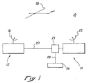
- Figure 1 shows a schematic view of a radar tracking system with a first radar system and a second radar system;
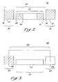
- Figure 2 graphically shows the time constraints on pulse repetition frequencies that permit a zero eclipsing pulse repetition frequency;
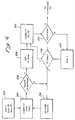
- Figure 3 graphically shows the Doppler frequency constraints on pulse repetition frequencies that permit a clear Doppler frequency pulse repetition frequency;
- Figure 4 shows a flow diagram of the steps and decisions to determine a zero eclipsing pulse repetition frequency; and
- Figure 5 shows a flow diagram of the steps and decisions to determine a clear Doppler frequency pulse repetition frequency.
-
- Referring to the figures, and specifically to Figure 1, a
radar tracking system 10 comprises afirst radar system 12 and asecond radar system 14. Thefirst radar system 12 has anantenna 16. Thefirst radar system 12 tracks atarget 18, estimates its range, and sends asignal 20 representing the target range estimate to thesecond radar system 14. Other embodiments of the invention may send additional target data signals (e.g., target velocity, acceleration, other characteristics) from thefirst radar system 12 to thesecond radar system 14. - The
second radar system 14 comprises anantenna 22, aCPU 24, and amanual input device 26. TheCPU 24 receives the targetrange estimate signal 20 through a signal input device (not shown). TheCPU 24 also receives manually inputteddata 28 through themanual input device 26. - The
CPU 24 processes the target range estimate to determine a usable pulse repetition frequency ("PRF") for thesecond radar 14. Embodiments of the invention may use a zero eclipsing algorithm to determine a set of PRFs that permits an interval "n" to be a zero eclipse interval. A zero eclipse interval does not have the transmitter pulse occurring during the reception of the target signal. Embodiments of the invention may use a clear Doppler frequency algorithm to determine a set of PRFs that permits an interval "m" to be a clear Doppler frequency interval. A clear Doppler frequency has a clear Doppler region that is free of clutter bandwidth. In a preferred embodiment of the invention, theCPU 24 uses an combination of the zero eclipsing algorithm and the clear Doppler frequency algorithm. - A set of zero eclipsing PRF intervals can be determined over a range of intervals given the estimated target range, Rcue, desired duty factor, df, and half of the range uncertainty swath, dR. Referring now to Figure 2, a
visual representation 50 of the time constraints in identifying a zero eclipsing PRF interval is shown.Signal 52 is the transmitted pulse at n andSignal 54 is the transmitted pulse at n+1. Thebeginnings signals interpulse period Rprf 60 of the PRF. Thewidth 62 of the transmitted pulses is the df times theRprf 60. An intervening receiver-ontime 64 is between thepulses time 64. Abeginning 68 of the receiver-ontime 64 is represented by equation (1) and the ending 70 of the receiver-ontime 64 is represented by equation (2): - The zero eclipsing algorithm comprises equations which are solved to determine zero eclipsing intervals "n". Based on the time constraints of the algorithm, the inequalities (3) and (4) are true:
- n = zero eclipse interval;
- df = desired duty factor;
- Rcue = estimate of target range; and
- dR = half of the range uncertainty swath. As the relation between Rprf and PRF is expressed by equation (5):
- Frh = highest zero eclipsing PRF for n;
- Frl = lowest zero eclipsing PRF for n;
- FrRANGE = range of zero eclipsing PRFs for n.
-
- The set of zero eclipsing intervals, n, consists of all intervals for which the equations (6)-(8) hold true. The zero eclipsing algorithm then either selects, or assisting in manually selecting, a usable RPF. In some embodiments of the invention, the instructions in the
CPU 24 choose a usable RPF from the FrRANGE having the lowest value of n. In a more preferred embodiment, the instructions in theCPU 24 chose the lowest available PRF as the usable PRF. Some embodiments of the invention have an algorithm that tests to ensure that the usable RPF is above a minimum RPF for thesecond radar system 14. Additional embodiments of the invention may solicit a manual choice of the usable RPF from a generated list of zero eclipsing PRFs, the manual choice being inputted through the manual input device 26 (Figure 1). - In another embodiment of the invention, the clear Doppler frequency algorithm determines a set of PRFs that permit a clear Doppler frequency interval "m" given the estimated target range, Rcue, desired duty factor, df, the Doppler uncertainty swath, ΔF, the center of a clear Doppler frequency region, fc, and the clutter bandwidth, Bwc. Now referring to Figure 3, a
visual representation 100 of the frequency constraints on the clear Doppler frequency region interval is shown. APRF 102 has Bwc's 104 centered on the PRF'sbeginning end 106 and terminatingend 108. Between the Bwc's 104 is aclear Doppler region 110, or the Doppler uncertainty swath, ΔF. At the middle 112 of theregion 110 is the center of the clear Doppler frequency region, fc. - The clear Doppler frequency algorithm is also representable through equations (9)-(11):
- m = clear Doppler frequency region interval;
- Ffh = highest Doppler frequency pulse repetition frequency for m;
- Ffl = lowest Doppler frequency pulse repetition frequency for m;
- fc = center of a clear Doppler frequency region;
- ΔF = Doppler uncertainty swath;
- Bwc = clutter bandwidth; and
- FfRANGE = range of Doppler frequency pulse repetition frequencies for m;
-
- The set of clear Doppler frequency region intervals, m, consists of all the intervals for which the equations (9)-(11) hold true. The clear Doppler frequency algorithm then selects a usable RPF from the set of FfRANGEs. In some embodiments of the invention, the instructions in the
CPU 24 choose a usable RPF from the FfRANGE having the lowest m. In a more preferred embodiment, the algorithm chooses the lowest PRF in the FfRANGE having the lowest m as the usable RPF. Some embodiments of the invention have an algorithm that tests to ensure that the usable RPF is above a minimum RPF for thesecond radar system 14. Additional embodiments of the invention may solicit a manual choice of the usable RPF from a generated list of clear Doppler frequency RPFs, the manual choice being inputted through the manual input device 26 (Figure 1). - In an embodiment of the invention, the usable PRF is chosen from the intersection of an FrRANGE and an FfRANGE. In a preferred embodiment of the invention, the usable PRF is chosen from the lowest n FrRANGE that has a matching PRF in any FfRANGE wherein the FfRANGE with matching PRF's are referred to as FfRANGE matching ranges. In a more preferred embodiment of the invention, the usable PRF is chosen from the lowest n FrRANGE and the FfRANGE matching range with the lowest m. In another embodiment of the invention, the usable PRF is chosen from the lowest m FfRANGE that has a matching PRF in any FrRANGE, wherein the FrRANGEs with matching PRF's are referred to as FrRANGE matching ranges. In a more preferred embodiment of the invention, the usable PRF is chosen from the lowest m FfRANGE and the FrRANGE matching range with the lowest n.
- In a preferred embodiment of the invention, the
CPU 24 of the second radar system 14 (see Figure 1) is instructed to choose a usable PRF via a set instructions. Figure 4 shows a flow chart 200 that is an example of a set of instructions for choosing a usable PRF that is zero eclipsing. Figure 5 shows aflow chart 220 that is an example of a set of instructions for choosing a usable PRF that has a clear Doppler frequency region. The flow charts are linked so that the usable PRF is a member of the lowest zero eclipse interval and a member of the lowest matching clear Doppler frequency region. From the flow chart 200, it is commonly known in the art how to translate the set of instructions into any usable computer language, how to "hard wire" the instructions, or a combination thereof into theCPU 24. - Referring now to Figure 4, flow chart 200 starts with a
step 202 of inputting target data comprising Rcue, Rdotcue, dR, and dF. Rdotcue is the velocity of the target. The target data is received from the first radar system and/or is inputted manually. Next, step 204 computes nmin and nmax using equations (12) and (13): - Fmin Δ minumum PRF (determined by hardware paramenters, such as IF bandwidth, or inputred by an operator)
- Trc Δ 2Rcue/c (the cued ranged to the target in seconds)
- Tdr = 2dR/c Δ (the size of the range uncertainity swath of the target in seconds) Next, in
-
- Now referring to
flow chart 220, in step 202 mmax and Ffl(mmax) is computed using equations (14) and (15): - fc = center of a clear Doppler frequency region;
- Bwc Δ bandwidth of main lobe clutter Next, in
- Fh = minimum of (Ffh, Frh); and
- Fl = maximum of (Ffl, Frl).
-
- Although presently preferred embodiments of the present invention have been described in detail hereinabove, it should be clearly understood that many variations and/or modifications of the basic inventive concepts herein taught, which may appear to those skilled in the pertinent art, will still fall within the spirit and scope of the present invention, as defined in the appended claims.
a set of zero eclipsing PRFs is represented by the equations (6) - (8)
Claims (11)
- A process for radar tracking of a target comprising the steps of:a. retrieving an estimate of a target range and a range uncertainty swatch from a first radar system;b. inputting the estimate of the target range, the range uncertainty swatch, and a duty factor into a second radar system;c. instructing the second radar system to determine a set of zero eclipse intervals, and respective ranges of range pulse repetition frequencies, that solves equations (1)-(3) :n = zero eclipse interval;Frh = highest range pulse repetition frequency for n;Frl = lowest range pulse repetition frequency for n;c = speed of light;df = desired duty factorRcue = estimate of target range;dR = half of the range uncertainty swatch; andFrRANGE = range of range pulse repetition frequencies for n;d. choosing a usable range pulse repetition frequency from the ranges of range pulse repetition frequencies from the set of zero eclipse intervals; ande. instructing the second radar system to track the target using the usable range pulse repetition frequency.
- The process of claim 1, wherein the usable range pulse repetition frequency is a member of a range of range pulse repetition frequencies for the lowest zero eclipse interval.
- The process of claim 1 or 2, further comprising the steps of:a. estimating a target Doppler frequency region and a Doppler uncertainty swatch;b. inputting the center of the clear Doppler frequency region and the Doppler uncertainty swatch into the second radar system;c. instructing the second radar system to determine a set of clear Doppler frequency region intervals, and respective ranges of Doppler frequency pulse repetition frequencies, that solves equations (4) - (6):m = clear Doppler frequency region interval;Ffh = highest Doppler frequency pulse repetition frequency for m;Ffl = lowest Doppler frequency pulse repetition frequency for m;fc = center of a clear Doppler frequency region;ΔF = Doppler uncertainty swatch;Bwc = clutter bandwidth; andFfRANGE = range of Doppler frequency pulse repetition frequencies for m;d. choosing a usable pulse repetition frequency that is present in at least one of the ranges of range pulse repetition frequencies and that is present in at least one of the ranges of Doppler frequency pulse repetition frequencies; ande. instructing the second radar system to track the target using the usable pulse repetition frequency.
- The process of claim 3, wherein the choosing step further comprises the steps of:a. identifying a lowest zero eclipse interval range of range pulse repetition frequencies that has one or more matching pulse repetition frequencies in one or more of the ranges of Doppler frequency pulse repetition frequencies, wherein the ranges of Doppler frequency pulse repetition frequencies with one or more matching pulse repetition frequencies define matching ranges; andb. choosing one of the matching pulse repetition frequencies as the usable pulse repetition frequency.
- The process of claims 3 or 4, wherein the choosing step further comprises the steps of:a. identifying a lowest clear Doppler frequency region interval range of Doppler frequency pulse frequencies for that has one or more matching pulse repetition frequencies in one or more of the ranges of range pulse repetition frequencies, wherein the range of range pulse repetition frequencies with one or more matching pulse repetition frequencies define matching ranges; andb. choosing one of the matching pulse repetition frequencies as the usable pulse repetition frequency.
- The process of claim 5, wherein the choosing step further comprises the step of choosing the matching pulse repetition frequency from the matching range having the lowest zero eclipse interval.
- A process for radar tracking of a target comprising the steps of:a. retrieving an estimate of a target range, a center of a clear Doppler frequency region, and a Doppler uncertainty swatch from a first radar system;b. inputting the center of the clear Doppler frequency region and the Doppler uncertainty swatch into a second radar system;c. instructing the second radar system to determine a set of clear Doppler frequency region intervals, and respective ranges of Doppler frequency pulse repetition frequencies, that solves equations (4) - (6) :m = clear Doppler frequency region interval;Ffh = highest Doppler frequency pulse repetition frequency for m;Ffl = lowest Doppler frequency pulse repetition frequency for m;fc = center of a clear Doppler frequency region;ΔF = Doppler uncertainty swatch;Bwc = clutter bandwidth; andFfRANGE = range of Doppler frequency pulse repetition frequencies for m;d. choosing a usable Doppler frequency pulse repetition frequency from the ranges of Doppler frequency pulse repetition frequencies from the set of clear Doppler frequency region intervals; ande. instructing the second radar system to track the target using the usable Doppler frequency pulse repetition frequency.
- The process of any of the claims 4-7, wherein the usable Doppler frequency pulse repetition frequency is a member of the lowest clear Doppler frequency region interval range of Doppler frequency pulse repetition frequencies.
- The process of any of the claims 1-8, wherein said second radar system is a missile guidance system.
- A radar tracking system for tracking a target in a target range comprising:a. a first radar system comprising means for making a target range estimate and sending a signal representing the target range estimate; andb. a second radar system comprising:i. a central processing unit comprising a signal input device for receiving target data comprising the target range estimate signal, a range of uncertainty swatch, and a duty factor;ii. zero eclipse code for determining from the target data a set of zero eclipse intervals, and respective ranges of range pulse repetition frequencies, by solving equations (1)-(3) :n = zero eclipse interval;Frh = highest range pulse repetition frequency for n;Frl = lowest range pulse repetition frequency for n;c = speed of light;df = desired duty factorRcue = estimate of target range;dR = half of the range uncertainty swatch; andFrRANGE = range of range pulse repetition frequencies for n;iii. first means for choosing a usable range pulse repetition frequency from the ranges of range pulse repetition frequencies from the set of zero eclipse intervals; andiv. means for instructing the second radar system to track the target using the usable range pulse repetition frequency.
- The system of claim 10, including means for implementing the process steps of any of claims 1-9.
Applications Claiming Priority (2)
| Application Number | Priority Date | Filing Date | Title |
|---|---|---|---|
| US96850 | 1998-06-11 | ||
| US09/096,850 US6064331A (en) | 1998-06-11 | 1998-06-11 | Pulse repetition frequency section method and system |
Publications (2)
| Publication Number | Publication Date |
|---|---|
| EP0964267A2 true EP0964267A2 (en) | 1999-12-15 |
| EP0964267A3 EP0964267A3 (en) | 2000-07-19 |
Family
ID=22259390
Family Applications (1)
| Application Number | Title | Priority Date | Filing Date |
|---|---|---|---|
| EP99201848A Withdrawn EP0964267A3 (en) | 1998-06-11 | 1999-06-10 | Pulse repetition frequency selection method and system |
Country Status (2)
| Country | Link |
|---|---|
| US (1) | US6064331A (en) |
| EP (1) | EP0964267A3 (en) |
Cited By (1)
| Publication number | Priority date | Publication date | Assignee | Title |
|---|---|---|---|---|
| EP2472285A1 (en) * | 2010-12-30 | 2012-07-04 | Thales | Method for improving the performance of a radar in the presence of broadcast backscattered echoes |
Families Citing this family (10)
| Publication number | Priority date | Publication date | Assignee | Title |
|---|---|---|---|---|
| SE522651C2 (en) * | 2002-06-14 | 2004-02-24 | Totalfoersvarets Forskningsins | Methods and systems for determining the locations of the targets through bistatic measurements with signals spread from the target |
| US6621450B1 (en) | 2002-07-12 | 2003-09-16 | Lockheed Martin Corporation | Method of selecting a pulse repetition frequency to detect, track or search for a target |
| JP5635723B2 (en) * | 2006-01-30 | 2014-12-03 | 富士通株式会社 | Target detection apparatus and system |
| US8077074B2 (en) * | 2008-05-07 | 2011-12-13 | Colorado State University Research Foundation | Networked waveform system |
| JP4766404B2 (en) * | 2008-10-28 | 2011-09-07 | トヨタ自動車株式会社 | Radar equipment |
| KR101072485B1 (en) * | 2011-06-24 | 2011-10-11 | 한국해양연구원 | Apparatus for 3-d radar implementation using vessel radar |
| JP6278949B2 (en) * | 2013-03-18 | 2018-02-14 | パナソニック株式会社 | Radar equipment |
| CN106443662B (en) * | 2016-10-28 | 2018-12-11 | 上海无线电设备研究所 | A kind of target steady correlating method under low repetition system when velocity ambiguity |
| US9736845B1 (en) * | 2017-01-03 | 2017-08-15 | Network Performance Research Group Llc | Over the air signaling of dynamic frequency selection (DFS) operating parameters to client devices |
| RU2666783C1 (en) * | 2017-09-06 | 2018-09-12 | Акционерное общество "Федеральный научно-производственный центр "Нижегородский научно-исследовательский институт радиотехники" | Method and device for protection from “angels” in complexation of radar stations of different ranges |
Citations (3)
| Publication number | Priority date | Publication date | Assignee | Title |
|---|---|---|---|---|
| US4593286A (en) * | 1983-04-25 | 1986-06-03 | Westinghouse Electric Corp. | Method of operating an agile beam coherent radar |
| FR2599853A1 (en) * | 1981-05-15 | 1987-12-11 | Thomson Csf | METHOD FOR REMOTE AMBIGUE RISE IN PULSE RADAR DOPPLER, DEVICE FOR ITS IMPLEMENTATION AND RADAR COMPRISING SUCH A DEVICE |
| US5430445A (en) * | 1992-12-31 | 1995-07-04 | Raytheon Company | Synthetic aperture radar guidance system and method of operating same |
Family Cites Families (10)
| Publication number | Priority date | Publication date | Assignee | Title |
|---|---|---|---|---|
| US2703399A (en) * | 1946-02-15 | 1955-03-01 | Everard M Williams | Apparatus for guiding and detonating missiles |
| US4143373A (en) * | 1977-09-21 | 1979-03-06 | Hughes Aircraft Company | Adaptive radar systems and methods therefor |
| US5185608A (en) * | 1980-12-29 | 1993-02-09 | Raytheon Company | All weather tactical strike system (AWISS) and method of operation |
| US5061934A (en) * | 1990-11-09 | 1991-10-29 | The United States Of America As Represented By The Secretary Of The Air Force | Hybrid clutter cancellation method and system for improved radar performance |
| US5173706A (en) * | 1991-04-16 | 1992-12-22 | General Electric Company | Radar processor with range sidelobe reduction following doppler filtering |
| DE4131141A1 (en) * | 1991-09-19 | 1993-03-25 | Telefunken Systemtechnik | METHOD FOR DISTINATING AT LEAST TWO GOALS |
| US5546084A (en) * | 1992-07-17 | 1996-08-13 | Trw Inc. | Synthetic aperture radar clutter reduction system |
| US5294933A (en) * | 1993-01-29 | 1994-03-15 | Westinghouse Electric Corp. | Wideband radar system utilizing adaptive interference canceler |
| US5440311A (en) * | 1993-08-06 | 1995-08-08 | Martin Marietta Corporation | Complementary-sequence pulse radar with matched filtering and Doppler tolerant sidelobe suppression preceding Doppler filtering |
| US5486830A (en) * | 1994-04-06 | 1996-01-23 | The United States Of America As Represented By The United States Department Of Energy | Radar transponder apparatus and signal processing technique |
-
1998
- 1998-06-11 US US09/096,850 patent/US6064331A/en not_active Expired - Fee Related
-
1999
- 1999-06-10 EP EP99201848A patent/EP0964267A3/en not_active Withdrawn
Patent Citations (3)
| Publication number | Priority date | Publication date | Assignee | Title |
|---|---|---|---|---|
| FR2599853A1 (en) * | 1981-05-15 | 1987-12-11 | Thomson Csf | METHOD FOR REMOTE AMBIGUE RISE IN PULSE RADAR DOPPLER, DEVICE FOR ITS IMPLEMENTATION AND RADAR COMPRISING SUCH A DEVICE |
| US4593286A (en) * | 1983-04-25 | 1986-06-03 | Westinghouse Electric Corp. | Method of operating an agile beam coherent radar |
| US5430445A (en) * | 1992-12-31 | 1995-07-04 | Raytheon Company | Synthetic aperture radar guidance system and method of operating same |
Cited By (2)
| Publication number | Priority date | Publication date | Assignee | Title |
|---|---|---|---|---|
| EP2472285A1 (en) * | 2010-12-30 | 2012-07-04 | Thales | Method for improving the performance of a radar in the presence of broadcast backscattered echoes |
| FR2970084A1 (en) * | 2010-12-30 | 2012-07-06 | Thales Sa | METHOD FOR IMPROVING THE PERFORMANCE OF A RADAR IN THE PRESENCE OF DIFFUSED RETROFLECTING ECHOS |
Also Published As
| Publication number | Publication date |
|---|---|
| US6064331A (en) | 2000-05-16 |
| EP0964267A3 (en) | 2000-07-19 |
Similar Documents
| Publication | Publication Date | Title |
|---|---|---|
| CN110161504B (en) | Vehicle radar system for solving Doppler shift and using method thereof | |
| EP1681583B1 (en) | Vehicle radar process | |
| EP0557945B1 (en) | Ranging, detection and resolving in a multislope frequency modulated waveform radar system | |
| US5923282A (en) | Radar system | |
| US5784026A (en) | Radar detection of accelerating airborne targets | |
| US5977905A (en) | Target detection method and device for wideband unambiguous pulse Doppler radar | |
| AU2004282851B2 (en) | Efficient technique for estimating elevation angle when using a broad beam for search in a radar | |
| EP0964267A2 (en) | Pulse repetition frequency selection method and system | |
| US20070241955A1 (en) | System Having Two or More Sensors | |
| US5990824A (en) | Ground based pulse radar system and method providing high clutter rejection and reliable moving target indication with extended range for airport traffic control and other applications | |
| US6184820B1 (en) | Coherent pulse radar system | |
| JPH05249234A (en) | Method for identifying at least two targets | |
| JP2002520624A (en) | Non-coherent gain enhancement techniques for improved detection evaluation performance | |
| JPWO2006013614A1 (en) | Radar equipment | |
| CN110431436A (en) | For seeking the method and radar equipment of the diametrically acceleration of at least one target | |
| EP0126032B1 (en) | Device for the identification and suppression of unwanted second trace echoes in radar systems | |
| US5745071A (en) | Method and apparatus for precisely locating a resonant object | |
| WO2003096067A1 (en) | Methods and apparatus for accurate phase detection | |
| US7339519B2 (en) | Methods and apparatus for target radial extent determination using deconvolution | |
| JP2007500856A (en) | Method and apparatus for weighting radar return data | |
| JPH05223931A (en) | Mode s type interrogator with improved performance | |
| US20030222808A1 (en) | Radar imaging system and method | |
| DE69935483T2 (en) | PROCESSING METHOD WITH A SPECIFIC WAVEFORM FOR A UNSYNCHRONIZED KOHERENT, BROADBAND BISTATIC RADAR OPERATION | |
| JPS61140881A (en) | Pulse-radar device | |
| JPH06214023A (en) | Radar apparatus provided with composed diaphragm based on rotary antenna |
Legal Events
| Date | Code | Title | Description |
|---|---|---|---|
| PUAI | Public reference made under article 153(3) epc to a published international application that has entered the european phase |
Free format text: ORIGINAL CODE: 0009012 |
|
| AK | Designated contracting states |
Kind code of ref document: A2 Designated state(s): DE FR GB |
|
| AX | Request for extension of the european patent |
Free format text: AL;LT;LV;MK;RO;SI |
|
| PUAL | Search report despatched |
Free format text: ORIGINAL CODE: 0009013 |
|
| AK | Designated contracting states |
Kind code of ref document: A3 Designated state(s): AT BE CH CY DE DK ES FI FR GB GR IE IT LI LU MC NL PT SE |
|
| AX | Request for extension of the european patent |
Free format text: AL;LT;LV;MK;RO;SI |
|
| 17P | Request for examination filed |
Effective date: 20001227 |
|
| AKX | Designation fees paid |
Free format text: DE FR GB |
|
| STAA | Information on the status of an ep patent application or granted ep patent |
Free format text: STATUS: THE APPLICATION IS DEEMED TO BE WITHDRAWN |
|
| 18D | Application deemed to be withdrawn |
Effective date: 20050104 |