EP0964244B1 - Multi-channel integrating sphere - Google Patents
Multi-channel integrating sphere Download PDFInfo
- Publication number
- EP0964244B1 EP0964244B1 EP99304615A EP99304615A EP0964244B1 EP 0964244 B1 EP0964244 B1 EP 0964244B1 EP 99304615 A EP99304615 A EP 99304615A EP 99304615 A EP99304615 A EP 99304615A EP 0964244 B1 EP0964244 B1 EP 0964244B1
- Authority
- EP
- European Patent Office
- Prior art keywords
- sample
- receiver
- port
- viewing
- integrating sphere
- Prior art date
- Legal status (The legal status is an assumption and is not a legal conclusion. Google has not performed a legal analysis and makes no representation as to the accuracy of the status listed.)
- Expired - Lifetime
Links
- 230000003287 optical effect Effects 0.000 claims description 38
- 230000005855 radiation Effects 0.000 claims description 23
- 238000005259 measurement Methods 0.000 description 31
- 230000008901 benefit Effects 0.000 description 9
- 238000004737 colorimetric analysis Methods 0.000 description 7
- 238000005286 illumination Methods 0.000 description 7
- 238000006073 displacement reaction Methods 0.000 description 6
- 239000000835 fiber Substances 0.000 description 6
- 238000012360 testing method Methods 0.000 description 6
- 238000013461 design Methods 0.000 description 5
- 230000007717 exclusion Effects 0.000 description 5
- 238000001514 detection method Methods 0.000 description 4
- 230000004907 flux Effects 0.000 description 3
- 230000003595 spectral effect Effects 0.000 description 3
- NKNQXCZWYOZFLT-XAVROVCUSA-N (4s)-4-[4-[(2r)-1-amino-2-methylbutyl]triazol-1-yl]-5-[4-[4-[4-[(2s)-2-[4-[(2r)-1-amino-2-methylbutyl]triazol-1-yl]-4-carboxybutanoyl]piperazin-1-yl]-6-[2-[2-(2-prop-2-ynoxyethoxy)ethoxy]ethylamino]-1,3,5-triazin-2-yl]piperazin-1-yl]-5-oxopentanoic acid;h Chemical compound Cl.N1=NC(C(N)[C@H](C)CC)=CN1[C@@H](CCC(O)=O)C(=O)N1CCN(C=2N=C(N=C(NCCOCCOCCOCC#C)N=2)N2CCN(CC2)C(=O)[C@H](CCC(O)=O)N2N=NC(=C2)C(N)[C@H](C)CC)CC1 NKNQXCZWYOZFLT-XAVROVCUSA-N 0.000 description 2
- 230000008859 change Effects 0.000 description 2
- 230000001419 dependent effect Effects 0.000 description 2
- 238000012986 modification Methods 0.000 description 2
- 230000004048 modification Effects 0.000 description 2
- 239000013307 optical fiber Substances 0.000 description 2
- 238000005070 sampling Methods 0.000 description 2
- 238000001228 spectrum Methods 0.000 description 2
- 230000006978 adaptation Effects 0.000 description 1
- 230000004075 alteration Effects 0.000 description 1
- 238000004458 analytical method Methods 0.000 description 1
- 238000010276 construction Methods 0.000 description 1
- 238000012937 correction Methods 0.000 description 1
- 238000011161 development Methods 0.000 description 1
- 230000003467 diminishing effect Effects 0.000 description 1
- 230000009977 dual effect Effects 0.000 description 1
- 230000000694 effects Effects 0.000 description 1
- 238000004049 embossing Methods 0.000 description 1
- 238000005516 engineering process Methods 0.000 description 1
- 239000004744 fabric Substances 0.000 description 1
- 239000000463 material Substances 0.000 description 1
- 230000007246 mechanism Effects 0.000 description 1
- 238000000034 method Methods 0.000 description 1
- 238000012545 processing Methods 0.000 description 1
- 230000009467 reduction Effects 0.000 description 1
- 238000002310 reflectometry Methods 0.000 description 1
- 229910052724 xenon Inorganic materials 0.000 description 1
- FHNFHKCVQCLJFQ-UHFFFAOYSA-N xenon atom Chemical compound [Xe] FHNFHKCVQCLJFQ-UHFFFAOYSA-N 0.000 description 1
Images


Classifications
-
- G—PHYSICS
- G01—MEASURING; TESTING
- G01N—INVESTIGATING OR ANALYSING MATERIALS BY DETERMINING THEIR CHEMICAL OR PHYSICAL PROPERTIES
- G01N21/00—Investigating or analysing materials by the use of optical means, i.e. using sub-millimetre waves, infrared, visible or ultraviolet light
- G01N21/17—Systems in which incident light is modified in accordance with the properties of the material investigated
- G01N21/47—Scattering, i.e. diffuse reflection
- G01N21/4738—Diffuse reflection, e.g. also for testing fluids, fibrous materials
- G01N21/474—Details of optical heads therefor, e.g. using optical fibres
-
- G—PHYSICS
- G01—MEASURING; TESTING
- G01J—MEASUREMENT OF INTENSITY, VELOCITY, SPECTRAL CONTENT, POLARISATION, PHASE OR PULSE CHARACTERISTICS OF INFRARED, VISIBLE OR ULTRAVIOLET LIGHT; COLORIMETRY; RADIATION PYROMETRY
- G01J3/00—Spectrometry; Spectrophotometry; Monochromators; Measuring colours
- G01J3/02—Details
- G01J3/0205—Optical elements not provided otherwise, e.g. optical manifolds, diffusers, windows
- G01J3/0251—Colorimeters making use of an integrating sphere
-
- G—PHYSICS
- G01—MEASURING; TESTING
- G01J—MEASUREMENT OF INTENSITY, VELOCITY, SPECTRAL CONTENT, POLARISATION, PHASE OR PULSE CHARACTERISTICS OF INFRARED, VISIBLE OR ULTRAVIOLET LIGHT; COLORIMETRY; RADIATION PYROMETRY
- G01J3/00—Spectrometry; Spectrophotometry; Monochromators; Measuring colours
- G01J3/02—Details
- G01J3/0205—Optical elements not provided otherwise, e.g. optical manifolds, diffusers, windows
- G01J3/0254—Spectrometers, other than colorimeters, making use of an integrating sphere
-
- G—PHYSICS
- G01—MEASURING; TESTING
- G01J—MEASUREMENT OF INTENSITY, VELOCITY, SPECTRAL CONTENT, POLARISATION, PHASE OR PULSE CHARACTERISTICS OF INFRARED, VISIBLE OR ULTRAVIOLET LIGHT; COLORIMETRY; RADIATION PYROMETRY
- G01J3/00—Spectrometry; Spectrophotometry; Monochromators; Measuring colours
- G01J3/02—Details
- G01J3/0294—Multi-channel spectroscopy
-
- G—PHYSICS
- G01—MEASURING; TESTING
- G01N—INVESTIGATING OR ANALYSING MATERIALS BY DETERMINING THEIR CHEMICAL OR PHYSICAL PROPERTIES
- G01N21/00—Investigating or analysing materials by the use of optical means, i.e. using sub-millimetre waves, infrared, visible or ultraviolet light
- G01N21/17—Systems in which incident light is modified in accordance with the properties of the material investigated
- G01N21/55—Specular reflectivity
- G01N2021/555—Measuring total reflection power, i.e. scattering and specular
-
- G—PHYSICS
- G01—MEASURING; TESTING
- G01N—INVESTIGATING OR ANALYSING MATERIALS BY DETERMINING THEIR CHEMICAL OR PHYSICAL PROPERTIES
- G01N21/00—Investigating or analysing materials by the use of optical means, i.e. using sub-millimetre waves, infrared, visible or ultraviolet light
- G01N21/17—Systems in which incident light is modified in accordance with the properties of the material investigated
- G01N21/55—Specular reflectivity
- G01N2021/556—Measuring separately scattering and specular
-
- G—PHYSICS
- G01—MEASURING; TESTING
- G01N—INVESTIGATING OR ANALYSING MATERIALS BY DETERMINING THEIR CHEMICAL OR PHYSICAL PROPERTIES
- G01N21/00—Investigating or analysing materials by the use of optical means, i.e. using sub-millimetre waves, infrared, visible or ultraviolet light
- G01N21/17—Systems in which incident light is modified in accordance with the properties of the material investigated
- G01N21/25—Colour; Spectral properties, i.e. comparison of effect of material on the light at two or more different wavelengths or wavelength bands
- G01N21/251—Colorimeters; Construction thereof
Definitions
- This invention relates generally to integrating spheres and, more particularly, to an integrating sphere with multiple ports for concurrently receiving light directly reflected from a sample under test.
- integrating spheres for the optical measurement geometry in reflectance colorimetry is a standard practice, and is described in the Commission Internationale De L'Eclairage (CIE) Publication Number 15.2 (Colorimetry), 1986.
- CIE Commission Internationale De L'Eclairage
- An integrating sphere is an apparatus with an interior cavity (typically spherical) having a highly reflective, optically diffuse white surface.
- the simplest integrating sphere design contains two apertures, one which admits light and another which serves as a measurement port where the amount of light on the surface of the sphere can be measured.
- An integrating sphere has the property that at any point on the inner surface of the sphere the illumination is essentially independent of the direction and location of the incident beam as well as the size of the beam; the inner surface is uniformly illuminated throughout, except at the point of direct illumination. Integrating spheres are used in colorimetry for the precise determination of color for a sample under test.
- a common practice in colorimetry is to measure a sample with the specular component of reflection (mirror-like reflection from the surface) either included (SCI mode) or excluded (SCE mode). Other aspects of measurement may include selection of the size of the measured sample surface, spectral content of the illumination, and angle of receiver beam with respect to the sample normal. Instruments designed for colorimetry traditionally measure the sample one configuration at a time (e.g. SCI or SCE mode with a single size of measured area), usually requiring a change of configuration or another instrument to select another mode combination. For example, most integrating-sphere colorimeters are capable of measuring the sample with the specular component either included or excluded.
- Changing between SCI and SCE modes is usually achieved by the use of a movable segment of the integrating sphere which removes the specular component for SCE measurements or includes the specular component for SCI measurements.
- the included/excluded option requires separate measurements with a time between to move the segment and mechanical means to do so.
- the '481 patent constrains the simultaneous SCE and SCI paths (presumably measuring the same sample area-of-view size) to being "opposite" each other relative to the sample axis normal, and describes only this arrangement of an SCI and SCE port, the number of measurement paths limited to just these two plus the conventional reference path.
- Other instruments are equipped with multiple measuring "paths" which measure the color of the sample in one measurement path and measure a different parameter of the sample's appearance, such as gloss, with a second measurement system.
- An example includes the Color and Appearance Technology, Inc. SPECTRO/plus TM Spectrophotometer.
- the instrument provides a separate measurement system for the gloss; this separate measurement path does not measure the "color” of the sample and has a unique geometry specific to gloss measurement standards, such as ASTM D523, published by the American Society for Testing and Materials (ASTM) of Philadelphia, PA. Therefore, the SPECTRO/plus TM only has one color measurement path.
- DE-A-44 23 698 discloses an integrating sphere comprising ports, sensors, one or more light sources for an diffusely illuminating, using inner wall parts, a sample, a sample port, apertures or lenses, for measuring the directed and diffuse degree of a reflection, wherein the inner wall of the sphere is white coated.
- the one ore more light sources are arranged such that no light beam is directly directed to the sample and/or to the sensors.
- the inner wall parts are regions of the inner wall of the sphere which have different luminance, preferably black and white.
- the sensor is constraint by apertures or lenses such that the sensor only receives the black port via the sample.
- the port and the corresponding inner wall are in coincidence.
- the optical apertures and/or lenses are arranged, such that they only can receive the sample port which is covered by the sample.
- the present invention overcomes the above, and other, limitations of the prior art and the background art by providing an integrating sphere according to claim 1.
- the first and second lines preferably intersect the sample surface at a common point.
- first and second angles are equal.
- the present invention provides an integrating sphere which features the capability of multiple measurement modes (e.g., multiple SCE, SCE and SCI, multiple SCI), multiple areas-of-view for a given measurement mode, multiple viewing angles per measurement mode, and combinations thereof, as will be more fully appreciated hereinbelow.
- multiple measurement modes e.g., multiple SCE, SCE and SCI, multiple SCI
- multiple areas-of-view for a given measurement mode e.g., multiple SCE, SCE and SCI, multiple SCI
- multiple viewing angles per measurement mode e.g., multiple viewing angles per measurement mode, and combinations thereof, as will be more fully appreciated hereinbelow.
- the term integrating sphere is not intended to limit the interior cavity to a spherical shape, but is used, as understood by one of ordinary skill in the art, to refer to a class of instruments used for measuring light reflectance of a test sample; different shapes of the interior cavity may be implemented.
- a port generally refers to a region of the integrating sphere in which the highly reflective, optically diffuse inner surface is absent, and typically includes an aperture formed through the inner wall.
- a colorimeter integrating sphere includes a sample port and one or more viewing ports, and, as described hereinbelow, may also include a specular exclusion port (SEP) and/or a reference port.
- SEP specular exclusion port
- a viewing port has an associated receiver and is characterized by a viewing beam representing the ray bundle of optical radiation received by the associated receiver directly from optical radiation reflected by the sample.
- the areal cross section of the viewing beam of a receiver at the associated viewing port may be less than or equal to the overall cross-sectional area of the viewing port itself. Where the port area is greater than the receiver area, the region of the port surrounding the receiver portion typically has low reflectivity.
- a ray viewing angle refers to the angle between a ray of the viewing beam and the normal to the sample surface where the ray intersects the sample surface.
- a viewing beam plane refers to a plane defined by a ray in the viewing beam and the normal to the sample surface at the intersection of the sample surface and the ray.
- An azimuthal angle between two viewing beams is represented by the angle, in a plane perpendicular to a sample normal, between two viewing planes of the respective viewing beams.
- a viewing beam may include rays which deviate from each other (i.e., are not parallel) within some range (e.g., the incorporated CIE publication prescribes that the angle between the viewing beam axis and any ray of the viewing beam should not exceed 5°), thus resulting in a finite range of azimuthal angles of the viewing rays relative to a given plane, as well as a finite range of viewing angles for the viewing beam.
- a viewing beam is typically symmetric about a viewing axis (i.e., the central axial ray of the viewing beam), this viewing axis is typically used for describing the (effective) viewing angle for the viewing beam as well as the (effective) azimuthal angle relative to the viewing beam.
- a second port is sometimes said to be opposite relative to a first port (also referred to the first port having an opposing port) if a mirror image beam of the first port's viewing beam mirrored from the sample surface (i.e., each ray of the ray bundle specularly reflected by the sample surface) is substantially overlapped by (e.g., encompassed by) the second port such that the specular component of the first port is completely or effectively excluded.
- the second port encompasses substantially the entire region from which optical radiation specularly reflected from the sample surface into the viewing beam of the first port would originate if the second port were not there (i.e., if the region were diffusely scattering).
- the second port is located at the portion of the integrating sphere wall corresponding to substantially all specular (regular) components for the first port.
- two ports are said to be opposite each other if the first port is opposite the second port (as described) and the second port is also opposite the first port such that the mirror image beam of the second port's viewing beam mirrored from the sample surface is substantially overlapped by the first port.
- a port's receiver area may be smaller than the port's area, if two ports are opposite each other, it does not necessarily follow that the viewing beams view overlapping sample surface regions or that the viewing beams have equal viewing angles: the mirror image of each viewing beam may project into the extra-receiver region of the opposing port, and the extra-receiver region of the port(s) may be of sufficient area to allow for differences in viewing angles and/or viewed sample surface regions.
- adjacent, non-concentric (e.g., non-overlapping) sample surface regions may be viewed by ports which are opposite to each other and have the same viewing angle; or, a common, overlapping surface region may be viewed by ports which are opposite to each other and have slightly different viewing angles.
- a second port may be opposite relative to a first port but the first port may not be opposite to the second port: the viewing beam of the second port mirrored from the sample surface may not be substantially overlapped by the first port, whereas the viewing beam of the first port mirrored from the sample surface may be substantially overlapped by the second port.
- the first port and the second port i.e., their viewing planes
- the first port and the second port may be azimuthally displaced by about 180° but with unequal viewing angles such that the second port encompasses a region of the integrating sphere inner surface from where the regular component for the first port receiver would originate but the viewing angle of the second port is such that the first port is not located at the region from where the specular component for the first port arrives.
- the first and second ports may be azimuthally displaced by about 180° with equal viewing angles, but viewing non-concentric (e.g., non-overlapping) sample surface regions, such that the second port encompasses a region of the integrating sphere inner surface from where the regular component for the first port receiver would originate but the viewed sample region displacement is such that the first port is not located at the region from where the specular component for the first port arrives.
- two ports may have any respective combination of viewing angles (including equal viewing angles), and may be azimuthally displaced by any angle not equal to about 180° with the first port's projected beam substantially overlapped by the second port, the ports thus viewing non-concentric (e.g., non-overlapping) surface regions of the sample.
- a second port is said to be non-opposite to a first port if the first port's viewing beam mirrored from the sample surface (i.e., the projection of the first port's viewing beam) is not substantially overlapped by the second port, the first port viewing beam having a not insubstantial specular component.
- the ports i.e., their viewing planes
- the ports may be displaced by an azimuthal angle different from 180° and have any combination of viewing angles provided neither port's viewing beam projection is substantially overlapped by the other port.
- two non-oppositely disposed ports may nevertheless be azimuthally displaced by about 180° if, for example, they have sufficiently different viewing angles and/or they view sufficiently non-concentric (e.g., non-overlapping) sample regions, such that the projection of each beam is not substantially overlapped by the other port.
- spatial relationships between ports is a general one which depends on the relative orientations of the viewing beams with respect to the sample plane (e.g., their respective viewing angles and viewing regions, and their relative azimuthal displacement), and which does not depend on a specific integrating sphere geometry or on a predetermined relationship of the viewing beams to each other or to the integrating sphere geometry.
- each viewing port has a viewing beam that is directed towards the sample along a viewing axis about which the viewing beam is symmetric and which intersects the sample plane at a common point which is typically also the point of intersection of the sample plane by a normal thereto which is a central axis of the integrating sphere (assuming the integrating sphere has a spherical cavity, this central axis passes through the center of the spherical cavity and the center of the sample port).
- a viewing beam that is directed towards the sample along a viewing axis about which the viewing beam is symmetric and which intersects the sample plane at a common point which is typically also the point of intersection of the sample plane by a normal thereto which is a central axis of the integrating sphere (assuming the integrating sphere has a spherical cavity, this central axis passes through the center of the spherical cavity and the center of the sample port).
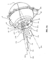
- FIGS. 1A-1E there is shown an integrating sphere 1 according to an embodiment of the present invention. More specifically: FIG. 1A depicts an isometric view, with certain features of the receivers exposed for clarity, of an integrating sphere according to an embodiment of the present invention; FIG. 1B depicts a plan (top) view, from the receiver side, of the integrating sphere, also with certain features of the receivers exposed for clarity; FIG. 1C is a cross-sectional view of the integrating sphere along line IC-IC of FIG. 1B; FIG. 1D is a cross-sectional view of the integrating sphere along line ID-ID of FIG. 1B; and FIG. 1E is a cross-sectional view of the integrating sphere along line IE-IE of FIG. 1D.
- Integrating sphere 1 includes two halves to facilitate construction: the two halves may be machined properly to fit one within the other, and appropriately secured with standard fastening mechanisms.
- Integrating sphere 1 includes a cavity having a highly reflective, optically diffuse surface 1a illuminated with a light source 2 (lamp) which may be coupled to the integrating sphere 1 in a conventional way using an entrance port 3 (aperture in the integrating sphere). Power to the lamp is supplied via lamp leads 32a, 32b, and 32c.
- the light source 2 may be a pulsed lamp of high intensity, short duration, and with a full "white" spectrum, such as a pulsed Xenon lamp. The effect is to diffusely illuminate sample 6 at port 7, in a conventional way.
- lamp 2 is external to the integrating sphere 1 cavity, housed in a lamp cavity 30 adjoined to integrating sphere 1 .
- Lamp 2 may alternatively be placed at least partially internal the cavity of integrating sphere 1, and may be placed substantially internal to the integrating sphere cavity to achieve the following advantages: optical flux efficiency, mechanical simplicity, small size, and reduction of port apertures which allows a smaller integrating sphere 1 to be used for a given sample port 7 size while conforming to standards for integrating sphere design.
- the lamp may be external to the sphere and projection optics (e.g., lens, etc.) may be used to relay or project flux from the lamp through the entrance port and to a spot at the far side of the integrating sphere interior.
- baffle 4a with highly reflective, optically diffuse surface is used in a conventional way to block light rays from directly illuminating the sample 6 (shown in FIGS. 1C and 1D, only) from the lamp, or from the entrance port 3 if used.
- baffle 4b prevents light rays originating at entrance port 3 or lamp 2 from directly illuminating portions of the sphere surface from where specular flux for the SCI receivers originates.
- diffusely illuminated sample 6 is viewed by multiple optical receivers 8a-d (i.e., four receivers in the present embodiment), each of which receives a portion of optical radiation reflected from sample 6 and provides it to a sensor or detector used to analyze the spectral content of the received optical radiation. More particularly, shown are multiple viewing ports including specular-component-excluded (SCE) port 11a, SCE port 11b, specular-component-included (SCI) port 11c, and SCI port 11d.
- SCE specular-component-excluded
- SCI specular-component-included
- Each port has an associated receiver comprising associated receiver optics (shown exposed) according to the present embodiment: SCE port 11a has a receiver 8a including aperture stop 22a, lens 24a, and fiber 17a; SCE port 11b has receiver 8b including aperture stop 22b, lens 24b, and fiber 17b; SCI port 11c has receiver 8c including aperture stop 22c, lens 24c, and fiber 17c; SCI port 11d has a receiver 8d including aperture stop 22d, lens 24d, and fiber 17d .
- Each receiver 8a-d is directed at sample port 7 along a corresponding one of viewing axes 26a, 26b, 26c, and 26d, which according to the present embodiment, converge to a common point of intersection at the surface of sample 6. It is understood that actual components of the receivers may differ, depending on design criteria, applications, preference, etc.
- the optical receivers 8a-d of the present embodiment are located at a same predetermined viewing angle from the sample normal (less than 10° to comply with standards for colorimetry, 8° in the present embodiment) and each has its own associated receiver viewing port 11a-d in the integrating sphere 1.
- the receivers For each viewing mode (i.e., SCE and SCI), the receivers have two subtense angles, corresponding to two sample area sizes.
- the optical receivers 8a-d and their respective receiver viewing ports 11a-d are displaced azimuthally, thereby advantageously maintaining the same predetermined viewing angle from the sample normal, and the azimuthal displacements are chosen to conveniently fit optical receivers 8a-d (and their associated viewing ports 11a-d), each designed with a combination of chosen parameters.
- the parameters include, but are not limited to, the measured size of the sample surface, the subtense angles of the receivers, and the inclusion (SCI) or exclusion (SCE) of the specular-reflected light. Additional and non-exclusive parameters (not used in the present embodiment) include multiple viewing angles, and different viewing regions of the sample surface (e.g., non-overlapping, non-concentric).
- Integrating sphere 1 includes one SCE mode receiver and one SCI mode receiver for each of two different measured areas-of-view (four receivers total).
- the two SCE receivers 8a and 8b having viewing axes 26a and 26b which intersect the sample at a common point, have equal viewing angles and are azimuthally displaced by 180°, and are thereby opposite each other.
- SCE ports 11a and 11b are sized appropriately to exclude substantially all specular rays for the respectively opposing associated SCE receivers 8b and 8a .
- SCI receivers 8c and 8d are placed out of the plane defined by the viewing beams of SCE receivers 8a and 8b, and also at the same predetermined viewing angle from the common sample normal located at the intersection of the sample by the viewing axes, such that the specular component is provided by the inclusion of the integrating sphere surface (no ports) at the regions intersected by the respectively projected SCI receiver viewing beams.
- each SCE port is designed to exclude substantially all specular components for the opposing SCE receiver.
- Such a shared arrangement of SCE/viewing ports advantageously reduces the total port area required to implement a plurality of SCE ports.
- integrating sphere 1 preferably includes an added receiver, having associated reference port 16, which provides a measurement of the illumination which is not a direct reflection from sample 6 and preferably not directly incident from lamp 2 or lamp port 3.
- the viewing beam received via reference port 16 is referred to as a reference beam, and can be used to correct or to control the lamp 2 fluctuations and to compensate for the influence of the sample 6 reflectance on the integrating sphere 1 illumination.
- reference port 16 location and its associated receiver characteristics are such that only light diffusely reflected from optically diffuse surface 1a of integrating sphere 1 is received.
- the reference beam is conveniently redirected by fold mirror 36 into an optical fiber (not shown) coupled to reference fiber mount 34. It is appreciated that for the current invention, this reference path is not considered or counted as one of the multiple measurement paths.
- the spectral content of the optical radiation collected (received) by each of the multiple receivers is analyzed by any of a variety of conventional means, such as filters or spectroscopic optics and appropriate signal processing (not illustrated).
- the optical radiation collected (received) concurrently (in parallel) by the multiple optical receivers 8a-d is detected (i.e., converted from an optical to an electrical signal) in parallel for each receiver, and further, is also detected in parallel spectrum-wise (i.e., for each receiver, the complete spectrum is detected in parallel).
- the optical radiation received by the multiple optical receivers 8a-d is detected substantially simultaneously.
- Analysis of the detected signals may be performed, for example, in order to condition the detected signal and calculate the sample's color using standard formulae, as in the incorporated CIE reference.
- receiving optical radiation is distinguished from detecting optical radiation: the former is used to refer to optical radiation scattered/reflected from the sample surface being coupled into (accepted by) a receiver, whereas the latter is used to refer to received optical radiation being sensed (e.g., converted to an electrical signal) by a detector.
- receivers are said to concurrently receive optical radiation when optical radiation scattered/reflected from the sample impinges on the receivers in parallel; this concurrent reception does not mean that the concurrently received optical radiation is necessarily also detected concurrently or in parallel, although, as described hereinabove and more fully hereinbelow, such concurrent or parallel detection is generally preferable.
- such parallel detection is implemented by a single spectrometer with a two dimensional detector array and a segmented entrance slit and a single diffraction grating, as described by Palumbo et al. in commonly assigned U.S. application Serial No. 09/041,233, entitled “Concentric Spectrometer", filed March 12, 1998.
- Each segment of the slit is illuminated by a corresponding receiver path, which may be accomplished with fiber optic light guides 17a-17d.
- the multiple optical receivers 8a-8d can be conveniently and advantageously detected simultaneously using a single common spectrometer.
- the reference beam may also be advantageously detected and processed in parallel by such a multi-channel spectrometer.
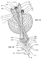
- FIG. 2A there is illustrated a cut-away view of schematic integrating sphere 1 with schematic depictions of ray bundles 38a-38d for corresponding receivers 8a-8d and associated ports 11a-11d, so that the relationship among the viewing beams of a preferred embodiment may be visualized. Also, referring to FIG. 2B, placed in relation to FIG.
- FIGS. 2A and 2B there is shown a projection onto a plane parallel to the sample surface of receiver view ports 11a-11d, viewing axes 26c and 26d (and their projections) of SCI ports 11c and 11d, and viewing axes 26a and 26b of SCE ports 11a and 11b, so that the mutual relationships of the ports and viewing axes at the rear (i.e., top portion away from sample port 7) of the integrating sphere may be more easily visualized.
- FIGS. 2A and 2B the schematic depiction of ray bundles preserves the general spatial orientation, but does not preserve the relative sizes, of viewing beams and ports shown in FIGS. 1A-1E. Also identified for reference in FIG.
- FIG. 2A and 2B together show the relationship between the ports and the specular components of the beams after reflecting off the sample.
- FIGS. 1A-1E illustrate an embodiment of an integrating sphere having multiple viewing ports, with all of the viewing ports have equal viewing angles, the two SCI ports having different sample areas of view, and the two SCE ports also have two different sample areas of view.
- the SCE ports are disposed opposite each other such that each excludes the specular components for the receiver of the other, thus reducing the overall port area of the integrating sphere.
- the maximum number and size of ports is limited by the sphere diameter which, in order to comply with existing standards, cannot have a total port area (sum of all apertures) that exceeds a certain percentage (3 to 5%, depending on the standards of choice) of the total internal surface area of the sphere.
- the sample port must be slightly larger than the overall region viewed by the receivers to allow for sample translucency (according to existing standards) and to allow for alignment tolerances.
- the azimuth angles typically are chosen to adequately separate the viewing ports from one another and from portions of the sphere comprising the origins of specular light for the SCI receivers.
- These origins of specular light are areas of the sphere surface that are opposite their respective SCI receiver apertures as mirrored from the sample surface, and are of a size that includes preferably all rays that the receiver optics collect by such specular reflection from the sample surface. No ports should intrude those portions of the sphere surface so described.
- Light traps (SEP ports) or other SCE ports used to remove the specular origin for SCE receivers must be of sufficient size to exclude preferably all rays that the receiver optics would collect by specular reflection from the sample surface.
- the size of the receiver ports, specular exclusion ports and specular inclusion origins required are dependent on several parameters of each respective receiver design, including: the sample area-of-view size, the receiver subtense angle, the aperture and focal conjugate positions of a beam forming optic if used (such as a lens), aberration characteristics of the beam forming optic, margin for each beam to ports (respective receiver aperture and specular exclusion) as prescribed by existing standards and/or alignment tolerances, size of the integrating sphere, etc.
- the receivers' axes are at a same predetermined angle from the sample normal axis, and converge to a common point on the sample surface, the point forming the center of the sample port aperture.
- the illustrative integrating sphere of FIGS. 1A-1E may include two additional SCE ports which are opposite to each other (or a single additional SCE port with opposing trap).
- the additional opposing SCE ports may be: (i) azimuthally displaced by about 0° (or, equivalently, by 180°) but at different viewing angles, each one of the additional SCE ports having any general viewing angle and/or area-of view, or (ii) displaced azimuthally by an angle not equal to about 0° (or equivalently, 180°) and having any viewing angles, including viewing angles equal to each other and to those of SCE ports 11a and 11b.
- SCI ports 11c and 11d alternatively may be displaced by different azimuthal angles (e.g., 90°) and/or disposed at different viewing angles from each other and/or modified to have the same viewing area. Further, one or more additional SCI ports may be added at any appropriate locations on the integrating sphere.
- azimuthal displacement e.g. of about 90°
- various appearance or surface characteristics e.g., striations, texture, etc.
- the sample e.g., fabric, weaves, embossings, etc.
- viewing axes may intersect the sample at different locations and the corresponding viewing beams may view overlapping sample regions (e.g., a larger viewing area of a first viewing beam encompassing a smaller viewing area of a second viewing beam, or may view two viewing areas each viewing both a common and a separate viewing region) or non-overlapping sample regions.
- Each sample region may be viewed by more than one viewing beam.
- an integrating sphere according to the present invention includes myriad features, advantages, and attendant advantages.
- advantages of receiving a plurality of viewing beams in parallel include: multiple data sets may be provided by a single measurement step, no moving parts or time delay required to change modes (e.g., SCE, SCI, different areas of view for SCE and/or SCI), electrical power is efficiently used (e.g., reduced time needed to power lamp compared to multiple measurements, no parts need be electromechanically moved), component sizes may be small, and overall structure will be durable (e.g., from no moving parts).
- SCI and SCE modes for a given area-of-view can quickly and conveniently provide an estimate of the gloss of the sample surface.
- the presence of multiple areas-of-view provides capability for quickly measuring or estimating sample uniformity and/or sample translucency.
- various azimuthal angles between SCE and/or SCI provide the ability to extract other appearance parameters (in addition to the color) from the data sets acquired, such as surface flatness or texture. Having a simultaneous reference measurement also provides optimum correction.
Landscapes
- Physics & Mathematics (AREA)
- Spectroscopy & Molecular Physics (AREA)
- General Physics & Mathematics (AREA)
- Health & Medical Sciences (AREA)
- Life Sciences & Earth Sciences (AREA)
- Chemical & Material Sciences (AREA)
- Analytical Chemistry (AREA)
- Biochemistry (AREA)
- General Health & Medical Sciences (AREA)
- Immunology (AREA)
- Pathology (AREA)
- Investigating Or Analysing Materials By Optical Means (AREA)
- Spectrometry And Color Measurement (AREA)
Description
- This invention relates generally to integrating spheres and, more particularly, to an integrating sphere with multiple ports for concurrently receiving light directly reflected from a sample under test.
- The use of integrating spheres for the optical measurement geometry in reflectance colorimetry is a standard practice, and is described in the Commission Internationale De L'Eclairage (CIE) Publication Number 15.2 (Colorimetry), 1986. An integrating sphere is an apparatus with an interior cavity (typically spherical) having a highly reflective, optically diffuse white surface. The simplest integrating sphere design contains two apertures, one which admits light and another which serves as a measurement port where the amount of light on the surface of the sphere can be measured. An integrating sphere has the property that at any point on the inner surface of the sphere the illumination is essentially independent of the direction and location of the incident beam as well as the size of the beam; the inner surface is uniformly illuminated throughout, except at the point of direct illumination. Integrating spheres are used in colorimetry for the precise determination of color for a sample under test.
- A common practice in colorimetry is to measure a sample with the specular component of reflection (mirror-like reflection from the surface) either included (SCI mode) or excluded (SCE mode). Other aspects of measurement may include selection of the size of the measured sample surface, spectral content of the illumination, and angle of receiver beam with respect to the sample normal. Instruments designed for colorimetry traditionally measure the sample one configuration at a time (e.g. SCI or SCE mode with a single size of measured area), usually requiring a change of configuration or another instrument to select another mode combination. For example, most integrating-sphere colorimeters are capable of measuring the sample with the specular component either included or excluded. Changing between SCI and SCE modes is usually achieved by the use of a movable segment of the integrating sphere which removes the specular component for SCE measurements or includes the specular component for SCI measurements. In such an instrument, the included/excluded option requires separate measurements with a time between to move the segment and mechanical means to do so.
- Many instruments are capable of selecting the size of the area of the sample surface to be measured. Size selection is usually done with a "zoom" optical system or movable lenses/apertures. In such instruments, changing the size of the measurement area requires separate measurements with a time between to move the lens and mechanical means to do so.
- Many instruments use a second optical path as a reference measurement to normalize/compensate for changes in the illumination. Such common practice is generally referred to as "dual beam" optics. For the purposes of the discussion herein, such a reference path is not considered a "measurement" path, and is not part of the "multi-channel" principle.
- There are some colorimetry instruments with multiple measurement paths currently available. One known example measures the sample SCI and SCE simultaneously with two measurement paths. The instrument is described in U.S. Patent Number 5,369,481 ("the '481 patent"). The primary path measures the sample in SCI mode at multiple wavelengths. The secondary path measures the sample in SCE mode at one wavelength, and the remaining wavelengths are calculated based on the SCI value at the common wavelength and theoretical knowledge of the wavelength dependence of the specular reflection of the sample. The '481 patent constrains the simultaneous SCE and SCI paths (presumably measuring the same sample area-of-view size) to being "opposite" each other relative to the sample axis normal, and describes only this arrangement of an SCI and SCE port, the number of measurement paths limited to just these two plus the conventional reference path.
- Other instruments are equipped with multiple measuring "paths" which measure the color of the sample in one measurement path and measure a different parameter of the sample's appearance, such as gloss, with a second measurement system. An example includes the Color and Appearance Technology, Inc. SPECTRO/plus TM Spectrophotometer. The instrument provides a separate measurement system for the gloss; this separate measurement path does not measure the "color" of the sample and has a unique geometry specific to gloss measurement standards, such as ASTM D523, published by the American Society for Testing and Materials (ASTM) of Philadelphia, PA. Therefore, the SPECTRO/plus TM only has one color measurement path.
- There remains a need, therefore, for further improvements in integrating spheres, and particularly, for an integrating sphere which is capable of measuring multiple parameters, such as various specular component modes and/or areas-of-view per specular component mode, without the need for successive measurements and/or reconfiguration.
- DE-A-44 23 698 discloses an integrating sphere comprising ports, sensors, one or more light sources for an diffusely illuminating, using inner wall parts, a sample, a sample port, apertures or lenses, for measuring the directed and diffuse degree of a reflection, wherein the inner wall of the sphere is white coated. The one ore more light sources are arranged such that no light beam is directly directed to the sample and/or to the sensors. The inner wall parts are regions of the inner wall of the sphere which have different luminance, preferably black and white. In one embodiment, the sensor is constraint by apertures or lenses such that the sensor only receives the black port via the sample. Thus, in view of the sensors, the port and the corresponding inner wall are in coincidence. Furthermore, the optical apertures and/or lenses are arranged, such that they only can receive the sample port which is covered by the sample.
- The present invention overcomes the above, and other, limitations of the prior art and the background art by providing an integrating sphere according to
claim 1. - According to the first aspect of the invention, the first and second lines preferably intersect the sample surface at a common point.
- Preferably the first and second angles are equal.
- Additional aspects, features, and advantages of the invention will be understood and will become more readily apparent when the invention is considered in the light of the following description made in conjunction with the accompanying drawings, wherein:
- Figure 1A depicts an isometric view, with certain features of the receivers exposed for clarity, of an integrating sphere according to an embodiment of the present invention;
- Figure 1B depicts a plan (top) view, from the receiver side, of the integrating sphere, also with certain features of the receivers spaced away for clarity;
- Figure 1C is a cross-sectional view of the integrating sphere along line IC-IC of Figure 1B, with certain features of the receivers exposed for clarity;
- Figure 1D is a cross-sectional view of the integrating sphere along line ID-ID of Figure 1B, with certain features of the receivers exposed for clarity;
- Figure 1E is a cross-sectional view of the integrating sphere along line IE-IE of Figure 1D;
- Figure 2A illustrates a schematic cut-away view of the integrating sphere of Figures 1A-1E, with schematic depictions of ray bundles for the receivers and associated ports, so that the relationship among the viewing beams of a preferred embodiment may be visualized;
- FIG. 2B shows a projection onto a plane parallel to the sample surface of the receiver viewing ports and viewing axes, as depicted in FIG. 2A, so that the mutual relationships of the ports and viewing axes at the rear (i.e., top portion away from the sample port) of the integrating sphere of FIGS. 1A-1E may be more easily visualized.
-
- The present invention provides an integrating sphere which features the capability of multiple measurement modes (e.g., multiple SCE, SCE and SCI, multiple SCI), multiple areas-of-view for a given measurement mode, multiple viewing angles per measurement mode, and combinations thereof, as will be more fully appreciated hereinbelow. It is noted that the term integrating sphere is not intended to limit the interior cavity to a spherical shape, but is used, as understood by one of ordinary skill in the art, to refer to a class of instruments used for measuring light reflectance of a test sample; different shapes of the interior cavity may be implemented.
- Prior to describing illustrative embodiments of the invention, certain terminology is introduced for purposes of consistency and clarity of exposition in describing viewing conditions (e.g., spatial/optical location, orientation, and/or relationship of, between, or among port(s), sample, viewing beam(s), etc.) for an integrating sphere which is used in a diffuse reflectance measurement configuration to diffusely illuminate a test sample located at a sample port, and to receive optical radiation reflected from the test sample into receivers associated with viewing ports of the integrating sphere. Conventional colorimeters are often of reverse geometry, that is, with the illumination beam impinging directly on the sample and the detection path receiving light from the wall of the integrating sphere, which integrates the light reflected by the sample. As will be more fully appreciated hereinbelow, the present invention generally is not compatible with such reverse geometry; thus, the terminology used herein applies to the "non-reverse" geometry described hereinabove according to a diffuse reflectance measurement configuration.
- As used herein, a port generally refers to a region of the integrating sphere in which the highly reflective, optically diffuse inner surface is absent, and typically includes an aperture formed through the inner wall. A colorimeter integrating sphere includes a sample port and one or more viewing ports, and, as described hereinbelow, may also include a specular exclusion port (SEP) and/or a reference port.
- Generally, a viewing port has an associated receiver and is characterized by a viewing beam representing the ray bundle of optical radiation received by the associated receiver directly from optical radiation reflected by the sample. The areal cross section of the viewing beam of a receiver at the associated viewing port may be less than or equal to the overall cross-sectional area of the viewing port itself. Where the port area is greater than the receiver area, the region of the port surrounding the receiver portion typically has low reflectivity.
- A ray viewing angle refers to the angle between a ray of the viewing beam and the normal to the sample surface where the ray intersects the sample surface. A viewing beam plane refers to a plane defined by a ray in the viewing beam and the normal to the sample surface at the intersection of the sample surface and the ray. An azimuthal angle between two viewing beams is represented by the angle, in a plane perpendicular to a sample normal, between two viewing planes of the respective viewing beams.
- Generally, a viewing beam may include rays which deviate from each other (i.e., are not parallel) within some range (e.g., the incorporated CIE publication prescribes that the angle between the viewing beam axis and any ray of the viewing beam should not exceed 5°), thus resulting in a finite range of azimuthal angles of the viewing rays relative to a given plane, as well as a finite range of viewing angles for the viewing beam. Since, however, a viewing beam is typically symmetric about a viewing axis (i.e., the central axial ray of the viewing beam), this viewing axis is typically used for describing the (effective) viewing angle for the viewing beam as well as the (effective) azimuthal angle relative to the viewing beam.
- Also as used herein, generally for SCE mode, a second port is sometimes said to be opposite relative to a first port (also referred to the first port having an opposing port) if a mirror image beam of the first port's viewing beam mirrored from the sample surface (i.e., each ray of the ray bundle specularly reflected by the sample surface) is substantially overlapped by (e.g., encompassed by) the second port such that the specular component of the first port is completely or effectively excluded. Stated alternatively, the second port encompasses substantially the entire region from which optical radiation specularly reflected from the sample surface into the viewing beam of the first port would originate if the second port were not there (i.e., if the region were diffusely scattering). Stated yet another way, the second port is located at the portion of the integrating sphere wall corresponding to substantially all specular (regular) components for the first port.
- Accordingly, two ports are said to be opposite each other if the first port is opposite the second port (as described) and the second port is also opposite the first port such that the mirror image beam of the second port's viewing beam mirrored from the sample surface is substantially overlapped by the first port. It is noted that because a port's receiver area may be smaller than the port's area, if two ports are opposite each other, it does not necessarily follow that the viewing beams view overlapping sample surface regions or that the viewing beams have equal viewing angles: the mirror image of each viewing beam may project into the extra-receiver region of the opposing port, and the extra-receiver region of the port(s) may be of sufficient area to allow for differences in viewing angles and/or viewed sample surface regions. For instance, adjacent, non-concentric (e.g., non-overlapping) sample surface regions may be viewed by ports which are opposite to each other and have the same viewing angle; or, a common, overlapping surface region may be viewed by ports which are opposite to each other and have slightly different viewing angles.
- It may be understood in accordance with this terminology that a second port may be opposite relative to a first port but the first port may not be opposite to the second port: the viewing beam of the second port mirrored from the sample surface may not be substantially overlapped by the first port, whereas the viewing beam of the first port mirrored from the sample surface may be substantially overlapped by the second port. For instance, the first port and the second port (i.e., their viewing planes) may be azimuthally displaced by about 180° but with unequal viewing angles such that the second port encompasses a region of the integrating sphere inner surface from where the regular component for the first port receiver would originate but the viewing angle of the second port is such that the first port is not located at the region from where the specular component for the first port arrives. Alternatively, the first and second ports may be azimuthally displaced by about 180° with equal viewing angles, but viewing non-concentric (e.g., non-overlapping) sample surface regions, such that the second port encompasses a region of the integrating sphere inner surface from where the regular component for the first port receiver would originate but the viewed sample region displacement is such that the first port is not located at the region from where the specular component for the first port arrives. In another illustrative alternative, two ports may have any respective combination of viewing angles (including equal viewing angles), and may be azimuthally displaced by any angle not equal to about 180° with the first port's projected beam substantially overlapped by the second port, the ports thus viewing non-concentric (e.g., non-overlapping) surface regions of the sample.
- It also follows from this terminology that a second port is said to be non-opposite to a first port if the first port's viewing beam mirrored from the sample surface (i.e., the projection of the first port's viewing beam) is not substantially overlapped by the second port, the first port viewing beam having a not insubstantial specular component. In accordance with this general terminology for describing oppositely disposed ports, it also follows that two ports are non-oppositely disposed if neither port is opposite relative to the other port. For instance, the ports (i.e., their viewing planes) may be displaced by an azimuthal angle different from 180° and have any combination of viewing angles provided neither port's viewing beam projection is substantially overlapped by the other port. Alternatively, it may be appreciated that two non-oppositely disposed ports (i.e., their viewing planes) may nevertheless be azimuthally displaced by about 180° if, for example, they have sufficiently different viewing angles and/or they view sufficiently non-concentric (e.g., non-overlapping) sample regions, such that the projection of each beam is not substantially overlapped by the other port.
- It is understood that the foregoing description of spatial relationships between ports (and their viewing beams) is a general one which depends on the relative orientations of the viewing beams with respect to the sample plane (e.g., their respective viewing angles and viewing regions, and their relative azimuthal displacement), and which does not depend on a specific integrating sphere geometry or on a predetermined relationship of the viewing beams to each other or to the integrating sphere geometry.
- Typically, however, and in accordance with a preferred embodiment of the invention described hereinbelow, each viewing port has a viewing beam that is directed towards the sample along a viewing axis about which the viewing beam is symmetric and which intersects the sample plane at a common point which is typically also the point of intersection of the sample plane by a normal thereto which is a central axis of the integrating sphere (assuming the integrating sphere has a spherical cavity, this central axis passes through the center of the spherical cavity and the center of the sample port). Such symmetry of the viewing beams with respect to a common axis simplifies certain descriptions of relationships between or among ports. For instance, if two ports have equal viewing angles and are azimuthally displaced by about 180°, then they are opposite each other. It is understood, however, that the present invention is not limited to ports having such spatial symmetry with respect to a common axis which is symmetric relative to the integrating sphere cavity. It is also understood that the foregoing terminology is simply a chosen convention for clarity of exposition, and that there are other ways of describing the spatial relationships between or among ports and their viewing beams.
- Referring now to FIGS. 1A-1E there is shown an integrating
sphere 1 according to an embodiment of the present invention. More specifically: FIG. 1A depicts an isometric view, with certain features of the receivers exposed for clarity, of an integrating sphere according to an embodiment of the present invention; FIG. 1B depicts a plan (top) view, from the receiver side, of the integrating sphere, also with certain features of the receivers exposed for clarity; FIG. 1C is a cross-sectional view of the integrating sphere along line IC-IC of FIG. 1B; FIG. 1D is a cross-sectional view of the integrating sphere along line ID-ID of FIG. 1B; and FIG. 1E is a cross-sectional view of the integrating sphere along line IE-IE of FIG. 1D. - In more detail, integrating
sphere 1 includes two halves to facilitate construction: the two halves may be machined properly to fit one within the other, and appropriately secured with standard fastening mechanisms. Integratingsphere 1 includes a cavity having a highly reflective, optically diffuse surface 1a illuminated with a light source 2 (lamp) which may be coupled to the integratingsphere 1 in a conventional way using an entrance port 3 (aperture in the integrating sphere). Power to the lamp is supplied via lamp leads 32a, 32b, and 32c. By way of example, in an embodiment of the invention, thelight source 2 may be a pulsed lamp of high intensity, short duration, and with a full "white" spectrum, such as a pulsed Xenon lamp. The effect is to diffusely illuminatesample 6 atport 7, in a conventional way. - In the present embodiment,
lamp 2 is external to the integratingsphere 1 cavity, housed in alamp cavity 30 adjoined to integratingsphere 1.Lamp 2 may alternatively be placed at least partially internal the cavity of integratingsphere 1, and may be placed substantially internal to the integrating sphere cavity to achieve the following advantages: optical flux efficiency, mechanical simplicity, small size, and reduction of port apertures which allows a smaller integratingsphere 1 to be used for a givensample port 7 size while conforming to standards for integrating sphere design. Also, in accordance with conventional practice, the lamp may be external to the sphere and projection optics (e.g., lens, etc.) may be used to relay or project flux from the lamp through the entrance port and to a spot at the far side of the integrating sphere interior. - A baffle 4a with highly reflective, optically diffuse surface is used in a conventional way to block light rays from directly illuminating the sample 6 (shown in FIGS. 1C and 1D, only) from the lamp, or from the entrance port 3 if used. Similarly,
baffle 4b prevents light rays originating at entrance port 3 orlamp 2 from directly illuminating portions of the sphere surface from where specular flux for the SCI receivers originates. - As shown, diffusely illuminated
sample 6 is viewed by multipleoptical receivers 8a-d (i.e., four receivers in the present embodiment), each of which receives a portion of optical radiation reflected fromsample 6 and provides it to a sensor or detector used to analyze the spectral content of the received optical radiation. More particularly, shown are multiple viewing ports including specular-component-excluded (SCE)port 11a,SCE port 11b, specular-component-included (SCI)port 11c, andSCI port 11d. Each port has an associated receiver comprising associated receiver optics (shown exposed) according to the present embodiment:SCE port 11a has areceiver 8a includingaperture stop 22a,lens 24a, andfiber 17a;SCE port 11b hasreceiver 8b includingaperture stop 22b,lens 24b, and fiber 17b;SCI port 11c hasreceiver 8c including aperture stop 22c, lens 24c, andfiber 17c;SCI port 11d has areceiver 8d includingaperture stop 22d, lens 24d, and fiber 17d. Eachreceiver 8a-d is directed atsample port 7 along a corresponding one ofviewing axes sample 6. It is understood that actual components of the receivers may differ, depending on design criteria, applications, preference, etc. - The
optical receivers 8a-d of the present embodiment are located at a same predetermined viewing angle from the sample normal (less than 10° to comply with standards for colorimetry, 8° in the present embodiment) and each has its own associatedreceiver viewing port 11a-d in the integratingsphere 1. For each viewing mode (i.e., SCE and SCI), the receivers have two subtense angles, corresponding to two sample area sizes. Theoptical receivers 8a-d and their respectivereceiver viewing ports 11a-d are displaced azimuthally, thereby advantageously maintaining the same predetermined viewing angle from the sample normal, and the azimuthal displacements are chosen to conveniently fitoptical receivers 8a-d (and their associatedviewing ports 11a-d), each designed with a combination of chosen parameters. The parameters include, but are not limited to, the measured size of the sample surface, the subtense angles of the receivers, and the inclusion (SCI) or exclusion (SCE) of the specular-reflected light. Additional and non-exclusive parameters (not used in the present embodiment) include multiple viewing angles, and different viewing regions of the sample surface (e.g., non-overlapping, non-concentric). - Integrating
sphere 1 includes one SCE mode receiver and one SCI mode receiver for each of two different measured areas-of-view (four receivers total). The twoSCE receivers viewing axes SCE ports SCE receivers SCI receivers SCE receivers - As described, in the embodiment of the invention illustrated in Figures 1A-1E, each SCE port is designed to exclude substantially all specular components for the opposing SCE receiver. Such a shared arrangement of SCE/viewing ports advantageously reduces the total port area required to implement a plurality of SCE ports.
- As with frequent conventional practice, integrating
sphere 1 preferably includes an added receiver, having associatedreference port 16, which provides a measurement of the illumination which is not a direct reflection fromsample 6 and preferably not directly incident fromlamp 2 or lamp port 3. The viewing beam received viareference port 16 is referred to as a reference beam, and can be used to correct or to control thelamp 2 fluctuations and to compensate for the influence of thesample 6 reflectance on the integratingsphere 1 illumination. In FIGS. 1A-1D,reference port 16 location and its associated receiver characteristics (e.g., viewing axis orientation, subtense angle) are such that only light diffusely reflected from optically diffuse surface 1a of integratingsphere 1 is received. As shown, in order to facilitate common orientation of optical fibers for the present embodiment, the reference beam is conveniently redirected byfold mirror 36 into an optical fiber (not shown) coupled toreference fiber mount 34. It is appreciated that for the current invention, this reference path is not considered or counted as one of the multiple measurement paths. - The spectral content of the optical radiation collected (received) by each of the multiple receivers is analyzed by any of a variety of conventional means, such as filters or spectroscopic optics and appropriate signal processing (not illustrated). Preferably, the optical radiation collected (received) concurrently (in parallel) by the multiple
optical receivers 8a-d is detected (i.e., converted from an optical to an electrical signal) in parallel for each receiver, and further, is also detected in parallel spectrum-wise (i.e., for each receiver, the complete spectrum is detected in parallel). In addition, as more fully described hereinbelow, the optical radiation received by the multipleoptical receivers 8a-d is detected substantially simultaneously. Analysis of the detected signals may be performed, for example, in order to condition the detected signal and calculate the sample's color using standard formulae, as in the incorporated CIE reference. For clarity, it is noted that, as used herein, receiving optical radiation is distinguished from detecting optical radiation: the former is used to refer to optical radiation scattered/reflected from the sample surface being coupled into (accepted by) a receiver, whereas the latter is used to refer to received optical radiation being sensed (e.g., converted to an electrical signal) by a detector. Moreover, as used herein, receivers (or ports) are said to concurrently receive optical radiation when optical radiation scattered/reflected from the sample impinges on the receivers in parallel; this concurrent reception does not mean that the concurrently received optical radiation is necessarily also detected concurrently or in parallel, although, as described hereinabove and more fully hereinbelow, such concurrent or parallel detection is generally preferable. - In a preferred embodiment of the present invention, such parallel detection is implemented by a single spectrometer with a two dimensional detector array and a segmented entrance slit and a single diffraction grating, as described by Palumbo et al. in commonly assigned U.S. application Serial No. 09/041,233, entitled "Concentric Spectrometer", filed March 12, 1998. Each segment of the slit is illuminated by a corresponding receiver path, which may be accomplished with fiber optic light guides 17a-17d. Thus, the multiple
optical receivers 8a-8d can be conveniently and advantageously detected simultaneously using a single common spectrometer. Additionally, the reference beam may also be advantageously detected and processed in parallel by such a multi-channel spectrometer. It may be appreciated, however, that alternative apparatuses and/or methods may be implemented for concurrently, but not necessarily precisely simultaneously, detecting the optical signals received in parallel by the different SCI/SCE receivers. For instance, signal detection may be time multiplexed among the channels. Alternatively, even where parallel detectors are used, the channels need not be synchronously sampled; e.g., each channel may be independently gated and/or have a different sampling rate and/or sampling time. - Referring now to FIG. 2A, there is illustrated a cut-away view of schematic integrating
sphere 1 with schematic depictions ofray bundles 38a-38d for correspondingreceivers 8a-8d and associatedports 11a-11d, so that the relationship among the viewing beams of a preferred embodiment may be visualized. Also, referring to FIG. 2B, placed in relation to FIG. 2A, there is shown a projection onto a plane parallel to the sample surface ofreceiver view ports 11a-11d, viewing axes 26c and 26d (and their projections) ofSCI ports viewing axes SCE ports azimuthal displacement angle 12 betweenSCI ports central points 18 of origination of specular inclusion viewing beams at the rear (i.e., internal surface away from the sample port) of the integratingsphere 1, as would be reflected from the specular reflecting surface of thesample 6. FIG. 2A and 2B together show the relationship between the ports and the specular components of the beams after reflecting off the sample. - Accordingly, it is appreciated that in accordance with the present invention, FIGS. 1A-1E illustrate an embodiment of an integrating sphere having multiple viewing ports, with all of the viewing ports have equal viewing angles, the two SCI ports having different sample areas of view, and the two SCE ports also have two different sample areas of view. Advantageously, the SCE ports are disposed opposite each other such that each excludes the specular components for the receiver of the other, thus reducing the overall port area of the integrating sphere.
- It is appreciated that various alternative implementations of the present invention are possible based, as described above, on selection of various parameters including specular component types (i.e., SCI mode and/or SCE mode), number of ports, viewing angles, azimuthal displacements, area-of-view for each port, subtense angles, and viewed sample region for each port. Development of a given design may be dependent not only on certain physical constraints or guidelines, but also on the application or market. For instance, in some applications it is desireable to have a large area-of-view to measure a substantial portion of the sample that provides an average color of a surface that has some variation using a single measurement. It may alternatively or additionally be desireable to have a very small area-of-view to measure a sample that is of small dimension, or a small portion of a multi-colored surface such as a printed pattern or a color bar on a proof sheet, or even to measure the small scale variations of a larger colored surface. Having substantially different, large and small, area-of-views in the same colorimeter may also be generally desireable in order to provide a single integrating sphere having utility for many applications (i.e., multipurpose) or for detecting variations in a sample.
- It is understood that the maximum number and size of ports is limited by the sphere diameter which, in order to comply with existing standards, cannot have a total port area (sum of all apertures) that exceeds a certain percentage (3 to 5%, depending on the standards of choice) of the total internal surface area of the sphere. As also is known, the sample port must be slightly larger than the overall region viewed by the receivers to allow for sample translucency (according to existing standards) and to allow for alignment tolerances.
- The azimuth angles typically are chosen to adequately separate the viewing ports from one another and from portions of the sphere comprising the origins of specular light for the SCI receivers. These origins of specular light are areas of the sphere surface that are opposite their respective SCI receiver apertures as mirrored from the sample surface, and are of a size that includes preferably all rays that the receiver optics collect by such specular reflection from the sample surface. No ports should intrude those portions of the sphere surface so described. Light traps (SEP ports) or other SCE ports used to remove the specular origin for SCE receivers must be of sufficient size to exclude preferably all rays that the receiver optics would collect by specular reflection from the sample surface.
- The size of the receiver ports, specular exclusion ports and specular inclusion origins required are dependent on several parameters of each respective receiver design, including: the sample area-of-view size, the receiver subtense angle, the aperture and focal conjugate positions of a beam forming optic if used (such as a lens), aberration characteristics of the beam forming optic, margin for each beam to ports (respective receiver aperture and specular exclusion) as prescribed by existing standards and/or alignment tolerances, size of the integrating sphere, etc.
- As described for the hereinabove embodiment, there is an advantage in opposing SCE ports such that they each effectively act as a specular exclusion port for the receiver of the other SCE port. Such an arrangement reduces the number of ports required for a given number of receivers, and allows more receivers of given parameters to be used in a sphere of the same size.
- In the hereinabove embodiment, the receivers' axes are at a same predetermined angle from the sample normal axis, and converge to a common point on the sample surface, the point forming the center of the sample port aperture. For certain applications, however, there may be utility in having receivers at different angles from the sample normal axis and/or not converging to a common point on the sample.
- It may be appreciated, therefore, that there are many possible variations for implementing an integrating sphere in accordance with the present invention.
- Alternatively, the illustrative integrating sphere of FIGS. 1A-1E may include two additional SCE ports which are opposite to each other (or a single additional SCE port with opposing trap). For example, relative to opposing
SCE ports SCE ports - Additionally, it may be appreciated that there are myriad implementations possible with respect to orientation and arrangement of SCI ports. For instance,
SCI ports - In these arrangements of two or more SCE ports and/or two or more SCI ports, providing azimuthal displacement (e.g,. of about 90°) between or among SCE ports and/or between or among SCI ports may be useful for measuring and/or accounting for various appearance or surface characteristics (e.g., striations, texture, etc.) of the sample (e.g., fabric, weaves, embossings, etc.) which may give rise to azimuthally anisotropic reflectance.
- As an additional example of variations within the purview of the present invention, although the embodiment and illustrative variations described hereinabove includes all viewing beam axes converging to a common point at the sample, alternative embodiments may be implemented wherein viewing axes of different viewing beams do not all converge onto a common point. For instance, viewing axes may intersect the sample at different locations and the corresponding viewing beams may view overlapping sample regions (e.g., a larger viewing area of a first viewing beam encompassing a smaller viewing area of a second viewing beam, or may view two viewing areas each viewing both a common and a separate viewing region) or non-overlapping sample regions. Each sample region may be viewed by more than one viewing beam.
- As may be appreciated from the foregoing description, and as may be further appreciated by practicing the present invention, an integrating sphere according to the present invention includes myriad features, advantages, and attendant advantages. For instance, advantages of receiving a plurality of viewing beams in parallel include: multiple data sets may be provided by a single measurement step, no moving parts or time delay required to change modes (e.g., SCE, SCI, different areas of view for SCE and/or SCI), electrical power is efficiently used (e.g., reduced time needed to power lamp compared to multiple measurements, no parts need be electromechanically moved), component sizes may be small, and overall structure will be durable (e.g., from no moving parts). The presence of both SCI and SCE modes for a given area-of-view can quickly and conveniently provide an estimate of the gloss of the sample surface. The presence of multiple areas-of-view provides capability for quickly measuring or estimating sample uniformity and/or sample translucency. Additionally, various azimuthal angles between SCE and/or SCI provide the ability to extract other appearance parameters (in addition to the color) from the data sets acquired, such as surface flatness or texture. Having a simultaneous reference measurement also provides optimum correction. These features and advantages provide substantial benefits particularly well suited for portable instruments, as well as for convenient non-portable applications.
- Although the above description of illustrative embodiments of the invention, and various modifications thereof, provides many specificities, these enabling details should not be construed as limiting the scope of the invention, and it will be readily understood by those persons skilled in the art that the present invention is susceptible to many modifications, adaptations, and equivalent implementations without departing from this scope and without diminishing its attendant advantages. It is therefore intended that the present invention is not limited to the disclosed embodiments but should be defined in accordance with the claims which follow.
Claims (5)
- An integrating sphere (1), comprising a housing member having a cavity with an optically diffuse and highly reflective inner surface (1a), said housing member including a sample port (7) where a sample (6) is placed, a light source (2) for diffusely illuminating said sample port (7) and to first receiver for receiving optical radiation reflected from said sample (6) along a first line (26a - 26d) extending at a first angle relative to a first normal to the sample (6) at the intersection of said first line (26a - 26d) and the sample surface, and a second receiver for receiving, concurrently with the reception of optical radiation by said first receiver optical radiation reflected from said sample (6) along a second line (26a - 26d) extending at a second angle relative to a second normal to the sample (6) at the intersection of said second line (26a - 26d) and the sample surface, and wherein each of said first and second receivers iswherein the origins of specular light are areas of the sphere surface opposite the respective receiver apertures as mirrored from the sample surface; wherein(i) an SCI receiver (8c, 8d) which receives optical radiation, including specular light, reflected from said sample port (7) along the corresponding first or second line (26a - 26d), or(ii) an SCE receiver which receives optical radiation reflected from said sample port (7) exclusive of specular light, the integrating sphere comprisinga) a first SCE receiver (8a, 8b) and a second SCE receiver (8a, 8b) located in opposite relationship to each other,b) a first SCI receiver (8c, 8d) and a second SCI receiver (8c, 8d) located in non-opposite relationship to each other; andc) the first SCI receiver (8c, 8d) and the second SCE receiver (8a, 8b) located in non-opposite relationship to each other,a first receiver is opposite relative to a second receiver if a mirror image beam of the second receiver viewing beam mirrored from the sample surface is substantially overlapped by the first receiver such that the specular light of the second receiver is excluded.
- The integrating sphere according to claim 1, wherein the light source (2) for diffusely illuminating said sample part (7) is an optical radiation source (2) which provides optical radiation directed toward said inner surface (1a): wherein the first and second receivers (8a - 8d) are directed toward said sample port (7) along said first and second line (26a - 26d) extending at a first and second angle relative to a first and second normal to the sample (6) at the intersection of said first and second line (26a - 26d) and the sample surface, respectively.
- The integrating sphere according to one of the claims 1 or 2, wherein said first and second lines intersect the sample surface at a common point.
- The integrating sphere according to claim 1, wherein said first and second angles are equal.
- The integrating sphere according to one of the claims 2 or 3, wherein said first and second SCE receivers view different sized area-of-views of said sample.
Applications Claiming Priority (2)
| Application Number | Priority Date | Filing Date | Title |
|---|---|---|---|
| US97312 | 1998-06-12 | ||
| US09/097,312 US6424413B1 (en) | 1998-06-12 | 1998-06-12 | Multi-channel integrating sphere |
Publications (2)
| Publication Number | Publication Date |
|---|---|
| EP0964244A1 EP0964244A1 (en) | 1999-12-15 |
| EP0964244B1 true EP0964244B1 (en) | 2005-10-05 |
Family
ID=22262735
Family Applications (1)
| Application Number | Title | Priority Date | Filing Date |
|---|---|---|---|
| EP99304615A Expired - Lifetime EP0964244B1 (en) | 1998-06-12 | 1999-06-14 | Multi-channel integrating sphere |
Country Status (3)
| Country | Link |
|---|---|
| US (1) | US6424413B1 (en) |
| EP (1) | EP0964244B1 (en) |
| DE (1) | DE69927552T2 (en) |
Cited By (1)
| Publication number | Priority date | Publication date | Assignee | Title |
|---|---|---|---|---|
| US7349096B2 (en) | 2003-02-28 | 2008-03-25 | Koninklijke Philips Electronics, N.V. | Scatterometer and a method for observing a surface |
Families Citing this family (32)
| Publication number | Priority date | Publication date | Assignee | Title |
|---|---|---|---|---|
| US6734958B1 (en) * | 1999-09-17 | 2004-05-11 | Tidal Photonics, Inc. | Apparatus and methods for evaluating performance of endoscopy devices and systems |
| ES2184656T1 (en) | 2000-11-20 | 2003-04-16 | Dow Global Technologies Inc | METHOD FOR CHARACTERIZING THE ASPECT OF A PARTICULAR OBJECT, TO PREACH THE ASPECT OF AN OBJECT, AND TO MANUFACTURE AN OBJECT THAT HAS A DEFAULT ASPECT, THAT OPTIONALLY HAS BEEN DETERMINED ON THE BASIS OF A REFERENCE OBJECT. |
| US6846085B2 (en) * | 2001-01-19 | 2005-01-25 | Dbm Optics, Incorporated | Mitigating the effects of miniaturizing integrating spheres for fiber optic measurement |
| US6536736B2 (en) * | 2001-07-16 | 2003-03-25 | Agilent Technologies, Inc. | Optomechanical mount for precisely steering/positioning a light beam |
| EP1314972B1 (en) | 2001-11-26 | 2010-07-14 | X-Rite Europe GmbH | Spectrophotometer and its use |
| US6700657B1 (en) * | 2002-05-10 | 2004-03-02 | Schmitt Measurement Systems, Inc. | System and method for detecting surface roughness |
| WO2004076992A2 (en) * | 2003-02-24 | 2004-09-10 | Gretagmacbeth, Llc | Spectrophotometer and subassemblies thereof |
| US20050078911A1 (en) * | 2003-10-14 | 2005-04-14 | Mikes Thomas L. | System and method for using a concentric spectrometer to multiplex or demultiplex optical signals |
| EP2390654B1 (en) * | 2005-03-04 | 2013-09-11 | Sun Chemical Corporation | Method and apparatus for measuring the transparency of a film |
| US7365925B2 (en) * | 2006-03-30 | 2008-04-29 | Agilent Technologies, Inc. | Method of aligning optical elements |
| JP5411698B2 (en) * | 2006-10-05 | 2014-02-12 | コーニンクレッカ フィリップス エヌ ヴェ | Apparatus and method for observing the surface of a sample |
| DE102009011381A1 (en) * | 2009-03-05 | 2010-09-09 | Flore, Ingo, Dr. | Diagnostic measuring device |
| DE102009040642B3 (en) * | 2009-09-09 | 2011-03-10 | Von Ardenne Anlagentechnik Gmbh | Method and device for measuring optical characteristics of transparent, scattering measuring objects |
| US8854734B2 (en) * | 2009-11-12 | 2014-10-07 | Vela Technologies, Inc. | Integrating optical system and methods |
| US8426800B2 (en) * | 2010-09-09 | 2013-04-23 | Vela Technologies, Inc. | Integrating optical systems and methods |
| JP5985629B2 (en) * | 2012-06-15 | 2016-09-06 | パイオニア株式会社 | Photometric device |
| JP6185864B2 (en) * | 2013-06-07 | 2017-08-23 | 本田技研工業株式会社 | Integrating sphere |
| US10094711B2 (en) * | 2014-04-01 | 2018-10-09 | Shimadzu Corporation | Spectrometer and integrating sphere |
| EP3232171B1 (en) * | 2014-12-10 | 2024-06-12 | Konica Minolta, Inc. | Illumination device and reflection characteristics measurement device |
| US10989593B2 (en) * | 2015-06-26 | 2021-04-27 | Konica Minolta, Inc. | Multi-angle colorimeter that suppresses the influence of an inclination of a reference angle on a colorimetric result |
| JP6875390B2 (en) * | 2015-10-20 | 2021-05-26 | スペクトラフィ インコーポレイテッドSpectrafy Inc. | All-sky solar spectrum device and method |
| TWI560432B (en) * | 2015-12-31 | 2016-12-01 | Mpi Corp | Integrating sphere cover and integrating sphere module |
| CN110199180B (en) | 2016-10-11 | 2022-02-18 | 维多利亚联合有限公司 | Spectrometer arrangement for measuring a spectrum of a liquid sample using an integrating chamber |
| USD860825S1 (en) * | 2018-08-06 | 2019-09-24 | Li-Chuan Chen | Integrating sphere |
| US10591354B1 (en) | 2018-10-30 | 2020-03-17 | Datacolor Inc. | Simultaneous SCE and SCI measurements |
| JP7261473B2 (en) * | 2019-06-12 | 2023-04-20 | 公立大学法人大阪 | lighting equipment |
| JP7409386B2 (en) * | 2019-09-12 | 2024-01-09 | コニカミノルタ株式会社 | color measurement device |
| CN111983831A (en) * | 2020-08-07 | 2020-11-24 | 深圳市华星光电半导体显示技术有限公司 | Liquid crystal panel reflectivity detection device and detection method |
| DE102020122041A1 (en) * | 2020-08-24 | 2022-02-24 | Claas Selbstfahrende Erntemaschinen Gmbh | Optical measuring device |
| WO2023186538A1 (en) * | 2022-03-30 | 2023-10-05 | ams Sensors Germany GmbH | Optical arrangement for optoelectronic reflective measurement |
| CN114878497B (en) * | 2022-04-21 | 2025-11-11 | 深圳技术大学 | Integrating sphere for measuring absorption spectrum and measuring method thereof |
| USD1067795S1 (en) * | 2023-03-20 | 2025-03-25 | Hong-Ming Technology Co., Ltd. | Integrating sphere |
Family Cites Families (30)
| Publication number | Priority date | Publication date | Assignee | Title |
|---|---|---|---|---|
| US3998551A (en) * | 1975-11-20 | 1976-12-21 | Shigeru Suga | Device for measuring stimulus values of the color of a liquid |
| JPS609708Y2 (en) * | 1978-03-23 | 1985-04-05 | 蓊 須賀 | Integrating sphere standard light source device |
| DE2834982C3 (en) * | 1978-08-10 | 1981-02-12 | Vladimir Dipl.-Ing. 5100 Aachen Blazek | Photometer sphere |
| DE3072138D1 (en) | 1980-11-17 | 1989-02-02 | Caterpillar Inc | Surface roughness gauge |
| US4487504A (en) * | 1982-09-01 | 1984-12-11 | Pacific Scientific Instruments Company | Reflectance measuring instrument with integrating sphere |
| US4991106A (en) * | 1983-03-02 | 1991-02-05 | Alfa-Laval Ab | Method and apparatus for aligning and analyzing sample and control signals |
| US4583860A (en) * | 1983-11-30 | 1986-04-22 | The United States Of America As Represented By The Administrator Of The National Aeronautics And Space Administration | Optical multiple sample vacuum integrating sphere |
| GB8425273D0 (en) * | 1984-10-05 | 1984-11-14 | Spandrel Etab | Signal responsive to parameter of objects |
| US4673818A (en) * | 1985-11-25 | 1987-06-16 | Polaroid Corporation | Roughness measuring apparatus |
| US4995727A (en) * | 1987-05-22 | 1991-02-26 | Minolta Camera Kabushiki Kaisha | Compact diffusion light mixing box and colorimeter |
| JP2604754B2 (en) * | 1987-09-04 | 1997-04-30 | 倉敷紡績株式会社 | Spectrophotometer |
| US4881811A (en) * | 1988-02-16 | 1989-11-21 | Colorgen, Inc. | Remote color measurement device |
| IT1216681B (en) * | 1988-03-31 | 1990-03-08 | Maxmeyer Duco Mm D Spa | PORTABLE SPECTROPHOMETER. |
| DE3818815A1 (en) * | 1988-06-03 | 1989-12-14 | Zeiss Carl Fa | REMISSION MEASURING DEVICE |
| US4932779A (en) * | 1989-01-05 | 1990-06-12 | Byk Gardner, Inc. | Color measuring instrument with integrating sphere |
| US5258363A (en) * | 1989-03-21 | 1993-11-02 | Troy Investments Inc. | Superconducting integrating spheres |
| DE4030836A1 (en) * | 1990-09-28 | 1992-04-02 | Kim Yoon Ok | DEVICE FOR QUALITATIVELY AND / OR QUANTITATIVELY DETERMINING THE COMPOSITION OF A SAMPLE TO BE ANALYZED |
| US5272518A (en) * | 1990-12-17 | 1993-12-21 | Hewlett-Packard Company | Colorimeter and calibration system |
| US5268749A (en) * | 1991-07-26 | 1993-12-07 | Kollmorgen Corporation | Apparatus and method for providing uniform illumination of a sample plane |
| US5332908A (en) * | 1992-03-31 | 1994-07-26 | Siemens Medical Laboratories, Inc. | Method for dynamic beam profile generation |
| US5369481A (en) * | 1992-05-08 | 1994-11-29 | X-Rite, Incorporated | Portable spectrophotometer |
| JPH0650817A (en) * | 1992-07-29 | 1994-02-25 | Minolta Camera Co Ltd | Measuring device for optical characteristic of sample |
| JP3117565B2 (en) * | 1992-11-27 | 2000-12-18 | 松下電器産業株式会社 | Luminometer |
| JP2745102B2 (en) * | 1992-12-02 | 1998-04-28 | ローレルバンクマシン株式会社 | Coin discriminator |
| US5377000A (en) * | 1993-04-29 | 1994-12-27 | Color And Appearance Technology, Inc. | Portable appearance measuring apparatus |
| JPH07301598A (en) * | 1993-10-07 | 1995-11-14 | Masato Mamiya | Optical sensor probe |
| JP3464824B2 (en) * | 1994-03-07 | 2003-11-10 | 株式会社リコー | Optical measuring device |
| DE4423698A1 (en) * | 1994-06-24 | 1996-01-04 | Ingo Hennig | Opto-electronic measurement device for specular and diffuse reflections |
| EP0775296A1 (en) | 1995-05-26 | 1997-05-28 | Lxr Biotechnology Inc. | Multi-channel acquisition using integrating sphere |
| US5625451A (en) | 1995-11-27 | 1997-04-29 | Schmitt Measurement Systems, Inc. | Methods and apparatus for characterizing a surface |
-
1998
- 1998-06-12 US US09/097,312 patent/US6424413B1/en not_active Expired - Lifetime
-
1999
- 1999-06-14 DE DE69927552T patent/DE69927552T2/en not_active Expired - Lifetime
- 1999-06-14 EP EP99304615A patent/EP0964244B1/en not_active Expired - Lifetime
Cited By (1)
| Publication number | Priority date | Publication date | Assignee | Title |
|---|---|---|---|---|
| US7349096B2 (en) | 2003-02-28 | 2008-03-25 | Koninklijke Philips Electronics, N.V. | Scatterometer and a method for observing a surface |
Also Published As
| Publication number | Publication date |
|---|---|
| EP0964244A1 (en) | 1999-12-15 |
| DE69927552D1 (en) | 2006-02-16 |
| US6424413B1 (en) | 2002-07-23 |
| DE69927552T2 (en) | 2006-06-14 |
Similar Documents
| Publication | Publication Date | Title |
|---|---|---|
| US6424413B1 (en) | Multi-channel integrating sphere | |
| EP0569104B1 (en) | Portable spectrophotometer | |
| US6226085B1 (en) | Method and apparatus for surface effect characterization | |
| US5268749A (en) | Apparatus and method for providing uniform illumination of a sample plane | |
| KR100242670B1 (en) | Method and apparatus for spectral reflectometry and transmission measurement | |
| JP2831124B2 (en) | Spectroscopic microscope with one photometer | |
| US20120314219A1 (en) | Device for referenced measurements of reflected light and a method for calibrating such a device | |
| US6275295B1 (en) | Optical system for determining physical characteristics of a solar cell | |
| GB2024415A (en) | Apparatus for determining faults in strip material | |
| JPS6117047A (en) | Visual gloss degree measuring method | |
| US7321423B2 (en) | Real-time goniospectrophotometer | |
| US5392125A (en) | Instrument for determining visual surface properties | |
| WO2007072403A1 (en) | Optical measurement device | |
| US5815254A (en) | Transmittance and reflectance measuring spectrophotometer having dual use light channels | |
| CN1073012A (en) | The device of measuring optical fiber spectral-transmission favtor | |
| US11360024B1 (en) | Measurement arrangement for measuring diffusely reflected light and specularly reflected light | |
| EP4275022B1 (en) | Optical measurement system comprising an optical multiplexer | |
| US11953426B2 (en) | Measurement light source and measuring arrangement for detecting a reflection spectrum | |
| JPH07120323A (en) | Metal surface color measuring device | |
| JPS62148819A (en) | Photodetecting probe of spectocolorimeter | |
| JPH08159878A (en) | Illuminating and light receiving apparatus | |
| JPS61233328A (en) | Colorimetric color difference meter | |
| JPH02179428A (en) | Colorimetric apparatus for moving object having specular reflection surface |
Legal Events
| Date | Code | Title | Description |
|---|---|---|---|
| PUAI | Public reference made under article 153(3) epc to a published international application that has entered the european phase |
Free format text: ORIGINAL CODE: 0009012 |
|
| AK | Designated contracting states |
Kind code of ref document: A1 Designated state(s): DE ES FR GB IT |
|
| AX | Request for extension of the european patent |
Free format text: AL;LT;LV;MK;RO;SI |
|
| 17P | Request for examination filed |
Effective date: 20000614 |
|
| AKX | Designation fees paid |
Free format text: DE ES FR GB IT |
|
| 17Q | First examination report despatched |
Effective date: 20030711 |
|
| GRAP | Despatch of communication of intention to grant a patent |
Free format text: ORIGINAL CODE: EPIDOSNIGR1 |
|
| GRAS | Grant fee paid |
Free format text: ORIGINAL CODE: EPIDOSNIGR3 |
|
| GRAA | (expected) grant |
Free format text: ORIGINAL CODE: 0009210 |
|
| AK | Designated contracting states |
Kind code of ref document: B1 Designated state(s): DE ES FR GB IT |
|
| REG | Reference to a national code |
Ref country code: GB Ref legal event code: FG4D |
|
| PG25 | Lapsed in a contracting state [announced via postgrant information from national office to epo] |
Ref country code: ES Free format text: LAPSE BECAUSE OF FAILURE TO SUBMIT A TRANSLATION OF THE DESCRIPTION OR TO PAY THE FEE WITHIN THE PRESCRIBED TIME-LIMIT Effective date: 20060116 |
|
| REF | Corresponds to: |
Ref document number: 69927552 Country of ref document: DE Date of ref document: 20060216 Kind code of ref document: P |
|
| ET | Fr: translation filed | ||
| PLBE | No opposition filed within time limit |
Free format text: ORIGINAL CODE: 0009261 |
|
| STAA | Information on the status of an ep patent application or granted ep patent |
Free format text: STATUS: NO OPPOSITION FILED WITHIN TIME LIMIT |
|
| 26N | No opposition filed |
Effective date: 20060706 |
|
| REG | Reference to a national code |
Ref country code: FR Ref legal event code: PLFP Year of fee payment: 17 |
|
| REG | Reference to a national code |
Ref country code: DE Ref legal event code: R082 Ref document number: 69927552 Country of ref document: DE Representative=s name: SCHWABE SANDMAIR MARX PATENTANWAELTE RECHTSANW, DE Ref country code: DE Ref legal event code: R082 Ref document number: 69927552 Country of ref document: DE Representative=s name: SCHWABE SANDMAIR MARX, DE Ref country code: DE Ref legal event code: R081 Ref document number: 69927552 Country of ref document: DE Owner name: X-RITE SWITZERLAND GMBH, CH Free format text: FORMER OWNER: GRETAGMACBETH, L.L.C., NEW WINDSOR, N.Y., US |
|
| REG | Reference to a national code |
Ref country code: FR Ref legal event code: TP Owner name: X-RITE SWITZERLAND GMBH, CH Effective date: 20151215 |
|
| REG | Reference to a national code |
Ref country code: GB Ref legal event code: 732E Free format text: REGISTERED BETWEEN 20160107 AND 20160113 |
|
| REG | Reference to a national code |
Ref country code: FR Ref legal event code: PLFP Year of fee payment: 18 |
|
| REG | Reference to a national code |
Ref country code: FR Ref legal event code: PLFP Year of fee payment: 19 |
|
| REG | Reference to a national code |
Ref country code: FR Ref legal event code: PLFP Year of fee payment: 20 |
|
| PGFP | Annual fee paid to national office [announced via postgrant information from national office to epo] |
Ref country code: FR Payment date: 20180626 Year of fee payment: 20 |
|
| PGFP | Annual fee paid to national office [announced via postgrant information from national office to epo] |
Ref country code: GB Payment date: 20180627 Year of fee payment: 20 Ref country code: IT Payment date: 20180621 Year of fee payment: 20 Ref country code: DE Payment date: 20180627 Year of fee payment: 20 |
|
| REG | Reference to a national code |
Ref country code: DE Ref legal event code: R071 Ref document number: 69927552 Country of ref document: DE |
|
| REG | Reference to a national code |
Ref country code: GB Ref legal event code: PE20 Expiry date: 20190613 |
|
| PG25 | Lapsed in a contracting state [announced via postgrant information from national office to epo] |
Ref country code: GB Free format text: LAPSE BECAUSE OF EXPIRATION OF PROTECTION Effective date: 20190613 |