EP0963868B1 - Hydraulic control systems - Google Patents
Hydraulic control systems Download PDFInfo
- Publication number
- EP0963868B1 EP0963868B1 EP99304126A EP99304126A EP0963868B1 EP 0963868 B1 EP0963868 B1 EP 0963868B1 EP 99304126 A EP99304126 A EP 99304126A EP 99304126 A EP99304126 A EP 99304126A EP 0963868 B1 EP0963868 B1 EP 0963868B1
- Authority
- EP
- European Patent Office
- Prior art keywords
- pressure
- control
- actuator
- hydraulic
- roll
- Prior art date
- Legal status (The legal status is an assumption and is not a legal conclusion. Google has not performed a legal analysis and makes no representation as to the accuracy of the status listed.)
- Expired - Lifetime
Links
- 239000012530 fluid Substances 0.000 claims description 17
- 230000001133 acceleration Effects 0.000 claims description 7
- 238000005259 measurement Methods 0.000 claims description 4
- 230000004044 response Effects 0.000 claims description 4
- 239000000725 suspension Substances 0.000 claims description 4
- 230000001419 dependent effect Effects 0.000 claims description 3
- 238000012544 monitoring process Methods 0.000 claims description 3
- 238000009529 body temperature measurement Methods 0.000 description 1
- 230000007423 decrease Effects 0.000 description 1
- 238000000034 method Methods 0.000 description 1
- 230000004043 responsiveness Effects 0.000 description 1
- 239000002470 thermal conductor Substances 0.000 description 1
Images


Classifications
-
- B—PERFORMING OPERATIONS; TRANSPORTING
- B60—VEHICLES IN GENERAL
- B60G—VEHICLE SUSPENSION ARRANGEMENTS
- B60G21/00—Interconnection systems for two or more resiliently-suspended wheels, e.g. for stabilising a vehicle body with respect to acceleration, deceleration or centrifugal forces
- B60G21/02—Interconnection systems for two or more resiliently-suspended wheels, e.g. for stabilising a vehicle body with respect to acceleration, deceleration or centrifugal forces permanently interconnected
- B60G21/06—Interconnection systems for two or more resiliently-suspended wheels, e.g. for stabilising a vehicle body with respect to acceleration, deceleration or centrifugal forces permanently interconnected fluid
-
- B—PERFORMING OPERATIONS; TRANSPORTING
- B60—VEHICLES IN GENERAL
- B60G—VEHICLE SUSPENSION ARRANGEMENTS
- B60G17/00—Resilient suspensions having means for adjusting the spring or vibration-damper characteristics, for regulating the distance between a supporting surface and a sprung part of vehicle or for locking suspension during use to meet varying vehicular or surface conditions, e.g. due to speed or load
- B60G17/015—Resilient suspensions having means for adjusting the spring or vibration-damper characteristics, for regulating the distance between a supporting surface and a sprung part of vehicle or for locking suspension during use to meet varying vehicular or surface conditions, e.g. due to speed or load the regulating means comprising electric or electronic elements
- B60G17/0152—Resilient suspensions having means for adjusting the spring or vibration-damper characteristics, for regulating the distance between a supporting surface and a sprung part of vehicle or for locking suspension during use to meet varying vehicular or surface conditions, e.g. due to speed or load the regulating means comprising electric or electronic elements characterised by the action on a particular type of suspension unit
-
- B—PERFORMING OPERATIONS; TRANSPORTING
- B60—VEHICLES IN GENERAL
- B60G—VEHICLE SUSPENSION ARRANGEMENTS
- B60G17/00—Resilient suspensions having means for adjusting the spring or vibration-damper characteristics, for regulating the distance between a supporting surface and a sprung part of vehicle or for locking suspension during use to meet varying vehicular or surface conditions, e.g. due to speed or load
- B60G17/015—Resilient suspensions having means for adjusting the spring or vibration-damper characteristics, for regulating the distance between a supporting surface and a sprung part of vehicle or for locking suspension during use to meet varying vehicular or surface conditions, e.g. due to speed or load the regulating means comprising electric or electronic elements
- B60G17/018—Resilient suspensions having means for adjusting the spring or vibration-damper characteristics, for regulating the distance between a supporting surface and a sprung part of vehicle or for locking suspension during use to meet varying vehicular or surface conditions, e.g. due to speed or load the regulating means comprising electric or electronic elements characterised by the use of a specific signal treatment or control method
- B60G17/0185—Resilient suspensions having means for adjusting the spring or vibration-damper characteristics, for regulating the distance between a supporting surface and a sprung part of vehicle or for locking suspension during use to meet varying vehicular or surface conditions, e.g. due to speed or load the regulating means comprising electric or electronic elements characterised by the use of a specific signal treatment or control method for failure detection
-
- B—PERFORMING OPERATIONS; TRANSPORTING
- B60—VEHICLES IN GENERAL
- B60G—VEHICLE SUSPENSION ARRANGEMENTS
- B60G21/00—Interconnection systems for two or more resiliently-suspended wheels, e.g. for stabilising a vehicle body with respect to acceleration, deceleration or centrifugal forces
- B60G21/02—Interconnection systems for two or more resiliently-suspended wheels, e.g. for stabilising a vehicle body with respect to acceleration, deceleration or centrifugal forces permanently interconnected
- B60G21/04—Interconnection systems for two or more resiliently-suspended wheels, e.g. for stabilising a vehicle body with respect to acceleration, deceleration or centrifugal forces permanently interconnected mechanically
- B60G21/05—Interconnection systems for two or more resiliently-suspended wheels, e.g. for stabilising a vehicle body with respect to acceleration, deceleration or centrifugal forces permanently interconnected mechanically between wheels on the same axle but on different sides of the vehicle, i.e. the left and right wheel suspensions being interconnected
- B60G21/055—Stabiliser bars
- B60G21/0551—Mounting means therefor
- B60G21/0553—Mounting means therefor adjustable
-
- B—PERFORMING OPERATIONS; TRANSPORTING
- B60—VEHICLES IN GENERAL
- B60G—VEHICLE SUSPENSION ARRANGEMENTS
- B60G21/00—Interconnection systems for two or more resiliently-suspended wheels, e.g. for stabilising a vehicle body with respect to acceleration, deceleration or centrifugal forces
- B60G21/02—Interconnection systems for two or more resiliently-suspended wheels, e.g. for stabilising a vehicle body with respect to acceleration, deceleration or centrifugal forces permanently interconnected
- B60G21/06—Interconnection systems for two or more resiliently-suspended wheels, e.g. for stabilising a vehicle body with respect to acceleration, deceleration or centrifugal forces permanently interconnected fluid
- B60G21/067—Interconnection systems for two or more resiliently-suspended wheels, e.g. for stabilising a vehicle body with respect to acceleration, deceleration or centrifugal forces permanently interconnected fluid between wheels on different axles on the same side of the vehicle, i.e. the left or the right side
-
- B—PERFORMING OPERATIONS; TRANSPORTING
- B60—VEHICLES IN GENERAL
- B60G—VEHICLE SUSPENSION ARRANGEMENTS
- B60G2202/00—Indexing codes relating to the type of spring, damper or actuator
- B60G2202/10—Type of spring
- B60G2202/13—Torsion spring
- B60G2202/135—Stabiliser bar and/or tube
-
- B—PERFORMING OPERATIONS; TRANSPORTING
- B60—VEHICLES IN GENERAL
- B60G—VEHICLE SUSPENSION ARRANGEMENTS
- B60G2202/00—Indexing codes relating to the type of spring, damper or actuator
- B60G2202/40—Type of actuator
- B60G2202/41—Fluid actuator
- B60G2202/413—Hydraulic actuator
-
- B—PERFORMING OPERATIONS; TRANSPORTING
- B60—VEHICLES IN GENERAL
- B60G—VEHICLE SUSPENSION ARRANGEMENTS
- B60G2202/00—Indexing codes relating to the type of spring, damper or actuator
- B60G2202/40—Type of actuator
- B60G2202/41—Fluid actuator
- B60G2202/414—Fluid actuator using electrohydraulic valves
-
- B—PERFORMING OPERATIONS; TRANSPORTING
- B60—VEHICLES IN GENERAL
- B60G—VEHICLE SUSPENSION ARRANGEMENTS
- B60G2204/00—Indexing codes related to suspensions per se or to auxiliary parts
- B60G2204/10—Mounting of suspension elements
- B60G2204/12—Mounting of springs or dampers
- B60G2204/122—Mounting of torsion springs
- B60G2204/1224—End mounts of stabiliser on wheel suspension
-
- B—PERFORMING OPERATIONS; TRANSPORTING
- B60—VEHICLES IN GENERAL
- B60G—VEHICLE SUSPENSION ARRANGEMENTS
- B60G2204/00—Indexing codes related to suspensions per se or to auxiliary parts
- B60G2204/62—Adjustable continuously, e.g. during driving
-
- B—PERFORMING OPERATIONS; TRANSPORTING
- B60—VEHICLES IN GENERAL
- B60G—VEHICLE SUSPENSION ARRANGEMENTS
- B60G2400/00—Indexing codes relating to detected, measured or calculated conditions or factors
- B60G2400/10—Acceleration; Deceleration
- B60G2400/104—Acceleration; Deceleration lateral or transversal with regard to vehicle
-
- B—PERFORMING OPERATIONS; TRANSPORTING
- B60—VEHICLES IN GENERAL
- B60G—VEHICLE SUSPENSION ARRANGEMENTS
- B60G2400/00—Indexing codes relating to detected, measured or calculated conditions or factors
- B60G2400/50—Pressure
- B60G2400/51—Pressure in suspension unit
-
- B—PERFORMING OPERATIONS; TRANSPORTING
- B60—VEHICLES IN GENERAL
- B60G—VEHICLE SUSPENSION ARRANGEMENTS
- B60G2400/00—Indexing codes relating to detected, measured or calculated conditions or factors
- B60G2400/60—Load
-
- B—PERFORMING OPERATIONS; TRANSPORTING
- B60—VEHICLES IN GENERAL
- B60G—VEHICLE SUSPENSION ARRANGEMENTS
- B60G2400/00—Indexing codes relating to detected, measured or calculated conditions or factors
- B60G2400/70—Temperature of vehicle part or in the vehicle
- B60G2400/71—Temperature of vehicle part or in the vehicle of suspension unit
-
- B—PERFORMING OPERATIONS; TRANSPORTING
- B60—VEHICLES IN GENERAL
- B60G—VEHICLE SUSPENSION ARRANGEMENTS
- B60G2500/00—Indexing codes relating to the regulated action or device
- B60G2500/20—Spring action or springs
-
- B—PERFORMING OPERATIONS; TRANSPORTING
- B60—VEHICLES IN GENERAL
- B60G—VEHICLE SUSPENSION ARRANGEMENTS
- B60G2600/00—Indexing codes relating to particular elements, systems or processes used on suspension systems or suspension control systems
- B60G2600/02—Retarders, delaying means, dead zones, threshold values, cut-off frequency, timer interruption
-
- B—PERFORMING OPERATIONS; TRANSPORTING
- B60—VEHICLES IN GENERAL
- B60G—VEHICLE SUSPENSION ARRANGEMENTS
- B60G2600/00—Indexing codes relating to particular elements, systems or processes used on suspension systems or suspension control systems
- B60G2600/04—Means for informing, instructing or displaying
- B60G2600/042—Monitoring means
-
- B—PERFORMING OPERATIONS; TRANSPORTING
- B60—VEHICLES IN GENERAL
- B60G—VEHICLE SUSPENSION ARRANGEMENTS
- B60G2600/00—Indexing codes relating to particular elements, systems or processes used on suspension systems or suspension control systems
- B60G2600/08—Failure or malfunction detecting means
-
- B—PERFORMING OPERATIONS; TRANSPORTING
- B60—VEHICLES IN GENERAL
- B60G—VEHICLE SUSPENSION ARRANGEMENTS
- B60G2800/00—Indexing codes relating to the type of movement or to the condition of the vehicle and to the end result to be achieved by the control action
- B60G2800/01—Attitude or posture control
- B60G2800/012—Rolling condition
-
- B—PERFORMING OPERATIONS; TRANSPORTING
- B60—VEHICLES IN GENERAL
- B60G—VEHICLE SUSPENSION ARRANGEMENTS
- B60G2800/00—Indexing codes relating to the type of movement or to the condition of the vehicle and to the end result to be achieved by the control action
- B60G2800/18—Starting, accelerating
-
- B—PERFORMING OPERATIONS; TRANSPORTING
- B60—VEHICLES IN GENERAL
- B60G—VEHICLE SUSPENSION ARRANGEMENTS
- B60G2800/00—Indexing codes relating to the type of movement or to the condition of the vehicle and to the end result to be achieved by the control action
- B60G2800/20—Stationary vehicle
-
- B—PERFORMING OPERATIONS; TRANSPORTING
- B60—VEHICLES IN GENERAL
- B60G—VEHICLE SUSPENSION ARRANGEMENTS
- B60G2800/00—Indexing codes relating to the type of movement or to the condition of the vehicle and to the end result to be achieved by the control action
- B60G2800/90—System Controller type
- B60G2800/91—Suspension Control
- B60G2800/912—Attitude Control; levelling control
- B60G2800/9122—ARS - Anti-Roll System Control
Definitions
- the present invention relates to hydraulically actuated suspension control systems for vehicles, and in particular for roll control systems.
- the pressure control valve even when fully open, creates a minimum pressure drop across itself defined by the cross section of the flow path through the valve when open and the viscosity of the fluid. There is therefore a minimum pressure which can be applied across the actuator and a minimum roll control correction force which can therefore be applied.
- the present invention aims to minimize this problem.
- the present invention provides a vehicle suspension system comprising a hydraulic actuator, a source of hydraulic pressure and a drain, a pressure control valve for controlling the flow of hydraulic fluid from the source to the drain thereby to control the hydraulic pressure drop between the source and the drain, at least one actuation control valve for connecting the actuator between the source and the drain such that said pressure drop controls the magnitude of an actuating force produced by the actuator, and control means arranged to operate the valves in response to at least one input defining a desired actuating force, wherein the control means is arranged to connect the actuator only when the desired actuating force is greater than a minimum value corresponding to a minimum pressure drop which can be produced by the pressure control valve, and to determine the minimum pressure drop from measurement of the temperature of a part of the hydraulic system.
- control means is arranged to obtain the measurement of said temperature by monitoring a temperature dependent characteristic of the drive current by which it controls at least one of the valves.
- a separate thermometer can be provided.
- the actuator is a roll control actuator arranged to control roll of a vehicle and the value of the minimum actuating force defines a deadband of low lateral accelerations for which roll control cannot be provided.
- a vehicle 1 has an active roll control system comprising a front roll bar 2 and a rear roll bar 3, each divided into two parts 2a, 2b, 3a, 3b rotatable relative to each other under the control of a hydraulic actuator 4 to provide active roll control of the vehicle.
- Each actuator 4 comprises a double acting ram having working chambers 5, 6 on opposite sides of a piston 7 which are connected to a hydraulic control circuit 10 so that the pressures in them can be controlled to produce roll control moments in the front and rear roll bars 2, 3.
- the hydraulic control circuit comprises a pump 12 for supplying hydraulic fluid under pressure from a reservoir 14, and a valve block 16 for controlling the distribution of hydraulic fluid to the actuators 4 and the return of fluid to the reservoir 14.
- the valve block has a first port 18 for receiving pressurised fluid from the pump 12 into a pressure line 18a in the block, and a second drain port 20 for the return of fluid to the reservoir 14 from a return line 20a in the block.
- the pressure and return lines 18a, 20a are interconnected by a diverter valve 22 which can allow fluid to flow from the pressure line 18a to the return line 20a to control the pressure drop between the pressure and return lines 18a, 20a as will be described in more detail below.
- Two further solenoid valves 24, 26 are provided in the valve block 16 which can selectively connect the pressure and return lines 18a, 20a to the working chambers 5, 6 of each of the hydraulic actuators 4 to control the roll moments produced.
- a pressure transducer 28 produces a pressure signal indicative of the hydraulic pressure in the pressure line 18a, and a control unit 30 controls the valves 22, 24, 26 in response to the pressure signal to provide closed loop pressure control.
- the control unit 30 also receives signals from accelerometers 32 on the vehicle which indicate the lateral acceleration of the vehicle, and determines from these the pressure which needs to be applied across the actuators 4 to control the vehicle roll.
- the pressure control valve 22 is biased open, and is closed for brief periods by a pulse width modulated (PWM) drive signal, the duty ratio of the PWM signal determining the proportion of the time that the valve is closed, and hence the rate at which fluid can flow through it. This therefore determines the pressure drop across the valve 22.
- PWM pulse width modulated
- the pressure drop P across the pressure control valve 22 is shown as a function of mean drive current supplied to the pressure control valve. Since the valve 22 is biased open, zero current corresponds to the valve being permanently open. However, because the hydraulic fluid has a finite viscosity, there will always be a finite minimum pressure drop across the valve 22 when it is fully and permanently open. This minimum pressure drop is indicated in Figure 2 by the point at which the curve meets the vertical pressure axis. Because the viscosity of the hydraulic fluid decreases with increasing temperature, the minimum pressure drop also varies with temperature. In Figure 2, the solid line shows the oil pressure at relatively high temperatures, such as those experienced during normal running of the system, and the broken line shows pressures at a lower temperature such as might be experienced when the vehicle is first started up.
- the desired pressure drop across the valve 22, i.e. the desired pressure P to be applied across the roll control actuators 4 varies in a known manner with lateral acceleration A of the vehicle, depending on the roll control characteristics required. Ideally the pressure would be infinitely variable from zero up to the maximum available from the pump 12. However, because of the minimum pressure drop across the pressure control valve 22, pressures below the minimum pressure P 0 cannot be applied.
- the control unit 30 is therefore arranged to apply no pressure across the actuators 4, and therefore to provide no active roll control, until the lateral acceleration reaches a threshold level At i.e. until the desired roll compensation moment reaches the minimum level which can be provided. This leaves a deadband of lateral acceleration, and a corresponding deadband of roll control moment, in which no active roll control can be provided.
- control unit 30 is arranged to monitor the temperature of the valve block to determine the minimum pressure which can be applied to the actuators 4, so that it can provide roll control right down to the minimum possible level. The manner in which the temperature monitoring is carried out will now be described.
- control unit can be considered as a number of functional blocks.
- a pressure control block 34 receives a signal P d indicative of the desired pressure drop between the pressure line 18a and the return line 20a, and another signal V(P) which is the output signal from the pressure transducer 28. From the difference between the measured pressure and the desired pressure it produces a signal I which indicates the mean current which needs to be supplied to the solenoid 22a of the diverter valve 22 to produce the desired pressure at the first port 18.
- a current control block 36 receives the signal I and also has inputs connected to a battery voltage V bat . It applies the battery voltage across the solenoid 22a as a pulsed signal, monitors the driving current flowing through the solenoid as a result, and modulates the pulse width so as to produce the total current corresponding to the signal I from the pressure control block.
- the current control block sends a signal M/S back to the pressure control block indicative of the mark to space (or duty) ratio of the driving current.
- the pressure control block 36 can determine the temperature of the hydraulic fluid from the relationship between the signal I and the signal M/S.
- thermometer could be provided for determining the temperature of the hydraulic fluid.
Landscapes
- Engineering & Computer Science (AREA)
- Mechanical Engineering (AREA)
- Vehicle Body Suspensions (AREA)
Description
- The present invention relates to hydraulically actuated suspension control systems for vehicles, and in particular for roll control systems.
- It is known, for example from WO 98/26948, EP 0 512 358 and US 5,529,324, to provide roll control systems. In particular it is known from US 5,529,324 to disclose a vehicle suspension system comprising a hydraulic actuator, a source of hydraulic pressure and a drain, a pressure control valve for controlling the flow of hydraulic fluid from the source to the drain thereby to control the hydraulic pressure drop between the source and the drain, at least one actuation control valve for connecting the actuator between the source and the drain such that said pressure drop controls the magnitude of an actuating force produced by the actuator, and control means arranged to operate the valves in response to at least one input defining a desired actuating force.
- However it can be a problem with such systems that the pressure control valve, even when fully open, creates a minimum pressure drop across itself defined by the cross section of the flow path through the valve when open and the viscosity of the fluid. There is therefore a minimum pressure which can be applied across the actuator and a minimum roll control correction force which can therefore be applied. The present invention aims to minimize this problem.
- The present invention provides a vehicle suspension system comprising a hydraulic actuator, a source of hydraulic pressure and a drain, a pressure control valve for controlling the flow of hydraulic fluid from the source to the drain thereby to control the hydraulic pressure drop between the source and the drain, at least one actuation control valve for connecting the actuator between the source and the drain such that said pressure drop controls the magnitude of an actuating force produced by the actuator, and control means arranged to operate the valves in response to at least one input defining a desired actuating force, wherein the control means is arranged to connect the actuator only when the desired actuating force is greater than a minimum value corresponding to a minimum pressure drop which can be produced by the pressure control valve, and to determine the minimum pressure drop from measurement of the temperature of a part of the hydraulic system.
- Preferably the control means is arranged to obtain the measurement of said temperature by monitoring a temperature dependent characteristic of the drive current by which it controls at least one of the valves. alternatively a separate thermometer can be provided.
- Preferably the actuator is a roll control actuator arranged to control roll of a vehicle and the value of the minimum actuating force defines a deadband of low lateral accelerations for which roll control cannot be provided.
- Preferred embodiments of the present invention will now be described by way of example only with reference to the accompanying drawings in which:
- Figure 1 is a diagrammatic representation of a hydraulic control system according to the invention, and
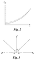
- Figure 2 shows the relationship between the driving current supplied to a pressure control valve of the system of Figure 1 and the pressure drop it produces,
- Figure 3 shows the desired relationship between the lateral acceleration of the vehicle and the pressure applied to the roll control actuators in the system of Figure 1, and
- Figure 4 shows the functional operation of part of the control unit of the system of Figure 1.
-
- Referring to Figure 1, a vehicle 1 has an active roll control system comprising a
front roll bar 2 and a rear roll bar 3, each divided into twoparts hydraulic actuator 4 to provide active roll control of the vehicle. Eachactuator 4 comprises a double acting ram having workingchambers 5, 6 on opposite sides of a piston 7 which are connected to ahydraulic control circuit 10 so that the pressures in them can be controlled to produce roll control moments in the front andrear roll bars 2, 3. - The hydraulic control circuit comprises a
pump 12 for supplying hydraulic fluid under pressure from areservoir 14, and avalve block 16 for controlling the distribution of hydraulic fluid to theactuators 4 and the return of fluid to thereservoir 14. The valve block has afirst port 18 for receiving pressurised fluid from thepump 12 into apressure line 18a in the block, and asecond drain port 20 for the return of fluid to thereservoir 14 from areturn line 20a in the block. The pressure andreturn lines diverter valve 22 which can allow fluid to flow from thepressure line 18a to thereturn line 20a to control the pressure drop between the pressure andreturn lines further solenoid valves valve block 16 which can selectively connect the pressure andreturn lines working chambers 5, 6 of each of thehydraulic actuators 4 to control the roll moments produced. - A
pressure transducer 28 produces a pressure signal indicative of the hydraulic pressure in thepressure line 18a, and acontrol unit 30 controls thevalves control unit 30 also receives signals fromaccelerometers 32 on the vehicle which indicate the lateral acceleration of the vehicle, and determines from these the pressure which needs to be applied across theactuators 4 to control the vehicle roll. - The
pressure control valve 22 is biased open, and is closed for brief periods by a pulse width modulated (PWM) drive signal, the duty ratio of the PWM signal determining the proportion of the time that the valve is closed, and hence the rate at which fluid can flow through it. This therefore determines the pressure drop across thevalve 22. - In Figure 2, the pressure drop P across the
pressure control valve 22 is shown as a function of mean drive current supplied to the pressure control valve. Since thevalve 22 is biased open, zero current corresponds to the valve being permanently open. However, because the hydraulic fluid has a finite viscosity, there will always be a finite minimum pressure drop across thevalve 22 when it is fully and permanently open. This minimum pressure drop is indicated in Figure 2 by the point at which the curve meets the vertical pressure axis. Because the viscosity of the hydraulic fluid decreases with increasing temperature, the minimum pressure drop also varies with temperature. In Figure 2, the solid line shows the oil pressure at relatively high temperatures, such as those experienced during normal running of the system, and the broken line shows pressures at a lower temperature such as might be experienced when the vehicle is first started up. - Referring to Figure 3, the desired pressure drop across the
valve 22, i.e. the desired pressure P to be applied across theroll control actuators 4 varies in a known manner with lateral acceleration A of the vehicle, depending on the roll control characteristics required. Ideally the pressure would be infinitely variable from zero up to the maximum available from thepump 12. However, because of the minimum pressure drop across thepressure control valve 22, pressures below the minimum pressure P0 cannot be applied. Thecontrol unit 30 is therefore arranged to apply no pressure across theactuators 4, and therefore to provide no active roll control, until the lateral acceleration reaches a threshold level At i.e. until the desired roll compensation moment reaches the minimum level which can be provided. This leaves a deadband of lateral acceleration, and a corresponding deadband of roll control moment, in which no active roll control can be provided. - Therefore, in order to improve the responsiveness of the system, the
control unit 30 is arranged to monitor the temperature of the valve block to determine the minimum pressure which can be applied to theactuators 4, so that it can provide roll control right down to the minimum possible level. The manner in which the temperature monitoring is carried out will now be described. - Referring to Figure 4, the control unit can be considered as a number of functional blocks. A
pressure control block 34 receives a signal Pd indicative of the desired pressure drop between thepressure line 18a and thereturn line 20a, and another signal V(P) which is the output signal from thepressure transducer 28. From the difference between the measured pressure and the desired pressure it produces a signal I which indicates the mean current which needs to be supplied to the solenoid 22a of thediverter valve 22 to produce the desired pressure at thefirst port 18. - A
current control block 36 receives the signal I and also has inputs connected to a battery voltage Vbat. It applies the battery voltage across the solenoid 22a as a pulsed signal, monitors the driving current flowing through the solenoid as a result, and modulates the pulse width so as to produce the total current corresponding to the signal I from the pressure control block. The current control block sends a signal M/S back to the pressure control block indicative of the mark to space (or duty) ratio of the driving current. - Because the electrical resistance of the solenoid 22a is temperature dependent, the duty ratio of the solenoid driving current required to produce a given mean current varies with the temperature of the solenoid. Therefore, because the valve block is a good thermal conductor, and the temperature of the hydraulic fluid passing through the
pressure control valve 22 will always be approximately equal to that of the solenoid 22a, thepressure control block 36 can determine the temperature of the hydraulic fluid from the relationship between the signal I and the signal M/S. - It will be appreciated that, as an alternative to the temperature measurement method described above, a separate thermometer could be provided for determining the temperature of the hydraulic fluid.
Claims (4)
- A vehicle suspension system comprising a hydraulic actuator (4), a source of hydraulic pressure (12) and a drain (20), a pressure control valve (22) for controlling the flow of hydraulic fluid from the source to the drain thereby to control the hydraulic pressure drop between the source and the drain, at least one actuation control valve (24, 26) for connecting the actuator between the source and the drain such that said pressure drop controls the magnitude of an actuating force produced by the actuator, and control means (30) arranged to operate the valves in response to at least one input defining a desired actuating force, characterized in that the control means (30) is arranged to connect the actuator (4) only when the desired actuating force is greater than a minimum value corresponding to a minimum pressure drop P0 which can be produced by the pressure control valve, and to determine the minimum pressure drop from measurement of the temperature of the hydraulic fluid.
- A system according to claim 1 wherein the control means (30) is arranged to obtain the measurement of said temperature by monitoring a temperature dependent characteristic of the drive current by which it controls at least one of the valves (22, 24, 26).
- A system according to claim 2 wherein said at least one of the valves is the pressure control valve (22).
- A system according to any foregoing claim wherein the actuator (4) is a roll control actuator arranged to control roll of a vehicle and the value of the minimum actuating force defines a deadband of low lateral accelerations for which roll control cannot be provided.
Applications Claiming Priority (2)
| Application Number | Priority Date | Filing Date | Title |
|---|---|---|---|
| GBGB9812274.0A GB9812274D0 (en) | 1998-06-09 | 1998-06-09 | Hydraulic control systems |
| GB9812274 | 1998-06-09 |
Publications (2)
| Publication Number | Publication Date |
|---|---|
| EP0963868A1 EP0963868A1 (en) | 1999-12-15 |
| EP0963868B1 true EP0963868B1 (en) | 2002-11-27 |
Family
ID=10833368
Family Applications (1)
| Application Number | Title | Priority Date | Filing Date |
|---|---|---|---|
| EP99304126A Expired - Lifetime EP0963868B1 (en) | 1998-06-09 | 1999-05-27 | Hydraulic control systems |
Country Status (4)
| Country | Link |
|---|---|
| US (1) | US6206383B1 (en) |
| EP (1) | EP0963868B1 (en) |
| DE (1) | DE69904112T2 (en) |
| GB (1) | GB9812274D0 (en) |
Families Citing this family (51)
| Publication number | Priority date | Publication date | Assignee | Title |
|---|---|---|---|---|
| EP1103396B1 (en) * | 1999-11-26 | 2009-04-22 | Delphi Technologies, Inc. | Vehicle roll control system |
| US6834218B2 (en) | 2001-11-05 | 2004-12-21 | Ford Global Technologies, Llc | Roll over stability control for an automotive vehicle |
| US7132937B2 (en) * | 2000-09-25 | 2006-11-07 | Ford Global Technologies, Llc | Wheel lift identification for an automotive vehicle using passive and active detection |
| US6904350B2 (en) | 2000-09-25 | 2005-06-07 | Ford Global Technologies, Llc | System for dynamically determining the wheel grounding and wheel lifting conditions and their applications in roll stability control |
| US6356188B1 (en) | 2000-09-25 | 2002-03-12 | Ford Global Technologies, Inc. | Wheel lift identification for an automotive vehicle |
| US7109856B2 (en) * | 2000-09-25 | 2006-09-19 | Ford Global Technologies, Llc | Wheel lifted and grounded identification for an automotive vehicle |
| US7233236B2 (en) * | 2000-09-25 | 2007-06-19 | Ford Global Technologies, Llc | Passive wheel lift identification for an automotive vehicle using operating input torque to wheel |
| DE10111551A1 (en) * | 2001-03-10 | 2002-09-12 | Bayerische Motoren Werke Ag | Active chassis system of a vehicle |
| US6654674B2 (en) * | 2001-11-21 | 2003-11-25 | Ford Global Technologies, Llc | Enhanced system for yaw stability control system to include roll stability control function |
| JP3951728B2 (en) * | 2002-02-06 | 2007-08-01 | トヨタ自動車株式会社 | Stabilizer device |
| US6556908B1 (en) | 2002-03-04 | 2003-04-29 | Ford Global Technologies, Inc. | Attitude sensing system for an automotive vehicle relative to the road |
| GB2388086B (en) * | 2002-05-02 | 2005-06-15 | Delphi Tech Inc | Vehicle roll control system |
| US7302331B2 (en) * | 2002-08-01 | 2007-11-27 | Ford Global Technologies, Inc. | Wheel lift identification for an automotive vehicle |
| US6941205B2 (en) * | 2002-08-01 | 2005-09-06 | Ford Global Technologies, Llc. | System and method for deteching roll rate sensor fault |
| US7194351B2 (en) * | 2002-08-01 | 2007-03-20 | Ford Global Technologies, Llc | System and method for determining a wheel departure angle for a rollover control system |
| US7003389B2 (en) | 2002-08-01 | 2006-02-21 | Ford Global Technologies, Llc | System and method for characterizing vehicle body to road angle for vehicle roll stability control |
| US7085639B2 (en) * | 2002-08-01 | 2006-08-01 | Ford Global Technologies, Llc | System and method for characterizing the road bank for vehicle roll stability control |
| US7079928B2 (en) * | 2002-08-01 | 2006-07-18 | Ford Global Technologies, Llc | System and method for determining a wheel departure angle for a rollover control system with respect to road roll rate and loading misalignment |
| US20040024505A1 (en) * | 2002-08-05 | 2004-02-05 | Salib Albert Chenouda | System and method for operating a rollover control system in a transition to a rollover condition |
| US6961648B2 (en) | 2002-08-05 | 2005-11-01 | Ford Motor Company | System and method for desensitizing the activation criteria of a rollover control system |
| US6963797B2 (en) * | 2002-08-05 | 2005-11-08 | Ford Global Technologies, Llc | System and method for determining an amount of control for operating a rollover control system |
| US20040024504A1 (en) * | 2002-08-05 | 2004-02-05 | Salib Albert Chenouda | System and method for operating a rollover control system during an elevated condition |
| US7430468B2 (en) * | 2002-08-05 | 2008-09-30 | Ford Global Technologies, Llc | System and method for sensitizing the activation criteria of a rollover control system |
| US7085642B2 (en) * | 2002-08-05 | 2006-08-01 | Ford Global Technologies, Llc | Method and system for correcting sensor offsets |
| US7653471B2 (en) * | 2003-02-26 | 2010-01-26 | Ford Global Technologies, Llc | Active driven wheel lift identification for an automotive vehicle |
| US9162656B2 (en) * | 2003-02-26 | 2015-10-20 | Ford Global Technologies, Llc | Active driven wheel lift identification for an automotive vehicle |
| US7239949B2 (en) * | 2003-02-26 | 2007-07-03 | Ford Global Technologies, Llc | Integrated sensing system |
| JP4155066B2 (en) * | 2003-03-12 | 2008-09-24 | トヨタ自動車株式会社 | Vehicle suspension system |
| JP3901190B2 (en) * | 2003-03-12 | 2007-04-04 | トヨタ自動車株式会社 | Vehicle suspension system |
| DE10314251A1 (en) * | 2003-03-29 | 2004-10-21 | Daimlerchrysler Ag | chassis control |
| US7136731B2 (en) * | 2003-06-11 | 2006-11-14 | Ford Global Technologies, Llc | System for determining vehicular relative roll angle during a potential rollover event |
| DE20313104U1 (en) | 2003-08-25 | 2004-01-15 | Trw Fahrwerksysteme Gmbh & Co Kg | Assembly for a chassis stabilization system |
| US7308350B2 (en) * | 2004-05-20 | 2007-12-11 | Ford Global Technologies, Llc | Method and apparatus for determining adaptive brake gain parameters for use in a safety system of an automotive vehicle |
| DE102004025807B4 (en) * | 2004-05-24 | 2009-01-22 | Zf Friedrichshafen Ag | Stabilizer arrangement for a motor vehicle |
| US7451032B2 (en) * | 2004-06-02 | 2008-11-11 | Ford Global Technologies, Llc | System and method for determining desired yaw rate and lateral velocity for use in a vehicle dynamic control system |
| US7475895B2 (en) * | 2004-06-15 | 2009-01-13 | Delphi Technologies, Inc. | Hydraulic circuit for a stabilizer bar |
| US7640081B2 (en) * | 2004-10-01 | 2009-12-29 | Ford Global Technologies, Llc | Roll stability control using four-wheel drive |
| US7715965B2 (en) * | 2004-10-15 | 2010-05-11 | Ford Global Technologies | System and method for qualitatively determining vehicle loading conditions |
| US7668645B2 (en) | 2004-10-15 | 2010-02-23 | Ford Global Technologies | System and method for dynamically determining vehicle loading and vertical loading distance for use in a vehicle dynamic control system |
| US7660654B2 (en) | 2004-12-13 | 2010-02-09 | Ford Global Technologies, Llc | System for dynamically determining vehicle rear/trunk loading for use in a vehicle control system |
| US7480547B2 (en) | 2005-04-14 | 2009-01-20 | Ford Global Technologies, Llc | Attitude sensing system for an automotive vehicle relative to the road |
| US7487973B1 (en) | 2005-08-24 | 2009-02-10 | Kelsey-Hayes Company | Multi-channel hydraulic control unit for an active vehicle suspension |
| US7590481B2 (en) * | 2005-09-19 | 2009-09-15 | Ford Global Technologies, Llc | Integrated vehicle control system using dynamically determined vehicle conditions |
| US8121758B2 (en) * | 2005-11-09 | 2012-02-21 | Ford Global Technologies | System for determining torque and tire forces using integrated sensing system |
| US7600826B2 (en) * | 2005-11-09 | 2009-10-13 | Ford Global Technologies, Llc | System for dynamically determining axle loadings of a moving vehicle using integrated sensing system and its application in vehicle dynamics controls |
| GB0618333D0 (en) * | 2006-09-19 | 2006-10-25 | Delphi Tech Inc | Hydraulic control circuit |
| GB0714102D0 (en) * | 2007-07-19 | 2007-08-29 | Delphi Tech Inc | Vehicle roll control |
| CN104129248B (en) * | 2014-08-11 | 2016-07-06 | 连云港天明装备有限公司 | Explosion-proof vehicle hydraulic damping device |
| FR3046571B1 (en) * | 2016-01-11 | 2018-01-26 | Peugeot Citroen Automobiles Sa | DEVICE FOR MANAGING THE ROLL ON A PENDULAR MOTOR VEHICLE |
| JP7147528B2 (en) * | 2018-12-11 | 2022-10-05 | トヨタ自動車株式会社 | Stabilizer device and stabilizer system including the same |
| DE102023115399B4 (en) * | 2023-06-13 | 2026-03-19 | Dr. Ing. H.C. F. Porsche Aktiengesellschaft | Method for operating a damping system of a vehicle |
Family Cites Families (24)
| Publication number | Priority date | Publication date | Assignee | Title |
|---|---|---|---|---|
| US4205864A (en) | 1978-10-12 | 1980-06-03 | Caterpillar Tractor Co. | Controlled demand priority hydraulic circuit |
| GB2223718B (en) * | 1988-09-22 | 1992-08-26 | Speechbond Limited | Control arrangement |
| JPH07102768B2 (en) | 1989-04-14 | 1995-11-08 | トヨタ自動車株式会社 | Fluid pressure active suspension |
| JP2502369B2 (en) | 1989-04-20 | 1996-05-29 | 日産自動車株式会社 | Solenoid drive device and active suspension control device using the same |
| JPH0314712A (en) | 1989-06-09 | 1991-01-23 | Toyota Motor Corp | Hydraulic suspension |
| JPH0331015A (en) | 1989-06-29 | 1991-02-08 | Toyota Motor Corp | Fluid pressure type active suspension |
| JP2509338B2 (en) | 1989-07-11 | 1996-06-19 | 日産自動車株式会社 | Active suspension |
| US5219181A (en) * | 1989-08-23 | 1993-06-15 | Tlc Suspension | Anti-roll system with tilt limitation |
| US5020826A (en) * | 1989-11-06 | 1991-06-04 | Southwest Research Institute | Vehicle suspension system |
| US5199854A (en) | 1990-08-08 | 1993-04-06 | Nissan Motor Co., Ltd. | Hydraulic supply arrangement for use with active automotive suspension or the like |
| US5161822A (en) * | 1990-11-26 | 1992-11-10 | Tlc Suspension | Tilt correction system |
| US5116069A (en) * | 1991-03-11 | 1992-05-26 | Miller Robert H | Three-wheel vehicle |
| JPH05254323A (en) | 1991-04-26 | 1993-10-05 | Aisin Seiki Co Ltd | Suspension device |
| IT1245804B (en) | 1991-05-06 | 1994-10-18 | Fiat Auto Spa | SYSTEM FOR THE CONTROL OF THE LOAD OF AN ANTI-ROLL STABILIZER BAR ASSOCIATED WITH A SUSPENSION WITH INDEPENDENT WHEELS OF A VEHICLE. |
| US5362094A (en) * | 1993-06-09 | 1994-11-08 | General Motors Corporation | Hydraulically controlled stabilizer bar system |
| JPH07228118A (en) | 1994-02-15 | 1995-08-29 | Aisin Seiki Co Ltd | Fluid pressure active suspension |
| US5443283A (en) * | 1994-03-07 | 1995-08-22 | Consol Inc. | Suspension system |
| US5597180A (en) | 1994-08-15 | 1997-01-28 | Ganzel; Blaise J. | Vehicle roll control apparatus |
| US5630623A (en) * | 1994-08-15 | 1997-05-20 | Kelsey Hayes | Vehicle roll control system |
| US5529324A (en) | 1994-08-15 | 1996-06-25 | Kelsey-Hayes Company | System and method for vehicle roll control |
| US5579229A (en) | 1995-03-27 | 1996-11-26 | General Motors Corporation | Temperature responsive suspension system control |
| GB2304652B (en) | 1995-08-24 | 1999-08-18 | Delphi France Automotive Sys | Vehicle roll control system |
| JPH10119529A (en) | 1996-10-18 | 1998-05-12 | Tokico Ltd | Suspension control device |
| GB9626045D0 (en) | 1996-12-14 | 1997-01-29 | Rover Group | A vehicle roll stabilising system |
-
1998
- 1998-06-09 GB GBGB9812274.0A patent/GB9812274D0/en not_active Ceased
-
1999
- 1999-05-26 US US09/320,066 patent/US6206383B1/en not_active Expired - Lifetime
- 1999-05-27 EP EP99304126A patent/EP0963868B1/en not_active Expired - Lifetime
- 1999-05-27 DE DE69904112T patent/DE69904112T2/en not_active Expired - Lifetime
Also Published As
| Publication number | Publication date |
|---|---|
| GB9812274D0 (en) | 1998-08-05 |
| US6206383B1 (en) | 2001-03-27 |
| EP0963868A1 (en) | 1999-12-15 |
| DE69904112T2 (en) | 2003-10-09 |
| DE69904112D1 (en) | 2003-01-09 |
Similar Documents
| Publication | Publication Date | Title |
|---|---|---|
| US6206383B1 (en) | Hydraulic control systems | |
| EP0462589B1 (en) | Control system for load sensing hydraulic drive circuit | |
| JP4653091B2 (en) | Control apparatus and method for supplying pressure means to at least two fluid pressure consumers | |
| US6019437A (en) | Vehicle hydraulic braking systems incorporating micro-machined technology | |
| KR101595116B1 (en) | Hydraulic system having multiple actuators and an associated control method | |
| US6164068A (en) | Variable pressure hydraulic systems | |
| US7200993B2 (en) | Electro-hydraulic steering control system | |
| KR101859631B1 (en) | Pressure compensated hydraulic system having differential pressure control | |
| KR100469548B1 (en) | Hydraulic emergency controller with control valve for continuously variable transmission | |
| US7059127B2 (en) | Hydro-pneumatic spring support arrangement | |
| KR100577833B1 (en) | Vehicle motion control and / or adjustment methods and systems | |
| US20070074510A1 (en) | Hydraulic system having augmented pressure compensation | |
| JP2008521692A (en) | Active chassis stabilization system | |
| EP3747716A1 (en) | Pneumatic vehicle axle brake assembly | |
| US6074019A (en) | Vehicle hydraulic braking systems of the brake-by-wire type | |
| EP0973667B1 (en) | Hydraulic steering arrangement | |
| GB2338460A (en) | Hydraulic control systems | |
| EP0964166B1 (en) | Hydraulic control systems | |
| JP3659654B2 (en) | Hydraulic circuit for construction machinery | |
| JP2622401B2 (en) | Hydraulic flow control device | |
| KR20070083958A (en) | Automotive Power Steering | |
| JPH08268256A (en) | Brake control device | |
| EP1657476B1 (en) | System for the control of the tractive force of a vehicle | |
| GB2160682A (en) | Control unit for an automotive vehicle | |
| JP3412643B2 (en) | Automotive steering control device |
Legal Events
| Date | Code | Title | Description |
|---|---|---|---|
| PUAI | Public reference made under article 153(3) epc to a published international application that has entered the european phase |
Free format text: ORIGINAL CODE: 0009012 |
|
| AK | Designated contracting states |
Kind code of ref document: A1 Designated state(s): DE ES FR IT SE Kind code of ref document: A1 Designated state(s): DE FR |
|
| AX | Request for extension of the european patent |
Free format text: AL;LT;LV;MK;RO;SI |
|
| 17P | Request for examination filed |
Effective date: 20000513 |
|
| AKX | Designation fees paid |
Free format text: DE ES FR IT SE |
|
| RAP1 | Party data changed (applicant data changed or rights of an application transferred) |
Owner name: LAND ROVER GROUP LIMITED |
|
| GRAG | Despatch of communication of intention to grant |
Free format text: ORIGINAL CODE: EPIDOS AGRA |
|
| 17Q | First examination report despatched |
Effective date: 20020403 |
|
| GRAG | Despatch of communication of intention to grant |
Free format text: ORIGINAL CODE: EPIDOS AGRA |
|
| GRAG | Despatch of communication of intention to grant |
Free format text: ORIGINAL CODE: EPIDOS AGRA |
|
| GRAH | Despatch of communication of intention to grant a patent |
Free format text: ORIGINAL CODE: EPIDOS IGRA |
|
| RBV | Designated contracting states (corrected) |
Designated state(s): DE FR |
|
| GRAH | Despatch of communication of intention to grant a patent |
Free format text: ORIGINAL CODE: EPIDOS IGRA |
|
| GRAA | (expected) grant |
Free format text: ORIGINAL CODE: 0009210 |
|
| AK | Designated contracting states |
Kind code of ref document: B1 Designated state(s): DE FR |
|
| REF | Corresponds to: |
Ref document number: 69904112 Country of ref document: DE Date of ref document: 20030109 |
|
| ET | Fr: translation filed | ||
| PLBE | No opposition filed within time limit |
Free format text: ORIGINAL CODE: 0009261 |
|
| STAA | Information on the status of an ep patent application or granted ep patent |
Free format text: STATUS: NO OPPOSITION FILED WITHIN TIME LIMIT |
|
| 26N | No opposition filed |
Effective date: 20030828 |
|
| REG | Reference to a national code |
Ref country code: FR Ref legal event code: TP |
|
| REG | Reference to a national code |
Ref country code: FR Ref legal event code: PLFP Year of fee payment: 18 |
|
| REG | Reference to a national code |
Ref country code: FR Ref legal event code: PLFP Year of fee payment: 19 |
|
| REG | Reference to a national code |
Ref country code: DE Ref legal event code: R082 Ref document number: 69904112 Country of ref document: DE |
|
| REG | Reference to a national code |
Ref country code: FR Ref legal event code: PLFP Year of fee payment: 20 |
|
| PGFP | Annual fee paid to national office [announced via postgrant information from national office to epo] |
Ref country code: DE Payment date: 20180419 Year of fee payment: 20 |
|
| PGFP | Annual fee paid to national office [announced via postgrant information from national office to epo] |
Ref country code: FR Payment date: 20180423 Year of fee payment: 20 |
|
| REG | Reference to a national code |
Ref country code: DE Ref legal event code: R071 Ref document number: 69904112 Country of ref document: DE |