EP0962823A1 - Apparatus and method for drying photosensitive material using radiant heat and air flow passages - Google Patents
Apparatus and method for drying photosensitive material using radiant heat and air flow passages Download PDFInfo
- Publication number
- EP0962823A1 EP0962823A1 EP99201620A EP99201620A EP0962823A1 EP 0962823 A1 EP0962823 A1 EP 0962823A1 EP 99201620 A EP99201620 A EP 99201620A EP 99201620 A EP99201620 A EP 99201620A EP 0962823 A1 EP0962823 A1 EP 0962823A1
- Authority
- EP
- European Patent Office
- Prior art keywords
- photosensitive material
- air
- drying
- processed
- air flow
- Prior art date
- Legal status (The legal status is an assumption and is not a legal conclusion. Google has not performed a legal analysis and makes no representation as to the accuracy of the status listed.)
- Withdrawn
Links
- 239000000463 material Substances 0.000 title claims abstract description 143
- 238000001035 drying Methods 0.000 title claims abstract description 73
- 238000000034 method Methods 0.000 title claims abstract description 15
- 238000010438 heat treatment Methods 0.000 claims abstract description 48
- 239000000839 emulsion Substances 0.000 abstract description 8
- 230000000694 effects Effects 0.000 abstract description 2
- 239000011248 coating agent Substances 0.000 description 8
- 238000000576 coating method Methods 0.000 description 8
- 230000001681 protective effect Effects 0.000 description 2
- 239000000853 adhesive Substances 0.000 description 1
- 230000001070 adhesive effect Effects 0.000 description 1
- 230000004888 barrier function Effects 0.000 description 1
- 230000009286 beneficial effect Effects 0.000 description 1
- 239000007844 bleaching agent Substances 0.000 description 1
- 238000001816 cooling Methods 0.000 description 1
- 230000003247 decreasing effect Effects 0.000 description 1
- 230000009977 dual effect Effects 0.000 description 1
- 239000003973 paint Substances 0.000 description 1
- 239000003381 stabilizer Substances 0.000 description 1
- 239000000126 substance Substances 0.000 description 1
- 238000011144 upstream manufacturing Methods 0.000 description 1
- 238000005406 washing Methods 0.000 description 1
Images

Classifications
-
- G—PHYSICS
- G03—PHOTOGRAPHY; CINEMATOGRAPHY; ANALOGOUS TECHNIQUES USING WAVES OTHER THAN OPTICAL WAVES; ELECTROGRAPHY; HOLOGRAPHY
- G03D—APPARATUS FOR PROCESSING EXPOSED PHOTOGRAPHIC MATERIALS; ACCESSORIES THEREFOR
- G03D15/00—Apparatus for treating processed material
- G03D15/02—Drying; Glazing
- G03D15/022—Drying of filmstrips
Definitions
- the present invention relates to the field of photoprocessing, and more particularly, to an apparatus and method for drying photosensitive material.
- the photosensitive material When drying photosensitive material such as processed photosensitive material, photographic prints, cut sheets or film, the photosensitive material is traditionally conveyed through a dryer by way of guides and/or rollers which contact the photosensitive material. During drying of the photosensitive material it is beneficial that drying occurs in a rapid manner and that any contact on the emulsion side of the photosensitive material be minimized. By minimizing contact between the emulsion side of the photosensitive material and the guides and/or rollers, distortions or damage to the photosensitive materials decreased.
- U.S. Patent No. 3,973,328 discloses the application of radiant heat on both sides of a photographic sheet to dry the photographic sheet.
- U.S. Patent No. 3,973,328 further shows the application of an air flow to the paper path.
- the air flow in U.S. Patent No. 3,973,328 is a cool air flow which is maintained between 20°C and 40°C and assists in cooling down rollers located on each side of a radiant heating bar arrangement.
- U.S. Patent No. 4,257,172 discloses a radiant heating bar arrangement which includes ventilating passages.
- the dryer of U.S. Patent No.4,257,172 is primarily for removing vaporous substances such as paints, adhesives, and moisture from a product.
- the use of the ventilating passages is to remove a vapor barrier.
- the present invention relates to an apparatus and method for drying photosensitive material which utilizes the combination of radiant heat and forced air.
- radiant heating bars partially surrounded by reflective covers direct heat onto photosensitive material to dry the photosensitive material.
- air is supplied through passages which are defined between the reflective covers onto the photosensitive material. This air is heated by heat from the heating bars which radiate through the reflective covers, and the heated air impinges upon the photosensitive material so as to increase the drying of the photosensitive material and at the same time hold the photosensitive material firmly against drive rollers within the drying apparatus.
- One application of the present invention is to dry photosensitive material such as processed photosensitive material which has had a viscous solution of predetermined viscosity applied thereon; as shown in, for example, co-pending applications USSN 08/965,560, USSN 08/965,639 and USSN 08/965,105, the subject matter of which is herein incorporated by reference.
- a processed photosensitive material includes a solution of a predetermined viscosity applied thereon which forms a protective overcoat over the photosensitive material.
- the system and apparatus of the present invention permits such a drying by using radiant heating bars on one side of the photosensitive material to dry the photosensitive material, and at the same time, impinging the photosensitive material with air that is heated by radiant heat from the heating bars to increase drying of the photosensitive material, and hold the photosensitive material firmly against drive rollers.
- the present invention is not limited to drying processed photosensitive material and/or processed photosensitive material having a viscous solution applied thereon as described above, and is also applicable to drying cut sheets, webs or any type of product which is desired to be dried in a manner which does not disturb the product or the surface of the product.
- the present invention relates to an apparatus for drying photosensitive material which comprises a plurality of radiant heating bars for applying radiant heat to photosensitive material to dry the photosensitive material.
- Each of the radiant heating bars is partially surrounded by a cover member.
- air flow passages are defined between the cover members for the passage of the air therethrough, with the air passing through the air flow passages being directed onto the photosensitive material and being heated by heat from the heating bars which radiates through the cover members. The heated air is impinged onto the photosensitive material to increase drying of the photosensitive material.
- the present invention also relates to a method of drying photosensitive material which comprises the step of applying radiant heat by way of radiant heating bars to photosensitive material to dry the photosensitive material.
- the heating bars are each partially surrounded by cover members, wherein an air flow passage is defined between each of the cover members.
- the method of the present invention comprises the further step of directing air through each of the air flow passages such that the air is heated by heat from the heating bars which radiates through the cover members, with the heated air being impinged onto the photosensitive material to increase drying of the photosensitive material.
- the present invention also relates to a photoprocessing system which comprises a photoprocessing assembly for processing photosensitive material; and a drying apparatus for drying the processed photosensitive material.
- the drying apparatus comprises a plurality of radiant heating bars for applying radiant heat to the processed photosensitive material to dry the processed photosensitive material, with each of the radiant heating bars being partially surrounded by a cover member.
- Air flow passages are defined between the cover members for the passage of air therethrough. The air passing through the air flow passages is directed onto the processed photosensitive material and is heated by heat from the heating bars which radiates through the cover members, such that the heated air is impinged onto the processed photosensitive material to increase drying of the processed photosensitive material.
- the present invention further relates to a photoprocessing method which comprises the steps of processing a photosensitive material; applying radiant heat by way of radiant heating bars to the processed photosensitive material to dry the processed photosensitive material, with the radiant heating bars being partially surrounded by cover members, wherein an air flow passage is defined between each of said cover members; and directing air trough each of the air flow passages such that the air is heated by heat from the heating bars which radiates through the cover members, with the heated air being impinged onto the processed photosensitive material to increase drying of the processed photosensitive material.
- apparatus 5 for drying photosensitive material is shown.
- apparatus 5 is positioned downstream of, for example, a coating apparatus (not shown) and a metering roller 7, with respect to a photosensitive material conveying direction 50.
- apparatus 5 dries photosensitive material 9 onto which has been applied a solution of predetermined viscosity which forms a protective overcoat, (see applications USSN 08/965,560, USSN 08/965,639 and USSN 08/965,105). That is, after photosensitive material 9 has been coated with a viscous solution, the applied solution is metered by way of metering rollers 7 and lead to drying apparatus 5.
- drying apparatus 5 is not limited to drying photosensitive material having a viscous solution applied thereon, and is also not limited to being utilized downstream of a coating apparatus or metering roller. Drying apparatus 5 is appliable to dry any type of photosensitive material, photographic print, cut web or sheet, or any type of paper product in which drying is desired. Drying apparatus 5 can also be positioned at various locations of a processing system in which drying is desired.
- drying apparatus 5 includes radiant heating bars 11 which are located on one side and above photosensitive material 9. Radiant heating bars 11 extend transversely with respect to conveying direction 50 and can be set up as an array of sequential radiant heating bars as illustrated in Figure 1. Additionally, a cover 14 such as a reflective cover or shroud partially surrounds radiant heating bars 11 so as to assist in directing radiant heat onto a top side or emulsion side 9a of photosensitive material 9. Cover 14 includes a plurality of cover members 14a which each surround a corresponding radiant heating bar 11.
- photosensitive material 9 As illustrated in Figure 1, as photosensitive material 9 enters drying apparatus 5 at entrance 30a, it is conveyed through drying apparatus 5 in direction 50. Photosensitive material 9 is transported by way of drive rollers 15 which support the bottom of photosensitive material 9 as it is conveyed through drying apparatus 5. Within drying apparatus 5, a heating chamber 19 is defined between the top or emulsion side 9a of photosensitive material 9 and openings 21 of cover members 14a. Accordingly, radiant heat from radiant heating bars 11 is directed onto photosensitive material 9 as photosensitive material 9 passes below radiant heating bars 11 to dry photosensitive material 9.
- cover 14 comprises a plenum in the form of inwardly tapering air passages 23 that extend between each of cover members 14a.
- air can be supplied by way of, for example, an air blower (not shown) into each of air passages 23 as illustrated by arrows 25.
- an air blower not shown
- the air is heated to a temperature preferably within a range of 150°F to 200°F by heat from heating bars 11 which radiates through cover members 14a.
- the heated air passes through air passages 23 which inwardly taper and expands as the air enters heating chamber 19 as illustrated by arrows 25a.
- the present invention can incorporate a known auxiliary heating source to increase the temperature of the air prior to entering the drying apparatus.
- photosensitive material 9 After photosensitive material 9 is dried, it can be conveyed through an exit 30b of drying apparatus 5 by way of, for example, drive rollers 29.
- the heated air which exits air passages 23 is applied to photosensitive material 9 with a force that is sufficient enough to firmly hold photosensitive material 9 against drive rollers 15. This assures that photosensitive material 9 is maintained flat without requiring the use of rollers or guides which tend to touch the emulsion side of the photosensitive material 9. Thus, damage or distortion of photosensitive material 9 is minimized.
- the heated air which passes through air passages 23 serves the dual purpose of increasing the drying effect of drying apparatus 5 and holding photosensitive material 9 firmly flat against drive rollers 15.
- air passages 23 can be located such that they are positioned over a corresponding drive roller 15 as shown.
- each of air passages 23 extend transversely with respect to conveying direction 50, and drying apparatus 5 includes an air cavity entry port 40 in communication with each air passage 23.
- each air passage 23 is sloped or inclined in a downward direction from air cavity entry port 40. With this arrangement, air which exits air passage 23 at a downstream area 21a will have a force which is substantially equal to air which exits air passage 23 at an upstream area 21b. This assures that the air will impinge onto photosensitive material 9 with a substantially equal force along the width of photosensitive material 9 so as to eliminate any uneven drying.
- FIG 3 schematically illustrates an example of a photoprocessing system to which drying apparatus 5 of the present invention can be applied.
- drying apparatus 5 (the details of which are shown and described above with reference to Figures 1 and 2) can be placed downstream of a processing assembly 60.
- Processing assembly 60 can be a known arrangement which includes tanks that respectively contain developer solution, bleach solution, fixer solution and washing solution; or a combination of bleach-fix solution and a wash/stabilizer solution.
- Each of the tanks of processing assembly 60 represent steps in the developing process of photosensitive material.
- after processed photosensitive material leaves processing assembly 60 it is conveyed through path 63a into drying apparatus 5 where it is dried as described above with reference to Figures 1 and 2.
- a coating apparatus 65 such as described in, for example, copending applications USSN 08/965,560, USSN 08/965,639 and USSN 08/965,105, can be located in between processing assembly 60 and drying apparatus 5. That is, coating apparatus 65 can be placed in path 63a between processing assembly 60 and drying apparatus 5, so that the processed photosensitive material exiting processing assembly 60 is coated with a solution at coating apparatus 65 and then conveyed to drying apparatus 5. Drying apparatus 5 of the present invention is effective to dry processed photosensitive material having a viscous solution applied thereon.
- coating apparatus 65 can be placed in a bypass line 63b between processing assembly 60 and drying apparatus 5.
- diverters 67,68 are operable in a first mode to bypass coating apparatus 65 and lead the processed photosensitive material via path 63a to drying apparatus 5, and operable in a second mode to lead the processed photosensitive material to coating apparatus 65 via line 63b, and thereafter to drying apparatus 5.
- the present invention provides for an arrangement which permits rapid drying of photosensitive material, such as processed photosensitive material having a solution of predetermined viscosity applied thereon, photographic prints, cut sheets, webs, etc.
- the drying apparatus of the present invention includes heating bars on one side of the photosensitive materials and drive rollers on an opposite side of the photosensitive material which provides for a compact arrangement. Additionally, the arrangement of the present invention permits a rapid drying without the necessity of emulsion side contact.
Landscapes
- Physics & Mathematics (AREA)
- General Physics & Mathematics (AREA)
- Drying Of Solid Materials (AREA)
- Photographic Processing Devices Using Wet Methods (AREA)
- Photosensitive Polymer And Photoresist Processing (AREA)
Abstract
A drying apparatus and method utilizes radiant heat and forced air
to provide for rapid drying of photosensitive material without emulsion side
contact. The forced air is supplied through air passages formed between cover
members that partially surround radiant heating bars, and is directed onto the
photosensitive material where it impinges upon the photosensitive material. As
the air passes through the air passages, it is heated by radiant heat from the heating
bars. The heated air increases the drying effect of the drying apparatus and at the
same time, impinges on the photosensitive material in a manner which assists in
holding the photosensitive material firmly against, for example, drive rollers.
Description
- The present invention relates to the field of photoprocessing, and more particularly, to an apparatus and method for drying photosensitive material.
- When drying photosensitive material such as processed photosensitive material, photographic prints, cut sheets or film, the photosensitive material is traditionally conveyed through a dryer by way of guides and/or rollers which contact the photosensitive material. During drying of the photosensitive material it is beneficial that drying occurs in a rapid manner and that any contact on the emulsion side of the photosensitive material be minimized. By minimizing contact between the emulsion side of the photosensitive material and the guides and/or rollers, distortions or damage to the photosensitive materials decreased.
- U.S. Patent No. 3,973,328 discloses the application of radiant heat on both sides of a photographic sheet to dry the photographic sheet. U.S. Patent No. 3,973,328 further shows the application of an air flow to the paper path. The air flow in U.S. Patent No. 3,973,328 is a cool air flow which is maintained between 20°C and 40°C and assists in cooling down rollers located on each side of a radiant heating bar arrangement.
- U.S. Patent No. 4,257,172 discloses a radiant heating bar arrangement which includes ventilating passages. The dryer of U.S. Patent No.4,257,172 is primarily for removing vaporous substances such as paints, adhesives, and moisture from a product. In this document, the use of the ventilating passages is to remove a vapor barrier.
- The present invention relates to an apparatus and method for drying photosensitive material which utilizes the combination of radiant heat and forced air. In the present invention, radiant heating bars partially surrounded by reflective covers direct heat onto photosensitive material to dry the photosensitive material. Additionally, air is supplied through passages which are defined between the reflective covers onto the photosensitive material. This air is heated by heat from the heating bars which radiate through the reflective covers, and the heated air impinges upon the photosensitive material so as to increase the drying of the photosensitive material and at the same time hold the photosensitive material firmly against drive rollers within the drying apparatus.
- One application of the present invention is to dry photosensitive material such as processed photosensitive material which has had a viscous solution of predetermined viscosity applied thereon; as shown in, for example, co-pending applications USSN 08/965,560, USSN 08/965,639 and USSN 08/965,105, the subject matter of which is herein incorporated by reference. In this situation, a processed photosensitive material includes a solution of a predetermined viscosity applied thereon which forms a protective overcoat over the photosensitive material. During the drying of such a photosensitive material, it is important that the photosensitive material with the solution applied thereon be dried in a manner which does not disturb the applied solution. The system and apparatus of the present invention permits such a drying by using radiant heating bars on one side of the photosensitive material to dry the photosensitive material, and at the same time, impinging the photosensitive material with air that is heated by radiant heat from the heating bars to increase drying of the photosensitive material, and hold the photosensitive material firmly against drive rollers. Of course, the present invention is not limited to drying processed photosensitive material and/or processed photosensitive material having a viscous solution applied thereon as described above, and is also applicable to drying cut sheets, webs or any type of product which is desired to be dried in a manner which does not disturb the product or the surface of the product.
- The present invention relates to an apparatus for drying photosensitive material which comprises a plurality of radiant heating bars for applying radiant heat to photosensitive material to dry the photosensitive material. Each of the radiant heating bars is partially surrounded by a cover member. In the apparatus of the present invention, air flow passages are defined between the cover members for the passage of the air therethrough, with the air passing through the air flow passages being directed onto the photosensitive material and being heated by heat from the heating bars which radiates through the cover members. The heated air is impinged onto the photosensitive material to increase drying of the photosensitive material.
- The present invention also relates to a method of drying photosensitive material which comprises the step of applying radiant heat by way of radiant heating bars to photosensitive material to dry the photosensitive material. The heating bars are each partially surrounded by cover members, wherein an air flow passage is defined between each of the cover members. The method of the present invention comprises the further step of directing air through each of the air flow passages such that the air is heated by heat from the heating bars which radiates through the cover members, with the heated air being impinged onto the photosensitive material to increase drying of the photosensitive material.
- The present invention also relates to a photoprocessing system which comprises a photoprocessing assembly for processing photosensitive material; and a drying apparatus for drying the processed photosensitive material. The drying apparatus comprises a plurality of radiant heating bars for applying radiant heat to the processed photosensitive material to dry the processed photosensitive material, with each of the radiant heating bars being partially surrounded by a cover member. Air flow passages are defined between the cover members for the passage of air therethrough. The air passing through the air flow passages is directed onto the processed photosensitive material and is heated by heat from the heating bars which radiates through the cover members, such that the heated air is impinged onto the processed photosensitive material to increase drying of the processed photosensitive material.
- The present invention further relates to a photoprocessing method which comprises the steps of processing a photosensitive material; applying radiant heat by way of radiant heating bars to the processed photosensitive material to dry the processed photosensitive material, with the radiant heating bars being partially surrounded by cover members, wherein an air flow passage is defined between each of said cover members; and directing air trough each of the air flow passages such that the air is heated by heat from the heating bars which radiates through the cover members, with the heated air being impinged onto the processed photosensitive material to increase drying of the processed photosensitive material.
-
- Figure 1 is a schematic illustration of a drying apparatus in accordance with the present invention;
- Figure 2 is a sectional view along line II-II of Figure 1; and
- Figure 3 is a schematic illustration of a photoprocessing system in accordance with the present invention.
-
- Referring now to Figure 1, an
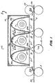
apparatus 5 for drying photosensitive material is shown. In the embodiment as illustrated in Figure 1,apparatus 5 is positioned downstream of, for example, a coating apparatus (not shown) and a metering roller 7, with respect to a photosensitivematerial conveying direction 50. When utilized in this manner,apparatus 5 driesphotosensitive material 9 onto which has been applied a solution of predetermined viscosity which forms a protective overcoat, (see applications USSN 08/965,560, USSN 08/965,639 and USSN 08/965,105). That is, afterphotosensitive material 9 has been coated with a viscous solution, the applied solution is metered by way of metering rollers 7 and lead to dryingapparatus 5. This is just one example for using dryingapparatus 5 of the present invention It is recognized that dryingapparatus 5 is not limited to drying photosensitive material having a viscous solution applied thereon, and is also not limited to being utilized downstream of a coating apparatus or metering roller.Drying apparatus 5 is appliable to dry any type of photosensitive material, photographic print, cut web or sheet, or any type of paper product in which drying is desired.Drying apparatus 5 can also be positioned at various locations of a processing system in which drying is desired. - As illustrated in Figure 1,
drying apparatus 5 includes radiant heating bars 11 which are located on one side and abovephotosensitive material 9. Radiant heating bars 11 extend transversely with respect to conveyingdirection 50 and can be set up as an array of sequential radiant heating bars as illustrated in Figure 1. Additionally, acover 14 such as a reflective cover or shroud partially surrounds radiant heating bars 11 so as to assist in directing radiant heat onto a top side oremulsion side 9a ofphotosensitive material 9.Cover 14 includes a plurality ofcover members 14a which each surround a corresponding radiant heating bar 11. - Thus, as illustrated in Figure 1, as
photosensitive material 9 enters dryingapparatus 5 atentrance 30a, it is conveyed through dryingapparatus 5 indirection 50.Photosensitive material 9 is transported by way ofdrive rollers 15 which support the bottom ofphotosensitive material 9 as it is conveyed through dryingapparatus 5. Within dryingapparatus 5, aheating chamber 19 is defined between the top oremulsion side 9a ofphotosensitive material 9 andopenings 21 ofcover members 14a. Accordingly, radiant heat from radiant heating bars 11 is directed ontophotosensitive material 9 asphotosensitive material 9 passes below radiant heating bars 11 to dryphotosensitive material 9. - As further illustrated in Figure 1,
cover 14 comprises a plenum in the form of inwardly taperingair passages 23 that extend between each ofcover members 14a. With this arrangement, air can be supplied by way of, for example, an air blower (not shown) into each ofair passages 23 as illustrated byarrows 25. As the air passes through each ofair passages 23, the air is heated to a temperature preferably within a range of 150°F to 200°F by heat from heating bars 11 which radiates throughcover members 14a. The heated air passes throughair passages 23 which inwardly taper and expands as the air entersheating chamber 19 as illustrated byarrows 25a. As the air entersheating chamber 19, it is impinged or forced against top oremulsion surface 9a ofphotosensitive material 9 to further aid in drying of thephotosensitive material 9. It is further recognized that the present invention can incorporate a known auxiliary heating source to increase the temperature of the air prior to entering the drying apparatus. - After
photosensitive material 9 is dried, it can be conveyed through anexit 30b of dryingapparatus 5 by way of, for example,drive rollers 29. - Therefore, with the arrangement of the present invention, as
photosensitive material 9 is transported indirection 50 through dryingapparatus 5, radiant heat and forced heated air are alternatively and sequentially applied tosurface 9a ofphotosensitive material 9. - In a further feature of the present invention, the heated air which exits
air passages 23 is applied tophotosensitive material 9 with a force that is sufficient enough to firmly holdphotosensitive material 9 againstdrive rollers 15. This assures thatphotosensitive material 9 is maintained flat without requiring the use of rollers or guides which tend to touch the emulsion side of thephotosensitive material 9. Thus, damage or distortion ofphotosensitive material 9 is minimized. - Therefore, the heated air which passes through
air passages 23 serves the dual purpose of increasing the drying effect of dryingapparatus 5 and holdingphotosensitive material 9 firmly flat againstdrive rollers 15. As illustrated in Figure 1, in order to enhance the ability of the forced air to holdphotosensitive material 9 againstdrive rollers 15,air passages 23 can be located such that they are positioned over acorresponding drive roller 15 as shown. - Also, as shown in Figure 2, each of
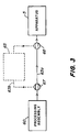
air passages 23 extend transversely with respect to conveyingdirection 50, and dryingapparatus 5 includes an aircavity entry port 40 in communication with eachair passage 23. As illustrated in Figure 2, eachair passage 23 is sloped or inclined in a downward direction from aircavity entry port 40. With this arrangement, air which exitsair passage 23 at a downstream area 21a will have a force which is substantially equal to air which exitsair passage 23 at an upstream area 21b. This assures that the air will impinge ontophotosensitive material 9 with a substantially equal force along the width ofphotosensitive material 9 so as to eliminate any uneven drying. - Figure 3 schematically illustrates an example of a photoprocessing system to which
drying apparatus 5 of the present invention can be applied. As shown in Figure 3, drying apparatus 5 (the details of which are shown and described above with reference to Figures 1 and 2) can be placed downstream of aprocessing assembly 60. Processingassembly 60 can be a known arrangement which includes tanks that respectively contain developer solution, bleach solution, fixer solution and washing solution; or a combination of bleach-fix solution and a wash/stabilizer solution. Each of the tanks ofprocessing assembly 60 represent steps in the developing process of photosensitive material. In one embodiment, after processed photosensitive materialleaves processing assembly 60, it is conveyed throughpath 63a into dryingapparatus 5 where it is dried as described above with reference to Figures 1 and 2. - In a further embodiment, a
coating apparatus 65, such as described in, for example, copending applications USSN 08/965,560, USSN 08/965,639 and USSN 08/965,105, can be located in betweenprocessing assembly 60 and dryingapparatus 5. That is,coating apparatus 65 can be placed inpath 63a betweenprocessing assembly 60 and dryingapparatus 5, so that the processed photosensitive material exitingprocessing assembly 60 is coated with a solution atcoating apparatus 65 and then conveyed to dryingapparatus 5.Drying apparatus 5 of the present invention is effective to dry processed photosensitive material having a viscous solution applied thereon. - As a further option and as shown in Figure 3,
coating apparatus 65 can be placed in abypass line 63b betweenprocessing assembly 60 and dryingapparatus 5. With this arrangement and through the use ofdiverters exits processing assembly 60,diverters coating apparatus 65 and lead the processed photosensitive material viapath 63a to dryingapparatus 5, and operable in a second mode to lead the processed photosensitive material tocoating apparatus 65 vialine 63b, and thereafter to dryingapparatus 5. - Accordingly, the present invention provides for an arrangement which permits rapid drying of photosensitive material, such as processed photosensitive material having a solution of predetermined viscosity applied thereon, photographic prints, cut sheets, webs, etc. The drying apparatus of the present invention includes heating bars on one side of the photosensitive materials and drive rollers on an opposite side of the photosensitive material which provides for a compact arrangement. Additionally, the arrangement of the present invention permits a rapid drying without the necessity of emulsion side contact.
Claims (16)
- An apparatus for drying photosensitive material, the apparatus comprising:a plurality of radiant heating bars for applying radiant heat to photosensitive material to dry the photosensitive material, each of said radiant heating bars being partially surrounded by a cover member;
wherein air flow passages are defined between said cover members for the passage of air therethrough, said air passing through said air flow passages being directed onto said photosensitive material and being heated by heat from said heating bars which radiates through said cover members, such that said heated air is impinged onto said photosensitive material to increase drying of said photosensitive material. - An apparatus according to claim 1, further comprising drive rollers for transporting the photosensitive material through said apparatus, wherein said heated air impinged on said photosensitive material holds said photosensitive material flat against said drive rollers.
- An apparatus according to claim 1, wherein said photosensitive material is a processed photosensitive material.
- An apparatus according to claim 1, wherein said photosensitive material is one of a photographic print, a cut sheet or a web.
- An apparatus according to claim 1, wherein each of said air flow passages inwardly taper in an air flow direction.
- An apparatus according to claim 2, wherein each of said air flow passages opens toward said photosensitive material at area above a corresponding one of said drive rollers.
- An apparatus according to claim 2, wherein said radiant heating bars, said cover members and said air flow passages are provided on one side of said photosensitive material, and said drive rollers are provided on an opposite side of said photosensitive material.
- An apparatus according to claim 1, wherein each of said air passages are inclined in a width-wise direction of said photosensitive material.
- A method of drying photosensitive material, the method comprising the steps of:applying radiant heat by way of radiant heating bars to photosensitive material to dry the photosensitive material, said radiant heating bars being partially surrounded by cover members, wherein an air flow passage is defined between each of said cover members; anddirecting air through each of said air flow passages such that said air is heated by heat from said heating bars which radiate through said cover members, said heated air being impinged onto said photosensitive material to increase drying of said photosensitive material.
- A method according to claim 9, comprising the further step of conveying said photosensitive material below said radiant heating bars and said air flow passages by way of drive rollers, wherein said heated air impinged onto said photosensitive material holds said photosensitive material against said drive rollers.
- A method according to claim 9, wherein said photosensitive material is a processed photosensitive material.
- A method according to claim 9, wherein said photosensitive material is one of a photographic print, cut sheet or web.
- A photoprocessing system comprising:a processing assembly for processing photosensitive material; anda drying apparatus for drying said processed photosensitive material, said drying apparatus comprising a plurality of radiant heating bars for applying radiant heat to said processed photosensitive material to dry said processed photosensitive material, each of said radiant heating bars being partially surrounded by a cover member;
wherein air flow passages are defined between said cover members for the passage of air therethrough, said air passing through said air flow passages being directed onto said processed photosensitive material and being heated by heat from said heating bars which radiates through said cover members, such that said heated air is impinged onto said processed photosensitive material to increase drying of said processed photosensitive material. - A photoprocessing system according to claim 13, wherein said drying apparatus further comprises drive rollers for transporting the processed photosensitive material through said drying apparatus, wherein said heated air impinged on said processed photosensitive material holds said processed photosensitive material flat against said drive rollers.
- A photoprocessing method comprising the steps of:processing a photosensitive material;applying radiant heat by way of radiant heating bars to said processed photosensitive material to dry said processed photosensitive material, said radiant heating bars being partially surrounded by cover members, wherein an air flow passage is defined between each of said cover members; anddirecting air through each of said air flow passages such that said air is heated by heat from said heating bars which radiate through said cover members, said heated air being impinged onto said processed photosensitive material to increase drying of said processed photosensitive material.
- A method according to claim 15, comprising the further step of conveying said processed photosensitive material below said radiant heating bars and said air flow passages by way of drive rollers, wherein said heated air impinged onto said processed photosensitive material holds said processed photosensitive material against said drive rollers.
Applications Claiming Priority (2)
| Application Number | Priority Date | Filing Date | Title |
|---|---|---|---|
| US92593 | 1998-06-05 | ||
| US09/092,593 US6058621A (en) | 1998-06-05 | 1998-06-05 | Apparatus and method for drying photosensitive material using radiant heat and air flow passages |
Publications (1)
| Publication Number | Publication Date |
|---|---|
| EP0962823A1 true EP0962823A1 (en) | 1999-12-08 |
Family
ID=22234016
Family Applications (1)
| Application Number | Title | Priority Date | Filing Date |
|---|---|---|---|
| EP99201620A Withdrawn EP0962823A1 (en) | 1998-06-05 | 1999-05-25 | Apparatus and method for drying photosensitive material using radiant heat and air flow passages |
Country Status (4)
| Country | Link |
|---|---|
| US (1) | US6058621A (en) |
| EP (1) | EP0962823A1 (en) |
| JP (1) | JP2000029192A (en) |
| CN (1) | CN1238474A (en) |
Families Citing this family (9)
| Publication number | Priority date | Publication date | Assignee | Title |
|---|---|---|---|---|
| DE20218908U1 (en) * | 2002-12-06 | 2003-02-13 | MAN Roland Druckmaschinen AG, 63075 Offenbach | Excimer heater for the dryer of a printing press |
| ATE388826T1 (en) * | 2005-12-22 | 2008-03-15 | Tapematic Spa | A DEVICE FOR DRYING BY RADIATION |
| US7966743B2 (en) * | 2007-07-31 | 2011-06-28 | Eastman Kodak Company | Micro-structured drying for inkjet printers |
| JP4790092B1 (en) * | 2010-04-30 | 2011-10-12 | 日本碍子株式会社 | Coating film drying furnace |
| US8465578B2 (en) | 2011-03-31 | 2013-06-18 | Eastman Kodak Company | Inkjet printing ink set |
| US8398223B2 (en) | 2011-03-31 | 2013-03-19 | Eastman Kodak Company | Inkjet printing process |
| US20130306271A1 (en) * | 2012-05-18 | 2013-11-21 | Shenzhen China Star Optoelectronics Technology Co., Ltd. | Blowing Device and Method for Using the Blowing Device |
| US9126434B2 (en) * | 2014-01-22 | 2015-09-08 | Ricoh Company, Ltd. | Radiant heat control with adjustable reflective element |
| US9427975B2 (en) | 2014-06-12 | 2016-08-30 | Eastman Kodak Company | Aqueous ink durability deposited on substrate |
Citations (3)
| Publication number | Priority date | Publication date | Assignee | Title |
|---|---|---|---|---|
| US3720002A (en) * | 1970-03-19 | 1973-03-13 | Wiggins Teape Res Dev | Drying sheet material |
| FR2184053A1 (en) * | 1972-05-10 | 1973-12-21 | Minnesota Mining & Mfg | |
| EP0068207A1 (en) * | 1981-06-19 | 1983-01-05 | Minnesota Mining And Manufacturing Company | Infrared drying device for water-impregnated photographic films |
Family Cites Families (12)
| Publication number | Priority date | Publication date | Assignee | Title |
|---|---|---|---|---|
| US3364062A (en) * | 1965-12-27 | 1968-01-16 | Rayonier Inc | Emulsion coating of cellulosic films |
| US3973328A (en) * | 1972-05-26 | 1976-08-10 | Ilford Limited | Paper material dryer |
| US3994073A (en) * | 1975-04-08 | 1976-11-30 | Ppg Industries, Inc. | Air cooling means for UV processor |
| GB1561897A (en) * | 1976-10-20 | 1980-03-05 | Ciba Geigy Ag | Photographic drying apparatus |
| US4257172A (en) * | 1979-01-22 | 1981-03-24 | Olympic Infra-Dry Inc. | Combination forced air and infrared dryer |
| DE3124688C2 (en) * | 1981-06-24 | 1983-12-08 | Agfa-Gevaert Ag, 5090 Leverkusen | Device for drying tape-shaped or sheet-shaped photographic substrates |
| US5323546A (en) * | 1989-02-10 | 1994-06-28 | Eastman Kodak Company | Method of drying photographic materials |
| JPH03132660A (en) * | 1989-10-19 | 1991-06-06 | Fuji Photo Film Co Ltd | Photosensitive material dryer |
| US5070627A (en) * | 1990-01-16 | 1991-12-10 | W. R. Grace & Co.-Conn. | Directional diffusion nozzle air bar |
| FR2710971B1 (en) * | 1993-10-06 | 1995-12-29 | Infra Rouge System | Non-contact deflection device for sheet material. |
| JP2914557B2 (en) * | 1994-09-13 | 1999-07-05 | ノーリツ鋼機株式会社 | Photosensitive material drying equipment |
| US5756294A (en) * | 1995-09-25 | 1998-05-26 | Oncormed, Inc. | Susceptibility mutation for breast and ovarian cancer |
-
1998
- 1998-06-05 US US09/092,593 patent/US6058621A/en not_active Expired - Fee Related
-
1999
- 1999-05-25 EP EP99201620A patent/EP0962823A1/en not_active Withdrawn
- 1999-06-01 JP JP11153684A patent/JP2000029192A/en active Pending
- 1999-06-04 CN CN99107166.2A patent/CN1238474A/en active Pending
Patent Citations (3)
| Publication number | Priority date | Publication date | Assignee | Title |
|---|---|---|---|---|
| US3720002A (en) * | 1970-03-19 | 1973-03-13 | Wiggins Teape Res Dev | Drying sheet material |
| FR2184053A1 (en) * | 1972-05-10 | 1973-12-21 | Minnesota Mining & Mfg | |
| EP0068207A1 (en) * | 1981-06-19 | 1983-01-05 | Minnesota Mining And Manufacturing Company | Infrared drying device for water-impregnated photographic films |
Also Published As
| Publication number | Publication date |
|---|---|
| JP2000029192A (en) | 2000-01-28 |
| CN1238474A (en) | 1999-12-15 |
| US6058621A (en) | 2000-05-09 |
Similar Documents
| Publication | Publication Date | Title |
|---|---|---|
| US6058621A (en) | Apparatus and method for drying photosensitive material using radiant heat and air flow passages | |
| US7073274B2 (en) | Drying device | |
| JP3445316B2 (en) | Film transfer device | |
| US6092303A (en) | Apparatus and method for drying photosensitive material using radiant section and an air flow section | |
| JP2002287317A (en) | Drying equipment | |
| JP2003215776A (en) | Drying equipment | |
| US5568693A (en) | Method and an apparatus for the processing of photographic sheet material | |
| US6401360B1 (en) | Apparatus and method for drying photosensitive material using a radiant heat assembly | |
| US7077584B2 (en) | Dryer for a recording medium | |
| JPH0350259B2 (en) | ||
| JP2804775B2 (en) | Drying control method for photographic processing equipment | |
| US6979802B2 (en) | Apparatus and method for thermally processing an imaging material employing a preheat chamber | |
| US6751889B2 (en) | Photographic media dryer | |
| JP3781226B2 (en) | Heating device | |
| KR100338741B1 (en) | Sheet feeding apparatus for printing device | |
| JPH0237578B2 (en) | ||
| US3744148A (en) | Drying apparatus for photographic sheet material | |
| JP2942669B2 (en) | Drying device for automatic processor | |
| JP2551618B2 (en) | Drying device for developing device | |
| JPH08262685A (en) | Photo sheet processing equipment | |
| JPS61153653A (en) | Drying device of sheet | |
| JPH0869093A (en) | Processing method of photographic photosensitive material | |
| EP0699958A1 (en) | A method and apparatus for the processing of photographic sheet material | |
| JPH0772607A (en) | Photosensitive material processing equipment | |
| JPH0450969A (en) | Photosensitive material processing device |
Legal Events
| Date | Code | Title | Description |
|---|---|---|---|
| PUAI | Public reference made under article 153(3) epc to a published international application that has entered the european phase |
Free format text: ORIGINAL CODE: 0009012 |
|
| AK | Designated contracting states |
Kind code of ref document: A1 Designated state(s): DE FR GB |
|
| AX | Request for extension of the european patent |
Free format text: AL;LT;LV;MK;RO;SI |
|
| 17P | Request for examination filed |
Effective date: 20000508 |
|
| AKX | Designation fees paid |
Free format text: DE FR GB |
|
| 17Q | First examination report despatched |
Effective date: 20030805 |
|
| STAA | Information on the status of an ep patent application or granted ep patent |
Free format text: STATUS: THE APPLICATION IS DEEMED TO BE WITHDRAWN |
|
| 18D | Application deemed to be withdrawn |
Effective date: 20031216 |