EP0962343B1 - Compact trailer refrigeration unit - Google Patents
Compact trailer refrigeration unit Download PDFInfo
- Publication number
- EP0962343B1 EP0962343B1 EP99302476A EP99302476A EP0962343B1 EP 0962343 B1 EP0962343 B1 EP 0962343B1 EP 99302476 A EP99302476 A EP 99302476A EP 99302476 A EP99302476 A EP 99302476A EP 0962343 B1 EP0962343 B1 EP 0962343B1
- Authority
- EP
- European Patent Office
- Prior art keywords
- heat exchanger
- condenser
- evaporator
- fans
- unit
- Prior art date
- Legal status (The legal status is an assumption and is not a legal conclusion. Google has not performed a legal analysis and makes no representation as to the accuracy of the status listed.)
- Expired - Lifetime
Links
Images


Classifications
-
- B—PERFORMING OPERATIONS; TRANSPORTING
- B60—VEHICLES IN GENERAL
- B60H—ARRANGEMENTS OF HEATING, COOLING, VENTILATING OR OTHER AIR-TREATING DEVICES SPECIALLY ADAPTED FOR PASSENGER OR GOODS SPACES OF VEHICLES
- B60H1/00—Heating, cooling or ventilating devices
- B60H1/00421—Driving arrangements for parts of a vehicle air-conditioning
- B60H1/00428—Driving arrangements for parts of a vehicle air-conditioning electric
-
- B—PERFORMING OPERATIONS; TRANSPORTING
- B60—VEHICLES IN GENERAL
- B60H—ARRANGEMENTS OF HEATING, COOLING, VENTILATING OR OTHER AIR-TREATING DEVICES SPECIALLY ADAPTED FOR PASSENGER OR GOODS SPACES OF VEHICLES
- B60H1/00—Heating, cooling or ventilating devices
- B60H1/32—Cooling devices
- B60H1/3204—Cooling devices using compression
- B60H1/3226—Self-contained devices, i.e. including own drive motor
-
- B—PERFORMING OPERATIONS; TRANSPORTING
- B60—VEHICLES IN GENERAL
- B60H—ARRANGEMENTS OF HEATING, COOLING, VENTILATING OR OTHER AIR-TREATING DEVICES SPECIALLY ADAPTED FOR PASSENGER OR GOODS SPACES OF VEHICLES
- B60H1/00—Heating, cooling or ventilating devices
- B60H1/32—Cooling devices
- B60H1/3204—Cooling devices using compression
- B60H1/3232—Cooling devices using compression particularly adapted for load transporting vehicles
-
- F—MECHANICAL ENGINEERING; LIGHTING; HEATING; WEAPONS; BLASTING
- F25—REFRIGERATION OR COOLING; COMBINED HEATING AND REFRIGERATION SYSTEMS; HEAT PUMP SYSTEMS; MANUFACTURE OR STORAGE OF ICE; LIQUEFACTION SOLIDIFICATION OF GASES
- F25D—REFRIGERATORS; COLD ROOMS; ICE-BOXES; COOLING OR FREEZING APPARATUS NOT OTHERWISE PROVIDED FOR
- F25D17/00—Arrangements for circulating cooling fluids; Arrangements for circulating gas, e.g. air, within refrigerated spaces
- F25D17/04—Arrangements for circulating cooling fluids; Arrangements for circulating gas, e.g. air, within refrigerated spaces for circulating air, e.g. by convection
- F25D17/06—Arrangements for circulating cooling fluids; Arrangements for circulating gas, e.g. air, within refrigerated spaces for circulating air, e.g. by convection by forced circulation
- F25D17/067—Evaporator fan units
-
- F—MECHANICAL ENGINEERING; LIGHTING; HEATING; WEAPONS; BLASTING
- F25—REFRIGERATION OR COOLING; COMBINED HEATING AND REFRIGERATION SYSTEMS; HEAT PUMP SYSTEMS; MANUFACTURE OR STORAGE OF ICE; LIQUEFACTION SOLIDIFICATION OF GASES
- F25D—REFRIGERATORS; COLD ROOMS; ICE-BOXES; COOLING OR FREEZING APPARATUS NOT OTHERWISE PROVIDED FOR
- F25D19/00—Arrangement or mounting of refrigeration units with respect to devices or objects to be refrigerated, e.g. infrared detectors
- F25D19/003—Arrangement or mounting of refrigeration units with respect to devices or objects to be refrigerated, e.g. infrared detectors with respect to movable containers
-
- F—MECHANICAL ENGINEERING; LIGHTING; HEATING; WEAPONS; BLASTING
- F25—REFRIGERATION OR COOLING; COMBINED HEATING AND REFRIGERATION SYSTEMS; HEAT PUMP SYSTEMS; MANUFACTURE OR STORAGE OF ICE; LIQUEFACTION SOLIDIFICATION OF GASES
- F25D—REFRIGERATORS; COLD ROOMS; ICE-BOXES; COOLING OR FREEZING APPARATUS NOT OTHERWISE PROVIDED FOR
- F25D2317/00—Details or arrangements for circulating cooling fluids; Details or arrangements for circulating gas, e.g. air, within refrigerated spaces, not provided for in other groups of this subclass
- F25D2317/06—Details or arrangements for circulating cooling fluids; Details or arrangements for circulating gas, e.g. air, within refrigerated spaces, not provided for in other groups of this subclass with forced air circulation
- F25D2317/068—Details or arrangements for circulating cooling fluids; Details or arrangements for circulating gas, e.g. air, within refrigerated spaces, not provided for in other groups of this subclass with forced air circulation characterised by the fans
- F25D2317/0681—Details thereof
-
- F—MECHANICAL ENGINEERING; LIGHTING; HEATING; WEAPONS; BLASTING
- F25—REFRIGERATION OR COOLING; COMBINED HEATING AND REFRIGERATION SYSTEMS; HEAT PUMP SYSTEMS; MANUFACTURE OR STORAGE OF ICE; LIQUEFACTION SOLIDIFICATION OF GASES
- F25D—REFRIGERATORS; COLD ROOMS; ICE-BOXES; COOLING OR FREEZING APPARATUS NOT OTHERWISE PROVIDED FOR
- F25D2317/00—Details or arrangements for circulating cooling fluids; Details or arrangements for circulating gas, e.g. air, within refrigerated spaces, not provided for in other groups of this subclass
- F25D2317/06—Details or arrangements for circulating cooling fluids; Details or arrangements for circulating gas, e.g. air, within refrigerated spaces, not provided for in other groups of this subclass with forced air circulation
- F25D2317/068—Details or arrangements for circulating cooling fluids; Details or arrangements for circulating gas, e.g. air, within refrigerated spaces, not provided for in other groups of this subclass with forced air circulation characterised by the fans
- F25D2317/0683—Details or arrangements for circulating cooling fluids; Details or arrangements for circulating gas, e.g. air, within refrigerated spaces, not provided for in other groups of this subclass with forced air circulation characterised by the fans the fans not of the axial type
-
- Y—GENERAL TAGGING OF NEW TECHNOLOGICAL DEVELOPMENTS; GENERAL TAGGING OF CROSS-SECTIONAL TECHNOLOGIES SPANNING OVER SEVERAL SECTIONS OF THE IPC; TECHNICAL SUBJECTS COVERED BY FORMER USPC CROSS-REFERENCE ART COLLECTIONS [XRACs] AND DIGESTS
- Y02—TECHNOLOGIES OR APPLICATIONS FOR MITIGATION OR ADAPTATION AGAINST CLIMATE CHANGE
- Y02T—CLIMATE CHANGE MITIGATION TECHNOLOGIES RELATED TO TRANSPORTATION
- Y02T10/00—Road transport of goods or passengers
- Y02T10/80—Technologies aiming to reduce greenhouse gasses emissions common to all road transportation technologies
- Y02T10/88—Optimized components or subsystems, e.g. lighting, actively controlled glasses
Definitions
- This invention relates to a transport refrigeration system and, in particular, to an all electric compact trailer refrigeration unit that receives its electrical power from a single on board diesel engine and electric generator combination.
- Trailer refrigeration units are know in the art utilizing electrically regulated power sources necessary to operate on board electrical components.
- such units include small generators that are well suited to powering a limited group of devices.
- these conventional refrigeration units are not capable of producing sufficient power to simultaneously operate all of the unit components requiring a power input.
- Such units require engine driven compressors in combination with a generator to produce the power, or alternatively some other type of auxiliary power.
- These prior art units also rely upon mechanical connections between the prime mover and the driven components.
- the compressor shaft is directly coupled to the prime mover and thereby necessitates complex shaft seals to prevent refrigerant from leaking from the compressor.
- These mechanical couplings and complex seals are not only costly, but are difficult to install and maintain.
- US patent no. 5,123,258 discloses a replacement rear door for a van comprising in combination an interior front panel, an exterior rear panel with exterior peripheral panels defining an internal equipment storage zone; an air conditioning system housed entirely within the equipment storage zone for cooling the warm air generated in the passenger section of the van; a gasoline powered internal combustion engine for generating the power to operate the air conditioning system; gasoline connection means adapted to be coupled into the main gasoline supply line for supplying fuel to the engine; electric connection means adapted to couple the main battery of the van to the peripheral equipment of the engine; electronic means for controlling the stopping and starting of the air conditioning system; and hinge means extending outwardly from one of the exterior side panels for mating with the body hinges on the van.
- a still further object of the present invention is to provide a compact trailer refrigeration unit having enlarged heat exchanger surfaces for providing a high rate of heat rejection and improve the ability to cool under high ambient temperatures.
- Another object of the present invention is to provide a trailer refrigeration unit wherein the condenser fan, the evaporator fan and the compressor are all powered by an electrical generator driven by a prime mover such as a diesel engine.
- Yet another object of the present invention is to eliminate the need for mechanical coupling between the prime mover of a trailer refrigeration unit and the power driven components of the unit.
- Still another object of the present invention is to utilize multiple fans in association with the heat exchangers of a trailer refrigeration system to increase the airflow through the system while at the same time conserving space and increasing the amount of heat rejected by the heat exchangers.
- Yet a further object of the present invention is to utilize the airflow passing through the condenser unit of a trailer refrigeration system to provide cooling to the prime mover and the compressor of the unit.
- a still further object of the present invention is to utilize multiple fans for servicing the evaporator heat exchanger of a trailer refrigeration unit which allow for the use of a larger heat exchanger surface area and which further enhance the distribution of conditioned air throughout the trailer cargo container.
- a trailer refrigeration unit that includes a support frame that is mountable upon the front wall of a trailer cargo container.
- the frame has an upper section and a lower section.
- a prime mover such as a diesel engine is housed in the lower section of the frame and is connected in combination with electrical generators to form a power package.
- An electrically powered compressor is also mounted in the lower section of the frame and is driven by power supplied by the generator.
- the upper section of the support frame contains a front compartment and a rear compartment that are separated by a common wall.
- a condenser heat exchanger is mounted in the front compartment of the upper section of the frame and an evaporator heat exchanger is mounted in the rear compartment behind the condenser heat exchanger.
- a pair of electrically driven vane axial fans are mounted in the bottom of the front compartment within an air passage located behind the condenser heat exchanger.
- the condenser fans are arranged to draw a high volume of air through the condenser heat exchanger and pass air over both the power package and the compressor situated below the fans in the lower section of the frame.
- a pair of centrifugal fans are mounted in the top of the rear compartment and are arranged to draw return air from the cargo container through the evaporator heat exchanger and return conditioned supply air to the cargo container.
- the evaporator fans are arranged to turn in opposite directions to conduct conditioned supply air along the center of the cargo container along the ceiling to cool both the walls of the container and the cargo before being returned to the inlet of the evaporator heat exchanger.
- An evaporator air passage is situated behind the evaporator heat exchanger and is separated from the condenser air passage by the common wall.
- the commonly shared wall is inclined with regard to the vertical centerline of the frame so that the flow passages behind each heat exchanger diverges in the direction of air flow.
- This package results in a truck trailer refrigeration unit that is extremely compact and devoid of constraints imposed by conventional belt drives, shafts and other types of mechanical linkages.
- the permanent magnet generator 13 can be either a synchronous or non-synchronous type and the refrigeration unit electronic controls can be customized to provide a match between the generator output and refrigeration unit components powered thereby.
- An electrical control box 15 furnishes a compact singular interface between the various electrically driven components coupled to the power package.
- the truck trailer refrigeration unit 10 further includes a compressor 17 mounted above and to one side of the diesel engine and generator power package within a mounting bracket 18.
- the mounting bracket 18 forms part of the main support frame 19 of the refrigeration unit which is secured to the front wall of the cargo container 20.
- the mounting bracket 18 is located in the lower section of the support frame 19.
- the upper section of the support frame contains back to back compartments 21 and 22 (Fig. 3) that are separated by a wall 23.
- the front compartment 21 houses the condenser heat exchanger 24 of the refrigeration unit while the rear compartment 22 houses the unit's evaporator heat exchanger 25.
- a condenser air passage 26 is provided behind the condenser heat exchanger in the front compartment and an evaporator air passage 27 is provided behind the evaporator heat exchanger in the rear compartment.
- the two back-to-back air passages are separated by the common wall 23.
- the condenser is connected to the discharge port of the refrigerant compressor and the evaporator is similarly connected to the suction port of the compressor.
- the two heat exchangers are, in turn, connected together by a refrigerant line 28 (Fig. 3) containing an expansion device 29 to complete the refrigeration circuit.
- the condenser heat exchanger contains an enlarged surface area 23 (Fig. 2) which faces the front of the truck.
- the large surface area serves to minimize the pressure drop over the condenser and allow for a high rate of airflow through the unit.
- a pair of electrically driven vane axial fan units 30 are mounted in the bottom wall of the front compartment 21 and are arranged to draw ambient air through the condenser heat exchanger as indicated by the arrows in Fig. 3.
- the condenser air passage 26 diverges in the direction of air flow from the top of the front compartment toward the bottom of the compartment.
- the passage and dual fan units are designed to accommodate a high rate of airflow through the condenser under high static loading.
- An electrical motor 32 is supported upon the stator blades 33 of each fan unit and the stator blades, in turn, are secured to the fan housing 35.
- the distance between the rotor blades 36 of each fan unit and the stator blades is more than one blade chord length.
- the rotor preferably contains between five and eleven blades each having a skewed geometry such that the tip sweep of each blade is between 50° and 70°.
- the stator preferably contains between eleven and twenty three blades that are skewed in a direction that is opposite to that of the rotor blades and having a sweep angle at the tip of each blade of between 20° and 50°. The rotor blades thus pass the stator blades at about 90° thus minimizing the interaction between the rotor and the stator and reducing the amount of noise produced by the fan.
- each condenser fan which as noted above, is supported on the stator blades and is largely contained within the hub 38 of the fan unit.
- the inlet bell 39 (Fig. 4) of each fan unit has an elliptical shape with its major axis being about 0.05 to 0.15 times the rotor diameter and its minor axis being about 0.03 to 0.10 times the rotor diameter. This construction further reduces the low noise level of the fan while considerably reducing the size of the units without sacrificing the rate of airflow through the condenser.
- centrifugal fan units may also be similarly employed. Again, the centrifugal units are mounted in the upper compartment and arranged to pass cooling air over the compressor and the motor-generator power package. Alternatively, the centrifugal units can be arranged to discharge the condenser air out of the sides of the refrigeration unit.
- the evaporator fans and the condenser fans each rotate in a horizontal plane and are placed above and below the evaporator and condenser heat exchangers. Accordingly, the fans do not block the air passages through the heat exchanger coils allowing a full volume of air to pass over the exchanger surfaces.
- the rear compartment 21 of the support frame contains a large rectangular shaped opening 40 that enters the back of the cargo container 20.
- the evaporator heat exchanger 25 is situated behind the opening and is placed at an incline with respect to the vertical center line of the refrigeration unit. This, in turn, allows for the use of a heat exchanger having an expanded surface area without the need for additional space.
- a pair of high performance, electrically driven centrifugal fan units 45 are mounted in the top part of the rear compartment and are arranged to draw a high volume of air from the cargo container through the evaporator heat exchanger.
- the conditioned air after passing through the heat exchanger, is conducted through the evaporator air passage 27, turned 90° in the fan units and returned to the cargo container through two exit openings 47 provided in the top of the container's front wall.
- the top openings in the container are located just below the container ceiling 48 (Fig. 3) so that conditioned supply air is directed along the ceiling toward the back of the container.
- the centrifugal fans are arranged to turn in opposite directions to further direct the supply airflow toward the center of the container. This, in turn, causes the conditioned supply to become well distributed over the walls of the container as well as the cargo to provide for highly efficient uniform temperature distribution throughout the container.
- each evaporator fan unit passes through the roof of the rear compartment and is secured to the unit support frame.
- the fan impeller 55 is attached to the motor housing 62 (Fig. 6).
- the motor In prior art, centrifugal fan units of this type, the motor generally blocks a significant amount of air at the inlet to the impeller. This results in an unwanted, generally, relatively large, pressure drop at the entrance to the fan forcing the fan to do additional work to overcome entrance losses. Entrance losses are considerably reduced in the present centrifugal units by providing each unit with a large rotating shroud 57 having a correspondingly large inlet orifice 56.
- the shroud and the orifice each has an elliptical shape which serves to more efficiently conduct air through the impeller with a minimal amount of flow separation.
- the leading edge of each impeller blade 60 also is furnished with an elliptical shape enabling the blades to quickly fill the gap between the motor housing 62 and the inlet orifice with the air resulting in improved performance at high static pressures.
- the cargo container as illustrated in Figs. 7a and 7b may be partitioned into separate zones by walls with one of the centrifugal fan units being arranged to service each of the zones. In this way, the temperature in each zone can be controlled by independently regulating the activity of each evaporator fan unit. As illustrated in Fig. 7a, the cargo container may be divided into two distinct zones 70 and 71 by means of a partition 72. Conditioned supply air to each zone is provided by one of the two evaporator fan units 45. Similarly, as illustrated in Fig.
- the present refrigeration unit may be altered to include a small auxiliary evaporator heat exchanger 74 having short refrigeration and condensate drain lines that are connected into the main unit and a separate small electrically driven centrifugal fan unit 75.
- the cargo container is divided into three zones by two partitions 76 and 77. These zones included two other zones 78 and 79 of substantially equal volume and an interior zone 80 of relatively less volume. The two outer zones in this case are serviced by fan units 45 and the interior zone is serviced by fan unit 75.
- the condenser fan units 30 that are mounted in the front compartment of the upper section of the support frame each contain an exit diffuser 82.
- the diffuser of the left hand fan unit is arranged to direct the exhaust air from the fan unit over the compressor 17.
- the exit diffuser of the right hand fan unit is arranged to direct exhaust air over the power package 14.
- the present refrigeration unit represents a very compact system that is ideally suited for use in servicing a truck trailer application. Beyond being compact, the present unit is entirely electrically driven, thus eliminating noisy and oftentimes troublesome mechanical drives such as belts, gears, and the like.
- the multiple condenser and evaporator fans provide for a wide flexibility in design and enhance the overall performance of the unit. The high airflow furnished by the fans and the large heat exchanger surface area further results in a high rate of heat rejection while at the same time conserving space, energy and fuel.
Landscapes
- Engineering & Computer Science (AREA)
- Physics & Mathematics (AREA)
- Thermal Sciences (AREA)
- Mechanical Engineering (AREA)
- Chemical & Material Sciences (AREA)
- Combustion & Propulsion (AREA)
- General Engineering & Computer Science (AREA)
- Devices That Are Associated With Refrigeration Equipment (AREA)
Abstract
Description
- This invention relates to a transport refrigeration system and, in particular, to an all electric compact trailer refrigeration unit that receives its electrical power from a single on board diesel engine and electric generator combination.
- Trailer refrigeration units are know in the art utilizing electrically regulated power sources necessary to operate on board electrical components. Typically, such units include small generators that are well suited to powering a limited group of devices. However, these conventional refrigeration units are not capable of producing sufficient power to simultaneously operate all of the unit components requiring a power input. Such units require engine driven compressors in combination with a generator to produce the power, or alternatively some other type of auxiliary power. These prior art units also rely upon mechanical connections between the prime mover and the driven components. Also, the compressor shaft is directly coupled to the prime mover and thereby necessitates complex shaft seals to prevent refrigerant from leaking from the compressor. These mechanical couplings and complex seals are not only costly, but are difficult to install and maintain.
- There still exists a need in the art for a truly compact, lightweight trailer refrigeration unit that does not have the problems associated with mechanical belts, pulleys, clutches and the like, and which is capable of delivery a high airflow rate and a high rate of heat rejection needed to meet the demands of present day cargo containers and trailers.
- US patent no. 5,123,258 discloses a replacement rear door for a van comprising in combination an interior front panel, an exterior rear panel with exterior peripheral panels defining an internal equipment storage zone; an air conditioning system housed entirely within the equipment storage zone for cooling the warm air generated in the passenger section of the van; a gasoline powered internal combustion engine for generating the power to operate the air conditioning system; gasoline connection means adapted to be coupled into the main gasoline supply line for supplying fuel to the engine; electric connection means adapted to couple the main battery of the van to the peripheral equipment of the engine; electronic means for controlling the stopping and starting of the air conditioning system; and hinge means extending outwardly from one of the exterior side panels for mating with the body hinges on the van.
- It is therefore an object of the present invention to improve refrigeration units and, in particular, refrigeration units employed in association with trailer cargo containers.
- It is a further object of the present invention to provide an extremely lightweight, compact trailer refrigeration unit having a high rate of airflow through the unit and a reduced level of noise.
- A still further object of the present invention is to provide a compact trailer refrigeration unit having enlarged heat exchanger surfaces for providing a high rate of heat rejection and improve the ability to cool under high ambient temperatures.
- Another object of the present invention is to provide a trailer refrigeration unit wherein the condenser fan, the evaporator fan and the compressor are all powered by an electrical generator driven by a prime mover such as a diesel engine.
- Yet another object of the present invention is to eliminate the need for mechanical coupling between the prime mover of a trailer refrigeration unit and the power driven components of the unit.
- Still another object of the present invention is to utilize multiple fans in association with the heat exchangers of a trailer refrigeration system to increase the airflow through the system while at the same time conserving space and increasing the amount of heat rejected by the heat exchangers.
- Yet a further object of the present invention is to utilize the airflow passing through the condenser unit of a trailer refrigeration system to provide cooling to the prime mover and the compressor of the unit.
- A still further object of the present invention is to utilize multiple fans for servicing the evaporator heat exchanger of a trailer refrigeration unit which allow for the use of a larger heat exchanger surface area and which further enhance the distribution of conditioned air throughout the trailer cargo container.
- These and other objects of the present invention are attained by means of a trailer refrigeration unit that includes a support frame that is mountable upon the front wall of a trailer cargo container. The frame has an upper section and a lower section. A prime mover such as a diesel engine is housed in the lower section of the frame and is connected in combination with electrical generators to form a power package. An electrically powered compressor is also mounted in the lower section of the frame and is driven by power supplied by the generator. The upper section of the support frame contains a front compartment and a rear compartment that are separated by a common wall. A condenser heat exchanger is mounted in the front compartment of the upper section of the frame and an evaporator heat exchanger is mounted in the rear compartment behind the condenser heat exchanger. A pair of electrically driven vane axial fans are mounted in the bottom of the front compartment within an air passage located behind the condenser heat exchanger. The condenser fans are arranged to draw a high volume of air through the condenser heat exchanger and pass air over both the power package and the compressor situated below the fans in the lower section of the frame. A pair of centrifugal fans are mounted in the top of the rear compartment and are arranged to draw return air from the cargo container through the evaporator heat exchanger and return conditioned supply air to the cargo container. The evaporator fans are arranged to turn in opposite directions to conduct conditioned supply air along the center of the cargo container along the ceiling to cool both the walls of the container and the cargo before being returned to the inlet of the evaporator heat exchanger. An evaporator air passage is situated behind the evaporator heat exchanger and is separated from the condenser air passage by the common wall. The commonly shared wall is inclined with regard to the vertical centerline of the frame so that the flow passages behind each heat exchanger diverges in the direction of air flow.
- For a better understanding of these and other objects of the present invention, reference will be made to the following detailed description of the invention which is to be read in association with the accompanying drawings, wherein:
- Fig. I is a partial view in perspective showing a truck trailer combination equipped with a refrigeration unit embodying the teachings of the present invention;
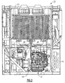
- Fig. 2 is a front elevation of the present refrigeration unit with the cover panels removed;
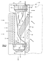
- Fig. 3 is a partial side elevation of the refrigeration unit showing the upper section of the support frame;
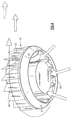
- Fig. 4 is an enlarged perspective view of one of the condenser fan units utilized in the refrigeration unit;
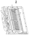
- Fig. 5 is a perspective view showing the rear wall of the upper section of the refrigeration unit;
- Fig. 6 is an enlarged view in perspective showing one of the evaporator fan units utilized in the refrigeration unit; and
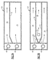
- Fig. 7a and Fig. 7b are schematic top views of a cargo container employing different cargo compartment configurations that are compatible with various evaporator fan arrangements.
-
- Referring initially to Figs. 1 and 2, there is illustrated a
tractor trailer 11 containing a refrigeration unit, generally referenced 10, that embodies the teachings of the present invention wherein the refrigeration unit derives its electrical power solely from adiesel engine 12 that is integrally joined with apermanent magnet generator 13 to form what herein will be referred to as apower package 14. This package results in a truck trailer refrigeration unit that is extremely compact and devoid of constraints imposed by conventional belt drives, shafts and other types of mechanical linkages. Thepermanent magnet generator 13 can be either a synchronous or non-synchronous type and the refrigeration unit electronic controls can be customized to provide a match between the generator output and refrigeration unit components powered thereby. Anelectrical control box 15 furnishes a compact singular interface between the various electrically driven components coupled to the power package. The trucktrailer refrigeration unit 10 further includes acompressor 17 mounted above and to one side of the diesel engine and generator power package within amounting bracket 18. Themounting bracket 18 forms part of the main support frame 19 of the refrigeration unit which is secured to the front wall of thecargo container 20. - The
mounting bracket 18 is located in the lower section of the support frame 19. The upper section of the support frame contains back toback compartments 21 and 22 (Fig. 3) that are separated by awall 23. Thefront compartment 21 houses thecondenser heat exchanger 24 of the refrigeration unit while therear compartment 22 houses the unit'sevaporator heat exchanger 25. Acondenser air passage 26 is provided behind the condenser heat exchanger in the front compartment and anevaporator air passage 27 is provided behind the evaporator heat exchanger in the rear compartment. The two back-to-back air passages are separated by thecommon wall 23. As is conventional in the art, the condenser is connected to the discharge port of the refrigerant compressor and the evaporator is similarly connected to the suction port of the compressor. The two heat exchangers are, in turn, connected together by a refrigerant line 28 (Fig. 3) containing anexpansion device 29 to complete the refrigeration circuit. - The condenser heat exchanger contains an enlarged surface area 23 (Fig. 2) which faces the front of the truck. The large surface area serves to minimize the pressure drop over the condenser and allow for a high rate of airflow through the unit.
- As best illustrated in Figs. 2-4, a pair of electrically driven vane
axial fan units 30 are mounted in the bottom wall of thefront compartment 21 and are arranged to draw ambient air through the condenser heat exchanger as indicated by the arrows in Fig. 3. Thecondenser air passage 26 diverges in the direction of air flow from the top of the front compartment toward the bottom of the compartment. The passage and dual fan units are designed to accommodate a high rate of airflow through the condenser under high static loading. Anelectrical motor 32 is supported upon thestator blades 33 of each fan unit and the stator blades, in turn, are secured to thefan housing 35. The distance between the rotor blades 36 of each fan unit and the stator blades is more than one blade chord length. The rotor preferably contains between five and eleven blades each having a skewed geometry such that the tip sweep of each blade is between 50° and 70°. The stator preferably contains between eleven and twenty three blades that are skewed in a direction that is opposite to that of the rotor blades and having a sweep angle at the tip of each blade of between 20° and 50°. The rotor blades thus pass the stator blades at about 90° thus minimizing the interaction between the rotor and the stator and reducing the amount of noise produced by the fan. - The motor of each condenser fan, which as noted above, is supported on the stator blades and is largely contained within the
hub 38 of the fan unit. The inlet bell 39 (Fig. 4) of each fan unit has an elliptical shape with its major axis being about 0.05 to 0.15 times the rotor diameter and its minor axis being about 0.03 to 0.10 times the rotor diameter. This construction further reduces the low noise level of the fan while considerably reducing the size of the units without sacrificing the rate of airflow through the condenser. - Although the condenser fans utilized in the practice of the present invention are preferably vane axial units, centrifugal fan units may also be similarly employed. Again, the centrifugal units are mounted in the upper compartment and arranged to pass cooling air over the compressor and the motor-generator power package. Alternatively, the centrifugal units can be arranged to discharge the condenser air out of the sides of the refrigeration unit.
- It should be noted that the evaporator fans and the condenser fans each rotate in a horizontal plane and are placed above and below the evaporator and condenser heat exchangers. Accordingly, the fans do not block the air passages through the heat exchanger coils allowing a full volume of air to pass over the exchanger surfaces.
- With further reference to Figs. 3 and 5, the
rear compartment 21 of the support frame contains a large rectangular shapedopening 40 that enters the back of thecargo container 20. Theevaporator heat exchanger 25 is situated behind the opening and is placed at an incline with respect to the vertical center line of the refrigeration unit. This, in turn, allows for the use of a heat exchanger having an expanded surface area without the need for additional space. A pair of high performance, electrically drivencentrifugal fan units 45 are mounted in the top part of the rear compartment and are arranged to draw a high volume of air from the cargo container through the evaporator heat exchanger. The conditioned air, after passing through the heat exchanger, is conducted through theevaporator air passage 27, turned 90° in the fan units and returned to the cargo container through twoexit openings 47 provided in the top of the container's front wall. The top openings in the container are located just below the container ceiling 48 (Fig. 3) so that conditioned supply air is directed along the ceiling toward the back of the container. The centrifugal fans are arranged to turn in opposite directions to further direct the supply airflow toward the center of the container. This, in turn, causes the conditioned supply to become well distributed over the walls of the container as well as the cargo to provide for highly efficient uniform temperature distribution throughout the container. - The
motor base 61 of each evaporator fan unit passes through the roof of the rear compartment and is secured to the unit support frame. Thefan impeller 55 is attached to the motor housing 62 (Fig. 6). In prior art, centrifugal fan units of this type, the motor generally blocks a significant amount of air at the inlet to the impeller. This results in an unwanted, generally, relatively large, pressure drop at the entrance to the fan forcing the fan to do additional work to overcome entrance losses. Entrance losses are considerably reduced in the present centrifugal units by providing each unit with a largerotating shroud 57 having a correspondinglylarge inlet orifice 56. The shroud and the orifice each has an elliptical shape which serves to more efficiently conduct air through the impeller with a minimal amount of flow separation. The leading edge of eachimpeller blade 60 also is furnished with an elliptical shape enabling the blades to quickly fill the gap between themotor housing 62 and the inlet orifice with the air resulting in improved performance at high static pressures. - The cargo container, as illustrated in Figs. 7a and 7b may be partitioned into separate zones by walls with one of the centrifugal fan units being arranged to service each of the zones. In this way, the temperature in each zone can be controlled by independently regulating the activity of each evaporator fan unit. As illustrated in Fig. 7a, the cargo container may be divided into two
distinct zones partition 72. Conditioned supply air to each zone is provided by one of the twoevaporator fan units 45. Similarly, as illustrated in Fig. 7b, the present refrigeration unit may be altered to include a small auxiliaryevaporator heat exchanger 74 having short refrigeration and condensate drain lines that are connected into the main unit and a separate small electrically drivencentrifugal fan unit 75. In this case, the cargo container is divided into three zones by twopartitions other zones interior zone 80 of relatively less volume. The two outer zones in this case are serviced byfan units 45 and the interior zone is serviced byfan unit 75. - Returning once again to Fig. 2, the
condenser fan units 30 that are mounted in the front compartment of the upper section of the support frame each contain anexit diffuser 82. The diffuser of the left hand fan unit, as viewed in Fig. 2, is arranged to direct the exhaust air from the fan unit over thecompressor 17. Similarly, the exit diffuser of the right hand fan unit is arranged to direct exhaust air over thepower package 14. Although the exhaust air from the fan units is relatively warm, it is well below the operating temperature of the compressor and the power package. As a consequence, the exhaust air provides additional cooling for the refrigeration unit components housed in the lower section of the main support frame prior to being discharged to ambient. - As should be evident from the disclosure above, the present refrigeration unit represents a very compact system that is ideally suited for use in servicing a truck trailer application. Beyond being compact, the present unit is entirely electrically driven, thus eliminating noisy and oftentimes troublesome mechanical drives such as belts, gears, and the like. The multiple condenser and evaporator fans provide for a wide flexibility in design and enhance the overall performance of the unit. The high airflow furnished by the fans and the large heat exchanger surface area further results in a high rate of heat rejection while at the same time conserving space, energy and fuel.
- While this invention has been explained with reference to the structure disclosed herein, it is not confined to the details set forth and this invention is intended to cover any modifications and changes as may come within the scope of the following claims:
Claims (12)
- A refrigeration unit (10) suitable for use in a trailer (11) or cargo container that includes a support frame (19) having an upper section containing a front compartment (21) and a rear compartment (22), and a lower section,
a power package (14) containing a prime mover (12) that is coupled to an electrical generator (13) that is mounted in the lower section of the frame (19) along with an electrically driven refrigerant compressor (17) coupled to the generator,
a condenser heat exchanger (24) mounted in the front compartment (21), and an evaporator heat exchanger (25) mounted in the rear compartment (22),
a first vertically disposed air passage (26) located behind the condenser heat exchanger (24) and a second vertically disposed air passage (27) behind the evaporator heat exchanger (25),
a first pair of electrically driven condenser fans (30),
a second pair of electrically driven evaporator fans (45),
said fans being electrically coupled to said generator,
characterised in that the first pair of fans is mounted below the level of the condenser heat exchanger (24) in the first air passage (26) whereby the condenser fan units will not restrict the flow of air through the condenser heat exchanger, and the second pair of fans is mounted above the evaporator heat exchanger (25) in the second flow passage (27) whereby the evaporator fans (45) do not impede the flow of air through said evaporator heat exchanger. - The unit of Claim 1 wherein said condenser fans are vane axial fans.
- The refrigeration unit of Claim 2 wherein the condenser fan units (3) contain stator (33) and rotor blades (36) arranged to pass air axially through each unit with a minimum amount of noise.
- The refrigeration unit of Claim 3 wherein the at least one evaporator fan unit (45) each contains an impeller (55) for turning entering air 90°.
- The refrigeration unit of Claim 3 wherein each condenser fan unit (3) may contain a diffuser (82) at the discharge of the unit.
- The refrigeration unit of Claim 3 wherein the condenser fan units (30) are arranged to direct discharged air over the power package (14) and the compressor (17) mounted in the lower section of the support frame.
- The refrigeration unit of Claim 4 wherein the impellers (82) of the evaporator fan units (45) are arranged to turn in opposite directions.
- The refrigeration unit of Claim 1 that further includes an auxiliary evaporator heat exchanger (74) connected into the refrigeration unit (10) and a third electrically driven evaporator fan unit (75) associated with said auxiliary evaporator heat exchanger, and further including partition means (76,77) within the cargo container for dividing the container into three zones so that each zone is serviced by one of said evaporator fan units (45;75).
- The refrigeration unit of Claim 1 that further includes a baffle (23) separating the front and rear compartment, said baffle being inclined to form an airflow path behind each heat exchanger that diverges in the direction of airflow.
- The unit of Claim 1 wherein each fan has a rotor that turns in a horizontal plane of rotation.
- The unit of Claim 1 wherein said condenser fans are centrifugal fans.
- The unit of Claim 1 wherein said evaporator fans are centrifugal fans.
Applications Claiming Priority (2)
| Application Number | Priority Date | Filing Date | Title |
|---|---|---|---|
| US09/072,119 US5916253A (en) | 1998-05-04 | 1998-05-04 | Compact trailer refrigeration unit |
| US72119 | 1998-05-04 |
Publications (3)
| Publication Number | Publication Date |
|---|---|
| EP0962343A2 EP0962343A2 (en) | 1999-12-08 |
| EP0962343A3 EP0962343A3 (en) | 2000-10-25 |
| EP0962343B1 true EP0962343B1 (en) | 2003-03-19 |
Family
ID=22105705
Family Applications (1)
| Application Number | Title | Priority Date | Filing Date |
|---|---|---|---|
| EP99302476A Expired - Lifetime EP0962343B1 (en) | 1998-05-04 | 1999-03-30 | Compact trailer refrigeration unit |
Country Status (5)
| Country | Link |
|---|---|
| US (1) | US5916253A (en) |
| EP (1) | EP0962343B1 (en) |
| AT (1) | ATE234741T1 (en) |
| DE (1) | DE69905976T2 (en) |
| ES (1) | ES2195515T3 (en) |
Families Citing this family (50)
| Publication number | Priority date | Publication date | Assignee | Title |
|---|---|---|---|---|
| USD428480S (en) | 1999-03-09 | 2000-07-18 | Thermo King Corporation | Cover for a transport refrigeration unit |
| US6223546B1 (en) * | 1999-04-21 | 2001-05-01 | Robert A. Chopko | Electrically powered transport refrigeration unit |
| DE60029530T2 (en) * | 1999-04-28 | 2007-03-08 | Thermo King Corp., Minneapolis | TRANSPORT TEMPERATURE UNIT |
| US20030163997A1 (en) * | 2000-10-10 | 2003-09-04 | Herman H. Viegas | Cryogenic refrigeration unit suited for delivery vehicles |
| US20020108388A1 (en) * | 2001-02-15 | 2002-08-15 | Carrier Corporation | Non-synchronous generator design for electrically powered trailer refrigeration unit |
| US6751966B2 (en) | 2001-05-25 | 2004-06-22 | Thermo King Corporation | Hybrid temperature control system |
| US6497112B1 (en) * | 2001-08-22 | 2002-12-24 | Carrier Corporation | Integrated pod scroll |
| US6543244B1 (en) | 2001-12-03 | 2003-04-08 | Carrier Corporation | Transport refrigeration unit |
| US6694765B1 (en) | 2002-07-30 | 2004-02-24 | Thermo King Corporation | Method and apparatus for moving air through a heat exchanger |
| WO2004071885A2 (en) | 2003-02-13 | 2004-08-26 | Martin Marietta Materials, Inc. | Insulated cargo containers |
| US7587984B2 (en) | 2004-03-05 | 2009-09-15 | Martin Marietta Materials, Inc. | Insulated cargo containers |
| US7434520B2 (en) | 2004-04-12 | 2008-10-14 | Martin Marietta Materials, Inc. | Insulated cargo container doors |
| US7353960B2 (en) | 2004-10-05 | 2008-04-08 | Martin Marietta Materials, Inc. | Cargo container with insulated floor |
| DE102005028890C5 (en) * | 2005-06-22 | 2013-09-19 | Spheros Gmbh | Air-conditioning roof module |
| JP2008008515A (en) * | 2006-06-27 | 2008-01-17 | Yanmar Co Ltd | Refrigerating container |
| JP2008008514A (en) * | 2006-06-27 | 2008-01-17 | Yanmar Co Ltd | Refrigerating container |
| US7531977B2 (en) * | 2006-09-19 | 2009-05-12 | Ise Corporation | HVAC system and method for over the road motor coaches |
| US8276396B2 (en) * | 2006-12-29 | 2012-10-02 | Carrier Corporation | Oil cooled generator for trailer refrigeration unit |
| US9638456B2 (en) * | 2007-01-31 | 2017-05-02 | Thermo King Corporation | Mounting system for a generator assembly |
| BRPI0721861A2 (en) * | 2007-07-24 | 2014-02-18 | Carrier Corp | TRAIL COOLING SYSTEMS |
| CN100510585C (en) * | 2007-09-07 | 2009-07-08 | 南通冷冻设备有限公司 | Container type air-cooled freezer |
| US20090211288A1 (en) * | 2008-02-25 | 2009-08-27 | Carrier Corporation | Combination microchannel condenser and radiator mounting arrangement |
| US8037704B2 (en) * | 2008-05-22 | 2011-10-18 | Thermo King Corporation | Distributed refrigeration system |
| US8776928B2 (en) * | 2008-12-24 | 2014-07-15 | ENGEN Technologies | Regenerative electric drive refrigerated unit |
| CN102308165B (en) * | 2009-02-09 | 2014-06-18 | 开利公司 | Temperature distribution improvement in refrigerated container |
| JP4960399B2 (en) * | 2009-03-24 | 2012-06-27 | 株式会社東芝 | refrigerator |
| WO2011008649A2 (en) * | 2009-07-13 | 2011-01-20 | Carrier Corporation | Transport refrigeration system, transport refrigeration unit, and methods for same |
| US9958198B2 (en) | 2009-07-13 | 2018-05-01 | Carrier Corporation | Embedded cargo sensors for a refrigeration system |
| ES2736774T3 (en) | 2009-10-27 | 2020-01-07 | Carrier Corp | Hybrid cooling system for a mobile unit and method of operation |
| EP2516946B1 (en) | 2009-12-21 | 2019-08-28 | Carrier Corporation | Sensor mount for a mobile refrigeration system |
| US8590330B2 (en) | 2010-06-03 | 2013-11-26 | Thermo King Corporation | Electric transport refrigeration unit with temperature-based diesel operation |
| US9869505B2 (en) * | 2010-12-16 | 2018-01-16 | Heatcraft Refrigeration Products, Llc | Evaporator with replaceable fan venturi ring |
| US10041737B2 (en) | 2010-12-16 | 2018-08-07 | Heatcraft Refrigeration Products, Llc | Evaporator |
| ES2681700T3 (en) | 2011-04-04 | 2018-09-14 | Carrier Corporation | Mobile and semi-electric refrigerated system |
| WO2013081729A2 (en) * | 2011-11-30 | 2013-06-06 | Carrier Corporation | Transport refrigeration system powered by diesel engine with pressurized combustion air |
| US9649907B2 (en) * | 2012-04-26 | 2017-05-16 | Honda Motor Co., Ltd. | Vehicle air-conditioner |
| CN104870254B (en) * | 2012-09-24 | 2017-12-05 | 冷王公司 | Condenser exhaust gas position of fan in transport refrigeration apparatus |
| EP2938517B1 (en) | 2012-12-31 | 2021-05-19 | Thermo King Corporation | Device and method for enhancing heat exchanger airflow |
| JP6239368B2 (en) * | 2013-12-17 | 2017-11-29 | 三菱重工サーマルシステムズ株式会社 | Transport refrigeration unit |
| US20170106726A1 (en) * | 2014-06-30 | 2017-04-20 | Carrier Corporation | Dual circuit transportation refrigeration system |
| NL2015587B1 (en) | 2015-09-28 | 2017-04-21 | Trs Transp B V | A vehicle comprising a wheel driven generator for charging a battery. |
| JP6675196B2 (en) * | 2015-12-28 | 2020-04-01 | 株式会社神戸製鋼所 | Package type compressor |
| US10365027B2 (en) * | 2016-02-29 | 2019-07-30 | Thermo King Corporation | Simplified and energy efficient multi temperature unit |
| JP6654969B2 (en) * | 2016-06-16 | 2020-02-26 | 株式会社神戸製鋼所 | Package type compressor |
| JP2019124424A (en) * | 2018-01-18 | 2019-07-25 | 株式会社デンソー | Refrigeration device |
| CN111936800A (en) * | 2018-04-13 | 2020-11-13 | 开利公司 | transport refrigeration modular unit |
| US20210023912A1 (en) * | 2018-04-13 | 2021-01-28 | Carrier Corporation | Transportation retrigeration system |
| EP3789220B1 (en) * | 2019-09-04 | 2021-11-10 | Thermo King Corporation | Bracket for a power module of a transport refrigeration unit |
| US11554640B2 (en) | 2020-06-30 | 2023-01-17 | Thermo King Llc | Isolated evaporator coil for a transport climate control system |
| US12584677B2 (en) * | 2022-07-01 | 2026-03-24 | Carrier Corporation | Refrigeration system stator mount |
Family Cites Families (5)
| Publication number | Priority date | Publication date | Assignee | Title |
|---|---|---|---|---|
| EP0058821B1 (en) * | 1981-02-24 | 1986-03-26 | Carrier Corporation | Transport refrigeration machine |
| DE3331890A1 (en) * | 1983-09-03 | 1985-03-28 | Süddeutsche Kühlerfabrik Julius Fr. Behr GmbH & Co KG, 7000 Stuttgart | MOTOR VEHICLE HEATING AND / OR AIR CONDITIONING |
| JPH0686976B2 (en) * | 1985-10-17 | 1994-11-02 | ダイキン工業株式会社 | Refrigeration equipment for containers |
| US5123258A (en) * | 1991-07-23 | 1992-06-23 | Brown George S | Air conditioning system |
| US5609037A (en) * | 1994-11-15 | 1997-03-11 | Fischler; Richard | Self-contained vehicle refrigeration unit |
-
1998
- 1998-05-04 US US09/072,119 patent/US5916253A/en not_active Expired - Lifetime
-
1999
- 1999-03-30 DE DE69905976T patent/DE69905976T2/en not_active Expired - Lifetime
- 1999-03-30 AT AT99302476T patent/ATE234741T1/en not_active IP Right Cessation
- 1999-03-30 EP EP99302476A patent/EP0962343B1/en not_active Expired - Lifetime
- 1999-03-30 ES ES99302476T patent/ES2195515T3/en not_active Expired - Lifetime
Also Published As
| Publication number | Publication date |
|---|---|
| EP0962343A3 (en) | 2000-10-25 |
| US5916253A (en) | 1999-06-29 |
| DE69905976T2 (en) | 2003-12-18 |
| ES2195515T3 (en) | 2003-12-01 |
| ATE234741T1 (en) | 2003-04-15 |
| EP0962343A2 (en) | 1999-12-08 |
| DE69905976D1 (en) | 2003-04-24 |
Similar Documents
| Publication | Publication Date | Title |
|---|---|---|
| US5916253A (en) | Compact trailer refrigeration unit | |
| US4748825A (en) | Bus air conditioning unit | |
| EP0327374B1 (en) | Bus air conditioning unit | |
| US6357248B1 (en) | Compact transport temperature control unit | |
| EP0343834B1 (en) | Zero cube transport refrigeration unit for straight trucks | |
| EP0220625B1 (en) | A refrigeration apparatus for a transport container | |
| US5129235A (en) | Compartmentalized transport refrigeration system | |
| US6915651B2 (en) | Horizontal rotary compressor in a bus air conditioner | |
| CN101755181B (en) | Evaporator air management system for trailer refrigeration | |
| US2735277A (en) | clark | |
| EP1620277B1 (en) | Evaporator air system for rooftop bus air conditioner | |
| US6761038B1 (en) | Modular air conditioner for a bus | |
| US6718787B1 (en) | Supply air blower design in bus air conditioning units | |
| JP2019209777A (en) | On-vehicle cooling device | |
| EP2072299B1 (en) | Transport refrigeration apparatus | |
| EP1310392B1 (en) | Air conditioning unit for a transport container | |
| EP1620278B2 (en) | Evaporator section for a modular bus air conditioner | |
| CN113022255B (en) | Air conditioner | |
| US2841963A (en) | Refrigerating apparatus | |
| EP4303046B1 (en) | Refrigeration system stator mount | |
| HK1144837A (en) | Evaporator air management system for trailer refrigeration | |
| JPH0924730A (en) | Refrigerating unit for land transportation | |
| JP2001191838A (en) | Refrigerating device for land transportation | |
| HK1079740B (en) | Evaporator section for a modular bus air conditioner | |
| HK1079740C (en) | Evaporator section for a modular bus air conditioner |
Legal Events
| Date | Code | Title | Description |
|---|---|---|---|
| PUAI | Public reference made under article 153(3) epc to a published international application that has entered the european phase |
Free format text: ORIGINAL CODE: 0009012 |
|
| AK | Designated contracting states |
Kind code of ref document: A2 Designated state(s): AT DE ES FR GB IT NL |
|
| AX | Request for extension of the european patent |
Free format text: AL;LT;LV;MK;RO;SI |
|
| PUAL | Search report despatched |
Free format text: ORIGINAL CODE: 0009013 |
|
| AK | Designated contracting states |
Kind code of ref document: A3 Designated state(s): AT BE CH CY DE DK ES FI FR GB GR IE IT LI LU MC NL PT SE |
|
| AX | Request for extension of the european patent |
Free format text: AL;LT;LV;MK;RO;SI |
|
| RIC1 | Information provided on ipc code assigned before grant |
Free format text: 7B 60H 1/00 A, 7B 60H 1/32 B, 7F 25D 17/06 B, 7F 25D 19/00 B |
|
| 17P | Request for examination filed |
Effective date: 20001208 |
|
| AKX | Designation fees paid |
Free format text: AT DE ES FR GB IT NL |
|
| 17Q | First examination report despatched |
Effective date: 20010618 |
|
| GRAG | Despatch of communication of intention to grant |
Free format text: ORIGINAL CODE: EPIDOS AGRA |
|
| GRAG | Despatch of communication of intention to grant |
Free format text: ORIGINAL CODE: EPIDOS AGRA |
|
| GRAH | Despatch of communication of intention to grant a patent |
Free format text: ORIGINAL CODE: EPIDOS IGRA |
|
| GRAH | Despatch of communication of intention to grant a patent |
Free format text: ORIGINAL CODE: EPIDOS IGRA |
|
| GRAA | (expected) grant |
Free format text: ORIGINAL CODE: 0009210 |
|
| AK | Designated contracting states |
Designated state(s): AT DE ES FR GB IT NL |
|
| REG | Reference to a national code |
Ref country code: GB Ref legal event code: FG4D |
|
| REF | Corresponds to: |
Ref document number: 69905976 Country of ref document: DE Date of ref document: 20030424 Kind code of ref document: P |
|
| ET | Fr: translation filed | ||
| PLBE | No opposition filed within time limit |
Free format text: ORIGINAL CODE: 0009261 |
|
| STAA | Information on the status of an ep patent application or granted ep patent |
Free format text: STATUS: NO OPPOSITION FILED WITHIN TIME LIMIT |
|
| 26N | No opposition filed |
Effective date: 20031222 |
|
| PGFP | Annual fee paid to national office [announced via postgrant information from national office to epo] |
Ref country code: NL Payment date: 20080219 Year of fee payment: 10 |
|
| PGFP | Annual fee paid to national office [announced via postgrant information from national office to epo] |
Ref country code: AT Payment date: 20080211 Year of fee payment: 10 |
|
| PG25 | Lapsed in a contracting state [announced via postgrant information from national office to epo] |
Ref country code: AT Free format text: LAPSE BECAUSE OF NON-PAYMENT OF DUE FEES Effective date: 20090330 |
|
| NLV4 | Nl: lapsed or anulled due to non-payment of the annual fee |
Effective date: 20091001 |
|
| PG25 | Lapsed in a contracting state [announced via postgrant information from national office to epo] |
Ref country code: NL Free format text: LAPSE BECAUSE OF NON-PAYMENT OF DUE FEES Effective date: 20091001 |
|
| REG | Reference to a national code |
Ref country code: FR Ref legal event code: PLFP Year of fee payment: 18 |
|
| REG | Reference to a national code |
Ref country code: FR Ref legal event code: PLFP Year of fee payment: 19 |
|
| PGFP | Annual fee paid to national office [announced via postgrant information from national office to epo] |
Ref country code: DE Payment date: 20170222 Year of fee payment: 19 Ref country code: FR Payment date: 20170221 Year of fee payment: 19 |
|
| PGFP | Annual fee paid to national office [announced via postgrant information from national office to epo] |
Ref country code: GB Payment date: 20170224 Year of fee payment: 19 |
|
| PGFP | Annual fee paid to national office [announced via postgrant information from national office to epo] |
Ref country code: IT Payment date: 20170221 Year of fee payment: 19 Ref country code: ES Payment date: 20170222 Year of fee payment: 19 |
|
| REG | Reference to a national code |
Ref country code: DE Ref legal event code: R082 Ref document number: 69905976 Country of ref document: DE Representative=s name: SCHMITT-NILSON SCHRAUD WAIBEL WOHLFROM PATENTA, DE |
|
| REG | Reference to a national code |
Ref country code: DE Ref legal event code: R119 Ref document number: 69905976 Country of ref document: DE |
|
| GBPC | Gb: european patent ceased through non-payment of renewal fee |
Effective date: 20180330 |
|
| PG25 | Lapsed in a contracting state [announced via postgrant information from national office to epo] |
Ref country code: DE Free format text: LAPSE BECAUSE OF NON-PAYMENT OF DUE FEES Effective date: 20181002 |
|
| PG25 | Lapsed in a contracting state [announced via postgrant information from national office to epo] |
Ref country code: IT Free format text: LAPSE BECAUSE OF NON-PAYMENT OF DUE FEES Effective date: 20180330 Ref country code: GB Free format text: LAPSE BECAUSE OF NON-PAYMENT OF DUE FEES Effective date: 20180330 |
|
| PG25 | Lapsed in a contracting state [announced via postgrant information from national office to epo] |
Ref country code: FR Free format text: LAPSE BECAUSE OF NON-PAYMENT OF DUE FEES Effective date: 20180331 |
|
| REG | Reference to a national code |
Ref country code: ES Ref legal event code: FD2A Effective date: 20190911 |
|
| PG25 | Lapsed in a contracting state [announced via postgrant information from national office to epo] |
Ref country code: ES Free format text: LAPSE BECAUSE OF NON-PAYMENT OF DUE FEES Effective date: 20180331 |