EP0962003B1 - Remote utility meter reading system - Google Patents
Remote utility meter reading system Download PDFInfo
- Publication number
- EP0962003B1 EP0962003B1 EP98904537A EP98904537A EP0962003B1 EP 0962003 B1 EP0962003 B1 EP 0962003B1 EP 98904537 A EP98904537 A EP 98904537A EP 98904537 A EP98904537 A EP 98904537A EP 0962003 B1 EP0962003 B1 EP 0962003B1
- Authority
- EP
- European Patent Office
- Prior art keywords
- radio signal
- recited
- transmitter
- base
- remote
- Prior art date
- Legal status (The legal status is an assumption and is not a legal conclusion. Google has not performed a legal analysis and makes no representation as to the accuracy of the status listed.)
- Expired - Lifetime
Links
Images



Classifications
-
- G—PHYSICS
- G06—COMPUTING OR CALCULATING; COUNTING
- G06K—GRAPHICAL DATA READING; PRESENTATION OF DATA; RECORD CARRIERS; HANDLING RECORD CARRIERS
- G06K7/00—Methods or arrangements for sensing record carriers, e.g. for reading patterns
- G06K7/0008—General problems related to the reading of electronic memory record carriers, independent of its reading method, e.g. power transfer
-
- G—PHYSICS
- G01—MEASURING; TESTING
- G01D—MEASURING NOT SPECIALLY ADAPTED FOR A SPECIFIC VARIABLE; ARRANGEMENTS FOR MEASURING TWO OR MORE VARIABLES NOT COVERED IN A SINGLE OTHER SUBCLASS; TARIFF METERING APPARATUS; MEASURING OR TESTING NOT OTHERWISE PROVIDED FOR
- G01D4/00—Tariff metering apparatus
- G01D4/002—Remote reading of utility meters
- G01D4/004—Remote reading of utility meters to a fixed location
-
- G—PHYSICS
- G01—MEASURING; TESTING
- G01R—MEASURING ELECTRIC VARIABLES; MEASURING MAGNETIC VARIABLES
- G01R22/00—Arrangements for measuring time integral of electric power or current, e.g. electricity meters
-
- G—PHYSICS
- G06—COMPUTING OR CALCULATING; COUNTING
- G06K—GRAPHICAL DATA READING; PRESENTATION OF DATA; RECORD CARRIERS; HANDLING RECORD CARRIERS
- G06K17/00—Methods or arrangements for effecting co-operative working between equipments covered by two or more of main groups G06K1/00 - G06K15/00, e.g. automatic card files incorporating conveying and reading operations
- G06K17/0022—Methods or arrangements for effecting co-operative working between equipments covered by two or more of main groups G06K1/00 - G06K15/00, e.g. automatic card files incorporating conveying and reading operations arrangements or provisions for transferring data to distant stations, e.g. from a sensing device
-
- G—PHYSICS
- G06—COMPUTING OR CALCULATING; COUNTING
- G06K—GRAPHICAL DATA READING; PRESENTATION OF DATA; RECORD CARRIERS; HANDLING RECORD CARRIERS
- G06K19/00—Record carriers for use with machines and with at least a part designed to carry digital markings
- G06K19/06—Record carriers for use with machines and with at least a part designed to carry digital markings characterised by the kind of the digital marking, e.g. shape, nature, code
- G06K19/067—Record carriers with conductive marks, printed circuits or semiconductor circuit elements, e.g. credit or identity cards also with resonating or responding marks without active components
- G06K19/07—Record carriers with conductive marks, printed circuits or semiconductor circuit elements, e.g. credit or identity cards also with resonating or responding marks without active components with integrated circuit chips
- G06K19/0716—Record carriers with conductive marks, printed circuits or semiconductor circuit elements, e.g. credit or identity cards also with resonating or responding marks without active components with integrated circuit chips at least one of the integrated circuit chips comprising a sensor or an interface to a sensor
-
- G—PHYSICS
- G06—COMPUTING OR CALCULATING; COUNTING
- G06K—GRAPHICAL DATA READING; PRESENTATION OF DATA; RECORD CARRIERS; HANDLING RECORD CARRIERS
- G06K7/00—Methods or arrangements for sensing record carriers, e.g. for reading patterns
- G06K7/10—Methods or arrangements for sensing record carriers, e.g. for reading patterns by electromagnetic radiation, e.g. optical sensing; by corpuscular radiation
- G06K7/10009—Methods or arrangements for sensing record carriers, e.g. for reading patterns by electromagnetic radiation, e.g. optical sensing; by corpuscular radiation sensing by radiation using wavelengths larger than 0.1 mm, e.g. radio-waves or microwaves
- G06K7/10019—Methods or arrangements for sensing record carriers, e.g. for reading patterns by electromagnetic radiation, e.g. optical sensing; by corpuscular radiation sensing by radiation using wavelengths larger than 0.1 mm, e.g. radio-waves or microwaves resolving collision on the communication channels between simultaneously or concurrently interrogated record carriers.
- G06K7/10029—Methods or arrangements for sensing record carriers, e.g. for reading patterns by electromagnetic radiation, e.g. optical sensing; by corpuscular radiation sensing by radiation using wavelengths larger than 0.1 mm, e.g. radio-waves or microwaves resolving collision on the communication channels between simultaneously or concurrently interrogated record carriers. the collision being resolved in the time domain, e.g. using binary tree search or RFID responses allocated to a random time slot
- G06K7/10059—Methods or arrangements for sensing record carriers, e.g. for reading patterns by electromagnetic radiation, e.g. optical sensing; by corpuscular radiation sensing by radiation using wavelengths larger than 0.1 mm, e.g. radio-waves or microwaves resolving collision on the communication channels between simultaneously or concurrently interrogated record carriers. the collision being resolved in the time domain, e.g. using binary tree search or RFID responses allocated to a random time slot transponder driven
-
- G—PHYSICS
- G06—COMPUTING OR CALCULATING; COUNTING
- G06K—GRAPHICAL DATA READING; PRESENTATION OF DATA; RECORD CARRIERS; HANDLING RECORD CARRIERS
- G06K7/00—Methods or arrangements for sensing record carriers, e.g. for reading patterns
- G06K7/10—Methods or arrangements for sensing record carriers, e.g. for reading patterns by electromagnetic radiation, e.g. optical sensing; by corpuscular radiation
- G06K7/10009—Methods or arrangements for sensing record carriers, e.g. for reading patterns by electromagnetic radiation, e.g. optical sensing; by corpuscular radiation sensing by radiation using wavelengths larger than 0.1 mm, e.g. radio-waves or microwaves
- G06K7/10316—Methods or arrangements for sensing record carriers, e.g. for reading patterns by electromagnetic radiation, e.g. optical sensing; by corpuscular radiation sensing by radiation using wavelengths larger than 0.1 mm, e.g. radio-waves or microwaves using at least one antenna particularly designed for interrogating the wireless record carriers
- G06K7/10356—Methods or arrangements for sensing record carriers, e.g. for reading patterns by electromagnetic radiation, e.g. optical sensing; by corpuscular radiation sensing by radiation using wavelengths larger than 0.1 mm, e.g. radio-waves or microwaves using at least one antenna particularly designed for interrogating the wireless record carriers using a plurality of antennas, e.g. configurations including means to resolve interference between the plurality of antennas
-
- G—PHYSICS
- G06—COMPUTING OR CALCULATING; COUNTING
- G06Q—INFORMATION AND COMMUNICATION TECHNOLOGY [ICT] SPECIALLY ADAPTED FOR ADMINISTRATIVE, COMMERCIAL, FINANCIAL, MANAGERIAL OR SUPERVISORY PURPOSES; SYSTEMS OR METHODS SPECIALLY ADAPTED FOR ADMINISTRATIVE, COMMERCIAL, FINANCIAL, MANAGERIAL OR SUPERVISORY PURPOSES, NOT OTHERWISE PROVIDED FOR
- G06Q10/00—Administration; Management
- G06Q10/08—Logistics, e.g. warehousing, loading or distribution; Inventory or stock management
- G06Q10/087—Inventory or stock management, e.g. order filling, procurement or balancing against orders
-
- G—PHYSICS
- G08—SIGNALLING
- G08C—TRANSMISSION SYSTEMS FOR MEASURED VALUES, CONTROL OR SIMILAR SIGNALS
- G08C17/00—Arrangements for transmitting signals characterised by the use of a wireless electrical link
- G08C17/02—Arrangements for transmitting signals characterised by the use of a wireless electrical link using a radio link
-
- H—ELECTRICITY
- H04—ELECTRIC COMMUNICATION TECHNIQUE
- H04Q—SELECTING
- H04Q9/00—Arrangements in telecontrol or telemetry systems for selectively calling a substation from a main station, in which substation desired apparatus is selected for applying a control signal thereto or for obtaining measured values therefrom
-
- H—ELECTRICITY
- H04—ELECTRIC COMMUNICATION TECHNIQUE
- H04Q—SELECTING
- H04Q2209/00—Arrangements in telecontrol or telemetry systems
- H04Q2209/40—Arrangements in telecontrol or telemetry systems using a wireless architecture
-
- H—ELECTRICITY
- H04—ELECTRIC COMMUNICATION TECHNIQUE
- H04Q—SELECTING
- H04Q2209/00—Arrangements in telecontrol or telemetry systems
- H04Q2209/60—Arrangements in telecontrol or telemetry systems for transmitting utility meters data, i.e. transmission of data from the reader of the utility meter
-
- Y—GENERAL TAGGING OF NEW TECHNOLOGICAL DEVELOPMENTS; GENERAL TAGGING OF CROSS-SECTIONAL TECHNOLOGIES SPANNING OVER SEVERAL SECTIONS OF THE IPC; TECHNICAL SUBJECTS COVERED BY FORMER USPC CROSS-REFERENCE ART COLLECTIONS [XRACs] AND DIGESTS
- Y02—TECHNOLOGIES OR APPLICATIONS FOR MITIGATION OR ADAPTATION AGAINST CLIMATE CHANGE
- Y02B—CLIMATE CHANGE MITIGATION TECHNOLOGIES RELATED TO BUILDINGS, e.g. HOUSING, HOUSE APPLIANCES OR RELATED END-USER APPLICATIONS
- Y02B90/00—Enabling technologies or technologies with a potential or indirect contribution to GHG emissions mitigation
- Y02B90/20—Smart grids as enabling technology in buildings sector
-
- Y—GENERAL TAGGING OF NEW TECHNOLOGICAL DEVELOPMENTS; GENERAL TAGGING OF CROSS-SECTIONAL TECHNOLOGIES SPANNING OVER SEVERAL SECTIONS OF THE IPC; TECHNICAL SUBJECTS COVERED BY FORMER USPC CROSS-REFERENCE ART COLLECTIONS [XRACs] AND DIGESTS
- Y04—INFORMATION OR COMMUNICATION TECHNOLOGIES HAVING AN IMPACT ON OTHER TECHNOLOGY AREAS
- Y04S—SYSTEMS INTEGRATING TECHNOLOGIES RELATED TO POWER NETWORK OPERATION, COMMUNICATION OR INFORMATION TECHNOLOGIES FOR IMPROVING THE ELECTRICAL POWER GENERATION, TRANSMISSION, DISTRIBUTION, MANAGEMENT OR USAGE, i.e. SMART GRIDS
- Y04S20/00—Management or operation of end-user stationary applications or the last stages of power distribution; Controlling, monitoring or operating thereof
- Y04S20/30—Smart metering, e.g. specially adapted for remote reading
Definitions
- the present invention relates generally to utility meter reading and more particularly to a system for transmitting a utility meter reading or the like to a remote location, thereby mitigating the prior art need to have a person individually read each separate utility meter in a given neighborhood.
- Utility meters for providing an indication of the consumption of a utility by a particular residence or business are well known. Such utility meters allow a meter reader (a person responsible for reading the utility meters) to visually observe an indication of the amount of the utility consumed since the previous utility meter reading. Such utility meters are commonly used by electric companies, gas companies, and water companies.
- U.S. Patent No. 5,194,860 issued on March 16, 1993 to Jones et al. entitled RADIO TELEMETRY SYSTEMS WITH CHANNEL SELECTION discloses a radio telemetry system for collecting the readings of consumers' electricity meters.
- the system includes a master station carried by a vehicle and a plurality of transceivers, each of which stores an electrical quantity indicative of the amount of electrical power consumed as measured by the meter associated with that particular transceiver.
- the transceivers and the master station communicate such that the transceivers transmit to the master station signals containing information as to the values of the electrical quantities stored therein.
- Jones et al. does eliminate the need for the meter reader to individually view each utility meter, it still requires that the master station, which is carried by a vehicle, be driven through the neighborhood, within the range of each transceiver, so as to effect meter reading.
- the master station which is carried by a vehicle, be driven through the neighborhood, within the range of each transceiver, so as to effect meter reading.
- Jones et al. does substantially simplify meter reading, it still has the inherent disadvantage of requiring the employment of personnel to effect meter reading.
- Data Beam Another system, which utilizes radio communications, was developed by Data Beam, which was a subsidiary of Connecticut Natural Gas.
- a meter reading device is mounted on the meter with a transmitting antenna which is separate from the meter reading device.
- the transmitting antenna is located on the building or other part of the installation site, thus enabling the antenna to transmit over a relatively large distance.
- the Data Beam system uses a number of receiving units, each arranged to receive data from a large number of transmitters, typically in the range of 10,000 to 30,000.
- a further system for collecting power meter acquisition is disclosed in US Patent No. 5,541,589 issued to Delaney et al on July 30, 1996 and entitled POWER METER DATA ACQUISITON AND CONTROL SYSTEM.
- Delaney et al discloses a power meter acquisition and control system having client locations (or base transmitters) and a server (or relay transceiver) located remotely from the client locations (Abstract).
- client locations or base transmitters
- a server or relay transceiver located remotely from the client locations (Abstract).
- the server "sends polling messages to the client locations to obtain consumption data" (Abstract), and furthermore teaches that "[n]o client location messages are sent unless they are in response to a message from the respective server" (column 1, lines 14-16).
- Delaney teaches a system in which the client locations wait to send messages until a polling message from the respective server is received.
- the present invention specifically addresses and alleviates the above-mentioned deficiencies associated with the prior art. More particularly, in accordance with one aspect of the present invention there is provided a method for transmitting a desired parameter, from a base station including a base transmitter as recited in Claim 1, to a remote location.
- the desired parameter may be, for example, a utility meter reading and the remote location may be a central billing office.
- the system may comprise a base transmitter to which the utility meter reading is communicated and which is utilized for transmitting a first radio signal therefrom.
- the first radio signal has an unknown center frequency within a known frequency band and comprises information representative of the utility meter reading.
- a remote receiver positioned a distance away from the utility meter and its associated base transmitter, is configured to identify the center frequency of the first radio signal and to tune to the center frequency of the first radio signal so as to facilitate reception of the first radio signal.
- various scanning devices are suitable for scanning within a predetermined band or frequency range, so as to determine the center frequency of a received signal.
- An output circuit of the remote receiver communicates information representative of the utility meter reading from the remote receiver to a desired destination, such as a central billing office.
- each of the base transmitters (one base transmitter being utilized to transmit a meter reading from each meter) is constructed of low cost components. This results in the output frequency of each base transmitter drifting substantially, within a predetermined band or range of frequencies, thus requiring the use of a scanner to determine the center frequency of each radio signal being received.
- it is cost effective to provide a single scanner for each remote receiver, rather than constructing each base transmitter with components having sufficient tolerances to ensure stable transmission.
- each remote receiver compensates for inadequate accuracy in the transmissions of the base transmitters.
- each base transmitter may comprise an oscillator which drifts in frequency so as to provide a first radio signal having an unknown signal frequency.
- the oscillator preferably drifts in frequency so as to define a frequency band having a bandwidth of approximately 1 MHz.
- a timing circuit which effects transmission of the first radio signal at either a random interval or a pseudo-random interval, so as to mitigate communications contention and so as to conserve power. Communications contention is mitigated since the use of such a random or pseudo-random transmission interval substantially reduces the likelihood that two base transmitters will transmit to a single remote receiver at the same instant. Indeed, if two base transmitters were to transmit to the same remote receiver at the same instant, both such transmissions would be ignored and it is extremely unlikely that subsequent retransmissions of the two base transmitters would occur at exactly the same instant again, since the time intervals between transmissions are either random or pseudo-random in nature.
- the battery power of the base transmitter is conserved by utilizing a random or pseudo-random transmission interval protocol, as compared to a polling protocol, since when a random or pseudo-random timing interval is utilized an associated receiver does not have to be powered up and waiting to be polled. Thus, substantial power is only utilized during the brief interval of transmission.
- the base transmitter preferably comprises a circuit for transmitting a direct sequence spread spectrum radio signal.
- a direct sequence spread spectrum radio signal As those skilled in the art will appreciate, it is possible to maximize the effective range of such a transmitter, without requiring FCC licensing, via the use of direct sequence spread spectrum modulation.
- a remote transmitter is in electrical communication with the base receiver and a remote receiver is in electrical communication with the base transmitter.
- the remote transmitter transmits a second radio signal to the base receiver.
- the second radio signal comprises a verification that the first radio signal has been properly received by the remote receiver and/or provides instructions for regulating the operation of at least one device.
- the utility meter itself or a device serviced by the utility metered thereby.
- the use of such a verification signal facilitates the immediate retransmission of the first radio signal in the event that it was not properly received by the remote receiver.
- the present invention may optionally be utilized to regulate the operation of one or more devices which consume the utility being monitored by the utility meter.
- high consumption devices such as air conditioners
- the regulation of such devices is typically more appropriate in industrial settings, where the power consumption is generally substantially greater and wherein operations, such as manufacturing activities, may potentially be postponed.
- the remote transmitter preferably transmits via pulse position modulation (PPM).
- PPM pulse position modulation
- the term pulse position modulation is defined as the modulation of a radio signal which comprises the transmission of a synch pulse followed by at least one data pulse wherein the time interval between the synch pulse and the data pulse(es) determines the character so transmitted.
- pulse position modulation tends to optimize range fora given average output power.
- the base transmitter is configured to transmit the first radio signal using direct sequence spread spectrum (DSSS) at a power of 30 dBm peak or less.
- DSSS direct sequence spread spectrum
- the information representative of the utility meter reading may be forwarded by the remote receiver by any one of a different number of systems, as desired.
- the remote receiver may utilize the conventional telephone system, the cellular telephone system, or a satellite communication system to relay meter readings and the like to a central billing office.
- Control signals may similarly be transmitted from the central billing office to the remote transmitter, such that the control signals may be forwarded to the appropriate devices associated with the base transmitter so as to effect the regulation of a utility, meter or device co-located therewith.
- the first radio signal comprises an identification code for the utility meter, so as to associate the meter reading therewith.
- the base transmitter further comprises a circuit for providing information representative of the status of a device, such as the utility meter, so as to facilitate control thereof.
- the remote receiver is preferably disposed upon a light pole, utility pole, chimney, or other high structure, so as to facilitate radio communication between the remote receiver and the plurality of base transmitters.
- the base transmitter may be configured to transmit the first radio signal such that the first radio signal has a duration of less than approximately 100 msec so as to mitigate the communications contention. Further, the base transmitter is preferably configured so as to transmit the first radio signal at a time which is staggered, e.g., via the use of random or pseudo-random time intervals as discussed above, relative to the times at which the other radio signals from other transmitters are transmitted, so as to further mitigate the communications contention.
- a data compression circuit in electrical communication with the remote receiver compresses data representative of the first radio signal and stores the compressed data.
- the compressed data is then communicated to the desired destination at a time when the telephone rates are favorable.
- the compressed data is then decompressed at the desired destination, e.g., central billing office, and utilized as desired.
- data may be compressed in the base transmitter prior to transmission.
- the transmitter is optionally configured to transmit the first radio signal on a more timely or near real time basis such as approximately once per hour so as to facilitate more precise monitoring of utility use.
- This data may be utilized to effect control of the devices consuming the monitored utility in an attempt to enhance the overall efficiency thereof or to mitigate peak usage loads.
- the base transmitter may be battery powered and a relay transceiver disposed at an intermediate location with respect to the base transmitter and the remote receiver receives the first radio transmission from the base transmitter and retransmits the data from the first radio signal from the intermediate location to the remote receiver.
- the relay transceiver is powered by an electrical utility.
- the relay transceiver is disposed proximate the electric meter and utilizes electrical power received therefrom to facilitate its operation thereof. As such, the use of such a relay transceiver reduces the power drain placed upon the batteries of one or more base transmitters which transmit therethrough, thereby enhancing the battery life of the base transmitters.
- each base transmitter transmitting thereto is preferably configured to transmit a first radio signal via pulse position modulation and the relay transceiver is preferably configured to transmit the radio signal from the intermediate location to the remote receiver via direct sequence spread spectrum modulation.
- the first radio signal is preferably transmitted from the base transmitter to the relay transceiver via pulse position modulation utilizing on-off keying.
- a maximum average of -1 dBm effective radiated power is permitted by the FCC when using on-off keying modulation in an unlicensed band.
- each base transmitter may utilize up to -1 dBm effective radiated power to transmit the first radio signal to its associated relay transceiver.
- functions of the base transmitter and the relay transceiver are combined such that a single enhanced base transmitter is provided which receives information representative of a utility meter reading, for example, and transmits that information to a remote receiver.
- the enhanced base transmitter receives electrical power from an electrical utility, as does the relay transceiver discussed above, and therefore does not require batteries.
- Such an enhanced base transmitter finds particular application in industrial settings wherein large quantities of the monitored utilities are typically consumed.
- a receiver is preferably associated with the base transmitter so as to receive control signals from a remote transmitter.
- control signals may be utilized to control the activities of devices which consume the monitored utility, so as to enhance the efficiency of the utility distribution system and mitigate peak utility consumption, particularly during those times when many users are consuming that particular utility.
- information representative of utility meter readings and the like is communicated either directly from the base transmitter to the remote transmitter or, alternatively, is communicated from the base transmitter to a relay transceiver which does not rely upon battery power (as does the associated base transmitter) and which then retransmits the information to the remote receiver.
- These communications all represent the transfer of data from the base transmitter to the remote transmitter.
- a remote location e.g., a central billing office or the like
- Such reverse communication would allow for individual control of the utility meter and also so as to facilitate the performance of various different activities by the base transmitter.
- the base transmitter may be instructed to transmit at different times, different time intervals, or utilizing a different random or pseudo-random algorithm.
- the utility meter may also be instructed to terminate the utility for non-paying customers, for example.
- a selectable IF (intermediate frequency) is utilized in the relay transceiver to facilitate the reception of radio signals from either the base transmitter or the remote transmitter.
- the IF filter of the relay transceiver remains in a wideband mode of operation while listening for a transmitted first radio signal from a base transmitter.
- the bandwidth of the IF of the relay transceiver is preferably approximately 2 MHz so as to accommodate the known frequency band of +/-1 MHz of the base transmitters which is due to oscillator drift.
- the use of low-cost oscillators in each of the base transmitters substantially reduces the overall cost of the system, but results in the transmission of a first radio signal having an unknown center frequency within a known frequency band, e.g., of approximately +/-1 MHz.
- the relay transceivers which are substantially fewer in number, must be able to receive signals within the wide bandwidth, e.g., approximately 2 MHz.
- the relay transceiver When the relay transceiver is listening for a radio transmission from a remote transmitter, it is placed in a narrowband mode, preferably having a bandwidth of approximately 30 kHz. Switching the relay transceiver into the narrowband mode enhances the sensitivity of its receiver by 18 dB, thus allowing it to receive radio signals from remote transmitters at a substantially greater distance than it is capable of receiving radio signals from base transmitters. Of course, the larger the number of relay transceivers that a given remote transmitter can transmit to, the lower overall cost of the system.
- the local oscillators of both the base transmitter and the relay transceiver are offset by the intermediate frequency, which is common to both the base transmitter and relay transceiver.
- cellular data modems may be disposed right at each utility meter itself, or proximate thereto. Each cellular data modem will then transmit a signal representative of the meter reading to the central billing office via the cellular telephone system.
- a single cellular data modem may be in electrical communication with a plurality of different utility meters, and thus may be utilized to transmit signals representative of the plurality of utility meter readings.
- base transmitters for a plurality of different utility meters may transmit to a local receiver, i.e., within a single house or a small group of houses, which then utilizes a cellular data modem to transmit signals representative of a plurality of utility meter readings to the central billing office via the cellular network.
- the present invention generally comprises a plurality of base transmitters 10, each base transmitter 10 being associated with a utility meter 12.
- Each base transmitter 10 is in communication with its associated utility meter 12, preferably via direct electrical connection thereto. Thus, each base transmitter 10 receives a signal representative of the reading of the utility meter 12, such that it may be transmitted therefrom as a first radio signal.
- a plurality of separate utility meters 12 may be connected to a single transmitter base 10.
- the electric, gas, and water meters may either each have their own, individual base transmitters 10, or may alternative be connected to a common base transmitter 10.
- various combinations of dedicated and shared base transmitters may be utilized, as desired.
- Each base transmitter 10 is configured to transmit, preferably at different times from one another, a first radio signal 22 to a remote receiver 16 which is preferably disposed upon a utility pole, light pole, tower, or other comparatively high structure 18 which facilitates the reception of the first radio signal 22 from the base transmitters 10 in the neighborhood 20.
- the remote receiver 16 is in electrical communication with a remote transmitter 24 which is configured to transmit the information representative of the utility meter reading to a desired destination, such as a central billing office, preferably via a cellular telephone signal 26 which is received by a cellular base station 28.
- a desired destination such as a central billing office
- a cellular telephone signal 26 which is received by a cellular base station 28.
- a utility meter reading or the like is transmitted from a base transmitter 10 located in each home 14 to a remote receiver 16, typically located within or close to the neighborhood, preferably centrally located with respect thereto.
- the utility meter reading is then relayed to the central billing office via the most cost-effective means available.
- the base transmitter 10 In many instances it will be preferable to power the base transmitter 10 via batteries, since many utility meters are not located near an electrical power source, such as an electrical outlet of the residence. Thus, in order to avoid the expense of wiring the base transmitter 10 into the house's electrical wiring, replaceable batteries may be utilized. However, since such batteries must ultimately be removed and replaced, it is desirable to maximize their life by minimizing power consumption by the base transmitters 10.
- the power consumption of the base transmitters 10 is mitigated by the use of random or pseudo-random interval transmission and by the use of direct sequence spread spectrum modulation, as discussed in detail below.
- each relay transceiver 32 is powered by an electrical utility, i.e., house wiring, such that it does not depend upon a battery for power.
- an electrical utility i.e., house wiring
- the use of such a relay transceiver 32 further enhances the life of the batteries utilized to power each base transmitter 10 which transmits to the relay transceiver 32. Since each base transmitter 10 need only consume enough power to transmit the comparatively short distance to the relay transceiver 32, rather than the much longer distance to the remote receiver 16.
- each base transmitter 10 transmitting thereto is preferably configured to transmit utilizing position pulse modulation, which is a form of on-off keying.
- the radio signal 34 from the base transmitter 10 to the relay transceiver 32 preferably comprises a position pulse modulated radio signal utilizing on-off keying and the radio signal 22 from the relay transceiver 32 to the remote receiver 16 preferably comprises a direct sequence spread spectrum modulated signal.
- each base transmitter 10 preferably comprises a data input port 40 which receives an electrical signal representative of the utility meter reading and provides that signal to a microprocessor 42.
- the microprocessor 42 encodes the utility meter reading, as desired, and also facilitates transmission thereof at a random or pseudo-random time interval.
- Modulator 44 accepts the output of microprocessor 42, i.e., a signal representative of the utility meter reading, and also accepts the output of the local oscillator 46 to effect modulation thereof.
- Power amplifier 48 boosts the output power of the radio frequency signal prior to its being transmitted via antenna 50.
- Bandpass filter 49 defines the broadcast bandwidth of the first radio signal 22.
- Antenna 50 may likewise be utilized to receive a second radio signal, transmitted by a remote transmitter 52 which is filtered by bandpass filter 53 amplified via amplifier 54 and converted to an IF frequency via mixer 56, filtered by bandpass filter 57, and then provided to microprocessor 42 via demodulator 58.
- a separate receive and transmit antenna may be utilized.
- the data output from output 60 may then be utilized by the microprocessor 42 to effect control of the utility meter 12 and/or a device which is monitored thereby.
- a control signal may be utilized to change the length of the time interval at which utility meter reading are taken or to cause the utility meter 12 to shut down the utility being provided, as discussed above.
- the data output signal may be utilized to modify operation of the monitored device, so as to reduce consumption of the monitored utility during peak usage, for example.
- the signal provided from the data output port 60 may also comprise a verification signal for effecting re-transmission of the utility meter reading when it has not been properly received by the remote receiver 16.
- the remote receiver 16 and transmitter 52 preferably comprises an oscillator 64 which provides an output to both the direct sequence spread spectrum remote receiver 16 and the on-off key remote transmitter 52, both of which utilize antenna 66.
- the on-off key remote transmitter 52 facilitates the transmission of the second radio signal 68 therefrom to the base receiver 70.
- the optional relay transceiver 32 preferably comprises an antenna 80 for both receiving and sending radio signals.
- An alternate embodiment uses separate receive and transmit antenna.
- Bandpass filter 81 passes frequencies within the bandwidth, typically several megaHertz, where the signal from the base transmitters 10 is located.
- Amplifier 82 amplifies the filtered radio frequency signal and mixer 84 converts the radio frequency signal to baseband.
- 1 MHz bandpass filter 86 provides broadband reception of the radio signal from the base transmitter 10, while narrowband filter 88 facilitates reception thereof after and the demodulator 90 provides the data output from output port 92 to the microprocessor 96. Data to be re-transmitted, such as that from data input port 94, is provided to the microprocessor 96.
- the relay transceiver switches the local oscillator 85 frequency to a different frequency when in wide or narrowband reception.
- Microprocessor 96 encodes the data, as desired, and facilitates transmission thereof at a desired time.
- the data to be transmitted is output from microprocessor 96 through modulator 98, which utilizes local oscillator 85, to power amplifier 100.
- Bandpass filter 102 provides a signal of the desired frequency content to antenna 80.
- each remote transmitter and receiver service a neighborhood having a radius of approximately one mile, thus covering approximately six square miles.
- the on-off keying utilized to transmit from the base transmitter to the relay transceiver preferably comprises a 2,408.3 MHz radio signal. This is received by the relay transceiver when the relay transceiver is in the wideband mode.
- the relay transceiver's local oscillator is preferably a 2,419 MHz oscillator which mixes the 2,408.3 signal down to the relay transceiver' s IF at 10.7 MHz.
- the relay transceiver receives the on-off key modulated radio signal from the base transmitter and relays it to the remote receiver using direct sequence spread spectrum modulation at 2,414 MHz. Prior to performing the transmission to the remote receiver, the relay transceiver switches to its narrowband IF filter.
- the remote receiver receives the spread spectrum signal, demodulates it, and determines the center frequency of the transmission from the relay transceiver (or the base transmitter if no relay transceiver is utilized).
- the remote receiver 16 After determining the center frequency of the radio transmission from the relay transceiver 32, the remote receiver 16 adjusts for frequency drift thereof and can then transmit back to the relay transceiver 32 utilizing on-off key transmission at the correct frequency so that the transmission from the remote transmitter 24 to the relay transceiver can be properly received, i.e., its converted RF center frequency is within the relay transceiver IF bandwidth when the relay transceiver 32 is utilizing the narrowband filter thereof.
- the relay transceiver After receiving a radio transmission from the remote transmitter, the relay transceiver switches from direct or spread spectrum modulation to on-off key modulation and transmits to the base receiver at 2,413.545 MHz.
- the local receiver receives the 2,413.545 MHz signal and uses its 2,414 MHz local oscillator to mix the received radio signal down to 455 KHz IF for demodulation thereof.
- the circuitry of the base transmitter 10 is modified so as to accommodate the use of pulse position modulation utilizing on/off key transmission, rather than direct sequence spread spectrum modulation.
- the microprocessor 42 provides its output directly to amplifier 48 where it controls passage of the oscillator signal 46 to the bandpass filter 49, thus effecting on/off keying.
- the base transmitter 10 associated with each utility meter 12 of a residence transmits a radio signal representative of the meter reading to a receiver located within or near the house 14 which is interfaced to a cellular data modem 110 via telephone interface 112.
- the cellular data modem 110 then transmits the meter reading to the central billing office via the cellular system.
Landscapes
- Engineering & Computer Science (AREA)
- Physics & Mathematics (AREA)
- General Physics & Mathematics (AREA)
- Theoretical Computer Science (AREA)
- Business, Economics & Management (AREA)
- Computer Networks & Wireless Communication (AREA)
- Toxicology (AREA)
- Health & Medical Sciences (AREA)
- Computer Vision & Pattern Recognition (AREA)
- Artificial Intelligence (AREA)
- Microelectronics & Electronic Packaging (AREA)
- Computer Hardware Design (AREA)
- Economics (AREA)
- General Health & Medical Sciences (AREA)
- Electromagnetism (AREA)
- Accounting & Taxation (AREA)
- Marketing (AREA)
- Tourism & Hospitality (AREA)
- General Business, Economics & Management (AREA)
- Power Engineering (AREA)
- Quality & Reliability (AREA)
- Operations Research (AREA)
- Strategic Management (AREA)
- Human Resources & Organizations (AREA)
- Entrepreneurship & Innovation (AREA)
- Development Economics (AREA)
- Finance (AREA)
- General Engineering & Computer Science (AREA)
- Arrangements For Transmission Of Measured Signals (AREA)
- Mobile Radio Communication Systems (AREA)
- Radio Relay Systems (AREA)
Abstract
Description
- This patent application is a continuation-in-part patent application of United States Serial No.
08/667,896, filed June 20, 1996 , and entitled RANDOM INTERVAL INVENTORY SYSTEM. - The present invention relates generally to utility meter reading and more particularly to a system for transmitting a utility meter reading or the like to a remote location, thereby mitigating the prior art need to have a person individually read each separate utility meter in a given neighborhood.
- Utility meters for providing an indication of the consumption of a utility by a particular residence or business are well known. Such utility meters allow a meter reader (a person responsible for reading the utility meters) to visually observe an indication of the amount of the utility consumed since the previous utility meter reading. Such utility meters are commonly used by electric companies, gas companies, and water companies.
- As those skilled in the art will appreciate, the costs associated with employing meter readers is substantial. In view of the substantial costs associated with employing a person to manually read utility meters, various attempts have been made in the prior art to automate meter reading.
- For example,
U.S. Patent No. 5,194,860 issued on March 16, 1993 to Jones et al. , entitled RADIO TELEMETRY SYSTEMS WITH CHANNEL SELECTION discloses a radio telemetry system for collecting the readings of consumers' electricity meters. The system includes a master station carried by a vehicle and a plurality of transceivers, each of which stores an electrical quantity indicative of the amount of electrical power consumed as measured by the meter associated with that particular transceiver. The transceivers and the master station communicate such that the transceivers transmit to the master station signals containing information as to the values of the electrical quantities stored therein. - However, although the Jones et al. system does eliminate the need for the meter reader to individually view each utility meter, it still requires that the master station, which is carried by a vehicle, be driven through the neighborhood, within the range of each transceiver, so as to effect meter reading. Thus, although Jones et al. does substantially simplify meter reading, it still has the inherent disadvantage of requiring the employment of personnel to effect meter reading.
- Various attempts have also been made to transmit a signal indicative of the meter reading to a central location. Such prior art attempts have included an arrangement in which communication is carried out using the power transmission line of the electric utility. However, significant technical difficulties have been encountered in attempting to communicate along the electrical power line.
- An attempt has also been made to utilize pre-existing telephone lines for such communication. However, use of the telephone lines provides a significant disadvantage since it relies heavily upon other parties, e.g., the telephone company, for implementing the system. Utility companies are apparently reluctant to use a system which they cannot entirely control and manage themselves.
- Another system, which utilizes radio communications, was developed by Data Beam, which was a subsidiary of Connecticut Natural Gas. According to this prior art system, a meter reading device is mounted on the meter with a transmitting antenna which is separate from the meter reading device. The transmitting antenna is located on the building or other part of the installation site, thus enabling the antenna to transmit over a relatively large distance. The Data Beam system uses a number of receiving units, each arranged to receive data from a large number of transmitters, typically in the range of 10,000 to 30,000.
- However, this arrangement results in the generation of a significant number of installation problems, typically due to wiring the antenna through the building to the transmitter and receiver. Further, the anticipated high level of power use required for transmitting is expected to involve either undesirably expensive battery systems or undesirably expensive wiring.
- Another system utilizing radio communications is disclosed in
U.S. Patent No. 5,553,094 issued to Johnson et al. on September 3, 1996 and entitled RADIO COMMUNICATION NETWORK FOR REMOTE DATA GENERATING STATIONS. Johnson et al. discloses a hierarchical network defining a wide area communications system for communicating meter readings to a central location. - A further system for collecting power meter acquisition is disclosed in
US Patent No. 5,541,589 issued to Delaney et al on July 30, 1996 and entitled POWER METER DATA ACQUISITON AND CONTROL SYSTEM. Delaney et al discloses a power meter acquisition and control system having client locations (or base transmitters) and a server (or relay transceiver) located remotely from the client locations (Abstract). Delaney teaches that the server "sends polling messages to the client locations to obtain consumption data" (Abstract), and furthermore teaches that "[n]o client location messages are sent unless they are in response to a message from the respective server" (column 1, lines 14-16). Thus, Delaney teaches a system in which the client locations wait to send messages until a polling message from the respective server is received. - Another way in which data can be transmitted is using pulse position modulation with spread spectrum as disclosed in
International Patent Application No. PCT/US94/12466 - One problem typically associated with such prior art radio communication systems is that of the cost associated with providing a large number of transmitters. As those skilled in the art will appreciate, the cost of providing a large number of such transmitters, particularly when such transmitters are constructed so as to transmit the radio signals on a precise, predetermined radio frequency, is substantial. Thus, it would be desirable to provide a system which mitigates the need to have a person individually read a large number of utility meters and which is not prohibitively expensive to install and maintain. More particularly, it would be beneficial to provide means for constructing such a system wherein the cost of each transmitter is substantially reduced, thereby dramatically decreasing the overall cost of the system.
- The present invention specifically addresses and alleviates the above-mentioned deficiencies associated with the prior art. More particularly, in accordance with one aspect of the present invention there is provided a method for transmitting a desired parameter, from a base station including a base transmitter as recited in Claim 1, to a remote location.
- In accordance with an aspect of the present invention there is provided a system for transmitting a desired parameter from a base station to a remote location as recited in
Claim 10. The desired parameter may be, for example, a utility meter reading and the remote location may be a central billing office. The system may comprise a base transmitter to which the utility meter reading is communicated and which is utilized for transmitting a first radio signal therefrom. The first radio signal has an unknown center frequency within a known frequency band and comprises information representative of the utility meter reading. - It is to be understood that there may be provided a system for transmitting utility meter readings to a remote location. However, as those skilled in the art will appreciate, various different desired parameters may similarly be transmitted. For example, the temperature of a room, the temperature of a freezer or oven, the level of liquid in a tank, the status of a machine or computer, etc. may similarly be transmitted. Thus, the use of utility meter reading herein is by way of example only and not by way of limitation.
- A remote receiver, positioned a distance away from the utility meter and its associated base transmitter, is configured to identify the center frequency of the first radio signal and to tune to the center frequency of the first radio signal so as to facilitate reception of the first radio signal. As those skilled in the art will appreciate, various scanning devices are suitable for scanning within a predetermined band or frequency range, so as to determine the center frequency of a received signal.
- An output circuit of the remote receiver communicates information representative of the utility meter reading from the remote receiver to a desired destination, such as a central billing office.
- Optionally, each of the base transmitters (one base transmitter being utilized to transmit a meter reading from each meter) is constructed of low cost components. This results in the output frequency of each base transmitter drifting substantially, within a predetermined band or range of frequencies, thus requiring the use of a scanner to determine the center frequency of each radio signal being received. However, because of the large number of individual base transmitters utilized, it is cost effective to provide a single scanner for each remote receiver, rather than constructing each base transmitter with components having sufficient tolerances to ensure stable transmission. Thus, each remote receiver compensates for inadequate accuracy in the transmissions of the base transmitters.
- Preferably, each base transmitter may comprise an oscillator which drifts in frequency so as to provide a first radio signal having an unknown signal frequency. The oscillator preferably drifts in frequency so as to define a frequency band having a bandwidth of approximately 1 MHz.
- Further, there is advantageously provided a timing circuit which effects transmission of the first radio signal at either a random interval or a pseudo-random interval, so as to mitigate communications contention and so as to conserve power. Communications contention is mitigated since the use of such a random or pseudo-random transmission interval substantially reduces the likelihood that two base transmitters will transmit to a single remote receiver at the same instant. Indeed, if two base transmitters were to transmit to the same remote receiver at the same instant, both such transmissions would be ignored and it is extremely unlikely that subsequent retransmissions of the two base transmitters would occur at exactly the same instant again, since the time intervals between transmissions are either random or pseudo-random in nature.
- The battery power of the base transmitter is conserved by utilizing a random or pseudo-random transmission interval protocol, as compared to a polling protocol, since when a random or pseudo-random timing interval is utilized an associated receiver does not have to be powered up and waiting to be polled. Thus, substantial power is only utilized during the brief interval of transmission.
- The base transmitter preferably comprises a circuit for transmitting a direct sequence spread spectrum radio signal. As those skilled in the art will appreciate, it is possible to maximize the effective range of such a transmitter, without requiring FCC licensing, via the use of direct sequence spread spectrum modulation.
- Optionally, a remote transmitter is in electrical communication with the base receiver and a remote receiver is in electrical communication with the base transmitter. The remote transmitter transmits a second radio signal to the base receiver. The second radio signal comprises a verification that the first radio signal has been properly received by the remote receiver and/or provides instructions for regulating the operation of at least one device. Such as the utility meter itself or a device serviced by the utility metered thereby.
- The use of such a verification signal (the second radio signal) facilitates the immediate retransmission of the first radio signal in the event that it was not properly received by the remote receiver.
- Thus, the present invention may optionally be utilized to regulate the operation of one or more devices which consume the utility being monitored by the utility meter. For example, during periods of peak electrical power consumption, high consumption devices, such as air conditioners, may be shut down or may be commanded to operate at reduced capacity. Of course, the regulation of such devices is typically more appropriate in industrial settings, where the power consumption is generally substantially greater and wherein operations, such as manufacturing activities, may potentially be postponed.
- The remote transmitter, as utilized, preferably transmits via pulse position modulation (PPM). As used herein, the term pulse position modulation is defined as the modulation of a radio signal which comprises the transmission of a synch pulse followed by at least one data pulse wherein the time interval between the synch pulse and the data pulse(es) determines the character so transmitted. As those skilled in the art will appreciate, pulse position modulation tends to optimize range fora given average output power.
- The use of pulse position modulation having a duty cycle of less than one percent eliminates the requirement for FCC licensing by maintaining a 50 mV/M measured at 10 meters output of less than average. According to the preferred embodiment of the present invention, the base transmitter is configured to transmit the first radio signal using direct sequence spread spectrum (DSSS) at a power of 30 dBm peak or less. Thus, PPM and DSSS provide adequate range while not requiring FCC licensing.
- The information representative of the utility meter reading may be forwarded by the remote receiver by any one of a different number of systems, as desired. For example, the remote receiver may utilize the conventional telephone system, the cellular telephone system, or a satellite communication system to relay meter readings and the like to a central billing office. Control signals may similarly be transmitted from the central billing office to the remote transmitter, such that the control signals may be forwarded to the appropriate devices associated with the base transmitter so as to effect the regulation of a utility, meter or device co-located therewith.
- Preferably, the first radio signal comprises an identification code for the utility meter, so as to associate the meter reading therewith. Optionally, the base transmitter further comprises a circuit for providing information representative of the status of a device, such as the utility meter, so as to facilitate control thereof.
- The remote receiver is preferably disposed upon a light pole, utility pole, chimney, or other high structure, so as to facilitate radio communication between the remote receiver and the plurality of base transmitters.
- The base transmitter may be configured to transmit the first radio signal such that the first radio signal has a duration of less than approximately 100 msec so as to mitigate the communications contention. Further, the base transmitter is preferably configured so as to transmit the first radio signal at a time which is staggered, e.g., via the use of random or pseudo-random time intervals as discussed above, relative to the times at which the other radio signals from other transmitters are transmitted, so as to further mitigate the communications contention.
- Optionally, a data compression circuit in electrical communication with the remote receiver compresses data representative of the first radio signal and stores the compressed data. The compressed data is then communicated to the desired destination at a time when the telephone rates are favorable. The compressed data is then decompressed at the desired destination, e.g., central billing office, and utilized as desired.
- Similarly, data may be compressed in the base transmitter prior to transmission. The transmitter is optionally configured to transmit the first radio signal on a more timely or near real time basis such as approximately once per hour so as to facilitate more precise monitoring of utility use. This data may be utilized to effect control of the devices consuming the monitored utility in an attempt to enhance the overall efficiency thereof or to mitigate peak usage loads.
- According to an alternative configuration, the base transmitter may be battery powered and a relay transceiver disposed at an intermediate location with respect to the base transmitter and the remote receiver receives the first radio transmission from the base transmitter and retransmits the data from the first radio signal from the intermediate location to the remote receiver. The relay transceiver is powered by an electrical utility. Preferably, the relay transceiver is disposed proximate the electric meter and utilizes electrical power received therefrom to facilitate its operation thereof. As such, the use of such a relay transceiver reduces the power drain placed upon the batteries of one or more base transmitters which transmit therethrough, thereby enhancing the battery life of the base transmitters.
- When such a relay transceiver is utilized, each base transmitter transmitting thereto is preferably configured to transmit a first radio signal via pulse position modulation and the relay transceiver is preferably configured to transmit the radio signal from the intermediate location to the remote receiver via direct sequence spread spectrum modulation.
- The first radio signal is preferably transmitted from the base transmitter to the relay transceiver via pulse position modulation utilizing on-off keying. As those skilled in the art will appreciate, a maximum average of -1 dBm effective radiated power is permitted by the FCC when using on-off keying modulation in an unlicensed band. Thus, each base transmitter may utilize up to -1 dBm effective radiated power to transmit the first radio signal to its associated relay transceiver.
- According to an alternative configuration of the present invention, functions of the base transmitter and the relay transceiver are combined such that a single enhanced base transmitter is provided which receives information representative of a utility meter reading, for example, and transmits that information to a remote receiver. The enhanced base transmitter receives electrical power from an electrical utility, as does the relay transceiver discussed above, and therefore does not require batteries.
- Such an enhanced base transmitter finds particular application in industrial settings wherein large quantities of the monitored utilities are typically consumed. In such industrial applications, a receiver is preferably associated with the base transmitter so as to receive control signals from a remote transmitter. Such control signals may be utilized to control the activities of devices which consume the monitored utility, so as to enhance the efficiency of the utility distribution system and mitigate peak utility consumption, particularly during those times when many users are consuming that particular utility.
- Thus, as discussed in detail above, information representative of utility meter readings and the like is communicated either directly from the base transmitter to the remote transmitter or, alternatively, is communicated from the base transmitter to a relay transceiver which does not rely upon battery power (as does the associated base transmitter) and which then retransmits the information to the remote receiver. These communications all represent the transfer of data from the base transmitter to the remote transmitter. However, as discussed briefly above, it is also frequently desirable to transmit data from a remote location, e.g., a central billing office or the like, to the base transmitters associated with the utility meters. Such reverse communication would allow for individual control of the utility meter and also so as to facilitate the performance of various different activities by the base transmitter. For example, the base transmitter may be instructed to transmit at different times, different time intervals, or utilizing a different random or pseudo-random algorithm. The utility meter may also be instructed to terminate the utility for non-paying customers, for example.
- A selectable IF (intermediate frequency) is utilized in the relay transceiver to facilitate the reception of radio signals from either the base transmitter or the remote transmitter. The IF filter of the relay transceiver remains in a wideband mode of operation while listening for a transmitted first radio signal from a base transmitter. The bandwidth of the IF of the relay transceiver is preferably approximately 2 MHz so as to accommodate the known frequency band of +/-1 MHz of the base transmitters which is due to oscillator drift. As mentioned above, the use of low-cost oscillators in each of the base transmitters substantially reduces the overall cost of the system, but results in the transmission of a first radio signal having an unknown center frequency within a known frequency band, e.g., of approximately +/-1 MHz. In order to compensate for oscillator drift in the base transmitters, the relay transceivers, which are substantially fewer in number, must be able to receive signals within the wide bandwidth, e.g., approximately 2 MHz.
- When the relay transceiver is listening for a radio transmission from a remote transmitter, it is placed in a narrowband mode, preferably having a bandwidth of approximately 30 kHz. Switching the relay transceiver into the narrowband mode enhances the sensitivity of its receiver by 18 dB, thus allowing it to receive radio signals from remote transmitters at a substantially greater distance than it is capable of receiving radio signals from base transmitters. Of course, the larger the number of relay transceivers that a given remote transmitter can transmit to, the lower overall cost of the system. The local oscillators of both the base transmitter and the relay transceiver are offset by the intermediate frequency, which is common to both the base transmitter and relay transceiver.
- Alternatively, cellular data modems may be disposed right at each utility meter itself, or proximate thereto. Each cellular data modem will then transmit a signal representative of the meter reading to the central billing office via the cellular telephone system. Optionally, a single cellular data modem may be in electrical communication with a plurality of different utility meters, and thus may be utilized to transmit signals representative of the plurality of utility meter readings.
- As a further alternative, base transmitters for a plurality of different utility meters may transmit to a local receiver, i.e., within a single house or a small group of houses, which then utilizes a cellular data modem to transmit signals representative of a plurality of utility meter readings to the central billing office via the cellular network.
- Thus, what is provided is a system which facilitates remote utility meter reading or the like and which enables the utilization of a large number of low-cost base transmitters for transmitting information representative of the utility meter reading while utilizing a much smaller number of more sophisticated, more expensive remote receivers capable of receiving the unstable transmission frequencies from the base transmitters.
- These, as well as other advantages of the present invention will be more apparent from the following description and drawings. It is understood that changes in the specific structure shown and described may be made within the scope of the claims.
-
-
Figure 1 is a schematic representation of a neighborhood wherein each house has a base transmitter associated with at least one utility meter thereof for transmitting information representative of the utility meter reading to a remote receiver disposed upon a utility pole or the like which then communicates the utility meter reading to a central billing office via a cellular telephone network; -
Figure 2 is a schematic representation of a base transmitter associated with a utility meter which transmits a first radio signal representative of the utility meter reading directly to a remote receiver disposed upon a utility pole or the like; -
Figures 3 is a schematic representation of a neighborhood wherein two relay transceivers are utilized to receive information representative of utility meter readings from base transmitters and to relay that information to a remote receiver; -
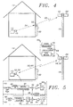
Figure 4 is a schematic representation of a base transmitter associated with a utility meter which transmits a first radio signal representative of the utility meter reading to a relay transceiver, the relay transceiver then relaying the data to a remote receive disposed upon a utility pole or the like; -
Figure 5 shows the schematic representation ofFigure 2 and includes further detail of the base transmitter and remote receiver; -
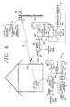
Figure 6 shows the schematic representation ofFigure 4 and includes further detail of the relay transceiver; and -
Figure 7 is a schematic representation of a single home having a cellular data modem for receiving radio signals from at least one base transmitter so as to transmit a utility meter reading thereof to a central billing office via the cellular telephone network. - The detailed description set forth below in connection with the appended drawings is intended as description of the presently preferred embodiment of the invention and is not intended to represent the only form in which the present invention may be constructed or utilized. The description sets forth the functions and the sequence of steps for constructing and operating the invention in connection with the illustrated embodiment. It is to be understood, however, that the same or equivalent functions and sequences may be accomplished by different embodiments that are also intended to be encompassed within the spirit and scope of the invention.
- The utility meter reading system of the present invention is illustrated in
Figures 1-7 which depict a presently preferred embodiment thereof. - Referring now to
Figures 1 and2 , the present invention generally comprises a plurality ofbase transmitters 10, eachbase transmitter 10 being associated with autility meter 12. - Each
base transmitter 10 is in communication with its associatedutility meter 12, preferably via direct electrical connection thereto. Thus, eachbase transmitter 10 receives a signal representative of the reading of theutility meter 12, such that it may be transmitted therefrom as a first radio signal. - Optionally, a plurality of
separate utility meters 12 may be connected to asingle transmitter base 10. Thus, in a typical residence the electric, gas, and water meters may either each have their own,individual base transmitters 10, or may alternative be connected to acommon base transmitter 10. As those skilled in the art will appreciate, various combinations of dedicated and shared base transmitters may be utilized, as desired. - Each
base transmitter 10 is configured to transmit, preferably at different times from one another, afirst radio signal 22 to aremote receiver 16 which is preferably disposed upon a utility pole, light pole, tower, or other comparativelyhigh structure 18 which facilitates the reception of thefirst radio signal 22 from thebase transmitters 10 in theneighborhood 20. - The
remote receiver 16 is in electrical communication with aremote transmitter 24 which is configured to transmit the information representative of the utility meter reading to a desired destination, such as a central billing office, preferably via acellular telephone signal 26 which is received by acellular base station 28. Those skilled in the art will appreciate that various different methods for communicating the information contained in the first radio signal from theremote receiver 16 to the central billing office may be utilized. For example, hardwired telephone lines, cellular telephone lines, satellite communication, etc. may be utilized. - Thus, according to a first configuration of the present invention, a utility meter reading or the like is transmitted from a
base transmitter 10 located in eachhome 14 to aremote receiver 16, typically located within or close to the neighborhood, preferably centrally located with respect thereto. The utility meter reading is then relayed to the central billing office via the most cost-effective means available. - In many instances it will be preferable to power the
base transmitter 10 via batteries, since many utility meters are not located near an electrical power source, such as an electrical outlet of the residence. Thus, in order to avoid the expense of wiring thebase transmitter 10 into the house's electrical wiring, replaceable batteries may be utilized. However, since such batteries must ultimately be removed and replaced, it is desirable to maximize their life by minimizing power consumption by thebase transmitters 10. The power consumption of thebase transmitters 10 is mitigated by the use of random or pseudo-random interval transmission and by the use of direct sequence spread spectrum modulation, as discussed in detail below. - Referring now to
Figures 3 and4 , it will be appreciated that in some instances excessive battery consumption would be required in order to provide the power necessary to transmit from abase station 10 to theremote receiver 16. In such instances, it may be preferable to provide a relay transceiver so as to facilitate operation of thenearby base transmitters 10 within a desirable range of battery power consumption. Eachrelay transceiver 32 is powered by an electrical utility, i.e., house wiring, such that it does not depend upon a battery for power. Thus, the use of such arelay transceiver 32 further enhances the life of the batteries utilized to power eachbase transmitter 10 which transmits to therelay transceiver 32. Since eachbase transmitter 10 need only consume enough power to transmit the comparatively short distance to therelay transceiver 32, rather than the much longer distance to theremote receiver 16. - When
such relay transceivers 32 are utilized, then eachbase transmitter 10 transmitting thereto is preferably configured to transmit utilizing position pulse modulation, which is a form of on-off keying. Thus, theradio signal 34 from thebase transmitter 10 to therelay transceiver 32 preferably comprises a position pulse modulated radio signal utilizing on-off keying and theradio signal 22 from therelay transceiver 32 to theremote receiver 16 preferably comprises a direct sequence spread spectrum modulated signal. - Referring now to
Figure 5 , eachbase transmitter 10 preferably comprises adata input port 40 which receives an electrical signal representative of the utility meter reading and provides that signal to amicroprocessor 42. Themicroprocessor 42 encodes the utility meter reading, as desired, and also facilitates transmission thereof at a random or pseudo-random time interval.Modulator 44 accepts the output ofmicroprocessor 42, i.e., a signal representative of the utility meter reading, and also accepts the output of thelocal oscillator 46 to effect modulationthereof. Power amplifier 48 boosts the output power of the radio frequency signal prior to its being transmitted viaantenna 50.Bandpass filter 49 defines the broadcast bandwidth of thefirst radio signal 22. -
Antenna 50 may likewise be utilized to receive a second radio signal, transmitted by aremote transmitter 52 which is filtered bybandpass filter 53 amplified viaamplifier 54 and converted to an IF frequency viamixer 56, filtered bybandpass filter 57, and then provided tomicroprocessor 42 viademodulator 58. In an alternate embodiment, a separate receive and transmit antenna may be utilized. The data output fromoutput 60 may then be utilized by themicroprocessor 42 to effect control of theutility meter 12 and/or a device which is monitored thereby. A control signal may be utilized to change the length of the time interval at which utility meter reading are taken or to cause theutility meter 12 to shut down the utility being provided, as discussed above. Further, the data output signal may be utilized to modify operation of the monitored device, so as to reduce consumption of the monitored utility during peak usage, for example. The signal provided from thedata output port 60 may also comprise a verification signal for effecting re-transmission of the utility meter reading when it has not been properly received by theremote receiver 16. - The
remote receiver 16 andtransmitter 52, preferably comprises anoscillator 64 which provides an output to both the direct sequence spread spectrumremote receiver 16 and the on-off keyremote transmitter 52, both of which utilizeantenna 66. The on-off keyremote transmitter 52 facilitates the transmission of the second radio signal 68 therefrom to the base receiver 70. - Referring now to
Figure 6 , theoptional relay transceiver 32 preferably comprises anantenna 80 for both receiving and sending radio signals. An alternate embodiment uses separate receive and transmit antenna. Bandpass filter 81 passes frequencies within the bandwidth, typically several megaHertz, where the signal from thebase transmitters 10 is located.Amplifier 82 amplifies the filtered radio frequency signal andmixer 84 converts the radio frequency signal to baseband. 1 MHzbandpass filter 86 provides broadband reception of the radio signal from thebase transmitter 10, whilenarrowband filter 88 facilitates reception thereof after and thedemodulator 90 provides the data output fromoutput port 92 to themicroprocessor 96. Data to be re-transmitted, such as that fromdata input port 94, is provided to themicroprocessor 96. The relay transceiver switches thelocal oscillator 85 frequency to a different frequency when in wide or narrowband reception.Microprocessor 96 encodes the data, as desired, and facilitates transmission thereof at a desired time. The data to be transmitted is output frommicroprocessor 96 throughmodulator 98, which utilizeslocal oscillator 85, topower amplifier 100.Bandpass filter 102 provides a signal of the desired frequency content toantenna 80. - Preferably, each remote transmitter and receiver service a neighborhood having a radius of approximately one mile, thus covering approximately six square miles.
- The on-off keying utilized to transmit from the base transmitter to the relay transceiver preferably comprises a 2,408.3 MHz radio signal. This is received by the relay transceiver when the relay transceiver is in the wideband mode. The relay transceiver's local oscillator is preferably a 2,419 MHz oscillator which mixes the 2,408.3 signal down to the relay transceiver' s IF at 10.7 MHz.
- The relay transceiver receives the on-off key modulated radio signal from the base transmitter and relays it to the remote receiver using direct sequence spread spectrum modulation at 2,414 MHz. Prior to performing the transmission to the remote receiver, the relay transceiver switches to its narrowband IF filter.
- The remote receiver receives the spread spectrum signal, demodulates it, and determines the center frequency of the transmission from the relay transceiver (or the base transmitter if no relay transceiver is utilized).
- After determining the center frequency of the radio transmission from the
relay transceiver 32, theremote receiver 16 adjusts for frequency drift thereof and can then transmit back to therelay transceiver 32 utilizing on-off key transmission at the correct frequency so that the transmission from theremote transmitter 24 to the relay transceiver can be properly received, i.e., its converted RF center frequency is within the relay transceiver IF bandwidth when therelay transceiver 32 is utilizing the narrowband filter thereof. - After receiving a radio transmission from the remote transmitter, the relay transceiver switches from direct or spread spectrum modulation to on-off key modulation and transmits to the base receiver at 2,413.545 MHz. The local receiver receives the 2,413.545 MHz signal and uses its 2,414 MHz local oscillator to mix the received radio signal down to 455 KHz IF for demodulation thereof.
- When a
relay transceiver 32 is utilized, then the circuitry of thebase transmitter 10 is modified so as to accommodate the use of pulse position modulation utilizing on/off key transmission, rather than direct sequence spread spectrum modulation. Thus, as shown inFigure 6 , themicroprocessor 42 provides its output directly toamplifier 48 where it controls passage of theoscillator signal 46 to thebandpass filter 49, thus effecting on/off keying. - Referring now to
Figure 7 , according to a further alternative configuration, thebase transmitter 10 associated with eachutility meter 12 of a residence, for example, transmits a radio signal representative of the meter reading to a receiver located within or near thehouse 14 which is interfaced to acellular data modem 110 viatelephone interface 112. Thecellular data modem 110 then transmits the meter reading to the central billing office via the cellular system. - It is understood that the exemplary remote utility meter reading system described herein and shown in the drawings represents only a presently preferred embodiment thereof. Indeed, various modifications and additions may be made to such embodiment. For example, those skilled in the art will appreciate various different protocols and modulation methods are suitable for the transmission of data between the base transmitter, relay transceiver, and the remote receiver. Also, various different parameters, other than utility meter readings, may be so transmitted. Thus, these and other modifications and additions may be obvious to those skilled in the art and may be implemented to adapt the present invention for use in a variety of different applications.
Claims (18)
- A method for transmitting a desired parameter from a base station including a base transmitter (10) to a remote receiver (16) at a remote location, the method comprising the steps of:a) transmitting a first radio signal (22) via pulse position modulation from the base transmitter (10) to a relay transceiver (32) disposed at location intermediate the base station and the remote location, the first radio signal (22) initiating communication between the transceiver (32) and the base station, wherein the first radio signal (22) includes a center frequency unknown to the remote receiver (16) within a frequency band known to the remote receiver (16);b) receiving the first radio signal at the relay transceiver (32);c) relaying data via direct sequence spread spectrum modulation from the relay transceiver (32) to the remote receiver (16); andd) identifying the center frequency of the first radio signal (22) at the remote receiver (16) to facilitate reception of the signal (22).
- The method as recited in Claim 1, further comprising the step of transmitting a second radio signal (68) from the remote location to the base station, the second radio signal (68) comprising instructions for regulating operation of at least one device.
- The method as recited in Claim 1, wherein the step of transmitting a first radio signal (22) comprises transmitting a first radio signal (22) having a duration of less than approximately 100 milliseconds so as to mitigate communications contention.
- The method as recited in Claim 1, further comprising the steps of:a) compressing data representative of the desired parameter;b) storing the compressed data: andc) transmitting the compressed data to a desired location via telephone at a time when telephone rates are favourable.
- The method as recited in Claim 1, wherein the step of transmitting a first radio signal (22) comprises transmitting a first radio signal (22) representative of a utility meter reading.
- The method as recited in Claim 1 wherein the base transmitter (10) is connected to a utility meter (12).
- The method as recited in Claim 1 wherein the base transmitter (10) is connected to a plurality of utility meters (12).
- The method as recited in Claim 1 wherein the step of transmitting a first radio signal (22) includes transmitting the first radio signal (22) at a random time interval to mitigate communication contention and to conserve power.
- The method as recited in Claim 2 wherein the second radio signal (68) includes instructions for regulating the operation of a utility meter (12).
- A system for transmitting a desired parameter from a base station to a remote receiver (16) at a remote location, the system comprising:a) a base transmitter disposed at the base station and configured to transmit a first radio signal (22) via pulse position modulation to a relay transceiver (32) disposed at a location intermediate the base station and the remote location, the first radio signal (22) initiating communication between the transceiver (32) and the base station, wherein the first radio signal (22) includes center frequency unknown to the remote receiver (16) within a frequency band known to the remote receiver (16)); andb) a relay transceiver (32) configured to receive the pulse position modulated first radio signal (22), and to relay the data via direct sequence spread spectrum modulation from the relay transceiver (32) to the remote location;c) the remote receiver (16) configured to facilitate reception of the first radio signal (22) by identifying the center frequency thereof.
- The system as recited in Claim 10, wherein the relay transmitter (32) is configured to transmit a second radio signal (68) from the remote location to the base station, the second radio signal (68) comprising instructions for regulating operation of at least one device.
- The system as recited in Claim 10, wherein the base transmitter (10) as configured to transmit a first radio signal (22) having a duration of less than approximately 100 milliseconds so as to mitigate communications contention.
- The system as recited in claim 10 further comprising:a) a circuit for compressing data representative of the desired parameter; andb) a memory for storing the compressed data;c) wherein compressing and storing the data facilitate subsequent transmission of the compressed data to a desired location via telephone at a time when telephone rates are favourable.
- The system as recited in Claim 10, wherein the base transmitter (10) is configured to transmit a first radio signal (22) representative of a utility meter reading.
- The system as recited in Claim 10 wherein the base transmitter (10) is connected to a utility meter (12).
- The system as recited in Claim 10 wherein the base transmitter (10) is connected to a plurality of utility meters (12).
- The system as recited in Claim 10 further comprising a timing circuit in electrical communication with the base transmitter (10), the timing circuit being operative to control transmission of the first signal (22) at a random time interval to mitigate communication contention and to conserve power.
- The system as recited in Claim 11 wherein the second radio signal (68) includes instructions for regulating the operation of a utility meter (12).
Applications Claiming Priority (3)
| Application Number | Priority Date | Filing Date | Title |
|---|---|---|---|
| US08/801,407 US5801643A (en) | 1996-06-20 | 1997-02-20 | Remote utility meter reading system |
| US801407 | 1997-02-20 | ||
| PCT/US1998/000384 WO1998037528A1 (en) | 1997-02-20 | 1998-01-12 | Remote utility meter reading system |
Publications (3)
| Publication Number | Publication Date |
|---|---|
| EP0962003A1 EP0962003A1 (en) | 1999-12-08 |
| EP0962003A4 EP0962003A4 (en) | 2007-08-01 |
| EP0962003B1 true EP0962003B1 (en) | 2009-08-26 |
Family
ID=25181010
Family Applications (1)
| Application Number | Title | Priority Date | Filing Date |
|---|---|---|---|
| EP98904537A Expired - Lifetime EP0962003B1 (en) | 1997-02-20 | 1998-01-12 | Remote utility meter reading system |
Country Status (5)
| Country | Link |
|---|---|
| US (1) | US5801643A (en) |
| EP (1) | EP0962003B1 (en) |
| JP (1) | JP2002512749A (en) |
| DE (1) | DE69841093D1 (en) |
| WO (1) | WO1998037528A1 (en) |
Families Citing this family (164)
| Publication number | Priority date | Publication date | Assignee | Title |
|---|---|---|---|---|
| US8982856B2 (en) | 1996-12-06 | 2015-03-17 | Ipco, Llc | Systems and methods for facilitating wireless network communication, satellite-based wireless network systems, and aircraft-based wireless network systems, and related methods |
| US7054271B2 (en) | 1996-12-06 | 2006-05-30 | Ipco, Llc | Wireless network system and method for providing same |
| US6396839B1 (en) | 1997-02-12 | 2002-05-28 | Abb Automation Inc. | Remote access to electronic meters using a TCP/IP protocol suite |
| US6233327B1 (en) | 1997-02-14 | 2001-05-15 | Statsignal Systems, Inc. | Multi-function general purpose transceiver |
| US7137550B1 (en) | 1997-02-14 | 2006-11-21 | Statsignal Ipc, Llc | Transmitter for accessing automated financial transaction machines |
| US7079810B2 (en) | 1997-02-14 | 2006-07-18 | Statsignal Ipc, Llc | System and method for communicating with a remote communication unit via the public switched telephone network (PSTN) |
| US6073169A (en) | 1997-04-08 | 2000-06-06 | Abb Power T&D Company Inc. | Automatic meter reading system employing common broadcast command channel |
| US6035266A (en) | 1997-04-16 | 2000-03-07 | A.L. Air Data, Inc. | Lamp monitoring and control system and method |
| US6714895B2 (en) * | 2000-06-28 | 2004-03-30 | A.L. Air Data, Inc. | Lamp monitoring and control unit and method |
| US5986574A (en) * | 1997-10-16 | 1999-11-16 | Peco Energy Company | System and method for communication between remote locations |
| US20020120569A1 (en) * | 1997-10-16 | 2002-08-29 | Day Mark E. | System and method for communication between remote locations |
| US8410931B2 (en) | 1998-06-22 | 2013-04-02 | Sipco, Llc | Mobile inventory unit monitoring systems and methods |
| US6891838B1 (en) | 1998-06-22 | 2005-05-10 | Statsignal Ipc, Llc | System and method for monitoring and controlling residential devices |
| US6914533B2 (en) | 1998-06-22 | 2005-07-05 | Statsignal Ipc Llc | System and method for accessing residential monitoring devices |
| US6437692B1 (en) | 1998-06-22 | 2002-08-20 | Statsignal Systems, Inc. | System and method for monitoring and controlling remote devices |
| US6914893B2 (en) | 1998-06-22 | 2005-07-05 | Statsignal Ipc, Llc | System and method for monitoring and controlling remote devices |
| US7103511B2 (en) | 1998-10-14 | 2006-09-05 | Statsignal Ipc, Llc | Wireless communication networks for providing remote monitoring of devices |
| US7263073B2 (en) | 1999-03-18 | 2007-08-28 | Statsignal Ipc, Llc | Systems and methods for enabling a mobile user to notify an automated monitoring system of an emergency situation |
| US7650425B2 (en) | 1999-03-18 | 2010-01-19 | Sipco, Llc | System and method for controlling communication between a host computer and communication devices associated with remote devices in an automated monitoring system |
| WO2000074402A1 (en) | 1999-05-28 | 2000-12-07 | Afx Technology Group International, Inc. | Wireless transceiver network employing node-to-node data messaging |
| AU2618101A (en) * | 1999-10-27 | 2001-06-06 | American Innovations, Ltd. | System and method for remotely reading utility meters |
| US6411219B1 (en) | 1999-12-29 | 2002-06-25 | Siemens Power Transmission And Distribution, Inc. | Adaptive radio communication for a utility meter |
| MXPA02007139A (en) * | 2000-01-20 | 2004-09-06 | Current Tech Llc | Method of isolating data in a power line communication network. |
| US8019836B2 (en) | 2002-01-02 | 2011-09-13 | Mesh Comm, Llc | Wireless communication enabled meter and network |
| US6998962B2 (en) | 2000-04-14 | 2006-02-14 | Current Technologies, Llc | Power line communication apparatus and method of using the same |
| US7248158B2 (en) * | 2000-04-14 | 2007-07-24 | Current Technologies, Llc | Automated meter reading power line communication system and method |
| US6965302B2 (en) | 2000-04-14 | 2005-11-15 | Current Technologies, Llc | Power line communication system and method of using the same |
| US7103240B2 (en) * | 2001-02-14 | 2006-09-05 | Current Technologies, Llc | Method and apparatus for providing inductive coupling and decoupling of high-frequency, high-bandwidth data signals directly on and off of a high voltage power line |
| US6933857B2 (en) * | 2000-05-05 | 2005-08-23 | Charles A. Foote | Method and system for airborne meter communication |
| AU2001279241A1 (en) | 2000-08-09 | 2002-02-18 | Statsignal Systems, Inc. | Systems and methods for providing remote monitoring of electricity consumption for an electric meter |
| US6980089B1 (en) * | 2000-08-09 | 2005-12-27 | Current Technologies, Llc | Non-intrusive coupling to shielded power cable |
| WO2002025987A2 (en) * | 2000-09-21 | 2002-03-28 | James Robert Orlosky | Automated meter reading, billing, and payment processing system |
| US6670909B2 (en) * | 2001-01-16 | 2003-12-30 | Time Domain Corporation | Ultra-wideband smart sensor interface network and method |
| EP1371219A4 (en) * | 2001-02-14 | 2006-06-21 | Current Tech Llc | Data communication over a power line |
| SE522224C2 (en) * | 2001-05-08 | 2004-01-27 | Abb As | Electrical energy distribution system and remote measurement of electricity as well as distribution unit and a switchgear |
| US7346463B2 (en) | 2001-08-09 | 2008-03-18 | Hunt Technologies, Llc | System for controlling electrically-powered devices in an electrical network |
| US7009530B2 (en) * | 2001-09-13 | 2006-03-07 | M&Fc Holding, Llc | Modular wireless fixed network for wide-area metering data collection and meter module apparatus |
| US7385524B1 (en) | 2001-09-21 | 2008-06-10 | James Robert Orlosky | Automated meter reading, billing and payment processing system |
| US20030063723A1 (en) * | 2001-09-28 | 2003-04-03 | Derek Booth | Interactive system for managing and remotely connecting customer utility loads |
| US8489063B2 (en) | 2001-10-24 | 2013-07-16 | Sipco, Llc | Systems and methods for providing emergency messages to a mobile device |
| US7480501B2 (en) | 2001-10-24 | 2009-01-20 | Statsignal Ipc, Llc | System and method for transmitting an emergency message over an integrated wireless network |
| US7424527B2 (en) | 2001-10-30 | 2008-09-09 | Sipco, Llc | System and method for transmitting pollution information over an integrated wireless network |
| US20030179149A1 (en) * | 2001-11-26 | 2003-09-25 | Schlumberger Electricity, Inc. | Embedded antenna apparatus for utility metering applications |
| US7053756B2 (en) | 2001-12-21 | 2006-05-30 | Current Technologies, Llc | Facilitating communication of data signals on electric power systems |
| US7102478B2 (en) | 2002-06-21 | 2006-09-05 | Current Technologies, Llc | Power line coupling device and method of using the same |
| US6982611B2 (en) * | 2002-06-24 | 2006-01-03 | Current Technologies, Llc | Power line coupling device and method of using the same |
| US7119713B2 (en) | 2002-06-27 | 2006-10-10 | Elster Electricity, Llc | Dynamic self-configuring metering network |
| US20040113810A1 (en) | 2002-06-28 | 2004-06-17 | Mason Robert T. | Data collector for an automated meter reading system |
| US7002472B2 (en) * | 2002-09-04 | 2006-02-21 | Northrop Grumman Corporation | Smart and secure container |
| US7132819B1 (en) | 2002-11-12 | 2006-11-07 | Current Technologies, Llc | Floating power supply and method of using the same |
| US7444401B1 (en) | 2002-11-18 | 2008-10-28 | Arkion Systems Llc | Method and apparatus for inexpensively monitoring and controlling remotely distributed appliances |
| US6996215B2 (en) * | 2002-11-27 | 2006-02-07 | Macconnell John Walter | Telemetry system and method |
| US6980091B2 (en) | 2002-12-10 | 2005-12-27 | Current Technologies, Llc | Power line communication system and method of operating the same |
| US6980090B2 (en) | 2002-12-10 | 2005-12-27 | Current Technologies, Llc | Device and method for coupling with electrical distribution network infrastructure to provide communications |
| US7436321B2 (en) * | 2002-12-10 | 2008-10-14 | Current Technologies, Llc | Power line communication system with automated meter reading |
| US6965303B2 (en) | 2002-12-10 | 2005-11-15 | Current Technologies, Llc | Power line communication system and method |
| US7075414B2 (en) | 2003-05-13 | 2006-07-11 | Current Technologies, Llc | Device and method for communicating data signals through multiple power line conductors |
| US7154938B2 (en) * | 2002-12-31 | 2006-12-26 | Itron, Inc. | RF communications system utilizing digital modulation to transmit and receive data |
| US7046124B2 (en) | 2003-01-21 | 2006-05-16 | Current Technologies, Llc | Power line coupling device and method of using the same |
| US6954144B1 (en) | 2003-05-30 | 2005-10-11 | Amco Automated Systems, Inc. | Water pit transmitter assembly |
| US20040259523A1 (en) * | 2003-06-16 | 2004-12-23 | Stenger Thomas L. | Wireless meter reading (WMR) |
| US7099770B2 (en) * | 2003-09-08 | 2006-08-29 | Axonn L.L.C. | Location monitoring and transmitting device, method, and computer program product using a simplex satellite transmitter |
| US20050113060A1 (en) * | 2003-10-17 | 2005-05-26 | Lowery Kenneth E. | Wireless network system |
| US7756086B2 (en) | 2004-03-03 | 2010-07-13 | Sipco, Llc | Method for communicating in dual-modes |
| US8031650B2 (en) | 2004-03-03 | 2011-10-04 | Sipco, Llc | System and method for monitoring remote devices with a dual-mode wireless communication protocol |
| US7187906B2 (en) | 2004-04-26 | 2007-03-06 | Elster Electricity, Llc | Method and system for configurable qualification and registration in a fixed network automated meter reading system |
| US7262709B2 (en) | 2004-04-26 | 2007-08-28 | Elster Electricity, Llc | System and method for efficient configuration in a fixed network automated meter reading system |
| US7239250B2 (en) | 2004-04-26 | 2007-07-03 | Elster Electricity, Llc | System and method for improved transmission of meter data |
| US7142106B2 (en) | 2004-06-15 | 2006-11-28 | Elster Electricity, Llc | System and method of visualizing network layout and performance characteristics in a wireless network |
| US7742430B2 (en) | 2004-09-24 | 2010-06-22 | Elster Electricity, Llc | System for automated management of spontaneous node migration in a distributed fixed wireless network |
| US7702594B2 (en) | 2004-09-24 | 2010-04-20 | Elster Electricity, Llc | System and method for automated configuration of meters |
| US7170425B2 (en) | 2004-09-24 | 2007-01-30 | Elster Electricity, Llc | System and method for creating multiple operating territories within a meter reading system |
| US7176807B2 (en) | 2004-09-24 | 2007-02-13 | Elster Electricity, Llc | System for automatically enforcing a demand reset in a fixed network of electricity meters |
| US20060141940A1 (en) * | 2004-10-12 | 2006-06-29 | Bloom David L | Intelligent bridge between PSTN and asynchronous communication channel |
| US7304586B2 (en) * | 2004-10-20 | 2007-12-04 | Electro Industries / Gauge Tech | On-line web accessed energy meter |
| US9080894B2 (en) * | 2004-10-20 | 2015-07-14 | Electro Industries/Gauge Tech | Intelligent electronic device for receiving and sending data at high speeds over a network |
| US7747733B2 (en) | 2004-10-25 | 2010-06-29 | Electro Industries/Gauge Tech | Power meter having multiple ethernet ports |
| US7327998B2 (en) | 2004-12-22 | 2008-02-05 | Elster Electricity, Llc | System and method of providing a geographic view of nodes in a wireless network |
| US9439126B2 (en) | 2005-01-25 | 2016-09-06 | Sipco, Llc | Wireless network protocol system and methods |
| US8190381B2 (en) | 2005-01-27 | 2012-05-29 | Electro Industries/Gauge Tech | Intelligent electronic device with enhanced power quality monitoring and communications capabilities |
| US8620608B2 (en) | 2005-01-27 | 2013-12-31 | Electro Industries/Gauge Tech | Intelligent electronic device and method thereof |
| US8930153B2 (en) | 2005-01-27 | 2015-01-06 | Electro Industries/Gauge Tech | Metering device with control functionality and method thereof |
| US8160824B2 (en) | 2005-01-27 | 2012-04-17 | Electro Industries/Gauge Tech | Intelligent electronic device with enhanced power quality monitoring and communication capabilities |
| US7308370B2 (en) | 2005-03-22 | 2007-12-11 | Elster Electricity Llc | Using a fixed network wireless data collection system to improve utility responsiveness to power outages |
| ES2261078B1 (en) * | 2005-04-25 | 2007-11-16 | Servicios Informaticos Kifer, S.L. | UNIVERSAL AND RECONFIGURABLE METHOD AND SYSTEM FOR REMOTE READING OF METERS OR EQUIPMENT PROVIDED WITH VISUAL INDICATORS. |
| US7627453B2 (en) | 2005-04-26 | 2009-12-01 | Current Communications Services, Llc | Power distribution network performance data presentation system and method |
| US7495578B2 (en) | 2005-09-02 | 2009-02-24 | Elster Electricity, Llc | Multipurpose interface for an automated meter reading device |
| US7308369B2 (en) | 2005-09-28 | 2007-12-11 | Elster Electricity Llc | Ensuring automatic season change demand resets in a mesh type network of telemetry devices |
| US8515348B2 (en) | 2005-10-28 | 2013-08-20 | Electro Industries/Gauge Tech | Bluetooth-enable intelligent electronic device |
| DE102005056933A1 (en) * | 2005-11-29 | 2007-05-31 | Prof. Dr. Horst Ziegler und Partner GbR (vertretungsberechtigter Gesellschafter: Prof. Dr. Horst Ziegler 33100 Paderborn) | Radio transmission system |
| US7769149B2 (en) * | 2006-01-09 | 2010-08-03 | Current Communications Services, Llc | Automated utility data services system and method |
| US20080012724A1 (en) * | 2006-01-30 | 2008-01-17 | Corcoran Kevin F | Power line communications module and method |
| US7545285B2 (en) | 2006-02-16 | 2009-06-09 | Elster Electricity, Llc | Load control unit in communication with a fixed network meter reading system |
| US7427927B2 (en) | 2006-02-16 | 2008-09-23 | Elster Electricity, Llc | In-home display communicates with a fixed network meter reading system |
| US8457576B2 (en) * | 2006-03-23 | 2013-06-04 | Marvell International Ltd. | Cellular phone with integrated FM radio and remote low noise amplifier |
| WO2007131169A2 (en) | 2006-05-04 | 2007-11-15 | Capstone Mobile Technologies, Llc | System and method for remotely monitoring and controlling a water meter |
| US8690117B2 (en) | 2006-05-04 | 2014-04-08 | Capstone Metering Llc | Water meter |
| US8312103B2 (en) * | 2006-08-31 | 2012-11-13 | Itron, Inc. | Periodic balanced communication node and server assignment |
| US20080071930A1 (en) * | 2006-09-01 | 2008-03-20 | Holbrook Kenneth J | Native network transport |
| US7843391B2 (en) * | 2006-09-15 | 2010-11-30 | Itron, Inc. | RF local area network antenna design |
| US8055461B2 (en) | 2006-09-15 | 2011-11-08 | Itron, Inc. | Distributing metering responses for load balancing an AMR network |
| US8073384B2 (en) | 2006-12-14 | 2011-12-06 | Elster Electricity, Llc | Optimization of redundancy and throughput in an automated meter data collection system using a wireless network |
| US7920976B2 (en) | 2007-03-27 | 2011-04-05 | Electro Industries / Gauge Tech. | Averaging in an intelligent electronic device |
| US7973673B2 (en) * | 2007-04-02 | 2011-07-05 | Itron, Inc. | Automated meter reader direct mount endpoint module |
| US20130275066A1 (en) | 2007-04-03 | 2013-10-17 | Electro Industries/Gaugetech | Digital power metering system |
| US11307227B2 (en) | 2007-04-03 | 2022-04-19 | Electro Industries/Gauge Tech | High speed digital transient waveform detection system and method for use in an intelligent electronic device |
| US10845399B2 (en) | 2007-04-03 | 2020-11-24 | Electro Industries/Gaugetech | System and method for performing data transfers in an intelligent electronic device |
| US9989618B2 (en) | 2007-04-03 | 2018-06-05 | Electro Industries/Gaugetech | Intelligent electronic device with constant calibration capabilities for high accuracy measurements |
| US8320302B2 (en) | 2007-04-20 | 2012-11-27 | Elster Electricity, Llc | Over the air microcontroller flash memory updates |
| US20090125351A1 (en) * | 2007-11-08 | 2009-05-14 | Davis Jr Robert G | System and Method for Establishing Communications with an Electronic Meter |
| NZ586190A (en) | 2007-12-26 | 2013-05-31 | Elster Electricity Llc | A utility meter network wherein meters can transmit electrical and other readings to a collector by using other meters as repeaters |
| US20090210178A1 (en) * | 2008-02-15 | 2009-08-20 | Paul Bieganski | Systems and methods for producing power consumption data |
| US20090207753A1 (en) * | 2008-02-15 | 2009-08-20 | Paul Bieganski | Systems and methods for power consumption data networks |
| US12061218B2 (en) | 2008-03-13 | 2024-08-13 | Ei Electronics Llc | System and method for multi-rate concurrent waveform capture and storage for power quality metering |
| US9482555B2 (en) | 2008-04-03 | 2016-11-01 | Electro Industries/Gauge Tech. | System and method for improved data transfer from an IED |
| US8525692B2 (en) | 2008-06-13 | 2013-09-03 | Elster Solutions, Llc | Techniques for limiting demand from an electricity meter with an installed relay |
| WO2010035137A2 (en) * | 2008-09-26 | 2010-04-01 | Telenor Asa | Secure managed data collection and transmission |
| US9202362B2 (en) * | 2008-10-27 | 2015-12-01 | Mueller International, Llc | Infrastructure monitoring system and method |
| US8199027B1 (en) * | 2008-11-19 | 2012-06-12 | Jack Rubin | Systems and methods for utility meter reading |
| US8203463B2 (en) | 2009-02-13 | 2012-06-19 | Elster Electricity Llc | Wakeup and interrogation of meter-reading devices using licensed narrowband and unlicensed wideband radio communication |
| US20100262395A1 (en) * | 2009-04-08 | 2010-10-14 | Manu Sharma | System and Method for Determining a Phase Conductor Supplying Power to a Device |
| US20100262393A1 (en) * | 2009-04-08 | 2010-10-14 | Manu Sharma | System and Method for Determining a Phase Conductor Supplying Power to a Device |
| JP2012527706A (en) | 2009-05-22 | 2012-11-08 | ミューラー インターナショナル インコーポレイテッド | Infrastructure monitoring apparatus, system, and method |
| BR112012009449A2 (en) * | 2009-09-25 | 2016-06-14 | Itron Inc | telemetry system |
| US8484138B2 (en) * | 2009-09-29 | 2013-07-09 | Itron, Inc. | Combined cathodic protection and meter reading monitoring system |
| US9510066B2 (en) * | 2009-09-29 | 2016-11-29 | Itron, Inc. | Collection of telemetry data through a meter reading system |
| US8330669B2 (en) | 2010-04-22 | 2012-12-11 | Itron, Inc. | Remote antenna coupling in an AMR device |
| WO2011159403A1 (en) | 2010-06-16 | 2011-12-22 | Mueller International, Llc | Infrastructure monitoring devices, systems, and methods |
| BRPI1100227A8 (en) * | 2011-02-18 | 2015-10-27 | João Machado Magalhães De Almeida | modular measurement and control collection management system for energy, water and gas |
| JP5715868B2 (en) * | 2011-03-31 | 2015-05-13 | 関西電力株式会社 | Meter terminal, meter reading data collecting system and meter reading data collecting method |
| US8833390B2 (en) | 2011-05-31 | 2014-09-16 | Mueller International, Llc | Valve meter assembly and method |
| US10275840B2 (en) | 2011-10-04 | 2019-04-30 | Electro Industries/Gauge Tech | Systems and methods for collecting, analyzing, billing, and reporting data from intelligent electronic devices |
| US10303860B2 (en) | 2011-10-04 | 2019-05-28 | Electro Industries/Gauge Tech | Security through layers in an intelligent electronic device |
| US10771532B2 (en) | 2011-10-04 | 2020-09-08 | Electro Industries/Gauge Tech | Intelligent electronic devices, systems and methods for communicating messages over a network |
| US12457127B2 (en) | 2011-10-04 | 2025-10-28 | Ei Electronics Llc | Internet of things (IoT) intelligent electronic devices, systems and methods |
| US12260078B2 (en) | 2011-10-04 | 2025-03-25 | Ei Electronics Llc | Dynamic webpage interface for an intelligent electronic device |
| US10862784B2 (en) | 2011-10-04 | 2020-12-08 | Electro Industries/Gauge Tech | Systems and methods for processing meter information in a network of intelligent electronic devices |
| US20150356104A9 (en) | 2011-10-04 | 2015-12-10 | Electro Industries/Gauge Tech | Systems and methods for collecting, analyzing, billing, and reporting data from intelligent electronic devices |
| US10200476B2 (en) | 2011-10-18 | 2019-02-05 | Itron, Inc. | Traffic management and remote configuration in a gateway-based network |
| US8855569B2 (en) | 2011-10-27 | 2014-10-07 | Mueller International, Llc | Systems and methods for dynamic squelching in radio frequency devices |
| US8660134B2 (en) | 2011-10-27 | 2014-02-25 | Mueller International, Llc | Systems and methods for time-based hailing of radio frequency devices |
| US9425854B2 (en) * | 2012-06-18 | 2016-08-23 | Alstom Transport Technologies | Spread spectrum signals in vehicle network systems |
| US9005423B2 (en) | 2012-12-04 | 2015-04-14 | Itron, Inc. | Pipeline communications |
| US11816465B2 (en) | 2013-03-15 | 2023-11-14 | Ei Electronics Llc | Devices, systems and methods for tracking and upgrading firmware in intelligent electronic devices |
| EP2972139A4 (en) | 2013-03-15 | 2016-10-12 | Mueller Int Llc | SYSTEMS FOR MEASURING WATER PROPERTIES IN A WATER DISTRIBUTION SYSTEM |
| WO2015089021A2 (en) | 2013-12-09 | 2015-06-18 | Dataflyte, Inc. | Airborne data collection |
| US9494249B2 (en) | 2014-05-09 | 2016-11-15 | Mueller International, Llc | Mechanical stop for actuator and orifice |
| US11734396B2 (en) | 2014-06-17 | 2023-08-22 | El Electronics Llc | Security through layers in an intelligent electronic device |
| US9565620B2 (en) | 2014-09-02 | 2017-02-07 | Mueller International, Llc | Dynamic routing in a mesh network |
| US11009922B2 (en) | 2015-02-27 | 2021-05-18 | Electro Industries/Gaugetech | Wireless intelligent electronic device |
| US9897461B2 (en) | 2015-02-27 | 2018-02-20 | Electro Industries/Gauge Tech | Intelligent electronic device with expandable functionality |
| US10048088B2 (en) | 2015-02-27 | 2018-08-14 | Electro Industries/Gauge Tech | Wireless intelligent electronic device |
| US11041839B2 (en) | 2015-06-05 | 2021-06-22 | Mueller International, Llc | Distribution system monitoring |
| US10958435B2 (en) | 2015-12-21 | 2021-03-23 | Electro Industries/ Gauge Tech | Providing security in an intelligent electronic device |
| US10430263B2 (en) | 2016-02-01 | 2019-10-01 | Electro Industries/Gauge Tech | Devices, systems and methods for validating and upgrading firmware in intelligent electronic devices |
| DE102016009197B3 (en) * | 2016-04-26 | 2017-07-27 | Diehl Metering Systems Gmbh | Method and device for bidirectional communication between measuring devices and data collectors |
| US10340589B2 (en) | 2016-06-10 | 2019-07-02 | Aclara Technologies Llc | Capacitively coupled external antenna system and method for electric meters |
| ITUA20164986A1 (en) * | 2016-06-17 | 2017-12-17 | Luigi Pizzini | ELECTRONIC DEVICE FOR REMOTE REMOTE READING OF TWO WATER METERS FOR AQUEDUCTS OR IRRIGUE SYSTEMS, IN UNITARY VIA RADIO MODE WITH FREE FREQUENCY |
| US11686594B2 (en) | 2018-02-17 | 2023-06-27 | Ei Electronics Llc | Devices, systems and methods for a cloud-based meter management system |
| US11734704B2 (en) | 2018-02-17 | 2023-08-22 | Ei Electronics Llc | Devices, systems and methods for the collection of meter data in a common, globally accessible, group of servers, to provide simpler configuration, collection, viewing, and analysis of the meter data |
| US11754997B2 (en) | 2018-02-17 | 2023-09-12 | Ei Electronics Llc | Devices, systems and methods for predicting future consumption values of load(s) in power distribution systems |
| US12288058B2 (en) | 2018-09-20 | 2025-04-29 | Ei Electronics Llc | Devices, systems and methods for tracking and upgrading firmware in intelligent electronic devices |
| US11863589B2 (en) | 2019-06-07 | 2024-01-02 | Ei Electronics Llc | Enterprise security in meters |
| US11725366B2 (en) | 2020-07-16 | 2023-08-15 | Mueller International, Llc | Remote-operated flushing system |
Family Cites Families (22)
| Publication number | Priority date | Publication date | Assignee | Title |
|---|---|---|---|---|
| US4322842A (en) * | 1979-10-23 | 1982-03-30 | Altran Electronics | Broadcast system for distribution automation and remote metering |
| US4636950A (en) * | 1982-09-30 | 1987-01-13 | Caswell Robert L | Inventory management system using transponders associated with specific products |
| US4614945A (en) * | 1985-02-20 | 1986-09-30 | Diversified Energies, Inc. | Automatic/remote RF instrument reading method and apparatus |
| US4639728A (en) * | 1985-09-16 | 1987-01-27 | Sangamo Weston, Inc. | Method of and system for accumulating verifiable energy demand data from remote electricity meters |
| US5005125A (en) * | 1986-02-28 | 1991-04-02 | Sensormatic Electronics Corporation | Surveillance, pricing and inventory system |
| US4713837A (en) * | 1985-12-24 | 1987-12-15 | Alastair Gordon | Communication network |
| US4862493A (en) * | 1987-12-28 | 1989-08-29 | General Electric Company | Electronic remote data recorder for electric energy metering |
| US4940976A (en) * | 1988-02-05 | 1990-07-10 | Utilicom Inc. | Automated remote water meter readout system |
| GB2238147B (en) * | 1989-11-16 | 1993-04-21 | Gen Electric Co Plc | Radio telemetry systems |
| US5056107A (en) * | 1990-02-15 | 1991-10-08 | Iris Systems Inc. | Radio communication network for remote data generating stations |
| US5553094A (en) * | 1990-02-15 | 1996-09-03 | Iris Systems, Inc. | Radio communication network for remote data generating stations |
| GB9009739D0 (en) * | 1990-05-01 | 1990-06-20 | Disys Inc | Transponder system |
| US5216623A (en) * | 1990-06-06 | 1993-06-01 | M. T. Mcbrian, Inc. | System and method for monitoring and analyzing energy characteristics |
| IT1255183B (en) * | 1992-06-26 | 1995-10-20 | Luciano Manenti | ADDRESSABLE REMOTE TRANSDUCER WITH AUTOMATIC CALIBRATION AND DIGITAL COMPENSATION |
| EP0604777A1 (en) * | 1992-12-28 | 1994-07-06 | Motorola, Inc. | Data transmission device system and method |
| US5485148A (en) * | 1993-03-31 | 1996-01-16 | Tseng; Ling-Yuan | Pipeline fluid travel monitoring system |
| US5299227A (en) * | 1993-04-13 | 1994-03-29 | American Electronics, Inc. | Individual beacon identification system |
| US5438329A (en) * | 1993-06-04 | 1995-08-01 | M & Fc Holding Company, Inc. | Duplex bi-directional multi-mode remote instrument reading and telemetry system |
| US5451938A (en) * | 1993-10-22 | 1995-09-19 | Schlumberger Industries, Inc. | RF meter reading system |
| US5654978A (en) * | 1993-11-01 | 1997-08-05 | Omnipoint Corporation | Pulse position modulation with spread spectrum |
| US5481259A (en) * | 1994-05-02 | 1996-01-02 | Motorola, Inc. | Method for reading a plurality of remote meters |
| US5541589A (en) * | 1994-12-15 | 1996-07-30 | Delaney; Patrick J. | Power meter data acquisition and control system |
-
1997
- 1997-02-20 US US08/801,407 patent/US5801643A/en not_active Expired - Lifetime
-
1998
- 1998-01-12 WO PCT/US1998/000384 patent/WO1998037528A1/en not_active Ceased
- 1998-01-12 DE DE69841093T patent/DE69841093D1/en not_active Expired - Lifetime
- 1998-01-12 EP EP98904537A patent/EP0962003B1/en not_active Expired - Lifetime
- 1998-01-12 JP JP53662198A patent/JP2002512749A/en active Pending
Also Published As
| Publication number | Publication date |
|---|---|
| WO1998037528A1 (en) | 1998-08-27 |
| EP0962003A1 (en) | 1999-12-08 |
| US5801643A (en) | 1998-09-01 |
| JP2002512749A (en) | 2002-04-23 |
| EP0962003A4 (en) | 2007-08-01 |
| DE69841093D1 (en) | 2009-10-08 |
Similar Documents
| Publication | Publication Date | Title |
|---|---|---|
| US5801643A (en) | Remote utility meter reading system | |
| JP3485187B2 (en) | Electronic electric meter for networked meter reading | |
| EP1488660B1 (en) | A method and apparatus for wireless remote telemetry using ad-hoc networks | |
| US7417557B2 (en) | Applications for a low cost receiver in an automatic meter reading system | |
| CA2723665C (en) | Mobile network back-up for fixed meter reading networks | |
| US20110038288A1 (en) | Mobile automatic meter reading system and method | |
| CA1257654A (en) | Wireless local area network for use in neighborhoods | |
| EP0701727B1 (en) | Duplex bi-directional multi-mode remote instrument reading and telemetry system | |
| US7479895B2 (en) | Data communication protocol in an automatic meter reading system | |
| CA2724013C (en) | Apparatus and method for establishing communication from remote sites in a fixed meter reading network | |
| US7064679B2 (en) | Electronic electric meter for networked meter reading | |
| US8031082B2 (en) | RF meter reading system | |
| US6411219B1 (en) | Adaptive radio communication for a utility meter | |
| US20040125889A1 (en) | RF communications system utilizing digital modulation to transmit and receive data | |
| EP1512944B1 (en) | System and method for reducing signal interference between data transmission signals | |
| US20080158007A1 (en) | Data Communication Protocol in an Automatic Meter Reading System | |
| US7372372B2 (en) | Sequence inversion keyed countdown timer utilized within a utility meter system | |
| US20060038700A1 (en) | Sleeve repeater for forwarding meter data | |
| MXPA99002132A (en) | Electronic electric meter for networked meter reading | |
| AU2004205349A1 (en) | Sequence inversion keyed countdown timer utilized within a utility meter system | |
| MXPA99002134A (en) | Automatic meter reading data communication system | |
| HK1078409A (en) | A method and apparatus for wireless remote telemetry using ad-hoc networks | |
| AU2011211465A1 (en) | Data communication protocol in an automatic meter reading system |
Legal Events
| Date | Code | Title | Description |
|---|---|---|---|
| PUAI | Public reference made under article 153(3) epc to a published international application that has entered the european phase |
Free format text: ORIGINAL CODE: 0009012 |
|
| 17P | Request for examination filed |
Effective date: 19990908 |
|
| AK | Designated contracting states |
Kind code of ref document: A1 Designated state(s): DE GB |
|
| A4 | Supplementary search report drawn up and despatched |
Effective date: 20070628 |
|
| RIC1 | Information provided on ipc code assigned before grant |
Ipc: G08C 15/04 20060101ALI20070622BHEP Ipc: G08B 23/00 20060101ALI20070622BHEP Ipc: G08C 19/24 20060101ALI20070622BHEP Ipc: G08C 17/02 20060101AFI20070622BHEP |
|
| 17Q | First examination report despatched |
Effective date: 20071129 |
|
| GRAP | Despatch of communication of intention to grant a patent |
Free format text: ORIGINAL CODE: EPIDOSNIGR1 |
|
| RAP1 | Party data changed (applicant data changed or rights of an application transferred) |
Owner name: NORTHROP GRUMMAN CORPORATION |
|
| GRAS | Grant fee paid |
Free format text: ORIGINAL CODE: EPIDOSNIGR3 |
|
| GRAA | (expected) grant |
Free format text: ORIGINAL CODE: 0009210 |
|
| AK | Designated contracting states |
Kind code of ref document: B1 Designated state(s): DE GB |
|
| REG | Reference to a national code |
Ref country code: GB Ref legal event code: FG4D |
|
| REF | Corresponds to: |
Ref document number: 69841093 Country of ref document: DE Date of ref document: 20091008 Kind code of ref document: P |
|
| PLBE | No opposition filed within time limit |
Free format text: ORIGINAL CODE: 0009261 |
|
| STAA | Information on the status of an ep patent application or granted ep patent |
Free format text: STATUS: NO OPPOSITION FILED WITHIN TIME LIMIT |
|
| 26N | No opposition filed |
Effective date: 20100527 |
|
| REG | Reference to a national code |
Ref country code: GB Ref legal event code: 732E Free format text: REGISTERED BETWEEN 20110428 AND 20110504 |
|
| REG | Reference to a national code |
Ref country code: DE Ref legal event code: R082 Ref document number: 69841093 Country of ref document: DE Representative=s name: PATENTANWAELTE WALLACH, KOCH & PARTNER, DE |
|
| REG | Reference to a national code |
Ref country code: DE Ref legal event code: R082 Ref document number: 69841093 Country of ref document: DE Representative=s name: PATENTANWAELTE WALLACH, KOCH, DR. HAIBACH, FEL, DE Effective date: 20130205 Ref country code: DE Ref legal event code: R082 Ref document number: 69841093 Country of ref document: DE Representative=s name: PATENTANWAELTE WALLACH, KOCH & PARTNER, DE Effective date: 20130205 Ref country code: DE Ref legal event code: R081 Ref document number: 69841093 Country of ref document: DE Owner name: NORTHROP GRUMMAN SYSTEMS CORPORATION (N.D.GES., US Free format text: FORMER OWNER: NORTHROP GRUMMAN CORP., LOS ANGELES, CALIF., US Effective date: 20130205 Ref country code: DE Ref legal event code: R081 Ref document number: 69841093 Country of ref document: DE Owner name: NORTHROP GRUMMAN SYSTEMS CORPORATION (N.D.GES., US Free format text: FORMER OWNER: NORTHROP GRUMMAN CORP., LOS ANGELES, US Effective date: 20130205 |
|
| PGFP | Annual fee paid to national office [announced via postgrant information from national office to epo] |
Ref country code: DE Payment date: 20150121 Year of fee payment: 18 |
|
| PGFP | Annual fee paid to national office [announced via postgrant information from national office to epo] |
Ref country code: GB Payment date: 20150121 Year of fee payment: 18 |
|
| REG | Reference to a national code |
Ref country code: DE Ref legal event code: R119 Ref document number: 69841093 Country of ref document: DE |
|
| GBPC | Gb: european patent ceased through non-payment of renewal fee |
Effective date: 20160112 |
|
| PG25 | Lapsed in a contracting state [announced via postgrant information from national office to epo] |
Ref country code: DE Free format text: LAPSE BECAUSE OF NON-PAYMENT OF DUE FEES Effective date: 20160802 Ref country code: GB Free format text: LAPSE BECAUSE OF NON-PAYMENT OF DUE FEES Effective date: 20160112 |