EP0961719B1 - Inflator capable of modulating airbag inflation rate in a vehicle occupant restraint apparatus - Google Patents
Inflator capable of modulating airbag inflation rate in a vehicle occupant restraint apparatus Download PDFInfo
- Publication number
- EP0961719B1 EP0961719B1 EP98907349A EP98907349A EP0961719B1 EP 0961719 B1 EP0961719 B1 EP 0961719B1 EP 98907349 A EP98907349 A EP 98907349A EP 98907349 A EP98907349 A EP 98907349A EP 0961719 B1 EP0961719 B1 EP 0961719B1
- Authority
- EP
- European Patent Office
- Prior art keywords
- piston
- rheological fluid
- airbag
- chamber
- airbag inflator
- Prior art date
- Legal status (The legal status is an assumption and is not a legal conclusion. Google has not performed a legal analysis and makes no representation as to the accuracy of the status listed.)
- Expired - Lifetime
Links
Images

Classifications
-
- B—PERFORMING OPERATIONS; TRANSPORTING
- B60—VEHICLES IN GENERAL
- B60R—VEHICLES, VEHICLE FITTINGS, OR VEHICLE PARTS, NOT OTHERWISE PROVIDED FOR
- B60R21/00—Arrangements or fittings on vehicles for protecting or preventing injuries to occupants or pedestrians in case of accidents or other traffic risks
- B60R21/02—Occupant safety arrangements or fittings, e.g. crash pads
- B60R21/16—Inflatable occupant restraints or confinements designed to inflate upon impact or impending impact, e.g. air bags
- B60R21/26—Inflatable occupant restraints or confinements designed to inflate upon impact or impending impact, e.g. air bags characterised by the inflation fluid source or means to control inflation fluid flow
- B60R21/268—Inflatable occupant restraints or confinements designed to inflate upon impact or impending impact, e.g. air bags characterised by the inflation fluid source or means to control inflation fluid flow using instantaneous release of stored pressurised gas
-
- B—PERFORMING OPERATIONS; TRANSPORTING
- B60—VEHICLES IN GENERAL
- B60R—VEHICLES, VEHICLE FITTINGS, OR VEHICLE PARTS, NOT OTHERWISE PROVIDED FOR
- B60R21/00—Arrangements or fittings on vehicles for protecting or preventing injuries to occupants or pedestrians in case of accidents or other traffic risks
- B60R21/02—Occupant safety arrangements or fittings, e.g. crash pads
- B60R21/16—Inflatable occupant restraints or confinements designed to inflate upon impact or impending impact, e.g. air bags
- B60R21/26—Inflatable occupant restraints or confinements designed to inflate upon impact or impending impact, e.g. air bags characterised by the inflation fluid source or means to control inflation fluid flow
- B60R21/264—Inflatable occupant restraints or confinements designed to inflate upon impact or impending impact, e.g. air bags characterised by the inflation fluid source or means to control inflation fluid flow using instantaneous generation of gas, e.g. pyrotechnic
-
- B—PERFORMING OPERATIONS; TRANSPORTING
- B60—VEHICLES IN GENERAL
- B60R—VEHICLES, VEHICLE FITTINGS, OR VEHICLE PARTS, NOT OTHERWISE PROVIDED FOR
- B60R21/00—Arrangements or fittings on vehicles for protecting or preventing injuries to occupants or pedestrians in case of accidents or other traffic risks
- B60R21/02—Occupant safety arrangements or fittings, e.g. crash pads
- B60R21/16—Inflatable occupant restraints or confinements designed to inflate upon impact or impending impact, e.g. air bags
- B60R21/26—Inflatable occupant restraints or confinements designed to inflate upon impact or impending impact, e.g. air bags characterised by the inflation fluid source or means to control inflation fluid flow
-
- B—PERFORMING OPERATIONS; TRANSPORTING
- B60—VEHICLES IN GENERAL
- B60R—VEHICLES, VEHICLE FITTINGS, OR VEHICLE PARTS, NOT OTHERWISE PROVIDED FOR
- B60R21/00—Arrangements or fittings on vehicles for protecting or preventing injuries to occupants or pedestrians in case of accidents or other traffic risks
- B60R21/02—Occupant safety arrangements or fittings, e.g. crash pads
- B60R21/16—Inflatable occupant restraints or confinements designed to inflate upon impact or impending impact, e.g. air bags
- B60R21/26—Inflatable occupant restraints or confinements designed to inflate upon impact or impending impact, e.g. air bags characterised by the inflation fluid source or means to control inflation fluid flow
- B60R21/268—Inflatable occupant restraints or confinements designed to inflate upon impact or impending impact, e.g. air bags characterised by the inflation fluid source or means to control inflation fluid flow using instantaneous release of stored pressurised gas
- B60R21/272—Inflatable occupant restraints or confinements designed to inflate upon impact or impending impact, e.g. air bags characterised by the inflation fluid source or means to control inflation fluid flow using instantaneous release of stored pressurised gas with means for increasing the pressure of the gas just before or during liberation, e.g. hybrid inflators
-
- B—PERFORMING OPERATIONS; TRANSPORTING
- B60—VEHICLES IN GENERAL
- B60R—VEHICLES, VEHICLE FITTINGS, OR VEHICLE PARTS, NOT OTHERWISE PROVIDED FOR
- B60R21/00—Arrangements or fittings on vehicles for protecting or preventing injuries to occupants or pedestrians in case of accidents or other traffic risks
- B60R21/02—Occupant safety arrangements or fittings, e.g. crash pads
- B60R21/16—Inflatable occupant restraints or confinements designed to inflate upon impact or impending impact, e.g. air bags
- B60R21/26—Inflatable occupant restraints or confinements designed to inflate upon impact or impending impact, e.g. air bags characterised by the inflation fluid source or means to control inflation fluid flow
- B60R21/263—Inflatable occupant restraints or confinements designed to inflate upon impact or impending impact, e.g. air bags characterised by the inflation fluid source or means to control inflation fluid flow using a variable source, e.g. plural stage or controlled output
- B60R2021/2633—Inflatable occupant restraints or confinements designed to inflate upon impact or impending impact, e.g. air bags characterised by the inflation fluid source or means to control inflation fluid flow using a variable source, e.g. plural stage or controlled output with a plurality of inflation levels
- B60R2021/2636—The volume of gas being continuously adjustable
Definitions
- the present invention relates to vehicle occupant restraints and more particularly to a "smart" airbag apparatus capable of modulating inflation characteristics in response to collision and occupant parameters.
- Such conventional airbags are inflated based on a single threshold test: if a predetermined vehicle deceleration occurs in a collision, airbag inflation is triggered. Thereafter, airbag deployment occurs at a designed inflation rate. Both the triggering threshold and the inflation rate are not modified based on the type of vehicle collision, or the many different occupant variables, such as occupant weight or occupant position at the moment of impact, etc.
- US-A-5415845 discloses a gas generator for an inflatable impact cushion for protecting an occupant of a motor-vehicle from injury, has a housing, in which is formed a storage chamber for liquid gas. The storage chamber is separated by a partition wall from a combustion chamber also formed in the housing.
- An ignition device is positioned in a precombustion chamber, and has an ignition charge to generate combustion gases during ignition. In the precombustion chamber there is guided, in a displaceable manner, a piston which, because of the combustion gases of the ignition charge, moves into and through the combustion chamber in a direction of the partition wall, in order to penetrate the partition wall.
- An objective of the invention is to provide a vehicle occupant restraint apparatus capable of modulated airbag deployment.
- the invention provides an airbag inflator comprising a housing; a combustion chamber provided in the housing; a reservoir provided in the housing for containing a liquid propellant; a piston slidingly received in the housing and having a first piston head separating the combustion chamber from the liquid propellant reservoir; an injection port; a pyrotechnic initiator, detonated in response to a vehicle accident, to pressurize the combustion chamber and to ignite liquid propellant injected into the combustion chamber from the reservoir through the injection port during a regenerative pumping stroke of the piston, combustion of the injected liquid propellant producing airbag inflation gases; and characterized by a controller including rheological fluid and a hydraulic damper for exerting a variable retarding force on the piston's regenerative pumping stroke according to at least one accident parameter, thereby regulating a rate of airbag inflation during airbag deployment.
- the present invention provides an occupant restraint apparatus including the above airbag inflator.
- an airbag apparatus comprises an inflator, generally indicated at 14, for inflating an airbag 12 in response to a vehicle accident.
- Inflator 14 includes a cylindrical housing 16 closed off at its left end by a rear closure, generally indicated at 18, and at its right end by a front endwall 20.
- the rear closure 18 includes an annular wall 21 integrally formed with a forwardly extending tube 22, and a rearwardly extending annular chamber 24.
- the rear closure 18 and front endwall 20 are fixed in place by suitable means, such as welded joints, to prevent fluid leakage.
- the cylindrical housing 16 is machined to provide a stepped bore for receiving a piston, generally indicated at 30, which includes a radial piston head 32 and a rearwardly extending skirt 34 slidingly received in housing bore 28.
- the piston skirt 34 is terminated in an annular piston head 36 that is slidingly received between housing bore 38 and an outer cylindrical wall 40 of rear closure 18.
- This annular piston head 36 operates in an annular chamber 46 and is sealed against fluid leakage by suitable means, such as 0-rings 42, 44.
- Radial piston head 32 divides the interior portion of cylindrical housing 16 defined by bore 28 into a combustion chamber 48 and an annular reservoir 49 containing liquid propellant 50.
- the liquid propellant may be a hydroxyl ammonium nitrate-based liquid monopropellant.
- a particular suitable propellant composition comprises, by mass, approximately 60% hydroxyl ammonium nitrate (HAN) as an oxidizer, 20% triethyl ammonium nitrate (TEAN) as a fuel, and 20% water as a diluent.
- terminal portion 54 is slidingly received in injection port 51 and is machined with an annular groove accommodating an O-ring 54a, to provide a fluid seal with the injection port sidewall.
- at least a pair of diametrically opposed, longitudinal grooves 52 are cut in the peripheral surface of tube 22, beginning an appropriate distance rearwardly of injection port 51 and extending back to annular wall 21.
- at least one additional longitudinal groove 56 is cut in the tube peripheral surface, beginning at O-ring 54a and extending rearwardly to annular wall 21.
- a squib 62 Seated in the shouldered central opening of annular wall 21 is a squib 62, which is held in place by a snap ring retainer 66 and annular plug 68.
- the interior of tube 22 forwardly of squib 62 stores a solid propellant booster charge 72.
- This booster charge 72 may be boron potassium nitrate, which is ignited by electrically initiated detonation of the squib 62.
- the byproducts of the booster charge combustion exit tube 22 through an opening 74 in terminal portion 54, which is normally closed by a frangible seal 76.
- the forward end of chamber 24 is vented to the atmosphere, as indicated at 81.
- Inner cylinder wall 41 of closure 18 extends rearwardly to mount a collar 88, which, in turn, mounts an annular electromagnet 86.
- chambers 46 and 84 are filled with a variable viscosity damper fluid, such as a magneto-rheological fluid 83.
- a variable viscosity damper fluid such as a magneto-rheological fluid 83.
- Magneto-rheological fluids such as carbonyl iron particles suspended in silicone oil, as disclosed in U.S. Patent No. 5,284,330 to Carlson et al., have a unique property in that viscosity can be controlled by a magnetic field.
- piston head 36 is also driven rearwardly through chamber 46.
- Magneto-rheological fluid 83 is thus forced to flow through orifices 92 from chamber 46 into chamber 84, and piston 80 is driven forwardly through chamber 82, which serves as a containment reservoir for the fluid 83.
- the magnitude of the magnetic field produced by electromagnet 86 can be advantageously utilized to control airbag inflation rate on a real time basis.
- the viscosity of damper fluid 83 is at its lowest value and the airbag inflation is at a maximum rate.
- piston stroke can be dramatically retarded to produce a gentle airbag deployment.
- a magnetic field of maximum magnitude can actually stop the flow of damper fluid through orifices 92, which will arrest the rearward stroke of piston 30 and thus stop further airbag inflation.
- no magnetic field and maximum magnetic field are an infinite number of airbag inflation profiles that can be produced by real time variations of the magnetic field during an inflation period.
- the magnetic field produced by electromagnet 86 is varied in response to signals produced by a sensor suite 94, including, for example, a crash severity sensor 96, a rear-facing infant seat sensor 98, an occupant weight sensor 100, a dashboard proximity sensor 102, and a seat belt sensor 104, etc.
- a central processing unit 106 processes the sensor outputs according to an appropriate algorithm, such as to modulate the airbag inflation rate during deployment according to a particular scenario of collision and occupant parameters.
- a generally cup-shaped partition 108 is inserted into housing 16 in press-fit relation, with its open end dosed by front endwall 20 and its closed end portion defining a forward boundary 110 for combustion chamber 48.
- a convoluted sleeve 112 serves to retain the position of partition 108 in the manner described in commonly assigned, copending application Serial No. 08/800,189, the disclosure of which is incorporated herein by reference.
- cup-shaped partition 108 provides a swirl chamber 122 in fluid communication with combustion chamber 48 through a plurality of equiangularly spaced swirl ports 124 in partition wall section 110.
- swirl is intended to characterize ports 124 as being configured to achieve a circular or swirling flow of fluid (combustion gases) in chamber 122 upon entry from combustion chamber 48.
- ports 124 may be drilled through partition wall section 110 at an oblique angle such that gases enter chamber 122 closely tangential to the inner cylindrical surface of the partition wall section 110.
- the benefits achieved by utilization of swirl ports 124 are discussed in the cited application Serial No. 08/800,189.
- gas flow is through equiangularly spaced swirl ports 126 in partition wall section 108 into an annular chamber 128.
- Swirl ports 130 in cylindrical wall 16 permit gas flow from annular chamber 128 into an annular plenum chamber 132 provided between an outer cylindrical shell 134 and cylindrical wall 16.
- a ring 135 of porous media of suitable heat exchanging material is positioned in plenum chamber 132, which the gases flow through and are cooled en route to a plurality of vent holes 136 in shell 134 leading to the airbag 12.
- the damper fluid may comprise an electro-rheological fluid whose viscosity is controlled by an electric field to vary flow rate through orifice 92 and thus the damping force exerted against the rearward stroke of regenerative pumping piston 30.
- the desired modulated damping of the piston's regenerative pumping stroke could be achieved by varying the opening area of orifice 92, such as to vary the flow rate of a conventional hydraulic damping fluid through the orifice.
Landscapes
- Physics & Mathematics (AREA)
- Fluid Mechanics (AREA)
- Engineering & Computer Science (AREA)
- Mechanical Engineering (AREA)
- Air Bags (AREA)
Abstract
Description
- The present invention relates to vehicle occupant restraints and more particularly to a "smart" airbag apparatus capable of modulating inflation characteristics in response to collision and occupant parameters.
- Many vehicles on the road today include airbags installed in steering wheels, dashboards, and more recently, doors. These airbags are designed to protect a vehicle occupant against both front and side impact collisions by rapidly inflating the airbag to absorb much of the collision energy that has been transferred to the occupant.
- Such conventional airbags are inflated based on a single threshold test: if a predetermined vehicle deceleration occurs in a collision, airbag inflation is triggered. Thereafter, airbag deployment occurs at a designed inflation rate. Both the triggering threshold and the inflation rate are not modified based on the type of vehicle collision, or the many different occupant variables, such as occupant weight or occupant position at the moment of impact, etc.
- This inability to modulate inflation characteristics has resulted in serious injuries, even deaths, that would not have occurred if the vehicles had not been equipped with airbags. This is because the explosive force of inflating airbags impacting occupants, particularly infants, the elderly, and those not wearing seat belts, can be more harmful than the accidents would otherwise have been.
- Therefore, a need exists for a "smart" airbag apparatus which provides modulated airbag deployment based upon dynamics of the collision and occupant parameters.
- US-A-5415845 discloses a gas generator for an inflatable impact cushion for protecting an occupant of a motor-vehicle from injury, has a housing, in which is formed a storage chamber for liquid gas. The storage chamber is separated by a partition wall from a combustion chamber also formed in the housing. An ignition device is positioned in a precombustion chamber, and has an ignition charge to generate combustion gases during ignition. In the precombustion chamber there is guided, in a displaceable manner, a piston which, because of the combustion gases of the ignition charge, moves into and through the combustion chamber in a direction of the partition wall, in order to penetrate the partition wall. When the partition wall is penetrated there is a connection between the storage chamber and the combustion chamber by way of a liquid gas channel system so that liquid gas can flow into the combustion chamber. At the same time a connection is created between the precombustion chamber and the combustion chamber by way of ignition channels formed in the piston. The hot combustion gases of the ignition charge ignite the liquid gas flowing in. The rising internal pressure in the combustion chamber causes a displacement of the longitudinally displaceably guided partition wall, which moves together with the piston and thereby continuously injects liquid gas from the storage chamber into the combustion chamber. The combustion gases emerge by way of annular chambers, connected in series, through outlet openings in the housing.
- An objective of the invention is to provide a vehicle occupant restraint apparatus capable of modulated airbag deployment.
- Additional objectives and advantage of the invention will be set forth in part in the description which follows, and in part will be obvious from the following description, or may be learned by practice of the invention.
- In accordance with the objectives and purpose of the present invention, as embodied and broadly described herein, the invention provides an airbag inflator comprising a housing; a combustion chamber provided in the housing; a reservoir provided in the housing for containing a liquid propellant; a piston slidingly received in the housing and having a first piston head separating the combustion chamber from the liquid propellant reservoir; an injection port; a pyrotechnic initiator, detonated in response to a vehicle accident, to pressurize the combustion chamber and to ignite liquid propellant injected into the combustion chamber from the reservoir through the injection port during a regenerative pumping stroke of the piston, combustion of the injected liquid propellant producing airbag inflation gases; and characterized by a controller including rheological fluid and a hydraulic damper for exerting a variable retarding force on the piston's regenerative pumping stroke according to at least one accident parameter, thereby regulating a rate of airbag inflation during airbag deployment.
- In accordance with another aspect, the present invention provides an occupant restraint apparatus including the above airbag inflator.
- It is to be understood that both the foregoing general description and the following detailed description are exemplary and explanatory only and are not restrictive of the invention, as claimed.
- The accompanying drawings, which are incorporated in and constitute a part of this specification, illustrate one embodiment of the invention and together with the description, serve to explain the principals of the invention. In the drawings:
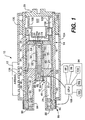
- Fig. 1 is a sectional view of a "smart" airbag inflator, partially in block diagram form, configured in accordance with a presently preferred embodiment of the present invention; and
- Fig. 2 is a side view of an injection port tube member utilized in the embodiment of Fig. 1.
-
- In accordance with the present invention, and as embodied herein, an airbag apparatus, generally indicated at 10, comprises an inflator, generally indicated at 14, for inflating an
airbag 12 in response to a vehicle accident.Inflator 14 includes acylindrical housing 16 closed off at its left end by a rear closure, generally indicated at 18, and at its right end by afront endwall 20. Therear closure 18 includes anannular wall 21 integrally formed with a forwardly extendingtube 22, and a rearwardly extendingannular chamber 24. Therear closure 18 andfront endwall 20 are fixed in place by suitable means, such as welded joints, to prevent fluid leakage. - The
cylindrical housing 16 is machined to provide a stepped bore for receiving a piston, generally indicated at 30, which includes aradial piston head 32 and a rearwardly extendingskirt 34 slidingly received inhousing bore 28. Thepiston skirt 34 is terminated in anannular piston head 36 that is slidingly received betweenhousing bore 38 and an outercylindrical wall 40 ofrear closure 18. Thisannular piston head 36 operates in anannular chamber 46 and is sealed against fluid leakage by suitable means, such as 0-rings 42, 44. -
Radial piston head 32 divides the interior portion ofcylindrical housing 16 defined bybore 28 into acombustion chamber 48 and anannular reservoir 49 containingliquid propellant 50. As disclosed in U.S. Patent No. 5,060,973 to Giovanetti and U.S. Patent No. 5,487,561 to Mandzy et al., which are herein incorporated by reference, the liquid propellant may be a hydroxyl ammonium nitrate-based liquid monopropellant. A particular suitable propellant composition comprises, by mass, approximately 60% hydroxyl ammonium nitrate (HAN) as an oxidizer, 20% triethyl ammonium nitrate (TEAN) as a fuel, and 20% water as a diluent. - A
central injection port 51, drilled axially through thepiston head 32, is normally closed by aterminal portion 54 oftube 22, which serves as a needle valve element. Thus,terminal portion 54 is slidingly received ininjection port 51 and is machined with an annular groove accommodating an O-ring 54a, to provide a fluid seal with the injection port sidewall. As seen in Fig. 2, at least a pair of diametrically opposed,longitudinal grooves 52 are cut in the peripheral surface oftube 22, beginning an appropriate distance rearwardly ofinjection port 51 and extending back toannular wall 21. Also as seen in Fig. 2, at least one additionallongitudinal groove 56 is cut in the tube peripheral surface, beginning at O-ring 54a and extending rearwardly toannular wall 21. - Seated in the shouldered central opening of
annular wall 21 is asquib 62, which is held in place by asnap ring retainer 66 andannular plug 68. The interior oftube 22 forwardly ofsquib 62 stores a solid propellant booster charge 72. This booster charge 72 may be boron potassium nitrate, which is ignited by electrically initiated detonation of thesquib 62. The byproducts of the booster chargecombustion exit tube 22 through anopening 74 interminal portion 54, which is normally closed by afrangible seal 76. - When
squib 62 is fired to ignite the booster charger 72,seal 76 is ruptured, and combustion gases flow intocombustion chamber 48, which is then pressurized. To permit initial rearward movement ofpiston 30 sufficient to open the forward end ofgroove 56 to thecombustion chamber 48, an appropriate volume of a compressible fluid, such as air, is included inliquid propellant reservoir 49. The communication then created betweenliquid propellant reservoir 49 and thecombustion chamber 48 throughgroove 56 allowsliquid propellant 50 to flow into thecombustion chamber 48 for combustion. Due to the differences in the surface areas of thepiston head 32 facing thereservoir 49 and the piston head surface facing thecombustion chamber 48 resulting from the presence of thecylindrical skirt 34, the fluid pressure in thereservoir 49 always exceeds the fluid pressure in thecombustion chamber 48. Consequently, regenerative pumping of the liquid propellant from thereservoir 49 into thecombustion chamber 48 is achieved. Aspiston 30 progresses through its rearward stroke,grooves 52 open intocombustion chamber 48, thereby increasing the opening area ofinjection port 51, and the injection rate of liquid propellant into thecombustion chamber 48 increases accordingly. Liquid propellant injection into thecombustion chamber 48 by regenerative pumping and its combustion continues untilpiston head 32 bottoms out againstannular wall 21, at which point the entire volume of liquid propellant has been pumped fromreservoir 49 into thecombustion chamber 48 and combusted to complete airbag deployment. -
Chamber 24 provided between outercylindrical wall 40 and innercylindrical wall 41 ofclosure 18 slidingly receives anannular piston 80. The forward end ofchamber 24 is vented to the atmosphere, as indicated at 81.Inner cylinder wall 41 ofclosure 18 extends rearwardly to mount acollar 88, which, in turn, mounts anannular electromagnet 86.Field piece 90 of this electromagnet, together withcollar 88, innercylindrical wall 41, andpiston 80, define anannular chamber 84, which communicates withannular chamber 46 through a plurality of orifices or a single annular orifice indicated at 92. - In accordance with a feature of the present invention,
chambers rheological fluid 83. Magneto-rheological fluids, such as carbonyl iron particles suspended in silicone oil, as disclosed in U.S. Patent No. 5,284,330 to Carlson et al., have a unique property in that viscosity can be controlled by a magnetic field. - As can be seen in Fig. 1, as
piston 30 strokes rearwardly to pumpliquid propellant 50 intocombustion chamber 48 for combustion,piston head 36 is also driven rearwardly throughchamber 46. Magneto-rheological fluid 83 is thus forced to flow throughorifices 92 fromchamber 46 intochamber 84, andpiston 80 is driven forwardly through chamber 82, which serves as a containment reservoir for thefluid 83. By controlling the viscosity offluid 83 and thus its rate of flow throughorifices 92 using a controllable magnetic field produced byelectromagnet 86, a variable retarding force can be exerted on the rearward stroke ofpiston 30. Since the rate of rearward stroke ofpiston 30 governs the liquid propellant combustion rate, and, in turn, airbag inflation rate, the magnitude of the magnetic field produced byelectromagnet 86 can be advantageously utilized to control airbag inflation rate on a real time basis. Thus, if no current is applied toelectromagnet 86, the viscosity ofdamper fluid 83 is at its lowest value and the airbag inflation is at a maximum rate. When current is applied to theelectromagnet 86 to produce a high magnetic field, piston stroke can be dramatically retarded to produce a gentle airbag deployment. In fact, a magnetic field of maximum magnitude can actually stop the flow of damper fluid throughorifices 92, which will arrest the rearward stroke ofpiston 30 and thus stop further airbag inflation. Between no magnetic field and maximum magnetic field are an infinite number of airbag inflation profiles that can be produced by real time variations of the magnetic field during an inflation period. - Further in accordance with the present invention, the magnetic field produced by
electromagnet 86 is varied in response to signals produced by asensor suite 94, including, for example, acrash severity sensor 96, a rear-facinginfant seat sensor 98, anoccupant weight sensor 100, adashboard proximity sensor 102, and aseat belt sensor 104, etc. Acentral processing unit 106 processes the sensor outputs according to an appropriate algorithm, such as to modulate the airbag inflation rate during deployment according to a particular scenario of collision and occupant parameters. - Completing the description of
inflator 10, a generally cup-shapedpartition 108 is inserted intohousing 16 in press-fit relation, with its open end dosed by front endwall 20 and its closed end portion defining aforward boundary 110 forcombustion chamber 48. Aconvoluted sleeve 112 serves to retain the position ofpartition 108 in the manner described in commonly assigned, copending application Serial No. 08/800,189, the disclosure of which is incorporated herein by reference. - The interior of cup-shaped
partition 108 provides aswirl chamber 122 in fluid communication withcombustion chamber 48 through a plurality of equiangularly spacedswirl ports 124 inpartition wall section 110. The term "swirl" is intended to characterizeports 124 as being configured to achieve a circular or swirling flow of fluid (combustion gases) inchamber 122 upon entry fromcombustion chamber 48. For this purpose,ports 124 may be drilled throughpartition wall section 110 at an oblique angle such that gases enterchamber 122 closely tangential to the inner cylindrical surface of thepartition wall section 110. The benefits achieved by utilization ofswirl ports 124 are discussed in the cited application Serial No. 08/800,189. - From
swirl chamber 122, gas flow is through equiangularly spacedswirl ports 126 inpartition wall section 108 into anannular chamber 128.Swirl ports 130 incylindrical wall 16 permit gas flow fromannular chamber 128 into anannular plenum chamber 132 provided between an outercylindrical shell 134 andcylindrical wall 16. Preferably, aring 135 of porous media of suitable heat exchanging material, such as braided steel mesh screens, is positioned inplenum chamber 132, which the gases flow through and are cooled en route to a plurality of vent holes 136 inshell 134 leading to theairbag 12. - It will be apparent to those skilled in the art that various modifications and variations may be made to the vehicle occupant restraint apparatus of the present invention without departing from the spirt of the invention. For example, the damper fluid may comprise an electro-rheological fluid whose viscosity is controlled by an electric field to vary flow rate through
orifice 92 and thus the damping force exerted against the rearward stroke ofregenerative pumping piston 30. It will also occur to those skilled in the art that, rather than a rheological hydraulic fluid, the desired modulated damping of the piston's regenerative pumping stroke could be achieved by varying the opening area oforifice 92, such as to vary the flow rate of a conventional hydraulic damping fluid through the orifice. Thus, it is intended that the scope of the present invention cover modifications and variations thereof, provided they come within the spirt of the appended claims .
Claims (17)
- An airbag inflator comprising:a housing (16);a combustion chamber (48) provided in the housing (16);a reservoir (49) provided in the housing (16) for containing a liquid propellant (50);a piston (30) slidingly received in the housing (16) and having a first piston head (32) separating the combustion chamber (48) from the liquid propellant reservoir (49);an injection port (51);a pyrotechnic initiator (62), detonated in response to a vehicle accident, to pressurize the combustion chamber (48) and to ignite liquid propellant injected into the combustion chamber (48) from the reservoir (49) through the injection port (51) during a regenerative pumping stroke of the piston (30), combustion of the injected liquid propellant producing airbag inflation gases; and characterized by:a controller (106) including rheological fluid and a hydraulic damper for exerting a variable retarding force on the piston's regenerative pumping stroke according to at least one accident parameter, thereby regulating a rate of airbag inflation during airbag deployment.
- The airbag inflator of claim 1, wherein the hydraulic damper includes a damping chamber (46) containing the rheological fluid (83), and the piston (30) includes a second piston head (36) slidingly received in the damping chamber (46).
- The airbag inflator of claim 2, wherein the damping chamber (46) further includes an orifice (92) through which the rheological fluid (83) is expelled by the second piston head (36) during the piston's regenerative pumping stroke, the controller (106) acting to adjustably control a rate of rheological fluid flow through the orifice (92).
- The airbag inflator of claim 3, wherein the rheological fluid (83) is a magneto-rheological fluid.
- The airbag inflator of claim 3, wherein the rheological fluid (83) is a magneto-rheological fluid, and the controller (106) further includes an electromagnet (86) for generating a magnetic field to vary a viscosity of the magneto-rheological fluid flow through the orifice (92).
- The airbag inflator of claim 5, wherein the controller (106) further includes;a plurality of sensors (94, 96, 98, 100, 102) for generating signals respectively indicative of occupant and collision parameters, anda central processing unit for processing the sensor signals to variably modulate current excitation of the electromagnet (86).
- The airbag inflator of claim 5, further including a containment chamber (24) for recovering the magneto-rheological fluid (83) expelled through the orifice (92).
- The airbag inflator of claim 7, wherein the damping and containment chambers (46, 24) are concentrically arranged in the housing (16), and the second piston head (36) is of an annular configuration and connected to the first piston head (32) by a cylindrical skirt (34).
- The airbag inflator of claim 8, wherein the containment chamber (24) includes a vent (81) open to atmospheric pressure, and an annular piston (80) slidingly received in the containment chamber (24) between the orifice (92) and the vent (81).
- The apparatus of any preceding claim, wherein the injection port (51) is defined in part by a hole through the first piston head (32).
- The apparatus of claim 10, wherein the injection port (51) is further defined by a forwardly extending needle valve element (54, 22) projecting through the hole to control an opening area of the injection port (51).
- The apparatus of claim 11, wherein the needle valve element (54,22) includes a terminal portion (54) disposed in fluid-sealing relation with the hole prior to detonation of the pyrotechnic initiator.
- The apparatus of claim 12, wherein the needle valve element (54, 22) includes angularly spaced, longitudinally extending, peripheral surface grooves (52) defining a differential opening area of the injection port (51) during the regenerative pumping stroke of the piston (30).
- The apparatus of claim 13, wherein the needle valve element (54, 22) is of a tubular shape accommodating a squib (62) at a rearward end and a forwardly extending cavity accommodating a booster charge (72) of the pyrotechnic initiator, the terminal portion of the needle valve element including an opening from the booster charge cavity into the combustion chamber, the opening normally closed by a frangible seal (76).
- The airbag inflator of claim 1, wherein the controller (106) acts to vary a viscosity of the rheological fluid (83).
- The airbag inflator of claim 15, wherein the damping chamber (46) includes an orifice (92) through which the rheological fluid is pumped by the piston pumping stroke at a rate determined by the rheological fluid viscosity.
- An occupant restraint apparatus for installation in a vehicle, comprising:an airbag (12); andan airbag inflator according to any preceding claim.
Applications Claiming Priority (5)
| Application Number | Priority Date | Filing Date | Title |
|---|---|---|---|
| US3723497P | 1997-02-03 | 1997-02-03 | |
| US37234P | 1997-02-03 | ||
| US995419 | 1997-12-19 | ||
| US08/995,419 US6036226A (en) | 1997-02-03 | 1997-12-19 | Inflator capable of modulation air bag inflation rate in a vehicle occupant restraint apparatus |
| PCT/US1998/001800 WO1998033684A1 (en) | 1997-02-03 | 1998-02-02 | Inflator capable of modulating airbag inflation rate in a vehicle occupant restraint apparatus |
Publications (3)
| Publication Number | Publication Date |
|---|---|
| EP0961719A1 EP0961719A1 (en) | 1999-12-08 |
| EP0961719A4 EP0961719A4 (en) | 2002-10-30 |
| EP0961719B1 true EP0961719B1 (en) | 2005-05-11 |
Family
ID=26713940
Family Applications (1)
| Application Number | Title | Priority Date | Filing Date |
|---|---|---|---|
| EP98907349A Expired - Lifetime EP0961719B1 (en) | 1997-02-03 | 1998-02-02 | Inflator capable of modulating airbag inflation rate in a vehicle occupant restraint apparatus |
Country Status (7)
| Country | Link |
|---|---|
| US (1) | US6036226A (en) |
| EP (1) | EP0961719B1 (en) |
| JP (1) | JP2001510420A (en) |
| KR (1) | KR20000070667A (en) |
| CA (1) | CA2279410C (en) |
| DE (1) | DE69830147T2 (en) |
| WO (1) | WO1998033684A1 (en) |
Families Citing this family (37)
| Publication number | Priority date | Publication date | Assignee | Title |
|---|---|---|---|---|
| DE29813961U1 (en) * | 1998-08-04 | 1998-12-10 | TRW Airbag Systems GmbH & Co. KG, 84544 Aschau | Gas generator with controllable liquid injection |
| EP0978424B1 (en) * | 1998-08-04 | 2003-06-18 | TRW Airbag Systems GmbH | Gas generator with controlable liquid injection |
| DE29821232U1 (en) | 1998-11-26 | 1999-04-01 | TRW Airbag Systems GmbH & Co. KG, 84544 Aschau | Gas generator for a security system |
| LU90358B1 (en) * | 1999-03-01 | 2000-09-05 | Iee Sarl | Device for stopping the expansion of an airbag in a vehicle |
| US6398590B2 (en) | 2000-07-11 | 2002-06-04 | Tyco Electronics Corporation | Nonpolarized electrical connector assembly especially for use as automotive squib connector |
| DE10062756A1 (en) * | 2000-12-15 | 2002-06-20 | Conti Temic Microelectronic | Circuit arrangement for controlling a gas generator of an occupant protection device which can be influenced by a magnetic field in the course of the ignition |
| US6394048B1 (en) * | 2001-01-16 | 2002-05-28 | Ford Global Technologies, Inc. | Variable compression ratio internal combustion engine using field-sensitive fluid |
| US6692022B2 (en) * | 2001-07-14 | 2004-02-17 | Delphi Technologies, Inc. | Active venting of an airbag module |
| US6609931B2 (en) | 2001-10-25 | 2003-08-26 | Tyco Electronics Corp. | Orientationless squib connector assembly |
| GB0201069D0 (en) * | 2002-01-17 | 2002-03-06 | Dalphimetal Ltd | Valve for controlling inflation and venting of an airbag |
| US7428922B2 (en) * | 2002-03-01 | 2008-09-30 | Halliburton Energy Services | Valve and position control using magnetorheological fluids |
| US7670623B2 (en) * | 2002-05-31 | 2010-03-02 | Materials Modification, Inc. | Hemostatic composition |
| US6789820B2 (en) | 2002-06-26 | 2004-09-14 | Trw Vehicle Safety Systems Inc. | Variable output inflator |
| US6871871B2 (en) | 2002-09-13 | 2005-03-29 | Island Pyrochemical Industries Corp. | Air bag inflator |
| US6889613B2 (en) * | 2002-09-13 | 2005-05-10 | Island Pyrochemical Industries Corp. | Variable output inflator |
| US6889614B2 (en) * | 2002-09-13 | 2005-05-10 | Island Pyrochemical Industries Corp. | Air bag inflator |
| US6786508B2 (en) | 2002-09-30 | 2004-09-07 | Lear Corporation | Occupant protection apparatus for a vehicle |
| US7560160B2 (en) * | 2002-11-25 | 2009-07-14 | Materials Modification, Inc. | Multifunctional particulate material, fluid, and composition |
| US7046167B2 (en) * | 2002-12-13 | 2006-05-16 | Ford Global Technologies, Llc | Adaptive collision load path modification system for vehicle collision compatibility |
| US7007972B1 (en) | 2003-03-10 | 2006-03-07 | Materials Modification, Inc. | Method and airbag inflation apparatus employing magnetic fluid |
| US6982501B1 (en) | 2003-05-19 | 2006-01-03 | Materials Modification, Inc. | Magnetic fluid power generator device and method for generating power |
| DE10323524B4 (en) * | 2003-05-24 | 2014-11-27 | GM Global Technology Operations LLC (n. d. Ges. d. Staates Delaware) | Restraint system for vehicle occupants of a motor vehicle |
| US6913285B2 (en) * | 2003-05-28 | 2005-07-05 | Autoliv Asp, Inc. | Adaptive inflation performance using magnetic characteristics of gases |
| US6910699B2 (en) * | 2003-05-30 | 2005-06-28 | Deere & Company | Magnetorheological fluid brake and force-feedback system for a steering mechanism |
| US7200956B1 (en) | 2003-07-23 | 2007-04-10 | Materials Modification, Inc. | Magnetic fluid cushioning device for a footwear or shoe |
| ATE338661T1 (en) * | 2003-10-08 | 2006-09-15 | Island Pyrochemical Ind Corp | INFLATION DEVICE WITH VARIABLE OUTPUT |
| EP1522468B1 (en) * | 2003-10-08 | 2007-02-07 | Island Pyrochemical Industries Corp. | Air bag inflator and injection piston assembly |
| EP1522469A1 (en) * | 2003-10-08 | 2005-04-13 | Island Pyrochemical Industries Corp. | Air bag inflator |
| US7448389B1 (en) | 2003-10-10 | 2008-11-11 | Materials Modification, Inc. | Method and kit for inducing hypoxia in tumors through the use of a magnetic fluid |
| US7125042B2 (en) * | 2004-03-25 | 2006-10-24 | Automotive Systems Laboratory, Inc. | Inflator using reversing axial flow |
| JP3828904B2 (en) * | 2004-06-14 | 2006-10-04 | 本田技研工業株式会社 | Air bag inflator performance test equipment |
| US20060202454A1 (en) | 2005-03-08 | 2006-09-14 | Amnon Parizal | Airbag assembly and modulated airbag inflation process |
| US7464961B2 (en) | 2006-06-14 | 2008-12-16 | Island Pyrochemical Industries Corp. | Variable output inflator |
| EP2085269A1 (en) | 2008-02-04 | 2009-08-05 | Island Pyrochemical Industries Corporation | Electronically controlled safety restraint system |
| US8764054B2 (en) * | 2009-02-04 | 2014-07-01 | Tk Holdings Inc. | Gas generating system |
| US9457761B2 (en) * | 2014-05-28 | 2016-10-04 | Raytheon Company | Electrically controlled variable force deployment airbag and inflation |
| KR102537110B1 (en) * | 2021-08-23 | 2023-05-26 | 부산대학교 산학협력단 | Pneumatic airbag deployment device using electromagnetic force |
Family Cites Families (28)
| Publication number | Priority date | Publication date | Assignee | Title |
|---|---|---|---|---|
| US4907486A (en) * | 1977-10-06 | 1990-03-13 | General Electric Company | Liquid propellant gun |
| US4341147A (en) * | 1980-06-16 | 1982-07-27 | General Electric Company | Coaxial dual hollow piston regenerative liquid propellant gun |
| US4523508A (en) * | 1983-11-02 | 1985-06-18 | General Electric Company | In-line annular piston fixed bolt regenerative liquid propellant gun |
| US4523507A (en) * | 1983-11-02 | 1985-06-18 | General Electric Company | In-line annular piston fixed bolt regenerative liquid propellant gun |
| US4693165A (en) * | 1986-06-27 | 1987-09-15 | General Electric Company | Liquid propellant gun |
| US4745841A (en) * | 1986-06-27 | 1988-05-24 | General Electric Company | Liquid propellant gun |
| US5060973A (en) * | 1990-07-23 | 1991-10-29 | General Electric Company | Liquid propellant inflator for vehicle occupant restraint apparatus |
| DE4135547A1 (en) * | 1991-10-28 | 1993-04-29 | Dynamit Nobel Ag | GAS GENERATOR, IN PARTICULAR FOR AN INFLATABLE IMPACT CUSHION TO PROTECT A MOTOR VEHICLE INJURY FROM INJURY |
| US5284330A (en) * | 1992-06-18 | 1994-02-08 | Lord Corporation | Magnetorheological fluid devices |
| US5414845A (en) * | 1992-06-26 | 1995-05-09 | International Business Machines Corporation | Network-based computer system with improved network scheduling system |
| US5695216A (en) * | 1993-09-28 | 1997-12-09 | Bofors Explosives Ab | Airbag device and propellant for airbags |
| US5487561A (en) * | 1994-12-09 | 1996-01-30 | Martin Marietta Corporation | Safety bag inflation apparatus using a liquid propellant gas generator |
| WO1997006982A1 (en) * | 1995-08-12 | 1997-02-27 | Temic Bayern-Chemie Airbag Gmbh | Method and airbag system for decreasing the kinetic energy of a vehicle occupant |
| DE19610299B4 (en) * | 1996-03-15 | 2006-07-06 | Audi Ag | Safety device with a controllable gas generator for a motor vehicle |
| US5683104A (en) * | 1996-03-22 | 1997-11-04 | Morton International, Inc. | Combustion moderation in an airbag inflator |
| US5639117A (en) * | 1996-06-05 | 1997-06-17 | Lockheed Martin Corporation | Vehicle occupant restraint apparatus |
| EP0812969B1 (en) * | 1996-06-12 | 2003-11-19 | Ardmac Technology Limited | Sterile room structures |
| US5907120A (en) * | 1996-06-17 | 1999-05-25 | Hi Shear Technology Corporation | Inflator for vehicle air bags |
| US5713596A (en) * | 1996-07-01 | 1998-02-03 | Lockheed Martin Corporation | Liquid propellant inflation apparatus for deploying an inflatable member |
| US5669631A (en) * | 1996-11-18 | 1997-09-23 | Morton International, Inc. | Liquid propellant airbag inflator with auto injection combustion chamber |
| US5719351A (en) * | 1996-12-03 | 1998-02-17 | Morton International, Inc. | Anti-rupture method for liquid propellant gas inflator |
| US5829784A (en) * | 1997-02-13 | 1998-11-03 | General Dynamics Armament Systems, Inc. | Airbag inflator for vehicle occupant restraint apparatus |
| US5806884A (en) * | 1997-02-18 | 1998-09-15 | Autoliv Asp, Inc. | Adaptive regenerative inflator |
| US5857699A (en) * | 1997-02-25 | 1999-01-12 | Autoliv Asp, Inc. | Adaptive output fluid fueled airbag inflator |
| FR2760710B1 (en) * | 1997-03-14 | 1999-04-23 | Livbag Snc | PYROTECHNICAL GAS GENERATOR WITH ADAPTABLE FLOW AND VOLUME FOR PROTECTIVE CUSHIONS |
| US5967550A (en) * | 1997-10-07 | 1999-10-19 | Trw Inc. | Staged pyrotechnic air bag inflator |
| US5927753A (en) * | 1997-12-15 | 1999-07-27 | Trw Vehicle Safety Systems Inc. | Vehicle occupant protection apparatus |
| US5947514A (en) * | 1998-02-20 | 1999-09-07 | Breed Automotive Technology, Inc. | Valve controlled automotive pyrotechnic systems |
-
1997
- 1997-12-19 US US08/995,419 patent/US6036226A/en not_active Expired - Lifetime
-
1998
- 1998-02-02 KR KR1019997006916A patent/KR20000070667A/en not_active Abandoned
- 1998-02-02 CA CA002279410A patent/CA2279410C/en not_active Expired - Fee Related
- 1998-02-02 WO PCT/US1998/001800 patent/WO1998033684A1/en not_active Ceased
- 1998-02-02 DE DE69830147T patent/DE69830147T2/en not_active Expired - Fee Related
- 1998-02-02 JP JP53309798A patent/JP2001510420A/en not_active Ceased
- 1998-02-02 EP EP98907349A patent/EP0961719B1/en not_active Expired - Lifetime
Also Published As
| Publication number | Publication date |
|---|---|
| WO1998033684A1 (en) | 1998-08-06 |
| CA2279410A1 (en) | 1998-08-06 |
| KR20000070667A (en) | 2000-11-25 |
| EP0961719A1 (en) | 1999-12-08 |
| EP0961719A4 (en) | 2002-10-30 |
| DE69830147D1 (en) | 2005-06-16 |
| US6036226A (en) | 2000-03-14 |
| CA2279410C (en) | 2005-11-08 |
| DE69830147T2 (en) | 2006-01-19 |
| JP2001510420A (en) | 2001-07-31 |
Similar Documents
| Publication | Publication Date | Title |
|---|---|---|
| US6036226A (en) | Inflator capable of modulation air bag inflation rate in a vehicle occupant restraint apparatus | |
| US6039347A (en) | Liquid propellant airbag inflator with dual telescoping pistons | |
| EP0842065B1 (en) | Vehicle occupant restraint apparatus | |
| US5829784A (en) | Airbag inflator for vehicle occupant restraint apparatus | |
| US5345876A (en) | Hybrid inflator | |
| US6543805B2 (en) | Dual stage air bag inflator | |
| EP1056624B2 (en) | Adaptive output inflator | |
| US6142515A (en) | Air bag inflator with heat sink and retainer | |
| US20020144621A1 (en) | Dual stage air bag inflator with secondary propellant cap | |
| WO2004033264A2 (en) | Dual stage inflator with extended gas delivery for a vehicular airbag system | |
| EP1613508B1 (en) | Belt and side impact inflator | |
| EP0843627B1 (en) | Liquid propellant inflation apparatus for deploying an inflatable member | |
| US20050029788A1 (en) | Inflator | |
| GB2281429A (en) | A gas generator for a vehicle safety system. | |
| KR100462918B1 (en) | Liquid Propellant Expansion Device for Expanding Expansion Members | |
| WO2000021800A9 (en) | Vortex valve inflator for inflatable restraint system | |
| KR19980021785U (en) | Car airbag device | |
| KR19980021626A (en) | Multi-stage Pullout Airbag Unit | |
| JPH0939709A (en) | Air bag device |
Legal Events
| Date | Code | Title | Description |
|---|---|---|---|
| PUAI | Public reference made under article 153(3) epc to a published international application that has entered the european phase |
Free format text: ORIGINAL CODE: 0009012 |
|
| 17P | Request for examination filed |
Effective date: 19990830 |
|
| AK | Designated contracting states |
Kind code of ref document: A1 Designated state(s): DE FR SE |
|
| A4 | Supplementary search report drawn up and despatched |
Effective date: 20020917 |
|
| AK | Designated contracting states |
Kind code of ref document: A4 Designated state(s): DE FR SE |
|
| RAP1 | Party data changed (applicant data changed or rights of an application transferred) |
Owner name: GENERAL DYNAMICS ARMAMENT AND TECHNICAL PRODUCTS, |
|
| 17Q | First examination report despatched |
Effective date: 20031211 |
|
| GRAP | Despatch of communication of intention to grant a patent |
Free format text: ORIGINAL CODE: EPIDOSNIGR1 |
|
| GRAS | Grant fee paid |
Free format text: ORIGINAL CODE: EPIDOSNIGR3 |
|
| GRAA | (expected) grant |
Free format text: ORIGINAL CODE: 0009210 |
|
| AK | Designated contracting states |
Kind code of ref document: B1 Designated state(s): DE FR SE |
|
| REF | Corresponds to: |
Ref document number: 69830147 Country of ref document: DE Date of ref document: 20050616 Kind code of ref document: P |
|
| REG | Reference to a national code |
Ref country code: SE Ref legal event code: TRGR |
|
| PG25 | Lapsed in a contracting state [announced via postgrant information from national office to epo] |
Ref country code: SE Free format text: LAPSE BECAUSE OF NON-PAYMENT OF DUE FEES Effective date: 20060203 |
|
| PLBE | No opposition filed within time limit |
Free format text: ORIGINAL CODE: 0009261 |
|
| STAA | Information on the status of an ep patent application or granted ep patent |
Free format text: STATUS: NO OPPOSITION FILED WITHIN TIME LIMIT |
|
| ET | Fr: translation filed | ||
| 26N | No opposition filed |
Effective date: 20060214 |
|
| PG25 | Lapsed in a contracting state [announced via postgrant information from national office to epo] |
Ref country code: DE Free format text: LAPSE BECAUSE OF NON-PAYMENT OF DUE FEES Effective date: 20060901 |
|
| EUG | Se: european patent has lapsed | ||
| REG | Reference to a national code |
Ref country code: FR Ref legal event code: ST Effective date: 20061031 |
|
| PG25 | Lapsed in a contracting state [announced via postgrant information from national office to epo] |
Ref country code: FR Free format text: LAPSE BECAUSE OF NON-PAYMENT OF DUE FEES Effective date: 20060228 |