EP0960807B1 - Bicycle frame section comprising a brake mounting member - Google Patents
Bicycle frame section comprising a brake mounting member Download PDFInfo
- Publication number
- EP0960807B1 EP0960807B1 EP99110207A EP99110207A EP0960807B1 EP 0960807 B1 EP0960807 B1 EP 0960807B1 EP 99110207 A EP99110207 A EP 99110207A EP 99110207 A EP99110207 A EP 99110207A EP 0960807 B1 EP0960807 B1 EP 0960807B1
- Authority
- EP
- European Patent Office
- Prior art keywords
- brake
- bicycle
- frame
- members
- mounting
- Prior art date
- Legal status (The legal status is an assumption and is not a legal conclusion. Google has not performed a legal analysis and makes no representation as to the accuracy of the status listed.)
- Expired - Lifetime
Links
Images


Classifications
-
- B—PERFORMING OPERATIONS; TRANSPORTING
- B62—LAND VEHICLES FOR TRAVELLING OTHERWISE THAN ON RAILS
- B62L—BRAKES SPECIALLY ADAPTED FOR CYCLES
- B62L1/00—Brakes; Arrangements thereof
-
- B—PERFORMING OPERATIONS; TRANSPORTING
- B62—LAND VEHICLES FOR TRAVELLING OTHERWISE THAN ON RAILS
- B62L—BRAKES SPECIALLY ADAPTED FOR CYCLES
- B62L1/00—Brakes; Arrangements thereof
- B62L1/02—Brakes; Arrangements thereof in which cycle wheels are engaged by brake elements
- B62L1/06—Brakes; Arrangements thereof in which cycle wheels are engaged by brake elements the wheel rim being engaged
- B62L1/10—Brakes; Arrangements thereof in which cycle wheels are engaged by brake elements the wheel rim being engaged by the elements moving substantially parallel to the wheel axis
- B62L1/14—Brakes; Arrangements thereof in which cycle wheels are engaged by brake elements the wheel rim being engaged by the elements moving substantially parallel to the wheel axis the elements being mounted on levers pivotable about different axes
Definitions
- This invention relates to a bicycle frame section according to the preamble of claim 1 as disclosed in document US-A-4,008,903.
- Bicycling is becoming an increasingly more popular form of recreation as well as a means of transportation. Moreover, bicycling has also become a very popular competitive sport for both amateurs and professionals. Whether the bicycle is used for recreation, transportation or competition, the bicycle industry is constantly improving the various components of the bicycle.
- One particular component of bicycles which has been extensively redesigned over the past years is the bicycle brake device. Bicycle brake devices are constantly being redesigned to provide additional braking power.
- caliper brakes there are several types of bicycle brake devices which are currently available on the market. Examples of some types of common bicycle brake devices include rim brakes and caliper brakes. With respect to caliper brakes, there are mainly three types of caliper brakes: a side pull type, a center pull type and cantilever type.
- a side pull type of caliper brake device a pair of brake arms are pivotally connected together about a center mounting bolt which attaches to the frame of the bicycle.
- Each of the brake arms has a lever portion which is coupled to the brake wire such that when the rider operates the brake lever of the brake operating device, the lever portions of the brake arms are pulled together, which in turn move the brake shoes attached to the other ends of the brake arms together against the rim of the bicycle wheel.
- Return springs are provided for biasing the brake arms away from the bicycle wheel rim when the rider releases the brake lever.
- Side pull types of caliper brake devices are commonly used in road bikes.
- a center pull type of caliper brake device operates similar to the side pull type, except that the brake arms are typically attached to a brake arm bridge such that each brake arm is pivotally coupled at a separate pivot point on the brake arm bridge.
- the brake arm bridge is attached directly to the frame of the bicycle.
- a straddle cable interconnects the two lever portions of the brake arms such that a main brake wire, which is coupled to the straddle wire, pulls the lever portions of the brake arms together.
- a cantilever type of caliper brake device is generally mounted on bicycles designed for off road use such as mountain bikes (MTB) and all terrain bikes (ATB).
- a cantilever type brake device is designed to provide a powerful braking force.
- a cantilever type of brake device is equipped with a pair of brake arms which are rotatably supported in a cantilever fashion on the front or rear fork of the bicycle frame, with the brake shoes attached to the upper portions of the brake arms.
- the lower ends of the brake arms are rotatably supported on the bicycle frame and the upper ends are linked to a brake cable or wire.
- the brake shoes are arranged opposite one another on either side of the bicycle wheel rim which is located between the arms.
- Cantilever types of caliper brake devices have several advantages over side pull types of caliper brake devices. For example, with such a cantilever brake device, there is no need to vary the shape of the device with the size of the bicycle, as may be the case with a side pull type of caliper brake device. Moreover, cantilever type of caliper brake devices apply a more equal braking force than a side pull type caliper brake.
- a bicycle frame section which is made of a plastic material.
- the frame section is a one piece unitary member which includes ribs and profiles which are directed outwardly of the frame section.
- bearings are provided in mouldings which are integrally formed and moulded to the bicycle frame member, i.e. they are part of the bicycle frame member.
- the mouldings support opposite sides of a mounting portion of a bicycle brake device therebetween.
- the mouldings are integral parts of the bicycle frame there is no need for compensation of tolerances which might occur by welding two frame parts together or due to inaccuracies during the production to different frame models.
- the brake mounting members can not be adadpted to various kinds of configurations of frame members and can not be used for adjusting the brake to different wheels, i.e. adjusting the longitudinal position o the brake mounting members with respect to the frame members.
- a bicycle frame section as defined in claim 1 is provided.
- Still another object of the present invention is to provide a bicycle frame section which can be manufactured using conventional manufacturing methods.
- a bicycle frame section comprising a first frame member, the first frame member being arranged on the left or the right side of the bicycle frame, a second frame member spaced from said first frame member, the second frame member being arranged on the same side of the bicycle frame as the first frame member, a first brake mounting member coupled to said first frame member and a second brake mounting member coupled to said second frame member, said first and second brake mounting members being configured to support opposite sides of a mounting portion of a bicycle brake device therebetween and said first and second brake mounting members are formed as separate parts with regard to said first and second frame members.
- a bicycle frame section comprising a first rigid frame member; a second rigid frame member spaced from the first rigid frame member; a first brake mounting member coupled to the first rigid frame member; and a second brake mounting member coupled to the second rigid frame member, the first and second brake mounting members being configured to support opposite sides of a mounting portion of a bicycle brake device therebetween.
- a bicycle frame section comprising bicycle frame means for supporting a part of a bicycle, the bicycle frame means having first and second frame members spaced apart from each other, first brake mounting means, coupled to the first frame member, for supporting a first end of a mounting member of a brake arm; and second brake mounting means, coupled to the second frame member, for supporting a second end of the mounting member of a brake arm.
- a bicycle frame section comprising a first brake mounting member adapted to be coupled to a bicycle frame, a second brake mounting member adapted to be coupled to the bicycle frame; and a connecting member coupled between the first and second mounting members to form a brake device receiving recess therebetween.
- Bicycle frame 12 has a pair of bicycle brake devices 14 fixedly coupled to frame 12 via brake mounting structures 15 in accordance with a first embodiment of the present invention. While a MTB style bicycle is illustrated, it will be apparent to those skilled in the art from this disclosure that the present invention can be used with other styles of bicycles without departing from the scope of the present invention.
- bicycle frame 12 has a main bicycle frame body 16, which constitutes the skeleton of the bicycle body.
- Bicycle frame body 16 is generally constructed of rigid tubular frame sections or members which are rigidly coupled together by welding or any other conventional method.
- the tubular frame members can be constructed of any suitable rigid material such as aluminum, titanium, etc.
- Bicycle frame 12 also has a front fork 18 constructed mainly of rigid tubular frame members which are rigidly coupled together by welding or any other conventional method. Front fork 18 is rotatably supported by frame body 16 to rotate about an inclined vertical axle in the front portion of frame body 16.
- the bicycle 10 further comprises a handlebar 20 that is fixedly coupled to the front fork 18, a drive train 21 that is attached to the lower portion of the frame body 16 for converting a pedaling force to drive force, a front wheel 22 that is rotatably supported at the lower end of the front fork 18, a rear wheel 23 that is rotatably supported in the back portion of the frame body 16, and front and back braking devices 14.
- the front fork 18 is rotatably coupled at its upper end to frame body 16 and has a bifurcated lower portion for receiving a front wheel 22 therebetween ( Figure 1).
- the front fork 18 has two pairs of rigid tubular frame members 24 with their upper ends coupled together by an intermediate or connecting member 26 and their lower ends joined together by a pair of front wheel mounting ends or plates 27.
- Each of the front wheel mounting ends or plates 27 has an open ended slot 28 for fixedly receiving the axle of the front hub of wheel 22 in a conventional manner.
- the front bicycle brake device 14 is fixedly coupled to front fork 18 via a pair of brake mounting structures 15.
- Each of the brake mounting structures 15 is rigidly and fixedly coupled to a pair of adjacent frame members 24.
- brake mounting structures 15 are welded between frame members 24.
- Brake mounting structures 15 are shown in Figures 6 and 7 and discussed in detail below.
- the handlebar 20 has a handlebar stem adjustably coupled to the top portion of the front fork 18 for adjusting the height of the handlebar, and a pair of handle portions extending to the right and left from the top end of the handlebar stem. Grips (only one shown) are fitted on the two ends of the handle portions of the handlebar 20. Brake levers 29 (only one shown) and shifting levers 30 (only one shown) are located adjacent to these grips in a conventional manner. The general construction and operation of brake levers 29 and shifting levers 30 are generally old and well known, and thus, they will not be discussed or illustrated in detail herein.
- the frame body 16 is a diamond shaped frame with a front triangle and a back triangle located behind the front triangle.
- the front triangle comprises a horizontally disposed top tube 31, an angled down tube 32 that is located beneath the top tube 31 and that rises toward the front, a head tube 33 for joining the front ends of the top tube 31 and the down tube 32, and a seat tube 34 that rises at an angle and joins the back ends of the top tube 31 and the down tube 32.
- a bottom bracket shell 35 is formed at the joint between the seat tube 34 and the down tube 32.
- a seat post 36 equipped with a saddle 37 is slideably coupled to the seat tube 34 for vertically adjusting the position of the seat post 36 and saddle 37.
- the back triangle comprises a rear or back fork 40 having a seat stay 41 rigidly coupled to seat tube 34 and a chain stay 42 rigidly coupled to bottom bracket shell 35.
- the seat stay 41 has four rigid tubular frame members 43 with the front ends of each tubular frame members 43 rigidly coupled to seat tube 34.
- the tubular frame members 43 extend downwardly from seat tube 34 in a bifurcated manner for receiving rear wheel 23 therebetween.
- a pair of tubular frame members 43 are located on each side of rear wheel 23.
- the rear ends of adjacent tubular frame members 43 are each interconnected together by a rear fork mounting end or plate 44.
- Each of the rear fork mounting ends or plates 44 has an open ended slot 45 for fixedly receiving the axle of the rear hub in a conventional manner.
- the rear bicycle brake device 14 of the first embodiment is also fixedly coupled to the seat stay 41 via a pair of brake mounting structures 15.
- the front and rear bicycle brake devices 14 are fixedly coupled to frame 12 in substantially the same manner, except for different frame members.
- Each of the brake mounting structures 15 of the rear bicycle brake device 14 is rigidly and fixedly coupled to a pair of adjacent frame members 43.
- brake mounting structures 15 of the rear bicycle brake device 14 are welded to a pair of adjacent frame members 43 as seen in Figure 5.
- chain stay 42 has a pair of rigid tubular frame members 46 with one of the frame members 46 located on each side of wheel rear 23.
- Chain stay 42 has the front ends of tubular frame members 46 rigidly coupled to bottom bracket shell 35 as seen in Figure 1.
- the tubular frame members 46 extend backward from bottom bracket shell 35 where they are joined at their back ends by the rear fork mounting ends or plates 44.
- the drive train 21 basically comprises a front chainwheel and crank assembly 54 coupled to the bottom bracket shell 35, a set of rear chainwheels or sprockets 55 non-rotatably attached to the free hub of rear wheel 23, a chain 56 that passes over the front chainwheel and crank assembly 54 and rear chainwheels 55, and passes through front and rear deraille 57 and 58 for shifting gears in a conventional manner via shifting levers 30.
- chainwheel and crank assembly 54 comprises a bottom bracket (not shown), right and left crank arms 59, with pedals 60 attached to the tip of each crank arm 59.
- the bottom bracket connects right and left crank arms 59 together.
- a spindle is rotatably supported by the bottom bracket which in turn is mounted in bottom bracket shell 35 of frame body 16 in a conventional manner.
- front bicycle brake device 14 is coupled to front fork 18 for engaging and applying a braking force against the rim of front bicycle wheel 22.
- rear bicycle brake device 14 is coupled to rear fork 40 for engaging and applying a braking force against the rim of rear bicycle wheel 23.
- bicycle brake devices 14 are illustrated as cantilever brake devices.
- Brake devices 14 have an increased braking force over prior art brake devices in that the brake devices 14 are pivotally supported by mounting structures 15 as discussed below.
- Bicycle brake devices 14 are operated in a substantially conventional manner by the rider via conventional brake operating devices or levers 29 which are mounted on handle bar 20 of bicycle 10 in a conventional manner.
- Bicycles and their various components are well-known in the prior art, and thus, bicycle 10 and its various components will not be discussed or illustrated in detail herein.
- brake devices 14 are operatively coupled to brake operating devices 29 via conventional brake cables 62, each having an inner brake wire 63 and an outer casing 64.
- the rider operates one or both of the brake operating devices 29 to cause one or both of the brake devices 14 to move inwardly for applying a braking force against the rim of one or both of the bicycle wheels 22 and/or 23.
- brake devices 14 Upon release of the brake operating devices 29, brake devices 14 will release the rim to allow bicycle wheels 22 and 23 to freely rotate.
- each of the brake devices 14 basically includes a pair of brake mechanisms 70a and 70b which are substantially mirror images of each other, except for their connections to brake cable 62.
- right brake mechanism 70a basically includes a mounting assembly 71 a, a brake arm 72a, a return spring 73a, and a brake shoe 75a
- left brake mechanism 70b basically includes a mounting assembly 71b, a brake arm 72b, a return spring 73b and a brake shoe 75b.
- Mounting assemblies 71a and 71b are fixedly coupled to brake mounting structures 15 for fixedly coupling brake device 14 to the tubular frame members of frame 12.
- Brake arms 72a and 72b are preferably constructed of a suitable rigid material.
- the brake arms can be cast or machined from any suitable material such as aluminum, titanium, dense plastic, ceramic, acrylic, etc.
- brake arms 72a and 72b are constructed of a lightweight material to minimize the weight of brake devices 14.
- Brake arms 72a and 72b are substantially identical to each other, except that their upper ends are slightly modified for accommodating conventional cable connections or wire mounting portions as seen in Figures 2 and 4.
- Brake arms 72a and 72b are pivotally coupled to mounting assemblies 71 a and 71b, respectively, for movement between a release position and a braking position.
- Return springs 73a and 73b are coupled between mounting assemblies 71a and 71b and brake aims 72a and 72b, respectively, for pivotally biasing brake aims 72a and 72b to their release positions.
- Brake shoes 75a and 75b are fixedly coupled to shoe attachment portions 74a and 74b of brake anus 72a and 72b, respectively.
- Each of the mounting assemblies 71 a and 71b are basically identical and include a mounting or pivot pin 80 and a bushing arrangement 81.
- the mounting or pivot pins 80 are each preferably constructed of two pieces, e.g., a bolt 82 and an internally threaded sleeve 83.
- the bushing arrangements 81 surround pivot pins 80 and are fixedly secured to mounting structures 15 via engagement pins 84 as seen in Figure 6. Since pivot pins 80 and bushing arrangements 81 are well-known in the art, they will not be discussed in detail herein.
- Brake arms 72a and 72b have their upper portions 85a and 85b coupled to brake cable 62 for moving brake arms 72a and 72b from a release position to a braking position.
- upper portion 84a of brake arm 72a is coupled to inner brake wire 63 of brake cable 62 via lock bolt 87 which is received into a threaded hole.
- Lock bolt 87 clamps inner brake wire 63 against upper portion 85a of brake arm 72a.
- the outer casing 64 of brake cable 62 is coupled to upper portion 85b of brake arm 72b by connecting arm 86.
- connecting aim 86 is pivotally coupled to upper portion 85b of brake arm 72b and outer casing 64 of brake cable 62.
- Application of brake operating device 29 causes upper portions 85a and 85b to move inwardly towards each other and the friction pads of brake shoes 75a and/or 75b to engage the rim of the wheels 22 and/or 23.
- shoe attachment portions 74a and 74b integrally formed therewith.
- shoe attachment portions 74a and 74b can be pivotally coupled to brake arms 72a and 72b for attaching brake shoes 75a and 75b thereto in a conventional manner as known in the art.
- other types of shoe attachment portions can be utilized as needed and/or desired.
- brake arms 72a and 72b each have a hole for receiving one of the pivot pins 80 therethrough,
- the lower portions of brake arms 72a and 72b are pivotally coupled to mounting assemblies 71a and 71b such that brake arms 72a and 72b can rotate about the pivot axes formed by pivot pins 80.
- Return spring or biasing member 73a is fixedly coupled at one end to mounting assembly 71 via a fastener or screw in a conventional manner.
- Return spring 73a is designed to normally bias brake arm 72a in a clockwise direction as seen in Figures 2 and 4. Accordingly, brake arm 72a is biased by return spring 73a such that brake shoe 75a normally moves away from the rim of bicycle wheel 22 or 23.
- Return spring or biasing member 73b is similarly designed to normally bias brake arm 72b to a release position. Specifically, brake arm 72b is biased by return spring 73b in a counter-clockwise direction as seen in Figures 2 and 4. Accordingly, brake arm 72b is biased by return spring 73b such that brake shoe 75b normally moves away from the rim of bicycle wheel 22 or 23.
- Brake shoe 75a is attached to shoe attachment portion 74a such that brake shoe 75a can be adjusted vertically to ensure proper engagement between brake shoe 75a and the rim of bicycle wheel 22 or 23.
- brake shoe 75b is attached to shoe attachment portion 74b such that brake shoe 75b can be adjusted vertically to ensure proper engagement between brake shoe 75b and the rim of bicycle wheel 22 or 23.
- each bicycle brake mounting structure 15 has an intermediate connecting member 90 and a pair of brake mounting flanges 91 extending substantially perpendicular from opposite ends of an intermediate connecting member 90.
- An attachment flange 92 extends outwardly from each of the mounting flanges 91 for attaching mounting structure 15 to frame members 24 of front fork 18 as seen in Figure 6.
- a mounting recess 94 is formed between flanges 91 and 92 for receiving a tubular-frame member.
- brake mounting structure 15 is welded or otherwise rigidly and fixedly secured to the tubular frame members such that the tubular frame members are located within the recesses 94.
- Each of the brake mounting flanges 91 has a pivot mounting hole 95 for receiving one end of the pivot pin 80 for the brake arm.
- the pin mounting holes 95 are preferably axially aligned with one another.
- one of the mounting flanges 91 of each of the mounting structures 15 also has a smaller hole 96 for receiving one of the engagement pins 84 as seen in Figure 6 of the mounting assemblies 71a or 71b.
- the inner brake wire 63 of the brake cable 62 is relaxed so that the return springs 73a and 73b cause the brake arms 72a and 72b to pivot in their opening directions.
- the inner faces of the friction pads of brake shoes 75a and 75b are withdrawn from the side surfaces of the rim of the bicycle wheel 22 and/or 23 so that the braking action is released.
- FIG. 16 and 17 the rear fork portion 140' of a modified bicycle frame 12 is illustrated in accordance with a second embodiment of the present invention.
- This second embodiment differs from the first embodiment in that the chain stay 142 of frame 12 has been modified to support cantilever brake device 14.
- the first and second embodiment will be discussed and illustrated herein.
- the second embodiment utilizes many of the same parts of the first embodiment, these parts will be given the same reference numerals.
- the chain stay 142 is constructed of four tubular frame members 146 with the front end of each frame member 146 rigidly coupled to the bottom bracket shell 35 by welds.
- the rear ends of two adjacent frame members 146 are coupled together by wheel mounting ends or plates 144.
- the wheel mounting plates 144 have open ended slots 145 for receiving the axle of the rear hub.
- Adjacent pairs of the frame members 146 have mounting structures 15 fixedly coupled thereto for coupling brake device 14 thereto in substantially the same manner as in the first embodiment.
- Brake device 14 is operatively coupled to a brake operating device via brake cable 62 which has an inner brake wire 63 and an outer casing 64. Basically, the rider will operate the brake operating device coupled to the handlebar which will in turn cause the brake device 14 to move inwardly to apply a braking force against the rim of the rear bicycle wheel 23. Upon release of the brake operating device, brake device 14 will release the rim to allow the bicycle wheel 23 to freely rotate.
- FIG. 8 and 9 a portion of bicycle frame 12 with a modified front fork 118 is illustrated in accordance with a first example of the present invention.
- This first example differs from the first embodiment in that instead of utilizing a cantilever brake device 14, a side pull type of caliper brake device 114 is used.
- the front fork 118 does not have brake mounting structures 15. Rather, the front fork 118 has been modified such that attachment component 25 directly supports brake device 114.
- the first example utilizes many of the same parts of the first embodiment, these parts will be given the same reference numerals.
- Caliper brake device 114 is a side pull type of caliper brake, and basically comprises a pair of brake arms 172a and 172b pivotally coupled together by a center mounting or pivot pin 180.
- the brake arms 172a and 172b are normally biased by a return spring (not shown) to a release position in which the brake pads of the brake shoes 175a and 175b are spaced from the rim of the front wheel 22.
- each end of the pivot pin 180 is supported by a rigid frame member or section of front fork 118.
- front fork 118 has two pairs of rigid tubular frame members 24 with their upper ends coupled together by a U-shaped attachment component 25, and their lower ends joined together by a pair of front wheel mounting ends or plates 27.
- Each of the front wheel mounting ends or plates 27 has an open ended slot 28 for fixedly receiving the axle of the front hub of wheel 22 in a conventional manner.
- Brake device 114 is fixedly coupled to the U-shaped attachment component 25 by the pivot pin 180.
- the pivot pin 180 is comprised of a nut and bolt arrangement. As seen in Figure 9, both ends of pivot pin 180 is supported by the U-shaped attachment component 25.
- other types of pivot pins could be utilized as needed and/or desired.
- Brake device 114 is operatively coupled to a brake operating device via brake cable 62 which has an inner brake wire 63 and an outer casing 64. Basically, the rider will operate the brake operating device coupled to the handlebar which will in turn cause the brake device 114 to move inwardly to apply a braking force against the rim of the front bicycle wheel 22. Upon release of the brake operating device, brake device 114 will release the rim to allow the bicycle wheel 22 to freely rotate.
- FIG. 10 a portion of bicycle frame 12 with a modified front fork 218 is illustrated in accordance with a second example of the present invention.
- This second example differs from the first embodiment in that instead of utilizing a cantilever brake device 14, a center pull type of caliper brake device 214 is used by adding a tubular frame member 225 and a single brake mounting structure 15'.
- a center pull type of caliper brake device 214 is used by adding a tubular frame member 225 and a single brake mounting structure 15'.
- caliper brake device 214 has a brake arm bridge 271 with a pair of brake arms 272a and 272b pivotally coupled to brake arm bridge 271 by pivot pins 280.
- the brake arm bridge 271 is fixedly coupled to the brake mounting structure 15' via a center mounting bolt 281.
- the brake aims 272a and 272b are normally biased relative to brake arm bridge 271 by a return spring 273 to a release position. In the release position, the brake pads of the brake shoes 275a and 275b are spaced from the rim of the front wheel 22.
- Brake device 214 is supported by brake mounting structure 15', which in turn is rigidly mounted to rigid tubular frame members 225 of front fork 218. More specifically, similar to the first embodiment, front fork 218 has two pairs of rigid tubular frame members 24 with their upper ends coupled together by a U-shaped attachment component 25, and their lower ends joined together by a pair of front wheel mounting ends or plates 27. Each of the front wheel mounting ends or plates 27 has an open ended slot 28 for fixedly receiving the axle of the front hub of wheel 22 in a conventional manner. However, unlike the first embodiment, front fork 218 also has a frame member 225, which extends between opposite frame members 24. Brake mounting structure 15' is fixedly coupled to frame member 225 by welds or any other suitable method.
- Caliper brake device 214 is a center pull type brake, which is mounted to front fork 218 via a mounting structure 15'.
- Mounting structure 15' is a substantially U-shaped member, which is similar to mounting structure 15 of the first embodiment.
- Brake mounting structure 15' is preferably fixedly and rigidly coupled to frame member 225 of bicycle frame 12.
- bicycle brake mounting structure 15' has an intermediate connecting member and a pair of brake mounting flanges extending substantially perpendicular from opposite ends of an intermediate connecting member.
- Each of the brake mounting flanges has a mounting hole for receiving one end of the mounting pin 281 of the bicycle brake device 214.
- the pin mounting holes are preferably axially aligned with one another.
- a mounting recess is formed between flanges for receiving the brake bridge arm 271 of bicycle brake device 214 therebetween.
- brake mounting structure 15' is welded or otherwise rigidly and fixedly secured to the tubular frame member 225.
- Brake device 214 is operatively coupled to a brake operating device via brake cable 62 which has an inner brake wire 63 and an outer casing 64. Basically, the rider will operate the brake operating device coupled to the handlebar which will in turn cause the brake arms 272a and 272b of brake device 214 to move inwardly to apply a braking force against the rim of the front bicycle wheel 22. Upon release of the brake operating device, brake device 214 will release the rim to allow the bicycle wheel 22 to freely rotate.
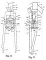
- FIG. 12 the rear fork portion 140 of a modified bicycle frame 12 is illustrated in accordance with a third example of the present invention.
- this third example differs from the first embodiment in that the seat stay 41 of frame 12 has been modified to support a side pull caliper brake device 114.
- the third example utilizes many of the same parts of the first embodiment, these parts will be given the same reference numerals.
- a pair of tubular frame members 115 are coupled to the frame members 43 of the seat stay 41.
- Each of the tubular frame members 115 have an axially aligned hole for receiving pivot or mounting pin 180.
- Pin 180 is preferably a bolt and nut arrangement.
- the frame members 115 are parallel to each other and together form a brake mounting structure.
- frame members 115 basically correspond to brake mounting flanges 91 of brake mounting structure 15.
- Brake device 114 is operatively coupled to a brake operating device via brake cable 62 which has an inner brake wire 63 and an outer casing 64. Basically, the rider will operate the brake operating device coupled to the handlebar which will in turn cause the brake arms 172a and 172b of brake device 114 to move inwardly to apply a braking force against the rim of the rear bicycle wheel 23. Upon release of the brake operating device, brake device 114 will release the rim to allow the bicycle wheel 23 to freely rotate.
- a modified rear fork portion 40 of a bicycle frame 12 is illustrated in accordance with a fourth example of the present invention.
- This fourth example differs from the first embodiment in that the seat stay 41 of frame 12 has been slightly modified to support a center pull caliper brake device 214 in a manner which is similar to the second example.
- the fourth example utilizes many of the same parts of the first embodiment and second example, these parts will be given the same reference numerals.
- Caliper brake device 214 is a center pull type brake, which is mounted to the seat stay 41 of the rear fork via a mounting structures 15'.
- caliper brake device 214 basically has a brake arm bridge 271 with a pair of brake aims 272a and 272b pivotally coupled to brake arm bridge 271 by pivot pins 280.
- the brake arm bridge 271 is fixedly coupled to the brake mounting structure 15' via a center mounting bolt 281.
- the brake arms 272a and 272b are normally biased relative to brake arm bridge 271 by a return spring 273 to a release position. In the release position, the brake pads of the brake shoes 275a and 275b are spaced from the rim of the rear wheel 23.
- a brake mounting structure like the one shown in figure 7 can be used with a pair of frame members as needed and/or desired.
- a more conventional front fork can be used to mount brake device 214 thereto in accordance with the present invention.
- Brake device 214 is supported by brake mounting structure 15' to rigid tubular frame member 225 of seat stay 41.
- seat stay 41 has two pairs of rigid tubular frame members 43 with their upper ends coupled seat tube 34, and their lower ends joined together by a pair of front wheel mounting ends or plates 44.
- Each of the rear wheel mounting ends or plates 44 has an open ended slot 45 for fixedly receiving the axle of the rear hub of wheel 23 in a conventional manner.
- seat stay 41 also has a frame member 225, which extends between opposite frame members 43.
- Brake device 214 is operatively coupled to a brake operating device via brake cable 62 which has an inner brake wire 63 and an outer casing 64. Basically, the rider will operate the brake operating device coupled to the handlebar which will in turn cause the brake arms 272a and 272b of brake device 214 to move inwardly to apply a braking force against the rim of the rear bicycle wheel 23. Upon release of the brake operating device, brake device 214 will release the rim to allow the bicycle wheel 23 to freely rotate.
- FIG. 18 the rear fork portion 140" of a modified bicycle frame 12 is illustrated in accordance with a fifth example of the present invention, which is similar to the second embodiment.
- This fifth example differs from the second embodiment in that the chain stay 142 of frame 12 has been modified to support the side pull caliper brake device 114.
- the fifth example utilizes many of the same parts of the first and second embodiment, these parts will be given the same reference numerals.
- a pair of tubular frame members 115' are coupled to the frame members 43 of the seat stay 41.
- Each of the tubular members 115' have an axially aligned hole for receiving pivot pin 380.
- the frame members 115' are parallel to each other, and together form a brake mounting structure.
- frame members 115' basically corresponds to brake mounting flanges 91 of brake mounting structure 15.
- Brake device 114 is operatively coupled to a brake operating device via brake cable 62 which has an inner brake wire 63 and an outer casing 64. Basically, the ride will operate the brake operating device coupled to the handlebar which will in turn cause the brake device 114 to move inwardly to apply a braking force against the rim of the rear bicycle wheel 23. Upon release of the brake operating device, brake device 114 will release the rim to allow the bicycle wheel 23 to freely rotate.
- a modified rear fork portion 140 of a bicycle frame 12 is illustrated in accordance with a sixth example of the present invention, which is similar to the second embodiment.
- This sixth example embodiment differs from the second embodiment in that the chain stay 142 of frame 12 has been modified to support a center pull caliper brake device 214 in a manner that is similar to the second example.
- only the main differences of the sixth example will be discussed and illustrated herein.
- the sixth example utilizes many of the same parts of the first and second embodiments and the second example, these parts will be given the same reference numerals.
- Caliper brake device 214 is a center pull type brake, which is mounted to the chain stay 142 via a mounting structure 15'.
- Caliper brake device 214 has a brake arm bridge 271 with a pair of brake arms 272a and 272b pivotally coupled to brake arm bridge 271 by pivot pins 280.
- the brake arm bridge 271 is fixedly coupled to the brake mounting structure 15' via a center mounting bolt 281.
- the brake arms 272a and 272b are normally biased relative to brake arm bridge 271 by a return spring 273 to a release position. In the release position, the brake pads of the brake shoes 275a and 275b are spaced from the rim of the rear wheel 23.
- Brake device 214 is supported by brake mounting structure 15' to rigid tubular frame member 225 of chain stay 142. More specifically, similar to the second embodiment, chain stay 142 has two pairs of rigid tubular frame members 146 with one of their ends coupled to the bottom bracket shell 35, and their other ends joined together by a pair of rear wheel mounting ends or plates 144. Each of the rear wheel mounting ends or plates 144 has an open ended slot 145 for fixedly receiving the axle of the rear hub of wheel 23 in a conventional manner. However, unlike the second embodiment, front fork 218 also has a frame member 225 which extends between opposite frame members 146.
- a brake mounting structure like the one shown in figure 7 can be used with a pair of frame members as needed and/or desired.
- a more conventional front fork can be used to mount brake device 214 thereto in accordance with the present invention.
- Brake device 214 is operatively coupled to a brake operating device via brake cable 62 which has an inner brake wire 63 and an outer casing 64. Basically, the rider will operate the brake operating device coupled to the handlebar which will in turn cause the brake device 214 to move inwardly to apply a braking force against the rim of the rear bicycle wheel 23. Upon release of the brake operating device, brake device 214 will release the rim to allow the bicycle wheel 23 to freely rotate.
- FIG. 22 and 23 a portion of bicycle frame 12 with a modified rear fork 40 is illustrated in accordance with a seventh example of the present invention.
- This seventh example is similar to the third example except that the side pull caliper brake device 114 is attached to frame members 115 via a single bicycle brake mounting 15.
- the seventh example utilizes many of the same parts of the first embodiment and third example, these parts will be given the same reference numeral.
- FIG. 24 a modified brake mounting structure 15' is illustrated in accordance with another explanatory example of the present invention.
- This mounting structure 15' has its intermediate section coupled directly to a tubular frame section 12' for supporting bicycle brake device 14 of the first embodiment in substantially the same manner as discussed in the preceding embodiments which utilizes a brake mounting structure 15.
- This tubular frame section 12' can be part of the front bicycle fork, the seat stay and/or chain stay of a modified bicycle frame.
- this tubular frame section 12' will not be discussed or illustrated in detail herein.
- a tubular frame section 313 is illustrated in accordance with another embodiment of the present invention.
- This tubular frame section 313 can be utilized to support a bicycle brake device in substantially the same manner as discussed in the preceding embodiments and examples which utilizes a brake mounting structure 15.
- This tubular frame section can be part of the front bicycle fork, the seat stay and/or chain stay of a modified bicycle frame.
- this tubular fork section will not be discussed or illustrated in detail herein.
- a tubular frame section 413 is illustrated in accordance with still another embodiment of the present invention.
- This tubular frame section 413 can be utilized to support a bicycle brake device in substantially the same manner as discussed in the preceding embodiments and examples which utilizes a brake mounting structure 15.
- This tubular frame section can be part of the front bicycle fork, the seat stay and/or chain stay of a modified bicycle frame.
- this tubular fork section will not be discussed or illustrated in detail herein.
- a bicycle brake device which is coupled to a bicycle frame section, which includes one or more bicycle brake mounting structures.
- the bicycle frame section can be either a portion of a front fork or rear fork of a bicycle.
- the brake device is preferably a caliper brake device such as a cantilever brake device, a side pull brake device, or a center pull brake device.
- the caliper brake device has a pair of brake arms which are pivotally coupled to either the front fork or rear fork for selectively engaging the rim of the bicycle wheel.
- the bicycle brake mounting structures are U-shaped brackets, which are fixedly coupled to the frame member or members.
- the bicycle brake mounting structures are formed by a pair of separate tubular frame members, which are fixedly coupled top the remainder of the bicycle frame section.
- the bicycle brake mounting structure or structures support both ends of pivot pins, while in the case of center pull brake devices, the bicycle brake mounting structure or structures support both ends of the center mounting pin.
Description
- This invention relates to a bicycle frame section according to the preamble of claim 1 as disclosed in document US-A-4,008,903.
- Bicycling is becoming an increasingly more popular form of recreation as well as a means of transportation. Moreover, bicycling has also become a very popular competitive sport for both amateurs and professionals. Whether the bicycle is used for recreation, transportation or competition, the bicycle industry is constantly improving the various components of the bicycle. One particular component of bicycles which has been extensively redesigned over the past years is the bicycle brake device. Bicycle brake devices are constantly being redesigned to provide additional braking power.
- There are several types of bicycle brake devices which are currently available on the market. Examples of some types of common bicycle brake devices include rim brakes and caliper brakes. With respect to caliper brakes, there are mainly three types of caliper brakes: a side pull type, a center pull type and cantilever type. In a side pull type of caliper brake device, a pair of brake arms are pivotally connected together about a center mounting bolt which attaches to the frame of the bicycle. Each of the brake arms has a lever portion which is coupled to the brake wire such that when the rider operates the brake lever of the brake operating device, the lever portions of the brake arms are pulled together, which in turn move the brake shoes attached to the other ends of the brake arms together against the rim of the bicycle wheel. Return springs are provided for biasing the brake arms away from the bicycle wheel rim when the rider releases the brake lever. Side pull types of caliper brake devices are commonly used in road bikes.
- A center pull type of caliper brake device operates similar to the side pull type, except that the brake arms are typically attached to a brake arm bridge such that each brake arm is pivotally coupled at a separate pivot point on the brake arm bridge. The brake arm bridge is attached directly to the frame of the bicycle. A straddle cable interconnects the two lever portions of the brake arms such that a main brake wire, which is coupled to the straddle wire, pulls the lever portions of the brake arms together.
- A cantilever type of caliper brake device is generally mounted on bicycles designed for off road use such as mountain bikes (MTB) and all terrain bikes (ATB). In particular, a cantilever type brake device is designed to provide a powerful braking force. A cantilever type of brake device is equipped with a pair of brake arms which are rotatably supported in a cantilever fashion on the front or rear fork of the bicycle frame, with the brake shoes attached to the upper portions of the brake arms. Typically, the lower ends of the brake arms are rotatably supported on the bicycle frame and the upper ends are linked to a brake cable or wire. The brake shoes are arranged opposite one another on either side of the bicycle wheel rim which is located between the arms. With this cantilever type of caliper brake device, the bicycle arms rotate in the closing direction when the brake cable is pulled by the brake lever, which in turn results in the brake shoes being pressed against the rim to apply a braking force.
- Cantilever types of caliper brake devices have several advantages over side pull types of caliper brake devices. For example, with such a cantilever brake device, there is no need to vary the shape of the device with the size of the bicycle, as may be the case with a side pull type of caliper brake device. Moreover, cantilever type of caliper brake devices apply a more equal braking force than a side pull type caliper brake.
- In view of the above, there exists a need for a bicycle frame section or a brake mounting structure which more securely supports a bicycle brake device. Moreover, there exists a need for an improved bicycle frame section or a brake mounting structure provides improved performance of caliper brakes such as increased braking force. This invention addresses these needs in the art as well as other needs in the art which will become apparent to those skilled in the art from this disclosure.
- In the US 4,008,903 a bicycle frame section is shown which is made of a plastic material. The frame section is a one piece unitary member which includes ribs and profiles which are directed outwardly of the frame section. In order to support s brake arm of a brake device bearings are provided in mouldings which are integrally formed and moulded to the bicycle frame member, i.e. they are part of the bicycle frame member. The mouldings support opposite sides of a mounting portion of a bicycle brake device therebetween.
- As the mouldings are integral parts of the bicycle frame there is no need for compensation of tolerances which might occur by welding two frame parts together or due to inaccuracies during the production to different frame models. Further the brake mounting members can not be adadpted to various kinds of configurations of frame members and can not be used for adjusting the brake to different wheels, i.e. adjusting the longitudinal position o the brake mounting members with respect to the frame members.
- According to the invention, a bicycle frame section as defined in claim 1 is provided.
- It is therefore an object of the present invention to provide an improved bicycle frame section and a brake mounting structure which support securely a bicycle brake device and which provides improved performance of caliper brakes such as increased breaking force.
- It is another object of the present invention to provide an improved bicycle frame section and a brake mounting structure which can be adapted to various kinds of configurations of frame members, can compensate tolerances which might occur by welding two frame parts together or due to inaccuracies during the production to different frame models and is more flexible in adjusting the brake device to different wheels of the bicycle.
- Still another object of the present invention is to provide a bicycle frame section which can be manufactured using conventional manufacturing methods.
- The foregoing objects can basically be attained by providing a bicycle frame section, comprising a first frame member, the first frame member being arranged on the left or the right side of the bicycle frame, a second frame member spaced from said first frame member, the second frame member being arranged on the same side of the bicycle frame as the first frame member, a first brake mounting member coupled to said first frame member and a second brake mounting member coupled to said second frame member, said first and second brake mounting members being configured to support opposite sides of a mounting portion of a bicycle brake device therebetween and said first and second brake mounting members are formed as separate parts with regard to said first and second frame members.
- The foregoing objects can also basically be attained by providing a bicycle frame section, comprising a first rigid frame member; a second rigid frame member spaced from the first rigid frame member; a first brake mounting member coupled to the first rigid frame member; and a second brake mounting member coupled to the second rigid frame member, the first and second brake mounting members being configured to support opposite sides of a mounting portion of a bicycle brake device therebetween.
- The foregoing objects can also basically be attained by providing a bicycle frame section, comprising bicycle frame means for supporting a part of a bicycle, the bicycle frame means having first and second frame members spaced apart from each other, first brake mounting means, coupled to the first frame member, for supporting a first end of a mounting member of a brake arm; and second brake mounting means, coupled to the second frame member, for supporting a second end of the mounting member of a brake arm.
- In addition, the foregoing objects can basically be attained by providing a bicycle frame section, comprising a first brake mounting member adapted to be coupled to a bicycle frame, a second brake mounting member adapted to be coupled to the bicycle frame; and a connecting member coupled between the first and second mounting members to form a brake device receiving recess therebetween.
- Other objects, advantages and salient features of the present invention will become apparent to those skilled in the art from the following detailed description, which, taken in conjunction with the annexed drawings, discloses preferred embodiments of the present invention.
- Referring now to the attached drawings which form a part of this original disclosure:
- Figure 1 is a side elevational view of an MTB style bicycle implementing a bicycle frame with front and rear cantilever brake devices coupled thereto via bicycle brake mounting structures in accordance with a first embodiment of the present invention;
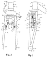
- Figure 2 is a partial front elevational view of the front fork with the front cantilever bicycle brake device coupled thereto via a pair of brake mounting structures in accordance with a first embodiment of the present invention;
- Figure 3 is a partial right side elevational view of the front fork illustrated in Figures 1 and 2 with certain parts removed for purposes of illustration;
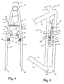
- Figure 4 is a partial top view of the seat stay section of the rear fork illustrated in Figure 1 with the rear cantilever bicycle brake device coupled thereto via a pair of brake mounting structures in accordance with a first embodiment of the present invention;
- Figure 5 is a partial side elevational view of the seat stay section of the rear fork illustrated in Figures 1 and 4 with the rear cantilever bicycle brake device coupled thereto;
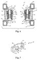
- Figure 6 is a cross-sectional view of the front bicycle brake device as seen along section line 6-6 of Figure 2 with the brake mounting structures fixedly coupled to the front fork of the bicycle frame;
- Figure 7 is a perspective view of one of the brake mounting structures in accordance with the first embodiment of the present invention;
- Figure 8 is a partial front elevational view of a modified front fork with a side pull brake device coupled thereto in accordance with a first explanatory example of the present invention;
- Figure 9 is a partial left side elevational view of the modified front fork and the side pull brake device illustrated in Figure 8;
- Figure 10 is a partial front elevational view of a modified front fork with a center pull brake device coupled thereto via a brake mounting structure in accordance with a second explanatory example of the present invention;
- Figure 11 is a partial right side elevational view of the front fork and center pull brake device illustrated in Figure 10;
- Figure 12 is a partial top view of a modified bicycle frame having a side pull brake device movably coupled directly to the seat stay section via a pair of brake mounting members or structures in accordance with a third explanatory example of the present invention;
- Figure 13 is a partial side elevational view of the modified bicycle frame illustrated in Figure 12 with the side pull brake device movably mounted to the seat stay section via the brake mounting members or structures;
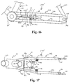
- Figure 14 is a partial top view of a modified bicycle frame with a center pull brake device movably coupled to the seat stay section via a bicycle brake mounting structure in accordance with a fourth explanatory example of the present invention;
- Figure 15 is a partial side elevational view of the modified bicycle frame illustrated in Figure 14 with the center pull brake device movably attached to the seat stay section via the brake mounting structures;
- Figure 16 is a partial side elevational view of a modified bicycle frame with a cantilever brake device movably coupled to the chain stay section via a pair of bicycle brake mounting structures in accordance with a second embodiment of the present invention;
- Figure 17 is a partial top view of the modified bicycle frame illustrated in Figure 16 with the cantilever brake device movably attached to the chain stay section via the brake mounting structures;
- Figure 18 is a side elevational view of a modified bicycle frame with a side pull brake device movably coupled to the chain stay section via a pair of frame mounting members or structures in accordance with a fifth explanatory example of the present invention;
- Figure 19 is a partial top view of the modified bicycle frame illustrated in Figure 18 with the side pull brake device movably attached to the chain stay section via a pair of frame mounting members or structures;
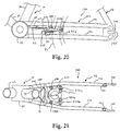
- Figure 20 is a partial side elevational view of a modified bicycle frame with a center pull brake device movably coupled to the chain stay section via a bicycle brake mounting structure in accordance with a sixth explanatory example of the present invention;
- Figure 21 is a partial top view of the modified bicycle frame illustrated in Figure 20 with the center pull brake device attached to the chain stay section via the brake mounting structure;
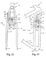
- Figure 22 is a partial front elevational view of a modified frame section with a side pull brake device coupled thereto via a brake mounting structure in accordance with a seventh explanatory example of the present invention;
- Figure 23 is a partial left side elevational view of the front fork and the side pull brake device illustrated in Figure 25;
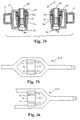
- Figure 24 is a cross-sectional view, similar to Figure 6, of a tubular frame section with a pair of U-shaped bicycle brake mounting structures coupled to the section of a bicycle frame in accordance with the present invention;
- Figure 25 is a side elevational view of a tubular frame section with a bicycle mounting structure coupled thereto for supporting a bicycle brake device in a manner in accordance with the present invention; and
- Figure 26 is a side elevational view of another tubular frame section with a bicycle mounting structure coupled thereto for supporting a bicycle brake in a manner in accordance with the present invention.
-
- Referring initially to Figure 1, a
bicycle 10 having abicycle frame 12 is illustrated in accordance with a first embodiment of the present invention.Bicycle frame 12 has a pair ofbicycle brake devices 14 fixedly coupled to frame 12 viabrake mounting structures 15 in accordance with a first embodiment of the present invention. While a MTB style bicycle is illustrated, it will be apparent to those skilled in the art from this disclosure that the present invention can be used with other styles of bicycles without departing from the scope of the present invention. - Basically,
bicycle frame 12 has a mainbicycle frame body 16, which constitutes the skeleton of the bicycle body.Bicycle frame body 16 is generally constructed of rigid tubular frame sections or members which are rigidly coupled together by welding or any other conventional method. The tubular frame members can be constructed of any suitable rigid material such as aluminum, titanium, etc. -
Bicycle frame 12 also has afront fork 18 constructed mainly of rigid tubular frame members which are rigidly coupled together by welding or any other conventional method.Front fork 18 is rotatably supported byframe body 16 to rotate about an inclined vertical axle in the front portion offrame body 16. Thebicycle 10 further comprises ahandlebar 20 that is fixedly coupled to thefront fork 18, adrive train 21 that is attached to the lower portion of theframe body 16 for converting a pedaling force to drive force, afront wheel 22 that is rotatably supported at the lower end of thefront fork 18, arear wheel 23 that is rotatably supported in the back portion of theframe body 16, and front and back brakingdevices 14. - As seen in Figures 2 and 3, the
front fork 18 is rotatably coupled at its upper end to framebody 16 and has a bifurcated lower portion for receiving afront wheel 22 therebetween (Figure 1). Thefront fork 18 has two pairs of rigidtubular frame members 24 with their upper ends coupled together by an intermediate or connectingmember 26 and their lower ends joined together by a pair of front wheel mounting ends orplates 27. Each of the front wheel mounting ends orplates 27 has an open endedslot 28 for fixedly receiving the axle of the front hub ofwheel 22 in a conventional manner. - As seen in figures 2, 3 and 6, the front
bicycle brake device 14 is fixedly coupled tofront fork 18 via a pair ofbrake mounting structures 15. Each of thebrake mounting structures 15 is rigidly and fixedly coupled to a pair ofadjacent frame members 24. For example,brake mounting structures 15 are welded betweenframe members 24. Brake mountingstructures 15 are shown in Figures 6 and 7 and discussed in detail below. - Referring again to Figure 1, the
handlebar 20 has a handlebar stem adjustably coupled to the top portion of thefront fork 18 for adjusting the height of the handlebar, and a pair of handle portions extending to the right and left from the top end of the handlebar stem. Grips (only one shown) are fitted on the two ends of the handle portions of thehandlebar 20. Brake levers 29 (only one shown) and shifting levers 30 (only one shown) are located adjacent to these grips in a conventional manner. The general construction and operation of brake levers 29 and shiftinglevers 30 are generally old and well known, and thus, they will not be discussed or illustrated in detail herein. - Still referring to Figure 1, the
frame body 16 is a diamond shaped frame with a front triangle and a back triangle located behind the front triangle. Of course, the present invention can be used with other types of bicycle frames. The front triangle comprises a horizontally disposedtop tube 31, an angled downtube 32 that is located beneath thetop tube 31 and that rises toward the front, ahead tube 33 for joining the front ends of thetop tube 31 and thedown tube 32, and aseat tube 34 that rises at an angle and joins the back ends of thetop tube 31 and thedown tube 32. Abottom bracket shell 35 is formed at the joint between theseat tube 34 and thedown tube 32. Aseat post 36 equipped with asaddle 37 is slideably coupled to theseat tube 34 for vertically adjusting the position of theseat post 36 andsaddle 37. - The back triangle comprises a rear or
back fork 40 having aseat stay 41 rigidly coupled toseat tube 34 and achain stay 42 rigidly coupled tobottom bracket shell 35. In particular, theseat stay 41 has four rigidtubular frame members 43 with the front ends of eachtubular frame members 43 rigidly coupled toseat tube 34. Thetubular frame members 43 extend downwardly fromseat tube 34 in a bifurcated manner for receivingrear wheel 23 therebetween. In other words, a pair oftubular frame members 43 are located on each side ofrear wheel 23. The rear ends of adjacenttubular frame members 43 are each interconnected together by a rear fork mounting end orplate 44. Each of the rear fork mounting ends orplates 44 has an open endedslot 45 for fixedly receiving the axle of the rear hub in a conventional manner. - As seen in Figures 4 and 5, the rear
bicycle brake device 14 of the first embodiment is also fixedly coupled to theseat stay 41 via a pair ofbrake mounting structures 15. In other words, the front and rearbicycle brake devices 14 are fixedly coupled toframe 12 in substantially the same manner, except for different frame members. Each of thebrake mounting structures 15 of the rearbicycle brake device 14 is rigidly and fixedly coupled to a pair ofadjacent frame members 43. For example,brake mounting structures 15 of the rearbicycle brake device 14 are welded to a pair ofadjacent frame members 43 as seen in Figure 5. - Referring to Figures 1 and 5, chain stay 42 has a pair of rigid
tubular frame members 46 with one of theframe members 46 located on each side of wheel rear 23.Chain stay 42 has the front ends oftubular frame members 46 rigidly coupled tobottom bracket shell 35 as seen in Figure 1. Thetubular frame members 46 extend backward frombottom bracket shell 35 where they are joined at their back ends by the rear fork mounting ends orplates 44. - As seen in Figure 1, the
drive train 21 basically comprises a front chainwheel and crankassembly 54 coupled to thebottom bracket shell 35, a set of rear chainwheels orsprockets 55 non-rotatably attached to the free hub ofrear wheel 23, achain 56 that passes over the front chainwheel and crankassembly 54 andrear chainwheels 55, and passes through front andrear derailleurs 57 and 58 for shifting gears in a conventional manner via shiftinglevers 30. - As shown in Figure 1, chainwheel and crank
assembly 54 comprises a bottom bracket (not shown), right and left crankarms 59, withpedals 60 attached to the tip of each crankarm 59. The bottom bracket connects right and left crankarms 59 together. A spindle is rotatably supported by the bottom bracket which in turn is mounted inbottom bracket shell 35 offrame body 16 in a conventional manner. - As seen in Figures 2 and 3, front
bicycle brake device 14 is coupled tofront fork 18 for engaging and applying a braking force against the rim offront bicycle wheel 22. Similarly, as seen in Figures 4 and 5, the rearbicycle brake device 14 is coupled torear fork 40 for engaging and applying a braking force against the rim ofrear bicycle wheel 23. In the first embodiment,bicycle brake devices 14 are illustrated as cantilever brake devices. Of course, it will be apparent to those skilled in the art from this disclosure thatbicycle frame 12 can be modified to accommodate other styles of brakes.Brake devices 14 have an increased braking force over prior art brake devices in that thebrake devices 14 are pivotally supported by mountingstructures 15 as discussed below. -
Bicycle brake devices 14 are operated in a substantially conventional manner by the rider via conventional brake operating devices or levers 29 which are mounted onhandle bar 20 ofbicycle 10 in a conventional manner. Bicycles and their various components are well-known in the prior art, and thus,bicycle 10 and its various components will not be discussed or illustrated in detail herein. - As best seen in Figures 1, 2 and 4,
brake devices 14 are operatively coupled to brake operatingdevices 29 viaconventional brake cables 62, each having aninner brake wire 63 and anouter casing 64. Basically, the rider operates one or both of thebrake operating devices 29 to cause one or both of thebrake devices 14 to move inwardly for applying a braking force against the rim of one or both of thebicycle wheels 22 and/or 23. Upon release of thebrake operating devices 29,brake devices 14 will release the rim to allowbicycle wheels - As best seen in Figures 2 and 4, each of the
brake devices 14 basically includes a pair of brake mechanisms 70a and 70b which are substantially mirror images of each other, except for their connections to brakecable 62. Referring to Figures 2-6, right brake mechanism 70a basically includes a mountingassembly 71 a, abrake arm 72a, a return spring 73a, and abrake shoe 75a, while left brake mechanism 70b basically includes a mounting assembly 71b, a brake arm 72b, a return spring 73b and abrake shoe 75b. Mountingassemblies 71a and 71b are fixedly coupled to brake mountingstructures 15 for fixedly couplingbrake device 14 to the tubular frame members offrame 12. -
Brake arms 72a and 72b are preferably constructed of a suitable rigid material. For example, the brake arms can be cast or machined from any suitable material such as aluminum, titanium, dense plastic, ceramic, acrylic, etc. Preferably, brakearms 72a and 72b are constructed of a lightweight material to minimize the weight ofbrake devices 14.Brake arms 72a and 72b are substantially identical to each other, except that their upper ends are slightly modified for accommodating conventional cable connections or wire mounting portions as seen in Figures 2 and 4. -
Brake arms 72a and 72b are pivotally coupled to mountingassemblies 71 a and 71b, respectively, for movement between a release position and a braking position. Return springs 73a and 73b are coupled between mountingassemblies 71a and 71b and brake aims 72a and 72b, respectively, for pivotally biasing brake aims 72a and 72b to their release positions.Brake shoes shoe attachment portions 74a and 74b ofbrake anus 72a and 72b, respectively. - Each of the mounting
assemblies 71 a and 71b are basically identical and include a mounting orpivot pin 80 and abushing arrangement 81. The mounting or pivot pins 80 are each preferably constructed of two pieces, e.g., abolt 82 and an internally threadedsleeve 83. Thebushing arrangements 81 surround pivot pins 80 and are fixedly secured to mountingstructures 15 via engagement pins 84 as seen in Figure 6. Since pivot pins 80 andbushing arrangements 81 are well-known in the art, they will not be discussed in detail herein. -
Brake arms 72a and 72b have their upper portions 85a and 85b coupled tobrake cable 62 for movingbrake arms 72a and 72b from a release position to a braking position. Specifically, upper portion 84a ofbrake arm 72a is coupled toinner brake wire 63 ofbrake cable 62 vialock bolt 87 which is received into a threaded hole.Lock bolt 87 clampsinner brake wire 63 against upper portion 85a ofbrake arm 72a. Theouter casing 64 ofbrake cable 62 is coupled to upper portion 85b of brake arm 72b by connectingarm 86. In particular, as best seen in Figure 4, connectingaim 86 is pivotally coupled to upper portion 85b of brake arm 72b andouter casing 64 ofbrake cable 62. Application ofbrake operating device 29 causes upper portions 85a and 85b to move inwardly towards each other and the friction pads ofbrake shoes 75a and/or 75b to engage the rim of thewheels 22 and/or 23. - The upper portions 85a and 85b of
brake arms 72a and 72b haveshoe attachment portions 74a and 74b integrally formed therewith. Of course, it will be apparent to those skilled in the art from this disclosure thatshoe attachment portions 74a and 74b can be pivotally coupled to brakearms 72a and 72b for attachingbrake shoes arms 72a and 72b each have a hole for receiving one of the pivot pins 80 therethrough, The lower portions ofbrake arms 72a and 72b are pivotally coupled to mountingassemblies 71a and 71b such thatbrake arms 72a and 72b can rotate about the pivot axes formed by pivot pins 80. - Return spring or biasing member 73a is fixedly coupled at one end to mounting assembly 71 via a fastener or screw in a conventional manner. Return spring 73a is designed to normally bias
brake arm 72a in a clockwise direction as seen in Figures 2 and 4. Accordingly,brake arm 72a is biased by return spring 73a such thatbrake shoe 75a normally moves away from the rim ofbicycle wheel - Return spring or biasing member 73b is similarly designed to normally bias brake arm 72b to a release position. Specifically, brake arm 72b is biased by return spring 73b in a counter-clockwise direction as seen in Figures 2 and 4. Accordingly, brake arm 72b is biased by return spring 73b such that
brake shoe 75b normally moves away from the rim ofbicycle wheel -
Brake shoe 75a is attached toshoe attachment portion 74a such thatbrake shoe 75a can be adjusted vertically to ensure proper engagement betweenbrake shoe 75a and the rim ofbicycle wheel brake shoe 75b is attached to shoe attachment portion 74b such thatbrake shoe 75b can be adjusted vertically to ensure proper engagement betweenbrake shoe 75b and the rim ofbicycle wheel - As seen in Figures 6 and 7, the
brake mounting structures 15 are preferably substantially U-shaped members which are fixedly and rigidly coupled to a pair of tubular frame members ofbicycle frame 12. Thebrake mounting structures 15 are constructed of a hard rigid material, such as steel, aluminum, titanium or a non metallic composite material. Basically, each bicyclebrake mounting structure 15 has an intermediate connectingmember 90 and a pair ofbrake mounting flanges 91 extending substantially perpendicular from opposite ends of an intermediate connectingmember 90. Anattachment flange 92 extends outwardly from each of the mountingflanges 91 for attaching mountingstructure 15 to framemembers 24 offront fork 18 as seen in Figure 6. A mountingrecess 94 is formed betweenflanges brake mounting structure 15 is welded or otherwise rigidly and fixedly secured to the tubular frame members such that the tubular frame members are located within therecesses 94. Each of thebrake mounting flanges 91 has apivot mounting hole 95 for receiving one end of thepivot pin 80 for the brake arm. Thepin mounting holes 95 are preferably axially aligned with one another. Also, one of the mountingflanges 91 of each of the mountingstructures 15 also has asmaller hole 96 for receiving one of the engagement pins 84 as seen in Figure 6 of the mountingassemblies 71a or 71b. - In operation, when the rider operates one or both of the brake levers of the
brake operating devices 29, theinner wire 63 of thebrake cable 62 is pulled within theouter casing 64 of thebrake cable 62 so that the upper portions 85a and 85b ofbrake arms 72a and 72b are pulled inwardly. Thereafter, the friction pads of thebrake shoes bicycle wheel 22 and/or 23, thus causing a braking action to be performed. In other words,brake arm 72a rotates in a counter clockwise direction aboutpivot pin 80 against the force of return spring 73a and brake arm 72b rotates in a clockwise direction aboutpivot pin 80 against the force of return spring 73b. Once the rider releases the brake lever of thebrake operating devices 29, theinner brake wire 63 of thebrake cable 62 is relaxed so that the return springs 73a and 73b cause thebrake arms 72a and 72b to pivot in their opening directions. As a result, the inner faces of the friction pads ofbrake shoes bicycle wheel 22 and/or 23 so that the braking action is released. - Referring now to Figures 16 and 17, the rear fork portion 140' of a modified
bicycle frame 12 is illustrated in accordance with a second embodiment of the present invention. This second embodiment differs from the first embodiment in that the chain stay 142 offrame 12 has been modified to supportcantilever brake device 14. In view of these similarities between the two embodiments, only the main differences between the first and second embodiment will be discussed and illustrated herein. Moreover, since the second embodiment utilizes many of the same parts of the first embodiment, these parts will be given the same reference numerals. - In this embodiment, the chain stay 142 is constructed of four
tubular frame members 146 with the front end of eachframe member 146 rigidly coupled to thebottom bracket shell 35 by welds. The rear ends of twoadjacent frame members 146 are coupled together by wheel mounting ends orplates 144. Thewheel mounting plates 144 have open endedslots 145 for receiving the axle of the rear hub. Adjacent pairs of theframe members 146 have mountingstructures 15 fixedly coupled thereto forcoupling brake device 14 thereto in substantially the same manner as in the first embodiment. -
Brake device 14 is operatively coupled to a brake operating device viabrake cable 62 which has aninner brake wire 63 and anouter casing 64. Basically, the rider will operate the brake operating device coupled to the handlebar which will in turn cause thebrake device 14 to move inwardly to apply a braking force against the rim of therear bicycle wheel 23. Upon release of the brake operating device,brake device 14 will release the rim to allow thebicycle wheel 23 to freely rotate. - In the following there are several explanatory examples mentioned each disclosing an additional variation of the technical design of the present invention in order to enhance the understanding of the invention.
- Referring now to Figures 8 and 9, a portion of
bicycle frame 12 with a modifiedfront fork 118 is illustrated in accordance with a first example of the present invention. This first example differs from the first embodiment in that instead of utilizing acantilever brake device 14, a side pull type ofcaliper brake device 114 is used. Also, thefront fork 118 does not havebrake mounting structures 15. Rather, thefront fork 118 has been modified such thatattachment component 25 directly supportsbrake device 114. In view of these similarities between the first embodiment and first example, only the main differences between the first embodiment and first example will be discussed and illustrated herein. Moreover, since the first example utilizes many of the same parts of the first embodiment, these parts will be given the same reference numerals. -
Caliper brake device 114 is a side pull type of caliper brake, and basically comprises a pair ofbrake arms pivot pin 180. Thebrake arms brake shoes 175a and 175b are spaced from the rim of thefront wheel 22. - As in the first embodiment, each end of the
pivot pin 180 is supported by a rigid frame member or section offront fork 118. However, in this example, no mounting bracket is used. More specifically,front fork 118 has two pairs of rigidtubular frame members 24 with their upper ends coupled together by aU-shaped attachment component 25, and their lower ends joined together by a pair of front wheel mounting ends orplates 27. Each of the front wheel mounting ends orplates 27 has an open endedslot 28 for fixedly receiving the axle of the front hub ofwheel 22 in a conventional manner.Brake device 114 is fixedly coupled to theU-shaped attachment component 25 by thepivot pin 180. Preferably, thepivot pin 180 is comprised of a nut and bolt arrangement. As seen in Figure 9, both ends ofpivot pin 180 is supported by theU-shaped attachment component 25. Of course, other types of pivot pins could be utilized as needed and/or desired. -
Brake device 114 is operatively coupled to a brake operating device viabrake cable 62 which has aninner brake wire 63 and anouter casing 64. Basically, the rider will operate the brake operating device coupled to the handlebar which will in turn cause thebrake device 114 to move inwardly to apply a braking force against the rim of thefront bicycle wheel 22. Upon release of the brake operating device,brake device 114 will release the rim to allow thebicycle wheel 22 to freely rotate. - Referring now to Figures 10 and 11, a portion of
bicycle frame 12 with a modified front fork 218 is illustrated in accordance with a second example of the present invention. This second example differs from the first embodiment in that instead of utilizing acantilever brake device 14, a center pull type ofcaliper brake device 214 is used by adding atubular frame member 225 and a single brake mounting structure 15'. In view of these similarities between the first embodiment and the second example, only the main differences between the first embodiment and the second example will be discussed and illustrated herein. Moreover, since the second example utilizes many of the same parts of the first embodiment, these parts will be given the same reference numerals. - Basically,
caliper brake device 214 has abrake arm bridge 271 with a pair ofbrake arms brake arm bridge 271 by pivot pins 280. Thebrake arm bridge 271 is fixedly coupled to the brake mounting structure 15' via acenter mounting bolt 281. The brake aims 272a and 272b are normally biased relative to brakearm bridge 271 by areturn spring 273 to a release position. In the release position, the brake pads of thebrake shoes 275a and 275b are spaced from the rim of thefront wheel 22. -
Brake device 214 is supported by brake mounting structure 15', which in turn is rigidly mounted to rigidtubular frame members 225 of front fork 218. More specifically, similar to the first embodiment, front fork 218 has two pairs of rigidtubular frame members 24 with their upper ends coupled together by aU-shaped attachment component 25, and their lower ends joined together by a pair of front wheel mounting ends orplates 27. Each of the front wheel mounting ends orplates 27 has an open endedslot 28 for fixedly receiving the axle of the front hub ofwheel 22 in a conventional manner. However, unlike the first embodiment, front fork 218 also has aframe member 225, which extends betweenopposite frame members 24. Brake mounting structure 15' is fixedly coupled toframe member 225 by welds or any other suitable method. - It will be apparent to those skilled in the art that a brake mounting structure like the one shown in Figure 7 can be used with a pair of frame members as needed and/or desired. Moreover, a more conventional front fork can be used to mount
brake device 214 thereto in accordance with the present invention. -
Caliper brake device 214 is a center pull type brake, which is mounted to front fork 218 via a mounting structure 15'. Mounting structure 15' is a substantially U-shaped member, which is similar to mountingstructure 15 of the first embodiment. Brake mounting structure 15' is preferably fixedly and rigidly coupled toframe member 225 ofbicycle frame 12. Basically, bicycle brake mounting structure 15' has an intermediate connecting member and a pair of brake mounting flanges extending substantially perpendicular from opposite ends of an intermediate connecting member. Each of the brake mounting flanges has a mounting hole for receiving one end of the mountingpin 281 of thebicycle brake device 214. The pin mounting holes are preferably axially aligned with one another. A mounting recess is formed between flanges for receiving thebrake bridge arm 271 ofbicycle brake device 214 therebetween. Preferably, brake mounting structure 15' is welded or otherwise rigidly and fixedly secured to thetubular frame member 225. -
Brake device 214 is operatively coupled to a brake operating device viabrake cable 62 which has aninner brake wire 63 and anouter casing 64. Basically, the rider will operate the brake operating device coupled to the handlebar which will in turn cause thebrake arms brake device 214 to move inwardly to apply a braking force against the rim of thefront bicycle wheel 22. Upon release of the brake operating device,brake device 214 will release the rim to allow thebicycle wheel 22 to freely rotate. - Referring now to Figures 12 and 13, the
rear fork portion 140 of a modifiedbicycle frame 12 is illustrated in accordance with a third example of the present invention. Specifically, this third example differs from the first embodiment in that the seat stay 41 offrame 12 has been modified to support a side pullcaliper brake device 114. In view of these similarities between the first embodiment and the third example, only the main differences between the first embodiment and the third example will be discussed and illustrated herein. Moreover, since the third example utilizes many of the same parts of the first embodiment, these parts will be given the same reference numerals. - Specifically, a pair of
tubular frame members 115 are coupled to theframe members 43 of theseat stay 41. Each of thetubular frame members 115 have an axially aligned hole for receiving pivot or mountingpin 180.Pin 180 is preferably a bolt and nut arrangement. Preferably, theframe members 115 are parallel to each other and together form a brake mounting structure. In other words,frame members 115 basically correspond to brake mountingflanges 91 ofbrake mounting structure 15. -
Brake device 114 is operatively coupled to a brake operating device viabrake cable 62 which has aninner brake wire 63 and anouter casing 64. Basically, the rider will operate the brake operating device coupled to the handlebar which will in turn cause thebrake arms brake device 114 to move inwardly to apply a braking force against the rim of therear bicycle wheel 23. Upon release of the brake operating device,brake device 114 will release the rim to allow thebicycle wheel 23 to freely rotate. - Referring now to Figures 14 and 15, a modified
rear fork portion 40 of abicycle frame 12 is illustrated in accordance with a fourth example of the present invention. This fourth example differs from the first embodiment in that the seat stay 41 offrame 12 has been slightly modified to support a center pullcaliper brake device 214 in a manner which is similar to the second example. In view of these similarities between the fourth example and the first embodiment and second example, only the main differences of the fourth example will be discussed and illustrated herein. Moreover, since the fourth example utilizes many of the same parts of the first embodiment and second example, these parts will be given the same reference numerals. -
Caliper brake device 214 is a center pull type brake, which is mounted to the seat stay 41 of the rear fork via a mounting structures 15'. As mentioned above,caliper brake device 214 basically has abrake arm bridge 271 with a pair of brake aims 272a and 272b pivotally coupled tobrake arm bridge 271 by pivot pins 280. Thebrake arm bridge 271 is fixedly coupled to the brake mounting structure 15' via acenter mounting bolt 281. Thebrake arms arm bridge 271 by areturn spring 273 to a release position. In the release position, the brake pads of thebrake shoes 275a and 275b are spaced from the rim of therear wheel 23. - It will be apparent to those skilled in the art that a brake mounting structure like the one shown in figure 7 can be used with a pair of frame members as needed and/or desired. Moreover, a more conventional front fork can be used to mount
brake device 214 thereto in accordance with the present invention. -
Brake device 214 is supported by brake mounting structure 15' to rigidtubular frame member 225 ofseat stay 41. More specifically, similar to the first embodiment, seat stay 41 has two pairs of rigidtubular frame members 43 with their upper ends coupledseat tube 34, and their lower ends joined together by a pair of front wheel mounting ends orplates 44. Each of the rear wheel mounting ends orplates 44 has an open endedslot 45 for fixedly receiving the axle of the rear hub ofwheel 23 in a conventional manner. However, unlike the first embodiment, seat stay 41 also has aframe member 225, which extends betweenopposite frame members 43. -
Brake device 214 is operatively coupled to a brake operating device viabrake cable 62 which has aninner brake wire 63 and anouter casing 64. Basically, the rider will operate the brake operating device coupled to the handlebar which will in turn cause thebrake arms brake device 214 to move inwardly to apply a braking force against the rim of therear bicycle wheel 23. Upon release of the brake operating device,brake device 214 will release the rim to allow thebicycle wheel 23 to freely rotate. - Referring now to Figures 18 and 19, the
rear fork portion 140" of a modifiedbicycle frame 12 is illustrated in accordance with a fifth example of the present invention, which is similar to the second embodiment. This fifth example differs from the second embodiment in that the chain stay 142 offrame 12 has been modified to support the side pullcaliper brake device 114. In view of these similarities between the second embodiment and the fifth example, only the main differences between the second embodiment and the fifth example will be discussed and illustrated herein. Moreover, since the fifth example utilizes many of the same parts of the first and second embodiment, these parts will be given the same reference numerals. - Specifically, a pair of tubular frame members 115' are coupled to the
frame members 43 of theseat stay 41. Each of the tubular members 115' have an axially aligned hole for receiving pivot pin 380. Preferably, the frame members 115' are parallel to each other, and together form a brake mounting structure. In other words, frame members 115' basically corresponds to brake mountingflanges 91 ofbrake mounting structure 15. -
Brake device 114 is operatively coupled to a brake operating device viabrake cable 62 which has aninner brake wire 63 and anouter casing 64. Basically, the ride will operate the brake operating device coupled to the handlebar which will in turn cause thebrake device 114 to move inwardly to apply a braking force against the rim of therear bicycle wheel 23. Upon release of the brake operating device,brake device 114 will release the rim to allow thebicycle wheel 23 to freely rotate. - Referring now to Figures 20 and 21, a modified
rear fork portion 140 of abicycle frame 12 is illustrated in accordance with a sixth example of the present invention, which is similar to the second embodiment. This sixth example embodiment differs from the second embodiment in that the chain stay 142 offrame 12 has been modified to support a center pullcaliper brake device 214 in a manner that is similar to the second example. In view of these similarities between the sixth example and the prior embodiments and examples, only the main differences of the sixth example will be discussed and illustrated herein. Moreover, since the sixth example utilizes many of the same parts of the first and second embodiments and the second example, these parts will be given the same reference numerals. -
Caliper brake device 214 is a center pull type brake, which is mounted to the chain stay 142 via a mounting structure 15'.Caliper brake device 214 has abrake arm bridge 271 with a pair ofbrake arms brake arm bridge 271 by pivot pins 280. Thebrake arm bridge 271 is fixedly coupled to the brake mounting structure 15' via acenter mounting bolt 281. Thebrake arms arm bridge 271 by areturn spring 273 to a release position. In the release position, the brake pads of thebrake shoes 275a and 275b are spaced from the rim of therear wheel 23. -
Brake device 214 is supported by brake mounting structure 15' to rigidtubular frame member 225 ofchain stay 142. More specifically, similar to the second embodiment, chain stay 142 has two pairs of rigidtubular frame members 146 with one of their ends coupled to thebottom bracket shell 35, and their other ends joined together by a pair of rear wheel mounting ends orplates 144. Each of the rear wheel mounting ends orplates 144 has an open endedslot 145 for fixedly receiving the axle of the rear hub ofwheel 23 in a conventional manner. However, unlike the second embodiment, front fork 218 also has aframe member 225 which extends betweenopposite frame members 146. - It will be apparent to those skilled in the art that a brake mounting structure like the one shown in figure 7 can be used with a pair of frame members as needed and/or desired. Moreover, a more conventional front fork can be used to mount
brake device 214 thereto in accordance with the present invention. -
Brake device 214 is operatively coupled to a brake operating device viabrake cable 62 which has aninner brake wire 63 and anouter casing 64. Basically, the rider will operate the brake operating device coupled to the handlebar which will in turn cause thebrake device 214 to move inwardly to apply a braking force against the rim of therear bicycle wheel 23. Upon release of the brake operating device,brake device 214 will release the rim to allow thebicycle wheel 23 to freely rotate. - Referring now to Figures 22 and 23, a portion of
bicycle frame 12 with a modifiedrear fork 40 is illustrated in accordance with a seventh example of the present invention. This seventh example is similar to the third example except that the side pullcaliper brake device 114 is attached to framemembers 115 via a single bicycle brake mounting 15. In view of these similarities between these examples, only the main differences between these examples will be discussed and illustrated herein. Moreover, since the seventh example utilizes many of the same parts of the first embodiment and third example, these parts will be given the same reference numeral. - Referring now to Figure 24, a modified brake mounting structure 15' is illustrated in accordance with another explanatory example of the present invention. This mounting structure 15' has its intermediate section coupled directly to a tubular frame section 12' for supporting
bicycle brake device 14 of the first embodiment in substantially the same manner as discussed in the preceding embodiments which utilizes abrake mounting structure 15. This tubular frame section 12' can be part of the front bicycle fork, the seat stay and/or chain stay of a modified bicycle frame. In view of the similarities between this embodiment and the prior embodiments and examples, this tubular frame section 12' will not be discussed or illustrated in detail herein. - Referring now to Figure 25, a
tubular frame section 313 is illustrated in accordance with another embodiment of the present invention. Thistubular frame section 313 can be utilized to support a bicycle brake device in substantially the same manner as discussed in the preceding embodiments and examples which utilizes abrake mounting structure 15. This tubular frame section can be part of the front bicycle fork, the seat stay and/or chain stay of a modified bicycle frame. In view of the similarities between this embodiment and the prior embodiments and examples, this tubular fork section will not be discussed or illustrated in detail herein. - Referring now to Figure 26, a
tubular frame section 413 is illustrated in accordance with still another embodiment of the present invention. Thistubular frame section 413 can be utilized to support a bicycle brake device in substantially the same manner as discussed in the preceding embodiments and examples which utilizes abrake mounting structure 15. This tubular frame section can be part of the front bicycle fork, the seat stay and/or chain stay of a modified bicycle frame. In view of the similarities between this embodiment and the prior embodiments and examples, this tubular fork section will not be discussed or illustrated in detail herein. - While several embodiments and explanatory examples of the present invention have been described and illustrated herein, it will be apparent to those skilled in the art once given this disclosure that various modifications, changes, improvements and variations may be made without departing from the spirit or scope of this invention as defined in the following claims.
- Summarized, a bicycle brake device is provided which is coupled to a bicycle frame section, which includes one or more bicycle brake mounting structures. The bicycle frame section can be either a portion of a front fork or rear fork of a bicycle. The brake device is preferably a caliper brake device such as a cantilever brake device, a side pull brake device, or a center pull brake device. The caliper brake device has a pair of brake arms which are pivotally coupled to either the front fork or rear fork for selectively engaging the rim of the bicycle wheel. In certain embodiments, the bicycle brake mounting structures are U-shaped brackets, which are fixedly coupled to the frame member or members. In other embodiments, the bicycle brake mounting structures are formed by a pair of separate tubular frame members, which are fixedly coupled top the remainder of the bicycle frame section. In the case of cantilever brake devices and side pull brake devices, the bicycle brake mounting structure or structures support both ends of pivot pins, while in the case of center pull brake devices, the bicycle brake mounting structure or structures support both ends of the center mounting pin.
Claims (21)
- A bicycle frame section, comprising:characterized in that said first and second brake mounting members are formed as separate parts with regard to said first and second frame members.a first frame member (24; 43; 146), the first frame member being arranged on the left or the right side of the bicycle frame;a second frame member (24; 43; 146) spaced from said first frame member (24; 43; 146), the second frame member being arranged on the same side of the bicycle frame as the first frame member;a first brake mounting member coupled to said first frame member (24; 43; 146); anda second brake mounting member coupled to said second frame member (24; 43; 146);said first and second brake mounting members being configured to support opposite sides of a mounting portion of a bicycle brake device (14; 114; 214) therebetween,
- A bicycle frame section according to claim 1, characterized in that
said first and second brake mounting members are connected together by an intermediate member (90) to form a substantially U-shaped member. - A bicycle frame section according to one of the preceding claims, characterized in that said first and second brake mounting members have first and second axially aligned holes (95), respectively.
- A bicycle frame section according to one of the preceding claims, characterized in that one of said first and second brake mounting members has a third hole (96).
- A bicycle frame section according to one of the preceding claims, characterized in that each of said first and second frame members (24; 43; 146) has a first end and a second end with said first ends of said first and second frame members (24; 43; 146) being coupled together and said second ends of said first and second frame members (24; 43; 146) being coupled together.
- A bicycle frame section according to one of the preceding claims, further comprising a third frame member (24; 43; 146);
a fourth frame member (24; 43; 146) coupled to said third frame member (24; 43; 146);
a third brake mounting member coupled to said third frame member (24; 43; 146); and
a fourth brake mounting member coupled to said fourth rigid frame member (24; 43; 146);
with said third and fourth brake mounting members being configured to pivotally support opposite sides of a brake arm (72a, 72b; 172a, 172b; 272a, 272b). - A bicycle frame section according to claim 6, characterized in that
said first, second, third and fourth frame members (24; 43; 146) are tubular members. - A bicycle frame section according to claim 6 or 7, characterized in that said first and second brake mounting members are connected together by a first intermediate member (90) to form a first substantially U-shaped member (15), and said third and fourth brake mounting members are connected together by a second intermediate member (90) to form a second substantially U-shaped member (15).
- A bicycle frame section according to any of the preceding claims characterized in that said bicycle brake device comprises a brake arm (72a, 72b; 172a, 172b; 272a, 272b) the brake arm including a first mounting member (71a, 71b, 171a, 171b; 271a, 271b), a first end of said first mounting member of said first brake arm being supported by said first frame member, and a second end being supported by said second frame member.
- A bicycle frame section according to one of the preceding claims, characterized in that said first and second frame members (24; 43; 146) are rigid tubular frame members.
- A bicycle frame section according to one of the preceding claims, characterized in that said first and second frame members (24) are rigidly coupled together to form at least part of a front bicycle fork (18; 118; 218).
- A bicycle frame section according to one of claims 1 - 10, characterized in that said first and second frame members (146) are rigidly coupled together to form at least part of a bicycle chain stay (42; 142).
- A bicycle frame section according to one of claims 1 - 10, wherein
said first and second frame members (43) are rigidly coupled together to form at least part of a seat stay (41). - A bicycle frame section according to one of the preceding claims, characterized in that said first and second frame members (24; 43; 145) are coupled together at one end by a bicycle wheel mounting portion (27; 44; 144) having a slot (28; 45; 145) adapted to receive an axle of a bicycle wheel (22; 23).
- A bicycle frame section according to one of claims 10 - 14, characterized in that
said first and second brake mounting means are substantially U-shaped members (15). - A bicycle frame section according to one of claims 10 - 15, characterized in that
said bicycle frame means further includes third and fourth frame members (24; 43: 146) coupled together; and
third brake mounting means, coupled to said third frame member (24; 43; 146) for supporting a first end of a second mounting member of a second brake arm (72a, 72b; 172a, 172b; 272a, 272b); and
fourth brake mounting means, coupled to said fourth frame member (24; 43; 146) for supporting a second end of the second mounting member of the second brake arm (72a, 72b; 172a, 172b; 272a, 272b). - A bicycle frame section according to one of claims 6 - 8 or 16, characterized in that said first, second, third and fourth frame members (24) are rigidly coupled together to form at lest part of a front bicycle fork (18; 118; 218) with said first, second, third and fourth frame members (24) being arranged such that said first and second frame members (24) form a first bicycle wheel mounting portion (27) and said third and fourth frame members (24) form a second bicycle wheel mounting portion (27).
- A bicycle frame section according to one of claims 6 - 8 or 16, characterized in that said first, second, third and fourth frame members (146) are rigidly coupled together to form at least part of a bicycle chain stay (42; 142) with said first, second, third and fourth frame members (146) being arranged such that said first and second rigid frame members (146) are located on a first side of a first bicycle wheel (23) and said third and fourth frame members (146) are located on a second side of a first bicycle wheel (23).
- A bicycle frame section according to one of claims 6 - 8 or 16, characterized in that said first, second, third and fourth frame members (43) are rigidly coupled together to form at least part of a bicycle seat stay (41), with said first, second, third and fourth rigid frame members (43) being arranged such that said first and second rigid frame members (43) are located on a first side of a first bicycle wheel (23) and said third and fourth frame members (43) are located on a second side of a first bicycle wheel (23).
- A bicycle frame section according to one of the claims 6 - 8 or 16 - 19, characterized in that said first and second rigid frame members (24; 43; 146) are coupled together at one end by a first bicycle wheel mounting portion (27; 44; 146) having a first slot (28; 45; 145) adapted to receive an axle of a bicycle wheel (22; 23), and said third and fourth frame members (26; 43; 146) are coupled together at one end by a second bicycle wheel mounting portion (27; 44; 144) having a second slot (28; 45; 145) adapted to receive the axle of the bicycle wheel (22; 23).
- A bicycle frame section according to one of the preceding claims, characterized in that the frame members are rigid frame members.
Priority Applications (1)
| Application Number | Priority Date | Filing Date | Title |
|---|---|---|---|
| EP03021767A EP1375332B1 (en) | 1998-05-27 | 1999-05-26 | Bicycle brake mounting structure |
Applications Claiming Priority (2)
| Application Number | Priority Date | Filing Date | Title |
|---|---|---|---|
| US09/084,400 US6186529B1 (en) | 1998-05-27 | 1998-05-27 | Bicycle brake mounting structure |
| US84400 | 1998-05-27 |
Related Child Applications (1)
| Application Number | Title | Priority Date | Filing Date |
|---|---|---|---|
| EP03021767A Division EP1375332B1 (en) | 1998-05-27 | 1999-05-26 | Bicycle brake mounting structure |
Publications (3)
| Publication Number | Publication Date |
|---|---|
| EP0960807A2 EP0960807A2 (en) | 1999-12-01 |
| EP0960807A3 EP0960807A3 (en) | 2003-01-02 |
| EP0960807B1 true EP0960807B1 (en) | 2004-12-15 |
Family
ID=22184734
Family Applications (2)
| Application Number | Title | Priority Date | Filing Date |
|---|---|---|---|
| EP03021767A Expired - Lifetime EP1375332B1 (en) | 1998-05-27 | 1999-05-26 | Bicycle brake mounting structure |
| EP99110207A Expired - Lifetime EP0960807B1 (en) | 1998-05-27 | 1999-05-26 | Bicycle frame section comprising a brake mounting member |
Family Applications Before (1)
| Application Number | Title | Priority Date | Filing Date |
|---|---|---|---|
| EP03021767A Expired - Lifetime EP1375332B1 (en) | 1998-05-27 | 1999-05-26 | Bicycle brake mounting structure |
Country Status (6)
| Country | Link |
|---|---|
| US (3) | US6186529B1 (en) |
| EP (2) | EP1375332B1 (en) |
| JP (1) | JP3205733B2 (en) |
| CN (1) | CN1094448C (en) |
| DE (2) | DE69928972T2 (en) |
| TW (1) | TW453966B (en) |
Families Citing this family (19)
| Publication number | Priority date | Publication date | Assignee | Title |
|---|---|---|---|---|
| DE20202255U1 (en) * | 2002-02-14 | 2003-06-26 | Nicol Morgan | bicycle fork |
| JP4458803B2 (en) * | 2003-10-14 | 2010-04-28 | 本田技研工業株式会社 | Motorcycle |
| US7331429B2 (en) * | 2004-11-22 | 2008-02-19 | Gigantex Composite Technologies Co., Ltd. | Brake for composite rim |
| TWM286174U (en) * | 2005-09-28 | 2006-01-21 | Shang-Ru Tsai | Bicycle frame structure capable of hiding brake |
| EP1862385A1 (en) * | 2006-05-30 | 2007-12-05 | Shang-Ju Tsai | Bicycle structure with concealable brake |
| FR2903650A1 (en) * | 2006-07-17 | 2008-01-18 | Time Sport Internat Sa | BRAKE DEVICE FOR A WHEEL, IN PARTICULAR FOR A BICYCLE WHEEL |
| CA2596762C (en) | 2006-08-10 | 2014-06-10 | Philip White | Fork with integrated braking system |
| US7614634B2 (en) * | 2007-04-13 | 2009-11-10 | Felt Racing, Llc | Aerodynamic time trial bike |
| US7878521B2 (en) * | 2007-04-16 | 2011-02-01 | Trek Bicycle Corporation | Bicycle frame with device cavity |
| US8307954B2 (en) * | 2007-09-05 | 2012-11-13 | Kimori Limited | Caliper brake attachment tool for rear wheel of bicycle |
| JP5878685B2 (en) * | 2010-05-10 | 2016-03-08 | ▲彦▼豪金属工業股▲ふん▼有限公司 | Post-installation brake device with low air resistance |
| US20120112430A1 (en) * | 2010-11-07 | 2012-05-10 | Justin Shaw | Bicycle tire traction device, system and method |
| EP2551178A1 (en) * | 2011-07-29 | 2013-01-30 | Canyon Bicycles GmbH | Bicycle fork with braking unit |
| DE202011103814U1 (en) * | 2011-07-29 | 2012-11-15 | Canyon Bicycles Gmbh | Twin Bridges bicycle fork |
| US20130341129A1 (en) * | 2012-06-26 | 2013-12-26 | Shimano Inc. | Bicycle brake arm |
| US9457867B2 (en) | 2013-03-14 | 2016-10-04 | Specialized Bicycle Components, Inc. | Bicycle brake assembly |
| TWI565619B (en) * | 2015-03-19 | 2017-01-11 | 彥豪金屬工業股份有限公司 | A front fork structure for a bicycle |
| EP3354550B1 (en) * | 2015-09-25 | 2019-11-27 | Honda Motor Co., Ltd. | Saddled vehicle |
| KR102608296B1 (en) * | 2022-11-01 | 2023-11-30 | 주식회사 서브루나바이크 | Rim brake for bicycle with easy pad position adjustment |
Family Cites Families (37)
| Publication number | Priority date | Publication date | Assignee | Title |
|---|---|---|---|---|
| US1108932A (en) * | 1912-11-23 | 1914-09-01 | Frederick John Ridgway | Spring-fork for cycles and motor-cycles. |
| GB412373A (en) * | 1933-04-18 | 1934-06-28 | William Henry Whitmill | Clips or like fastening devices, for brake mechanism of cycles, motorcycles or the like |
| GB450429A (en) | 1935-06-12 | 1936-07-17 | Marr Louis Thomas | Improvements in brakes for cycles and the like |
| DE744337C (en) * | 1941-01-03 | 1944-01-14 | Auguste Merlin | Rim brake, especially for bicycles |
| FR978252A (en) * | 1948-12-28 | 1951-04-11 | Arcade fork for cycles or similar light vehicles | |
| GB675533A (en) * | 1949-12-13 | 1952-07-09 | J A Phillips And Company Ltd | Improvements relating to cycle brakes |
| US3776333A (en) * | 1971-09-09 | 1973-12-04 | W Mathauser | Bicycle brake arrangement |
| FR2265603B1 (en) * | 1974-03-29 | 1976-10-08 | Ramond Louis | |
| DE2702541A1 (en) * | 1977-01-21 | 1978-07-27 | Siemens Ag | DRIVE ARRANGEMENT FOR A VEHICLE |
| JPS5599988A (en) | 1979-01-24 | 1980-07-30 | Seiko Epson Corp | Liquid crystal composition for dynamic driving |
| JPS5796173A (en) * | 1980-09-29 | 1982-06-15 | Aruuma Shisutemusu Inc | Vertical load supporting frame |
| JPS5766083A (en) * | 1980-10-09 | 1982-04-22 | Honda Motor Co Ltd | Upper fork structure for front fork in autobicycle |
| AU538962B2 (en) * | 1981-05-26 | 1984-09-06 | Honda Giken Kogyo Kabushiki Kaisha | Motorcycle wheel suspension |
| US4765443A (en) | 1985-06-03 | 1988-08-23 | Cunningham Charles B | Caliper brake for mountain bicycles having wide tires |
| US5118010A (en) * | 1985-11-20 | 1992-06-02 | Cadbury Schweppes, Plc | In-home drink dispenser |
| DE3614677A1 (en) * | 1986-04-30 | 1987-11-05 | Union Sils Van De Loo & Co | RIM BRAKE FOR A BICYCLE |
| EP0290705A1 (en) * | 1987-05-11 | 1988-11-17 | Renato Roatta | Motorcycle |
| US4744576A (en) | 1987-06-11 | 1988-05-17 | Scollan Jr Hugh J | Roller board apparatus with independent laterally compliant surface and braking resistance |
| US4770435A (en) * | 1987-06-29 | 1988-09-13 | North America Tradimpex Cycles, Inc. | Freestyle bicycle construction |
| IT1211330B (en) | 1987-09-29 | 1989-10-12 | Campagnolo Spa | CENTRAL-TYPE BICYCLE BRAKE |
| CH678844A5 (en) | 1989-05-18 | 1991-11-15 | Paul Adam | |
| DE69017168T2 (en) * | 1989-12-26 | 1995-06-14 | Shimano Kk | Bicycle brake control device. |
| US5160205A (en) * | 1991-06-17 | 1992-11-03 | Monarch Marking Systems, Inc. | Thermal printer with adjustable ink ribbon guide roll |
| IT1251294B (en) * | 1991-08-23 | 1995-05-08 | Giampietro Canderle | ELECTRICALLY MOTORIZED WHEEL, ESPECIALLY FOR BICYCLES, WITH BUILT-IN MECHANICAL GEARBOX |
| US5222783A (en) * | 1991-12-02 | 1993-06-29 | Lai Soon L | Chair with its backrest adjustable in its angle |
| JP2561412B2 (en) * | 1992-10-19 | 1996-12-11 | 吉貝機械金属株式会社 | Bicycle braking operation device |
| US5499699A (en) | 1994-03-25 | 1996-03-19 | Chen; Tse-Min | Device for locating reinforcing plate of bicycle brake |
| US5626355A (en) * | 1994-04-01 | 1997-05-06 | Voss; Darrell W. | Telescoping-type front fork bicycle suspensions |
| DE9405645U1 (en) | 1994-04-05 | 1994-05-26 | Chen Tse Min | Positioning device for a reinforcement plate of a bicycle brake |
| US5448927A (en) * | 1994-05-03 | 1995-09-12 | Avid Enterprises, Inc. | Adjustable leverage brake lever |
| US5562397A (en) | 1994-07-13 | 1996-10-08 | Clark Equipment Company | Power actuator for attachment plate |
| US5524917A (en) * | 1994-08-03 | 1996-06-11 | Iverson; Leroy P. | Lightweight snowplow dolly |
| US5636716A (en) * | 1995-03-07 | 1997-06-10 | Shimano, Inc. | Bicycle brake device |
| US5531296A (en) * | 1995-04-04 | 1996-07-02 | Liu; Robert Z. | Brake control mechanism for a bicycle |
| DE19526496C2 (en) * | 1995-07-20 | 1998-06-04 | Dietrich Gerhard Ellsaeser | Brake carrier for a bicycle |
| US5562297A (en) * | 1995-12-12 | 1996-10-08 | Lin; Chun-San | Engagement between a connecting element and a front fork |
| US5743284A (en) | 1996-09-18 | 1998-04-28 | Avid Enterprises, Inc. | Cantilever brake with pad attitude control |
-
1998
- 1998-05-27 US US09/084,400 patent/US6186529B1/en not_active Expired - Fee Related
-
1999
- 1999-04-14 TW TW088105976A patent/TW453966B/en not_active IP Right Cessation
- 1999-04-27 CN CN99105252A patent/CN1094448C/en not_active Expired - Fee Related
- 1999-05-26 JP JP14590999A patent/JP3205733B2/en not_active Expired - Fee Related
- 1999-05-26 EP EP03021767A patent/EP1375332B1/en not_active Expired - Lifetime
- 1999-05-26 DE DE69928972T patent/DE69928972T2/en not_active Expired - Fee Related
- 1999-05-26 DE DE69922581T patent/DE69922581T2/en not_active Expired - Fee Related
- 1999-05-26 EP EP99110207A patent/EP0960807B1/en not_active Expired - Lifetime
-
2000
- 2000-10-26 US US09/695,910 patent/US6325401B1/en not_active Expired - Fee Related
-
2001
- 2001-09-28 US US09/964,771 patent/US6572131B2/en not_active Expired - Fee Related
Also Published As
| Publication number | Publication date |
|---|---|
| JPH11348863A (en) | 1999-12-21 |
| DE69922581D1 (en) | 2005-01-20 |
| US20020014756A1 (en) | 2002-02-07 |
| US6325401B1 (en) | 2001-12-04 |
| TW453966B (en) | 2001-09-11 |
| JP3205733B2 (en) | 2001-09-04 |
| DE69922581T2 (en) | 2005-06-09 |
| EP1375332B1 (en) | 2005-12-14 |
| DE69928972T2 (en) | 2006-06-14 |
| DE69928972D1 (en) | 2006-01-19 |
| US6572131B2 (en) | 2003-06-03 |
| EP0960807A3 (en) | 2003-01-02 |
| EP0960807A2 (en) | 1999-12-01 |
| CN1094448C (en) | 2002-11-20 |
| US6186529B1 (en) | 2001-02-13 |
| EP1375332A1 (en) | 2004-01-02 |
| CN1236720A (en) | 1999-12-01 |
Similar Documents
| Publication | Publication Date | Title |
|---|---|---|
| EP0960807B1 (en) | Bicycle frame section comprising a brake mounting member | |
| US4765443A (en) | Caliper brake for mountain bicycles having wide tires | |
| EP0643656B1 (en) | Rocker arm rear suspension bicycle | |
| EP2316719B1 (en) | Fork with integrated braking system | |
| US5899480A (en) | Rear suspension for bicycles | |
| CA1184218A (en) | Foldable and portable vehicle with foldable handlebar | |
| US9067637B2 (en) | Adjustable folding handlebar for human powered vehicles | |
| US20030226721A1 (en) | Cable joining system for cycles | |
| US20210078670A1 (en) | Four Bar Rear Suspension for a Bicycle | |
| US7210694B2 (en) | Integrated front fork hinge and brake system for bicycles | |
| WO1993013974A1 (en) | Rear suspension for bicycles | |
| US20180222551A1 (en) | Bicycle front derailleur | |
| US5894913A (en) | Bicycle brake assembly | |
| US4531754A (en) | Radial braking system | |
| EP0252950A1 (en) | Wide powerful range bicycle | |
| US9334018B2 (en) | Bicycle derailleur | |
| GB2454021A (en) | Bicycle with rear suspension system | |
| EP0891922A2 (en) | Brake device | |
| AU9120098A (en) | Disk brake mount | |
| GB2456315A (en) | Bicycle seat adjustment assembly | |
| US20210139099A1 (en) | 2 ski, Pedal and Power Bike | |
| GB1565722A (en) | Bicycle | |
| GB1592850A (en) | Pedal cycle and a kit of parts capable of being used in the assembly of such a cycle | |
| EP2116465A1 (en) | Apparatus for positioning a derailleur on a bicycle frame | |
| WO2006098707A1 (en) | Cable joining system for cycles |
Legal Events
| Date | Code | Title | Description |
|---|---|---|---|
| PUAI | Public reference made under article 153(3) epc to a published international application that has entered the european phase |
Free format text: ORIGINAL CODE: 0009012 |
|
| 17P | Request for examination filed |
Effective date: 19990526 |
|
| AK | Designated contracting states |
Kind code of ref document: A2 Designated state(s): AT BE CH CY DE DK ES FI FR GB GR IE IT LI LU MC NL PT SE |
|
| AX | Request for extension of the european patent |
Free format text: AL;LT;LV;MK;RO;SI |
|
| RIC1 | Information provided on ipc code assigned before grant |
Free format text: 7B 62L 1/14 A, 7B 62L 1/00 B, 7B 62K 21/02 B |
|
| PUAL | Search report despatched |
Free format text: ORIGINAL CODE: 0009013 |
|
| AK | Designated contracting states |
Kind code of ref document: A3 Designated state(s): AT BE CH CY DE DK ES FI FR GB GR IE IT LI LU MC NL PT SE |
|
| AX | Request for extension of the european patent |
Free format text: AL;LT;LV;MK;RO;SI |
|
| 17Q | First examination report despatched |
Effective date: 20030326 |
|
| AKX | Designation fees paid |
Designated state(s): DE FR GB IE IT NL |
|
| GRAP | Despatch of communication of intention to grant a patent |
Free format text: ORIGINAL CODE: EPIDOSNIGR1 |
|
| RTI1 | Title (correction) |
Free format text: BICYCLE FRAME SECTION COMPRISING A BRAKE MOUNTING MEMBER |
|
| GRAS | Grant fee paid |
Free format text: ORIGINAL CODE: EPIDOSNIGR3 |
|
| GRAA | (expected) grant |
Free format text: ORIGINAL CODE: 0009210 |
|
| AK | Designated contracting states |
Kind code of ref document: B1 Designated state(s): DE FR GB IE IT NL |
|
| REG | Reference to a national code |
Ref country code: GB Ref legal event code: FG4D |
|
| REG | Reference to a national code |
Ref country code: IE Ref legal event code: FG4D |
|
| REF | Corresponds to: |
Ref document number: 69922581 Country of ref document: DE Date of ref document: 20050120 Kind code of ref document: P |
|
| PGFP | Annual fee paid to national office [announced via postgrant information from national office to epo] |
Ref country code: GB Payment date: 20050512 Year of fee payment: 7 |
|
| PGFP | Annual fee paid to national office [announced via postgrant information from national office to epo] |
Ref country code: NL Payment date: 20050518 Year of fee payment: 7 |
|
| PGFP | Annual fee paid to national office [announced via postgrant information from national office to epo] |
Ref country code: FR Payment date: 20050519 Year of fee payment: 7 |
|
| PGFP | Annual fee paid to national office [announced via postgrant information from national office to epo] |
Ref country code: IE Payment date: 20050524 Year of fee payment: 7 |
|
| PGFP | Annual fee paid to national office [announced via postgrant information from national office to epo] |
Ref country code: DE Payment date: 20050726 Year of fee payment: 7 |
|
| PLBE | No opposition filed within time limit |
Free format text: ORIGINAL CODE: 0009261 |
|
| STAA | Information on the status of an ep patent application or granted ep patent |
Free format text: STATUS: NO OPPOSITION FILED WITHIN TIME LIMIT |
|
| 26N | No opposition filed |
Effective date: 20050916 |
|
| ET | Fr: translation filed | ||
| PG25 | Lapsed in a contracting state [announced via postgrant information from national office to epo] |
Ref country code: IE Free format text: LAPSE BECAUSE OF NON-PAYMENT OF DUE FEES Effective date: 20060526 Ref country code: GB Free format text: LAPSE BECAUSE OF NON-PAYMENT OF DUE FEES Effective date: 20060526 |
|
| PGFP | Annual fee paid to national office [announced via postgrant information from national office to epo] |
Ref country code: IT Payment date: 20060531 Year of fee payment: 8 |
|
| PG25 | Lapsed in a contracting state [announced via postgrant information from national office to epo] |
Ref country code: NL Free format text: LAPSE BECAUSE OF NON-PAYMENT OF DUE FEES Effective date: 20061201 Ref country code: DE Free format text: LAPSE BECAUSE OF NON-PAYMENT OF DUE FEES Effective date: 20061201 |
|
| GBPC | Gb: european patent ceased through non-payment of renewal fee |
Effective date: 20060526 |
|
| NLV4 | Nl: lapsed or anulled due to non-payment of the annual fee |
Effective date: 20061201 |
|
| REG | Reference to a national code |
Ref country code: IE Ref legal event code: MM4A |
|
| REG | Reference to a national code |
Ref country code: FR Ref legal event code: ST Effective date: 20070131 |
|
| PG25 | Lapsed in a contracting state [announced via postgrant information from national office to epo] |
Ref country code: FR Free format text: LAPSE BECAUSE OF NON-PAYMENT OF DUE FEES Effective date: 20060531 |
|
| PG25 | Lapsed in a contracting state [announced via postgrant information from national office to epo] |
Ref country code: IT Free format text: LAPSE BECAUSE OF NON-PAYMENT OF DUE FEES Effective date: 20070526 |