EP0960452B1 - Microstrip antenna and array antenna - Google Patents
Microstrip antenna and array antenna Download PDFInfo
- Publication number
- EP0960452B1 EP0960452B1 EP98904493A EP98904493A EP0960452B1 EP 0960452 B1 EP0960452 B1 EP 0960452B1 EP 98904493 A EP98904493 A EP 98904493A EP 98904493 A EP98904493 A EP 98904493A EP 0960452 B1 EP0960452 B1 EP 0960452B1
- Authority
- EP
- European Patent Office
- Prior art keywords
- metal frame
- ground plane
- antenna
- antenna element
- edge
- Prior art date
- Legal status (The legal status is an assumption and is not a legal conclusion. Google has not performed a legal analysis and makes no representation as to the accuracy of the status listed.)
- Expired - Lifetime
Links
Images


Classifications
-
- H—ELECTRICITY
- H01—ELECTRIC ELEMENTS
- H01Q—ANTENNAS, i.e. RADIO AERIALS
- H01Q1/00—Details of, or arrangements associated with, antennas
- H01Q1/12—Supports; Mounting means
- H01Q1/22—Supports; Mounting means by structural association with other equipment or articles
- H01Q1/24—Supports; Mounting means by structural association with other equipment or articles with receiving set
- H01Q1/241—Supports; Mounting means by structural association with other equipment or articles with receiving set used in mobile communications, e.g. GSM
- H01Q1/246—Supports; Mounting means by structural association with other equipment or articles with receiving set used in mobile communications, e.g. GSM specially adapted for base stations
-
- H—ELECTRICITY
- H01—ELECTRIC ELEMENTS
- H01Q—ANTENNAS, i.e. RADIO AERIALS
- H01Q21/00—Antenna arrays or systems
- H01Q21/24—Combinations of antenna units polarised in different directions for transmitting or receiving circularly and elliptically polarised waves or waves linearly polarised in any direction
Definitions
- the present invention relates to devices for and/or comprised in antennas, in particular microwave antennas, with which control and modification of the antenna lobe can be carried out.
- the invention also relates to devices for and/or comprised in antennas, in particular microwave antennas, with which coupling between the polarizations in dual-polarized radiating antenna elements can be reduced or completely avoided.
- Microstrip antennas consist of radiating antenna elements which are mounted in front of a ground plane.
- a base station usually uses a number of antennas in order to cover a cell.
- Different mobile telephony operators make use of different algorithms for cell planning, which results in a demand for antennas with, inter alia, different lobe widths.
- One known way of controlling the lobe width of a microstrip antenna is to modify the dimensions of the ground plane.
- the size of the ground plane is limited.
- a major disadvantage of the size of the ground plane being reduced in the case of a large lobe width being desired is that this also limits the possibility of, for example, using a microstrip distribution network as a feeder network for the radiating elements. Therefore, antennas with wide lobes cannot on the whole use microstrip distribution networks as feeder networks or they can use them only to an extremely limited extent. If desired, antennas with narrow lobes can in most cases use microstrip distribution networks as feeder networks, which is advantageous as far as, inter alia, manufacturing aspects and therefore the costs of these antennas.
- a microstrip antenna controlling the lobe by placing the radiating patch inside a metallic cavity is disclosed in US 5434581 .
- Antennas in particular microwave antennas, advantageously use dual-polarized radiation elements as this reduces the size and production costs of the antenna compared with the use of single-polarized radiation elements.
- a requirement has arisen, in particular within mobile telephony, for antennas with ⁇ 45° polarization because this type of polarization has proved to have many advantages, such as more symmetrical propagation/attenuation, in relation to 0/90° polarization.
- One object of the invention is to indicate a device for and/or comprised in antennas, in particular microwave antennas such as microstrip antennas, for controlling the lobe width of the antenna and if appropriate the lobe direction without having to modify the size of the ground plane of the antenna.
- Another object of the invention is to indicate a device for and/or comprised in antennas, in particular microwave antennas such as microstrip antennas, which completely or partially suppresses the occurrence of cross-coupling between the polarizations in dual-polarized radiation elements.
- a device for and/or comprised in antennas for controlling the antenna lobe and completely or partially suppressing cross-coupling between the polarizations in dual-polarized antenna elements.
- a metal frame the sides of which can be angled for a desired lobe width, is positioned around each antenna element on top of the ground plane of the antenna.
- the shape and positioning of the metal frame around the antenna element also control the antenna lobe. In this way, the antenna lobe can be controlled in the desired manner irrespective of the size of the ground plane of the antenna, which depends, for example, on a desired microstrip distribution network for the antenna.
- an antenna for receiving and transmitting electromagnetic signals mainly within the microwave frequency range with an antenna lobe in a direction relative to the normal of the antenna.
- the antenna comprises a ground plane and at least one antenna element.
- the ground plane comprises a first side and a second side.
- the antenna element is mounted at a predefined distance from the first side of the ground plane and the antenna element is fed by feed means from the second side of the ground plane.
- An antenna element may be, for example, probe-fed or aperture-fed.
- a metal frame is arranged on the first side of the ground plane around the projection of the antenna element on the first side of the ground plane in order thus to control the size and direction of the antenna lobe with the shape and positioning of the metal frame on the first side of the ground plane.
- the antenna element is suitably arranged in connection with the metal frame, that is to say that the metal frame may also serve as a holder for the antenna element.
- the metal frame suitably comprises a first and a second side.
- the second side of the metal frame faces the projection of the antenna element.
- the first and second side of the metal frame are suitably electrically interconnected at least along one edge which forms a line along the metal frame.
- the edge is suitably an upper edge/edge-line on the metal frame.
- a first angle may be formed at the edge between the first side of the metal frame and the normal of the first side of the ground plane through the edge.
- the first angle is considered positive from the normal of the first side of the ground plane through the edge and away from the antenna element.
- a second angle may also be formed and, that being the case, it is formed at the edge between the second side of the metal frame and the normal of the first side of the ground plane through the edge.
- the second angle is considered positive from the normal of the first side of the ground plane through the edge and towards the antenna element.
- the first angle may be positive and greater than zero in order thus to control the antenna lobe.
- the second angle may be positive and greater than zero in order thus to control the antenna lobe.
- the angles may each be modified with the other equal to zero or with both angles other than zero.
- the first angle is positive (greater than zero) and that the second angle is negative (less than zero) with an absolute value which is smaller than the first angle, in order thus to control the antenna lobe.
- the second angle is positive and that the first angle is negative with an absolute value which is smaller than the second angle, in order thus to control the antenna lobe.
- at least one angle changes in value at least once around the metal frame in order thus to control the antenna lobe.
- the edge may suitably lie between the ground plane and a parallel plane in which the antenna element mainly lies. Alternatively, the edge lies mainly in a plane in which the antenna element lies and which is parallel to the ground plane. Alternatively, the edge lies beyond a plane in which the antenna element lies, in relation to the parallel ground plane. It is also conceivable that the distance of the edge from the ground plane along the normal of the ground plane varies around the metal frame in order thus to control the antenna lobe, which means that the edge may lie below, above or in the same plane as the antenna element (or another combination with one or more of the alternatives) around the course of the metal frame.
- the metal frame may be electrically connected to or electrically isolated from the ground plane.
- the metal frame may mainly be centered around the projection of the antenna element on the first side of the ground plane or arranged asymmetrically around the projection of the antenna element on the first side of the ground plane depending upon the application.
- the antenna is a microstrip antenna where the antenna element is an aperture-coupled patch which, if appropriate, is also, for example, ⁇ 45° dual-polarized.
- the edge line of the metal frame is parallel or at right angles to the polarization or polarizations of the antenna element. In certain applications which use square patches, it may be suitable if the edge line of the metal frame forms a square.
- the antenna may advantageously be an array antenna with at least two antenna elements each having its own metal frame.
- the abovementioned objects are also achieved by means of an array antenna for receiving and transmitting electromagnetic signals mainly within the microwave frequency range with an antenna lobe in a direction relative to the normal of the array antenna.
- the array antenna comprises a ground plane and at least two microstrip antenna elements.
- the ground plane comprises a first side and a second side.
- the microstrip antenna elements are mounted at a predefined distance from (in front of/above) the first side of the ground plane and are ⁇ 45° dual-polarized aperture-coupled patches which are fed by a microstrip distribution network from the second side of the ground plane.
- a metal frame is arranged on the first side of the ground plane around the projection of each microstrip antenna element on the first side of the ground plane.
- the size and direction of the antenna lobe are controlled by means of the shape and positioning of the metal frame on the first side of the ground plane.
- the metal frame comprises a first and a second side with the second side of the metal frame facing the projection of the respective microstrip antenna element.
- the first and second side of the metal frame are electrically interconnected at least along one edge which forms a line along the metal frame.
- the edge is suitably an upper edge/edge-line on the metal frame.
- a first angle is formed at the edge between the first side of the metal frame and the normal of the first side of the ground plane through the edge and a second angle is formed at the edge between the second side of the metal frame and the normal of the first side of the ground plane through the edge.
- At least one of the first and the second angles changes around the metal frame.
- the edge of the metal frame which forms a line around the metal frame may be equidistant from the microstrip antenna element along the whole line, or the metal frame is positioned asymmetrically around the projection of the microstrip antenna element in order thus to control the direction of the antenna lobe.
- the respective metal frames of different microstrip antenna elements are not necessarily the same.
- the invention has a number of advantages compared with the prior art as far as antennas are concerned, and in particular microwave antennas such as microstrip antennas which use microstrip distribution networks as feeder networks for the radiating elements of the antenna.
- the radiating elements of the antenna may be, for example, slots, aperture-coupled patches or dipoles.
- the invention controls the lobe width (the lobe size) by varying only the inclination, the height or the position (or a combination of these) of the sides of a metal frame which is positioned around each radiating element in the antenna.
- the invention also controls the direction of the antenna lobe in relation to the normal of the antenna by determining the centering of the antenna element in the metal frame or by means of different height and angles on opposite sides on the metal frame.
- an antenna can be designed and subsequently manufactured in large series and can then, depending on demand, be customized simply with regard to, inter alia, the lobe width at a late stage of production.
- the invention also eliminates partially or completely cross-coupling between polarizations in dual-polarized radiation elements. This is achieved by the invention creating a mirror-symmetrical environment for each polarization direction, the result of which is that no component in the second polarization can be excited. In this way, the use of microstrip antennas with ⁇ 45° dual-polarized radiating antenna elements is made possible. According to the invention, cross-coupling is also reduced between different antenna elements in an array antenna. This means that the invention is of interest with regard to, for example, base station antennas for mobile telephone systems, which are manufactured in great quantities.
- Figure 1 shows a front view of a part of an array antenna designed according to the invention.
- the array antenna in the figure is a ⁇ 45° polarized microstrip antenna which may suitably be used as a base station antenna in a mobile telephone system.
- aperture-coupled dual-polarized patches 150 are used as radiating antenna elements.
- the patches 150 lie above, for example, slots in a ground plane 190.
- a metal frame 100 lies around the radiating antenna elements 150.
- the edge of the patch 150 lies in the order of ⁇ /20 to ⁇ /2 (where ⁇ is the wavelength) from the metal frame 100.
- the metal frame 100 may either be electrically connected to the ground plane 190 or electrically isolated from the ground plane 190, depending on the desired antenna characteristics.
- FIG 2 shows a side view of a microstrip antenna according to the invention.
- the side view may, for example, be of an antenna similar to the antenna according to Figure 1 .
- a microstrip distribution network is shown, comprising a distribution network 294, a ground plane 290 and a support substrate 292.
- the radiating antenna element 250 here shown as an aperture-coupled patch 250, usually also has a support substrate 252.
- a patch 250 usually lies in the order of ⁇ 10 from the ground plane 290.
- a metal frame 200 is positioned in relation to the ground plane 290 around the projection of the respective radiating antenna element 250 on the ground plane.
- the upper edge 208 of the metal frame 200 is shown here in side view lying between the ground plane 290 and the patch 250.
- the metal frame 200 is suitably of a height of the order of ⁇ /40 to ⁇ /4 above the ground plane 290, which means that the upper edge 208 of the metal frame 200 will lie between the ground plane 290 and the patch 250, in the same plane as the patch 250 or on the other side, that is to say above/in front of, the patch 250.
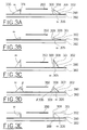
- Figures 3A 3b, 3d and 3E show cross-sections of different embodiments of an antenna according to the invention.
- the cross-sections may, for example, be of an antenna according to Figure 1 or 2 .
- the radiating antenna elements are here also illustrated as aperture-coupled patches 350 which are thus positioned a little way away from a ground plane 390. Only the ground planes 390 are shown with substrates 392.
- Figure 3A shows a metal frame 301 with a first side 330 angled away from the radiating antenna element 350 with the angle ⁇ 305 between the side and the normal 309 (which in this case is the same as the second side 331 of the metal frame) of the ground plane, which normal passes through the upper edge 308 of the metal frame.
- the angle ⁇ 305 (-90° ⁇ ⁇ ⁇ 180°) is a parameter which determines the lobe width (within the range 90° to 0° the lobe is widened and from 90° upwards the lobe is compressed) and is shown as positive in Figures 3-6 and has been shown as 0° in Figures 1 and 2 .
- the cavity 302 which arises when the angle ⁇ 305 is greater than zero may be air, a support substrate or any other dielectric.
- the metal frame 301 may also be made entirely of metal which means that the cavity 302 is filled with metal.
- Figure 3B shows the metal frame 301 as shorter than the distance between the ground plane 390 and the patch 350, that is to say that the upper edge 308 of the metal frame 301 lies between the ground plane 390 and a plane which is parallel to the ground plane and in which the radiating antenna element, the patch 350, mainly lies.
- Figure 3C shows the metal frame 301 as taller than the distance between the ground plane 390 and the patch 350.
- Figures 3A, 3D and 3E show metal frames 301, 303 with such a height that the upper edges 308 of the metal frames 301, 303 mainly lie in the same plane as that in which the patch 350 lies.
- a taller metal frame gives a wider antenna lobe.
- the metal frame 301 may be asymmetrical in height around the metal frame 302.
- the antenna lobe will then be directed in the direction in which the metal frame is taller.
- the antenna lobe can also be controlled by the metal frame 301 being positioned asymmetrically around the antenna element, in this example the patch 350, that is to say that one or two sides of a square metal frame is/are closer to the antenna element than the other two or three.
- the antenna lobe is turned in the direction in which the antenna element is closer to the metal frame.
- the antenna lobe can also be controlled by modifying the circumference of the metal frame, where a smaller circumference, that is to say the metal frame is closer to the antenna element, gives a wider/larger antenna lobe.
- Figure 3D shows that an angle ⁇ 306 (-180° ⁇ ⁇ ⁇ 90°), in this case shown as greater than 0°, between that side of the metal frame towards the patch 350 and the normal 309 of the ground plane, which normal passes through the upper edge 308 of the metal frame, may also be used for controlling the lobe (it is also possible, of course, that the angle ⁇ 306 may be negative with an absolute value which is less than the angle ⁇ 305).
- Figure 4 shows an example with a single-polarized dipole 451 as an antenna element above a ground plane 490.
- the metal walls 405 can be used in order to control the lobe width individually for each individual radiating antenna element 451 which, for example, forms part of an array antenna. In certain situations, it may be sufficient for a dual-polarized antenna element also to use only two metal walls.
- Figure 5 shows an example with a single-polarized dipole 551 above a ground plane 590, similar to the example according to Figure 4 .
- a metal frame 501 according to the invention for controlling the antenna lobe is shown.
- Figure 6 shows an example with a dual-polarized dipole 651 above a ground plane 690 with a metal frame 601 according to the invention.
- the invention relates to antennas, and in particular microwave antennas such as microstrip antennas, and control of their lobes and increasing the isolation between the polarizations in the case of use of dual-polarized antenna elements. It has been shown above how a metal frame positioned on the ground plane of the antenna, around the projection of each radiating antenna element, can, by means of the positioning and shape of the metal frame, control the width and direction of the antenna lobe and also eliminate or reduce cross-coupling between the polarizations in dual-polarized antenna elements.
Landscapes
- Engineering & Computer Science (AREA)
- Computer Networks & Wireless Communication (AREA)
- Variable-Direction Aerials And Aerial Arrays (AREA)
- Waveguide Aerials (AREA)
- Details Of Aerials (AREA)
Abstract
Description
- The present invention relates to devices for and/or comprised in antennas, in particular microwave antennas, with which control and modification of the antenna lobe can be carried out. The invention also relates to devices for and/or comprised in antennas, in particular microwave antennas, with which coupling between the polarizations in dual-polarized radiating antenna elements can be reduced or completely avoided.
- The development of mobile telephony has created a need for simple and inexpensive mass production of antennas for, inter alia, base stations. Mobile telephony utilizes frequency ranges which lie within the microwave range, for which reason a type of antenna which is often used is microstrip antennas. Microstrip antennas consist of radiating antenna elements which are mounted in front of a ground plane. A base station usually uses a number of antennas in order to cover a cell. Different mobile telephony operators make use of different algorithms for cell planning, which results in a demand for antennas with, inter alia, different lobe widths. One known way of controlling the lobe width of a microstrip antenna is to modify the dimensions of the ground plane. If a large lobe width is desired, the size of the ground plane is limited. A major disadvantage of the size of the ground plane being reduced in the case of a large lobe width being desired is that this also limits the possibility of, for example, using a microstrip distribution network as a feeder network for the radiating elements. Therefore, antennas with wide lobes cannot on the whole use microstrip distribution networks as feeder networks or they can use them only to an extremely limited extent. If desired, antennas with narrow lobes can in most cases use microstrip distribution networks as feeder networks, which is advantageous as far as, inter alia, manufacturing aspects and therefore the costs of these antennas. Another major disadvantage of modifying the size of the ground plane in order to control the lobe width is that the shape and size of the antenna are influenced, that is to say that different antennas must be designed and subsequently manufactured for different desired lobe widths. Modifying the size and shape of an antenna results in a number of consequential problems such as, for example, the need for different weather protection (radomes) and modified mounting arrangements.
- A microstrip antenna controlling the lobe by placing the radiating patch inside a metallic cavity is disclosed in
US 5434581 . - In order to achieve better and more reliable coverage, which is of particular importance within mobile telephony, use is made of polarization diversity. Antennas, in particular microwave antennas, advantageously use dual-polarized radiation elements as this reduces the size and production costs of the antenna compared with the use of single-polarized radiation elements. A requirement has arisen, in particular within mobile telephony, for antennas with ±45° polarization because this type of polarization has proved to have many advantages, such as more symmetrical propagation/attenuation, in relation to 0/90° polarization. Unfortunately, it has proved to be difficult, in relation to 0/90° polarization antennas, to manufacture ±45° polarization antennas, and in particular microstrip antennas, with dual-polarized radiation elements which have satisfactory isolation between the polarizations, that is to say low cross-coupling.
- One object of the invention is to indicate a device for and/or comprised in antennas, in particular microwave antennas such as microstrip antennas, for controlling the lobe width of the antenna and if appropriate the lobe direction without having to modify the size of the ground plane of the antenna.
- Another object of the invention is to indicate a device for and/or comprised in antennas, in particular microwave antennas such as microstrip antennas, which completely or partially suppresses the occurrence of cross-coupling between the polarizations in dual-polarized radiation elements.
- According to the invention, the abovementioned objects are achieved by a device for and/or comprised in antennas, in particular microwave antennas such as microstrip antennas, for controlling the antenna lobe and completely or partially suppressing cross-coupling between the polarizations in dual-polarized antenna elements. A metal frame, the sides of which can be angled for a desired lobe width, is positioned around each antenna element on top of the ground plane of the antenna. The shape and positioning of the metal frame around the antenna element also control the antenna lobe. In this way, the antenna lobe can be controlled in the desired manner irrespective of the size of the ground plane of the antenna, which depends, for example, on a desired microstrip distribution network for the antenna.
- According to the invention, the abovementioned objects are also achieved by means of an antenna for receiving and transmitting electromagnetic signals mainly within the microwave frequency range with an antenna lobe in a direction relative to the normal of the antenna. The antenna comprises a ground plane and at least one antenna element. The ground plane comprises a first side and a second side. The antenna element is mounted at a predefined distance from the first side of the ground plane and the antenna element is fed by feed means from the second side of the ground plane. An antenna element may be, for example, probe-fed or aperture-fed.
- According to the invention, a metal frame is arranged on the first side of the ground plane around the projection of the antenna element on the first side of the ground plane in order thus to control the size and direction of the antenna lobe with the shape and positioning of the metal frame on the first side of the ground plane. The antenna element is suitably arranged in connection with the metal frame, that is to say that the metal frame may also serve as a holder for the antenna element. The metal frame suitably comprises a first and a second side. The second side of the metal frame faces the projection of the antenna element. The first and second side of the metal frame are suitably electrically interconnected at least along one edge which forms a line along the metal frame. The edge is suitably an upper edge/edge-line on the metal frame.
- So as to improve the possibility of controlling the antenna lobe, a first angle may be formed at the edge between the first side of the metal frame and the normal of the first side of the ground plane through the edge. The first angle is considered positive from the normal of the first side of the ground plane through the edge and away from the antenna element. A second angle may also be formed and, that being the case, it is formed at the edge between the second side of the metal frame and the normal of the first side of the ground plane through the edge. The second angle is considered positive from the normal of the first side of the ground plane through the edge and towards the antenna element. The first angle may be positive and greater than zero in order thus to control the antenna lobe. The second angle may be positive and greater than zero in order thus to control the antenna lobe. The angles may each be modified with the other equal to zero or with both angles other than zero. In certain applications, it may be advantageous that the first angle is positive (greater than zero) and that the second angle is negative (less than zero) with an absolute value which is smaller than the first angle, in order thus to control the antenna lobe. In other applications, it may be advantageous that the second angle is positive and that the first angle is negative with an absolute value which is smaller than the second angle, in order thus to control the antenna lobe. In some cases, it may be advantageous if at least one angle changes in value at least once around the metal frame in order thus to control the antenna lobe.
- The edge may suitably lie between the ground plane and a parallel plane in which the antenna element mainly lies. Alternatively, the edge lies mainly in a plane in which the antenna element lies and which is parallel to the ground plane. Alternatively, the edge lies beyond a plane in which the antenna element lies, in relation to the parallel ground plane. It is also conceivable that the distance of the edge from the ground plane along the normal of the ground plane varies around the metal frame in order thus to control the antenna lobe, which means that the edge may lie below, above or in the same plane as the antenna element (or another combination with one or more of the alternatives) around the course of the metal frame.
- The metal frame may be electrically connected to or electrically isolated from the ground plane. The metal frame may mainly be centered around the projection of the antenna element on the first side of the ground plane or arranged asymmetrically around the projection of the antenna element on the first side of the ground plane depending upon the application. In an embodiment of the invention, the antenna is a microstrip antenna where the antenna element is an aperture-coupled patch which, if appropriate, is also, for example, ±45° dual-polarized. The edge line of the metal frame is parallel or at right angles to the polarization or polarizations of the antenna element. In certain applications which use square patches, it may be suitable if the edge line of the metal frame forms a square. The antenna may advantageously be an array antenna with at least two antenna elements each having its own metal frame.
- The abovementioned objects are also achieved by means of an array antenna for receiving and transmitting electromagnetic signals mainly within the microwave frequency range with an antenna lobe in a direction relative to the normal of the array antenna. The array antenna comprises a ground plane and at least two microstrip antenna elements. The ground plane comprises a first side and a second side. The microstrip antenna elements are mounted at a predefined distance from (in front of/above) the first side of the ground plane and are ±45° dual-polarized aperture-coupled patches which are fed by a microstrip distribution network from the second side of the ground plane. According to the invention, a metal frame is arranged on the first side of the ground plane around the projection of each microstrip antenna element on the first side of the ground plane. The size and direction of the antenna lobe are controlled by means of the shape and positioning of the metal frame on the first side of the ground plane. The metal frame comprises a first and a second side with the second side of the metal frame facing the projection of the respective microstrip antenna element. The first and second side of the metal frame are electrically interconnected at least along one edge which forms a line along the metal frame. The edge is suitably an upper edge/edge-line on the metal frame. A first angle is formed at the edge between the first side of the metal frame and the normal of the first side of the ground plane through the edge and a second angle is formed at the edge between the second side of the metal frame and the normal of the first side of the ground plane through the edge. In certain applications, it is advantageous that at least one of the first and the second angles changes around the metal frame. The edge of the metal frame which forms a line around the metal frame may be equidistant from the microstrip antenna element along the whole line, or the metal frame is positioned asymmetrically around the projection of the microstrip antenna element in order thus to control the direction of the antenna lobe. The respective metal frames of different microstrip antenna elements are not necessarily the same.
- The invention has a number of advantages compared with the prior art as far as antennas are concerned, and in particular microwave antennas such as microstrip antennas which use microstrip distribution networks as feeder networks for the radiating elements of the antenna. The radiating elements of the antenna may be, for example, slots, aperture-coupled patches or dipoles. The invention controls the lobe width (the lobe size) by varying only the inclination, the height or the position (or a combination of these) of the sides of a metal frame which is positioned around each radiating element in the antenna. The invention also controls the direction of the antenna lobe in relation to the normal of the antenna by determining the centering of the antenna element in the metal frame or by means of different height and angles on opposite sides on the metal frame. In this way, an antenna can be designed and subsequently manufactured in large series and can then, depending on demand, be customized simply with regard to, inter alia, the lobe width at a late stage of production. The invention also eliminates partially or completely cross-coupling between polarizations in dual-polarized radiation elements. This is achieved by the invention creating a mirror-symmetrical environment for each polarization direction, the result of which is that no component in the second polarization can be excited. In this way, the use of microstrip antennas with ±45° dual-polarized radiating antenna elements is made possible. According to the invention, cross-coupling is also reduced between different antenna elements in an array antenna. This means that the invention is of interest with regard to, for example, base station antennas for mobile telephone systems, which are manufactured in great quantities.
- The invention will be described in greater detail below in a non-limiting manner for the purpose of clarification, with reference to the attached figures, in which
- Fig. 1
- shows a front view of a ±45° polarized microstrip array antenna according to the invention with aperture-coupled dual- polarized patches,
- Fig. 2
- shows a side view of the antenna in
Figure 1 , - Figs 3a, 3b, 3d and 3e
- show cross-sections of different embodiments of antennas according to the invention,
- Fig 3c
- shows an antenna which is not part of the invention
- Fig. 4
- shows a view of a single-polarized antenna according to the invention with a dipole as radiation element,
- Fig. 5
- shows a front view of a single-polarized antenna according to the invention with a dipole as radiation element,
- Fig. 6
- shows a front view of a dual-polarized antenna according to the invention with a dipole as radiation element.
- In order to illustrate the invention, a few examples of its application are to be described in the following with reference to
Figures 1 to 6 . -
Figure 1 shows a front view of a part of an array antenna designed according to the invention. The array antenna in the figure is a ±45° polarized microstrip antenna which may suitably be used as a base station antenna in a mobile telephone system. In this example, aperture-coupled dual-polarizedpatches 150 are used as radiating antenna elements. Thepatches 150 lie above, for example, slots in aground plane 190. According to the invention, ametal frame 100 lies around the radiatingantenna elements 150. The edge of thepatch 150 lies in the order of λ/20 to λ/2 (where λ is the wavelength) from themetal frame 100. Themetal frame 100 may either be electrically connected to theground plane 190 or electrically isolated from theground plane 190, depending on the desired antenna characteristics. -
Figure 2 shows a side view of a microstrip antenna according to the invention. The side view may, for example, be of an antenna similar to the antenna according toFigure 1 . Here, a microstrip distribution network is shown, comprising adistribution network 294, aground plane 290 and asupport substrate 292. The radiatingantenna element 250, here shown as an aperture-coupledpatch 250, usually also has asupport substrate 252. Apatch 250 usually lies in the order of λ\10 from theground plane 290. According to the invention, ametal frame 200 is positioned in relation to theground plane 290 around the projection of the respectiveradiating antenna element 250 on the ground plane. Theupper edge 208 of themetal frame 200 is shown here in side view lying between theground plane 290 and thepatch 250. Themetal frame 200 is suitably of a height of the order of λ/40 to λ/4 above theground plane 290, which means that theupper edge 208 of themetal frame 200 will lie between theground plane 290 and thepatch 250, in the same plane as thepatch 250 or on the other side, that is to say above/in front of, thepatch 250. -
Figures 3A 3b, 3d and 3E show cross-sections of different embodiments of an antenna according to the invention. The cross-sections may, for example, be of an antenna according toFigure 1 or 2 . The radiating antenna elements are here also illustrated as aperture-coupledpatches 350 which are thus positioned a little way away from aground plane 390. Only the ground planes 390 are shown withsubstrates 392.Figure 3A shows ametal frame 301 with a first side 330 angled away from the radiatingantenna element 350 with the angle α 305 between the side and the normal 309 (which in this case is the same as thesecond side 331 of the metal frame) of the ground plane, which normal passes through theupper edge 308 of the metal frame. The angle α 305 (-90° < α < 180°) is a parameter which determines the lobe width (within the range 90° to 0° the lobe is widened and from 90° upwards the lobe is compressed) and is shown as positive inFigures 3-6 and has been shown as 0° inFigures 1 and 2 . Thecavity 302 which arises when the angle α 305 is greater than zero may be air, a support substrate or any other dielectric. Themetal frame 301 may also be made entirely of metal which means that thecavity 302 is filled with metal. -
Figure 3B shows themetal frame 301 as shorter than the distance between theground plane 390 and thepatch 350, that is to say that theupper edge 308 of themetal frame 301 lies between theground plane 390 and a plane which is parallel to the ground plane and in which the radiating antenna element, thepatch 350, mainly lies.Figure 3C shows themetal frame 301 as taller than the distance between theground plane 390 and thepatch 350.Figures 3A, 3D and 3E show metal frames 301, 303 with such a height that theupper edges 308 of the metal frames 301, 303 mainly lie in the same plane as that in which thepatch 350 lies. A taller metal frame gives a wider antenna lobe. Themetal frame 301 may be asymmetrical in height around themetal frame 302. The antenna lobe will then be directed in the direction in which the metal frame is taller. According to the invention, the antenna lobe can also be controlled by themetal frame 301 being positioned asymmetrically around the antenna element, in this example thepatch 350, that is to say that one or two sides of a square metal frame is/are closer to the antenna element than the other two or three. The antenna lobe is turned in the direction in which the antenna element is closer to the metal frame. The antenna lobe can also be controlled by modifying the circumference of the metal frame, where a smaller circumference, that is to say the metal frame is closer to the antenna element, gives a wider/larger antenna lobe. -
Figure 3D shows that an angle β 306 (-180° < β < 90°), in this case shown as greater than 0°, between that side of the metal frame towards thepatch 350 and the normal 309 of the ground plane, which normal passes through theupper edge 308 of the metal frame, may also be used for controlling the lobe (it is also possible, of course, that the angle β 306 may be negative with an absolute value which is less than the angle α 305). -
Figure 4 shows an example with a single-polarizeddipole 451 as an antenna element above aground plane 490. Here, there is a requirement for only twometal walls 405 according to the invention for controlling the lobe width. Here, themetal walls 405 can be used in order to control the lobe width individually for each individualradiating antenna element 451 which, for example, forms part of an array antenna. In certain situations, it may be sufficient for a dual-polarized antenna element also to use only two metal walls. -
Figure 5 shows an example with a single-polarizeddipole 551 above aground plane 590, similar to the example according toFigure 4 . Here, ametal frame 501 according to the invention for controlling the antenna lobe is shown. -
Figure 6 shows an example with a dual-polarizeddipole 651 above aground plane 690 with ametal frame 601 according to the invention. - The invention relates to antennas, and in particular microwave antennas such as microstrip antennas, and control of their lobes and increasing the isolation between the polarizations in the case of use of dual-polarized antenna elements. It has been shown above how a metal frame positioned on the ground plane of the antenna, around the projection of each radiating antenna element, can, by means of the positioning and shape of the metal frame, control the width and direction of the antenna lobe and also eliminate or reduce cross-coupling between the polarizations in dual-polarized antenna elements.
- The invention is not limited to the embodiments indicated above but can be modified within the scope of the patent claims which follow.
Claims (18)
- Microstrip antenna for receiving and transmitting electromagnetic signals mainly within the microwave frequency range with an antenna lobe in a direction relative to the normal of the microstrip antenna, which microstrip antenna comprises a ground plane (190, 290, 390) and at least one dual polarized antenna element (150, 250, 350), the ground plane (190, 290, 390) comprising a first side and a second side, the antenna element (150, 250, 350) being mounted at a predefined distance from the first side of the ground plane, and a metal frame (100, 200, 301, 303) being arranged on the first side of the ground plane around the projection of the antenna element on the first side of the ground plane, said metal frame (100, 200, 301, 303) comprising a first and a second side where the second side of the metal frame faces the projection of the antenna element,
characterized in
that the first and second side of the metal frame are electrically interconnected at least along one edge (208, 308) which forms an upper edge line along the metal frame, that the dual polarized antenna element is fed by feed means (294) from the second side of the ground plane, the metal frame serving the purpose of controlling the size and direction of the antenna lobe with the shape and positioning thereof on the first side of the ground plane, and in that a first angle (305) is formed at the edge (308) between the first side of the metal frame and the normal (309) of the first side of the ground plane through the edge, where the first angle is considered positive from the normal of the first side of the ground plane through the edge and away from the dual-polarized antenna element, that a second angle (306) is formed at the edge (308) between the second side of the metal frame and the normal (309) of the first side of the ground plane through the edge, where the second angle is considered positive from the normal of the first side of the ground plane through the edge and towards the dual-polarized antenna element, that the first angle is greater than zero or the second angle is greater than zero,
in order thus to control the width of the antenna lobe, and in that the upper edge line (308) lies between the ground plane (190, 290, 390) and a parallel plane in which the antenna element (150, 250, 350) mainly lies, or lies mainly in a plane in which the dual-polarized antenna element (150, 250, 350) lies and which is parallel to the ground plane (190, 290, 390). - Microstrip antenna according to claim 1,
characterized in
that when the first angle is greater than zero, the second angle is greater than zero or negative with an absolute value which is smaller than the first angle. - Microstrip antenna according to claim 1,
characterized in
that when the second angle is greater than zero, the first angle is greater than zero or negative with an absolute value which is smaller than the second angle. - Microstrip antenna according to any one of the preceding claims,
characterized in
that the distance of the edge (308) from the ground plane (190, 290, 390) along the normal of the ground plane varies around the metal frame in order thus to control the antenna lobe. - Microstrip antenna according to any one of claims 1-4,
characterized in
that the metal frame is electrically connected to the ground plane (190, 290, 390). - Microstrip antenna according to any one of claims 1-4,
characterized in
that the metal frame is electrically isolated from the ground plane (190, 290, 390). - Microstrip antenna according to any one of claims 1-6,
characterized in
that the metal frame is mainly centered around the projection of the antenna element on the first side of the ground plane. - Microstrip antenna according to any one of claims 1-6,
characterized in
that the metal frame is arranged asymmetrically around the projection of the antenna element on the first side of the ground plane. - Microstrip antenna according to any one of claims 1-8,
characterized in
that the antenna element (150, 250, 350) is an aperture-coupled patch. - Microstrip antenna according to any one of claims 1-9,
characterized in
that the edge line of the metal frame is parallel or at right angles to the polarization or polarizations of the antenna element (150, 250, 350). - Microstrip antenna according to any one of claims 1-10,
characterized in
that the edge line of the metal frame forms a square. - Microstrip antenna according to any one of claims 1-11,
characterized in
that the microstrip antenna is an array antenna with at least two antenna elements (150, 250, 350) each having its own metal frame. - Microstrip antenna according to any one of claims 1-12,
characterized in
that the antenna element (150, 250, 350) is a ±45° dual-polarized aperture-coupled patch. - Array antenna for receiving and transmitting electromagnetic signals mainly within the microwave frequency range with an antenna lobe in a direction relative to the normal of the array antenna, which array antenna comprises a ground plane and at least two microstrip antenna elements, where the ground plane comprises a first side and a second side, the microstrip antenna elements are mounted at a predefined distance from the first side of the ground plane and are ±45° dual-polarized aperture-coupled patches, a metal frame being arranged on the first side of the ground plane around the projection of each microstrip antenna element on the first side of the ground plane, where the metal frame comprises a first and a second side with the second side of the metal frame facing the projection of the respective microstrip antenna element,
characterized in
that the patches are fed by a microstrip distribution network from the second side of the ground plane, that the first and second side of the metal frame are electrically interconnected at least along one edge which forms an upper edge line along the metal frame, and where a first angle is formed at the edge between the first side of the metal frame and the normal of the first side of the ground plane through the edge and where a second angle is formed at the edge between the second side of the metal frame and the normal of the first side of the ground plane through the edge, the metal frame serving the purpose of controlling the size and direction of the antenna lobe by means of the shape and positioning of said metal frame on the first side of the ground plane, that said first angle is greater than zero or said second angle is greater than zero, or both said first and second angles are greater than zero, and in that the upper edge line (308) lies between the ground plane (190, 290, 390) and a parallel plane in which the antenna element (150, 250, 350) mainly lies, or lies mainly in a plane in which the antenna element (150, 250, 350) lies and which is parallel to the ground plane (190, 290, 390). - Array antenna according to claim 14,
characterized in that
at least one of the first and the second angles changes around the metal frame. - Array antenna according to either claim 14 or 15,
characterized in
that the edge of the metal frame which forms a line around the metal frame is equidistant from the microstrip antenna element along the whole line. - Array antenna according to any one of claims 14-16,
characterized in
that the metal frame of at least one microstrip antenna element is positioned asymmetrically around the projection of the microstrip antenna element in order thus to control the direction of the antenna lobe. - Array antenna according to any one of claims 14-18,
characterized in
that the respective metal frames of different microstrip antenna elements are not the same.
Applications Claiming Priority (3)
| Application Number | Priority Date | Filing Date | Title |
|---|---|---|---|
| SE9700536A SE508513C2 (en) | 1997-02-14 | 1997-02-14 | Microstrip antenna as well as group antenna |
| SE9700536 | 1997-02-14 | ||
| PCT/SE1998/000254 WO1998036473A1 (en) | 1997-02-14 | 1998-02-13 | Microstrip antenna and array antenna |
Publications (2)
| Publication Number | Publication Date |
|---|---|
| EP0960452A1 EP0960452A1 (en) | 1999-12-01 |
| EP0960452B1 true EP0960452B1 (en) | 2010-11-24 |
Family
ID=20405808
Family Applications (1)
| Application Number | Title | Priority Date | Filing Date |
|---|---|---|---|
| EP98904493A Expired - Lifetime EP0960452B1 (en) | 1997-02-14 | 1998-02-13 | Microstrip antenna and array antenna |
Country Status (9)
| Country | Link |
|---|---|
| US (1) | US6023244A (en) |
| EP (1) | EP0960452B1 (en) |
| JP (1) | JP4223564B2 (en) |
| CN (1) | CN1252175A (en) |
| AU (1) | AU6234598A (en) |
| CA (1) | CA2280759A1 (en) |
| DE (1) | DE69842016D1 (en) |
| SE (1) | SE508513C2 (en) |
| WO (1) | WO1998036473A1 (en) |
Families Citing this family (73)
| Publication number | Priority date | Publication date | Assignee | Title |
|---|---|---|---|---|
| DE19823750A1 (en) * | 1998-05-27 | 1999-12-09 | Kathrein Werke Kg | Antenna array with several primary radiator modules arranged vertically one above the other |
| DE19823749C2 (en) * | 1998-05-27 | 2002-07-11 | Kathrein Werke Kg | Dual polarized multi-range antenna |
| US6181281B1 (en) * | 1998-11-25 | 2001-01-30 | Nec Corporation | Single- and dual-mode patch antennas |
| US6469627B1 (en) | 2000-02-11 | 2002-10-22 | Marconi Communications Inc. | Mounting clip having a wireless communication device |
| US6720865B1 (en) | 2000-02-11 | 2004-04-13 | Marconi Intellectual Property (Us) | Resilient member with wireless communication device |
| US6580357B1 (en) | 2000-02-11 | 2003-06-17 | Marconi Communications Inc. | Handle tag for identification of a container |
| US6778088B1 (en) | 2000-02-11 | 2004-08-17 | Marconi Intellectual Property (Us) Inc. | Deployable identification device |
| DE10012809A1 (en) * | 2000-03-16 | 2001-09-27 | Kathrein Werke Kg | Dual polarized dipole array antenna has supply cable fed to supply point on one of two opposing parallel dipoles, connecting cable to supply point on opposing dipole |
| US6628237B1 (en) | 2000-03-25 | 2003-09-30 | Marconi Communications Inc. | Remote communication using slot antenna |
| US6734796B2 (en) | 2000-04-04 | 2004-05-11 | Ian J. Forster | Self-check for a detector detecting the proximity of a transportation vessel |
| US6281797B1 (en) * | 2000-04-04 | 2001-08-28 | Marconi Data Systems Inc. | Method and apparatus for detecting a container proximate to a transportation vessel hold |
| US6646555B1 (en) | 2000-07-18 | 2003-11-11 | Marconi Communications Inc. | Wireless communication device attachment and detachment device and method |
| US6483473B1 (en) | 2000-07-18 | 2002-11-19 | Marconi Communications Inc. | Wireless communication device and method |
| US7098850B2 (en) * | 2000-07-18 | 2006-08-29 | King Patrick F | Grounded antenna for a wireless communication device and method |
| US6806842B2 (en) * | 2000-07-18 | 2004-10-19 | Marconi Intellectual Property (Us) Inc. | Wireless communication device and method for discs |
| DE10064129B4 (en) * | 2000-12-21 | 2006-04-20 | Kathrein-Werke Kg | Antenna, in particular mobile radio antenna |
| KR100403764B1 (en) * | 2000-12-28 | 2003-10-30 | 주식회사 하이닉스반도체 | Polarization Diversity Applicable Smart Antenna |
| US20020122820A1 (en) * | 2001-01-16 | 2002-09-05 | Hildebrand William H. | Soluble MHC artificial antigen presenting cells |
| US6545606B2 (en) | 2001-01-25 | 2003-04-08 | The United States Of America As Represented By The Secretary Of The Navy | Device and method for alerting to the need to recover something, identifying it, and determining its location for purposes of recovery |
| US20020130817A1 (en) * | 2001-03-16 | 2002-09-19 | Forster Ian J. | Communicating with stackable objects using an antenna array |
| DE10150150B4 (en) | 2001-10-11 | 2006-10-05 | Kathrein-Werke Kg | Dual polarized antenna array |
| US7230954B2 (en) * | 2001-12-04 | 2007-06-12 | Delphi Technologies, Inc. | Cross link intra-vehicular data communication using a field coupled transmission line |
| WO2003050917A1 (en) * | 2001-12-07 | 2003-06-19 | Skycross, Inc. | Multiple antenna diversity for wireless lan applications |
| BG64431B1 (en) * | 2001-12-19 | 2005-01-31 | Skygate International Technology N.V. | Antenna element |
| GB0200585D0 (en) * | 2002-01-11 | 2002-02-27 | Csa Ltd | Antenna with adjustable beam direction |
| AU2003233113A1 (en) * | 2002-04-24 | 2003-11-10 | Marconi Intellectual Property (Us) Inc | Energy source recharging device and method |
| AU2003233026A1 (en) * | 2002-04-24 | 2003-11-10 | Marconi Intellectual Property (Us) Inc | Rechargeable interrogation reader device and method |
| EP1500043B1 (en) | 2002-04-24 | 2008-07-30 | Mineral Lassen LLC | Manufacturing method for a wireless communication device and manufacturing apparatus |
| US7123204B2 (en) * | 2002-04-24 | 2006-10-17 | Forster Ian J | Energy source communication employing slot antenna |
| US6847912B2 (en) * | 2002-05-07 | 2005-01-25 | Marconi Intellectual Property (Us) Inc. | RFID temperature device and method |
| US7224273B2 (en) * | 2002-05-23 | 2007-05-29 | Forster Ian J | Device and method for identifying a container |
| WO2003103087A2 (en) * | 2002-06-04 | 2003-12-11 | Skycross, Inc. | Wideband printed monopole antenna |
| US6888510B2 (en) * | 2002-08-19 | 2005-05-03 | Skycross, Inc. | Compact, low profile, circular polarization cubic antenna |
| US6950066B2 (en) * | 2002-08-22 | 2005-09-27 | Skycross, Inc. | Apparatus and method for forming a monolithic surface-mountable antenna |
| US7705793B2 (en) * | 2004-06-10 | 2010-04-27 | Raysat Antenna Systems | Applications for low profile two way satellite antenna system |
| US7379707B2 (en) * | 2004-08-26 | 2008-05-27 | Raysat Antenna Systems, L.L.C. | System for concurrent mobile two-way data communications and TV reception |
| US20110215985A1 (en) * | 2004-06-10 | 2011-09-08 | Raysat Antenna Systems, L.L.C. | Applications for Low Profile Two Way Satellite Antenna System |
| US7911400B2 (en) * | 2004-01-07 | 2011-03-22 | Raysat Antenna Systems, L.L.C. | Applications for low profile two-way satellite antenna system |
| US8761663B2 (en) | 2004-01-07 | 2014-06-24 | Gilat Satellite Networks, Ltd | Antenna system |
| US20060273965A1 (en) * | 2005-02-07 | 2006-12-07 | Raysat, Inc. | Use of spread spectrum for providing satellite television or other data services to moving vehicles equipped with small size antenna |
| DE602004012705T2 (en) * | 2004-02-20 | 2008-07-17 | Alcatel Lucent | Dual polarized antenna module |
| TWI304664B (en) * | 2004-06-30 | 2008-12-21 | Hon Hai Prec Ind Co Ltd | Antenna |
| US20070053314A1 (en) * | 2004-08-26 | 2007-03-08 | Yoel Gat | Method and apparatus for providing satellite television and other data to mobile antennas |
| US20070001914A1 (en) * | 2004-08-26 | 2007-01-04 | Raysat, Inc. | Method and apparatus for incorporating an antenna on a vehicle |
| US20060273967A1 (en) * | 2004-08-26 | 2006-12-07 | Raysat, Inc. | System and method for low cost mobile TV |
| US20100183050A1 (en) * | 2005-02-07 | 2010-07-22 | Raysat Inc | Method and Apparatus for Providing Satellite Television and Other Data to Mobile Antennas |
| US20100218224A1 (en) * | 2005-02-07 | 2010-08-26 | Raysat, Inc. | System and Method for Low Cost Mobile TV |
| US7403158B2 (en) * | 2005-10-18 | 2008-07-22 | Applied Wireless Identification Group, Inc. | Compact circular polarized antenna |
| US7720437B2 (en) * | 2005-12-08 | 2010-05-18 | University Of South Florida | Zero-order energy smart antenna and repeater |
| FR2907264A1 (en) * | 2006-10-16 | 2008-04-18 | Alcatel Sa | DECOUPLING NETWORKS OF RADIANT ELEMENTS OF AN ANTENNA |
| CN101478079B (en) * | 2008-01-04 | 2012-10-10 | 华硕电脑股份有限公司 | Array antenna and electronic device using same |
| CN101990725B (en) * | 2008-02-04 | 2014-08-20 | Agc汽车美洲研发公司 | Multi-Element Cavity Coupled Antenna |
| US20090231186A1 (en) * | 2008-02-06 | 2009-09-17 | Raysat Broadcasting Corp. | Compact electronically-steerable mobile satellite antenna system |
| JP2009290846A (en) * | 2008-06-02 | 2009-12-10 | Yupiteru Corp | Microwave detector |
| CN101599579B (en) * | 2008-06-05 | 2016-08-10 | 京信通信系统(中国)有限公司 | High cross polarization ratio antenna and dual-polarization radiating unit thereof |
| US20100109840A1 (en) * | 2008-10-31 | 2010-05-06 | Robert Schilling | Radio Frequency Identification Read Antenna |
| CN101847783B (en) * | 2009-03-25 | 2013-01-30 | 华为技术有限公司 | Dual-polarized element antenna |
| CN102498615A (en) * | 2009-08-25 | 2012-06-13 | 莱尔德技术股份有限公司 | Antenna array with baffle box to reduce mutual coupling |
| US9030364B2 (en) | 2010-09-07 | 2015-05-12 | Kunjie Zhuang | Dual-polarized microstrip antenna |
| CN102856628B (en) * | 2011-03-08 | 2016-06-08 | 中国空空导弹研究院 | A kind of millimeter wave/conformal antenna of infrared dual mode complex probe |
| FR2975537B1 (en) * | 2011-05-17 | 2013-07-05 | Thales Sa | RADIANT ELEMENT FOR AN ACTIVE NETWORK ANTENNA CONSISTING OF BASIC TILES |
| US9368859B2 (en) | 2012-10-09 | 2016-06-14 | Saab Ab | Method for integrating an antenna with a vehicle fuselage |
| US9748656B2 (en) * | 2013-12-13 | 2017-08-29 | Harris Corporation | Broadband patch antenna and associated methods |
| US9912060B2 (en) * | 2015-01-09 | 2018-03-06 | The United States Of America As Represented By The Secretary Of The Army | Low-profile, tapered-cavity broadband antennas |
| US9865925B2 (en) * | 2015-01-09 | 2018-01-09 | The United States Of America As Represented By The Secretary Of The Army | Low-profile cavity broadband antennas having an anisotropic transverse resonance condition |
| JP6214582B2 (en) * | 2015-02-26 | 2017-10-18 | 東芝テック株式会社 | Antenna and method for adjusting antenna characteristics |
| CN105161859A (en) * | 2015-07-08 | 2015-12-16 | 武汉虹信通信技术有限责任公司 | Wideband multiport base station antenna radiation boundary |
| WO2017091307A1 (en) * | 2015-11-25 | 2017-06-01 | Commscope Technologies Llc | Phased array antennas having decoupling units |
| US10008762B2 (en) * | 2016-01-22 | 2018-06-26 | Fractus Antennas, S.L. | Wireless device including optimized antenna system on metal frame |
| CN110996496B (en) * | 2019-12-24 | 2025-07-08 | 广东纳睿雷达科技股份有限公司 | Circuit board, antenna assembly and dual polarized antenna |
| CN111276800B (en) * | 2020-02-04 | 2021-10-22 | Oppo广东移动通信有限公司 | Dual-band mmWave antenna modules and electronic equipment |
| US11863246B2 (en) * | 2020-03-18 | 2024-01-02 | Avista Edge, Inc. | Achieving polarization diversity and directionality using predetermined phases and amplitude |
| CN111769352B (en) * | 2020-06-12 | 2021-09-24 | 中国船舶重工集团公司第七二四研究所 | Antenna unit design method for changing polarization by adjusting frame structure parameters |
Family Cites Families (17)
| Publication number | Priority date | Publication date | Assignee | Title |
|---|---|---|---|---|
| US3982824A (en) * | 1971-12-01 | 1976-09-28 | Raytheon Company | Catoptric lens arrangement |
| AU523867B2 (en) * | 1978-03-29 | 1982-08-19 | Mcneil Lab Inc. | Substituted n-iminomethylpiperidines |
| DE2947986A1 (en) * | 1979-11-28 | 1981-06-04 | Siemens AG, 1000 Berlin und 8000 München | Near field Cassegrain antenna - has lobe widened by moving region of auxiliary reflector between horn radiator and collecting reflector |
| US4287518A (en) * | 1980-04-30 | 1981-09-01 | Nasa | Cavity-backed, micro-strip dipole antenna array |
| CA1263745A (en) * | 1985-12-03 | 1989-12-05 | Nippon Telegraph & Telephone Corporation | Shorted microstrip antenna |
| US4903033A (en) * | 1988-04-01 | 1990-02-20 | Ford Aerospace Corporation | Planar dual polarization antenna |
| US5001493A (en) * | 1989-05-16 | 1991-03-19 | Hughes Aircraft Company | Multiband gridded focal plane array antenna |
| SE465391B (en) * | 1990-07-24 | 1991-09-02 | Staffan Gunnarsson | VEHICLE DEVICE MAINTAINS POSITIONING BY AUTOMATIC FUELING |
| FR2698212B1 (en) * | 1992-11-16 | 1994-12-30 | Alcatel Espace | Radiant elementary source for array antenna and radiating sub-assembly comprising such sources. |
| US5444453A (en) * | 1993-02-02 | 1995-08-22 | Ball Corporation | Microstrip antenna structure having an air gap and method of constructing same |
| DE4323351A1 (en) * | 1993-07-13 | 1995-01-19 | Deutsche Aerospace | Antenna having a variable polar diagram |
| GB9402550D0 (en) * | 1994-02-10 | 1994-04-06 | Northern Telecom Ltd | Antenna |
| US5448252A (en) * | 1994-03-15 | 1995-09-05 | The United States Of America As Represented By The Secretary Of The Air Force | Wide bandwidth microstrip patch antenna |
| US5469181A (en) * | 1994-03-18 | 1995-11-21 | Celwave | Variable horizontal beamwidth antenna having hingeable side reflectors |
| KR0185962B1 (en) * | 1995-03-03 | 1999-05-15 | 구관영 | Antenna |
| WO1996034426A1 (en) * | 1995-04-24 | 1996-10-31 | Ntt Mobile Communications Network Inc. | Microstrip antenna |
| US5608414A (en) * | 1995-06-30 | 1997-03-04 | Martin Marietta Corp. | Heat rejecting spacecraft array antenna |
-
1997
- 1997-02-14 SE SE9700536A patent/SE508513C2/en not_active IP Right Cessation
-
1998
- 1998-02-13 CN CN98804001.8A patent/CN1252175A/en active Pending
- 1998-02-13 AU AU62345/98A patent/AU6234598A/en not_active Abandoned
- 1998-02-13 JP JP53566498A patent/JP4223564B2/en not_active Expired - Lifetime
- 1998-02-13 EP EP98904493A patent/EP0960452B1/en not_active Expired - Lifetime
- 1998-02-13 US US09/023,874 patent/US6023244A/en not_active Expired - Lifetime
- 1998-02-13 WO PCT/SE1998/000254 patent/WO1998036473A1/en not_active Ceased
- 1998-02-13 CA CA002280759A patent/CA2280759A1/en not_active Abandoned
- 1998-02-13 DE DE69842016T patent/DE69842016D1/en not_active Expired - Lifetime
Also Published As
| Publication number | Publication date |
|---|---|
| SE9700536D0 (en) | 1997-02-14 |
| JP2001511974A (en) | 2001-08-14 |
| CA2280759A1 (en) | 1998-08-20 |
| SE508513C2 (en) | 1998-10-12 |
| CN1252175A (en) | 2000-05-03 |
| WO1998036473A1 (en) | 1998-08-20 |
| DE69842016D1 (en) | 2011-01-05 |
| US6023244A (en) | 2000-02-08 |
| EP0960452A1 (en) | 1999-12-01 |
| AU6234598A (en) | 1998-09-08 |
| SE9700536L (en) | 1998-08-15 |
| JP4223564B2 (en) | 2009-02-12 |
Similar Documents
| Publication | Publication Date | Title |
|---|---|---|
| US6023244A (en) | Microstrip antenna having a metal frame for control of an antenna lobe | |
| CN113748572B (en) | Radiating element with angled feed stalk and base station antenna including the same | |
| US6335703B1 (en) | Patch antenna with finite ground plane | |
| CN1214488C (en) | Dual band antenna | |
| US10587034B2 (en) | Base station antennas with lenses for reducing upwardly-directed radiation | |
| EP3044831B1 (en) | Lensed based station antennas | |
| CA2699752C (en) | Base station antenna with beam shaping structures | |
| US7196674B2 (en) | Dual polarized three-sector base station antenna with variable beam tilt | |
| US6583760B2 (en) | Dual mode switched beam antenna | |
| US20170062940A1 (en) | Compact wideband dual polarized dipole | |
| EP1156549A2 (en) | A multi-band cellular basestation antenna | |
| Su et al. | A novel broadband polarization diversity antenna using a cross-pair of folded dipoles | |
| EP0973231A2 (en) | Dual polarization directional antenna having choke reflectors for minimizing side lobe | |
| EP1494313A1 (en) | Antenna system comprising a coverage antenna and an auxiliary antenna | |
| US20220353699A1 (en) | Base station antennas with sector splitting in the elevation plane based on frequency band | |
| CN116762237A (en) | Reflect array, reflect array design method and reflect array system | |
| WO1998036472A1 (en) | Dual-polarized antenna | |
| WO2025236984A1 (en) | Antenna unit, base station antenna, and communication device | |
| EP4220858A1 (en) | Radiating unit, antenna array, and network device | |
| US20240429620A1 (en) | Fence structure and base station antenna comprising the same | |
| JPH02113706A (en) | Antenna system | |
| CN112952403A (en) | Dual-polarized array antenna with rectangular flat-top forming | |
| Foo et al. | Dielectric fortification for wide-beamwidth patch arrays | |
| Abe et al. | A dual-polarized sub-THz Huygens' metasurface with a two-layer structure | |
| KR20200059492A (en) | Broadband array patch antenna for communication systems |
Legal Events
| Date | Code | Title | Description |
|---|---|---|---|
| PUAI | Public reference made under article 153(3) epc to a published international application that has entered the european phase |
Free format text: ORIGINAL CODE: 0009012 |
|
| 17P | Request for examination filed |
Effective date: 19990824 |
|
| AK | Designated contracting states |
Kind code of ref document: A1 Designated state(s): DE FR GB IT |
|
| RAP1 | Party data changed (applicant data changed or rights of an application transferred) |
Owner name: TELEFONAKTIEBOLAGET LM ERICSSON (PUBL) |
|
| 17Q | First examination report despatched |
Effective date: 20060905 |
|
| GRAP | Despatch of communication of intention to grant a patent |
Free format text: ORIGINAL CODE: EPIDOSNIGR1 |
|
| RIN1 | Information on inventor provided before grant (corrected) |
Inventor name: TORSTENSSON, LARS Inventor name: LINDQVIST, CHRISTER Inventor name: SNYGG, GOERAN |
|
| GRAS | Grant fee paid |
Free format text: ORIGINAL CODE: EPIDOSNIGR3 |
|
| GRAA | (expected) grant |
Free format text: ORIGINAL CODE: 0009210 |
|
| AK | Designated contracting states |
Kind code of ref document: B1 Designated state(s): DE FR GB IT |
|
| REG | Reference to a national code |
Ref country code: GB Ref legal event code: FG4D |
|
| REF | Corresponds to: |
Ref document number: 69842016 Country of ref document: DE Date of ref document: 20110105 Kind code of ref document: P |
|
| PLBE | No opposition filed within time limit |
Free format text: ORIGINAL CODE: 0009261 |
|
| STAA | Information on the status of an ep patent application or granted ep patent |
Free format text: STATUS: NO OPPOSITION FILED WITHIN TIME LIMIT |
|
| 26N | No opposition filed |
Effective date: 20110825 |
|
| REG | Reference to a national code |
Ref country code: DE Ref legal event code: R097 Ref document number: 69842016 Country of ref document: DE Effective date: 20110825 |
|
| REG | Reference to a national code |
Ref country code: FR Ref legal event code: PLFP Year of fee payment: 19 |
|
| REG | Reference to a national code |
Ref country code: FR Ref legal event code: PLFP Year of fee payment: 20 |
|
| PGFP | Annual fee paid to national office [announced via postgrant information from national office to epo] |
Ref country code: FR Payment date: 20170223 Year of fee payment: 20 Ref country code: DE Payment date: 20170227 Year of fee payment: 20 |
|
| PGFP | Annual fee paid to national office [announced via postgrant information from national office to epo] |
Ref country code: GB Payment date: 20170227 Year of fee payment: 20 |
|
| PGFP | Annual fee paid to national office [announced via postgrant information from national office to epo] |
Ref country code: IT Payment date: 20170223 Year of fee payment: 20 |
|
| REG | Reference to a national code |
Ref country code: DE Ref legal event code: R071 Ref document number: 69842016 Country of ref document: DE |
|
| REG | Reference to a national code |
Ref country code: GB Ref legal event code: PE20 Expiry date: 20180212 |
|
| PG25 | Lapsed in a contracting state [announced via postgrant information from national office to epo] |
Ref country code: GB Free format text: LAPSE BECAUSE OF EXPIRATION OF PROTECTION Effective date: 20180212 |