EP0960025B1 - Gas assisted ink jet apparatus and method - Google Patents
Gas assisted ink jet apparatus and method Download PDFInfo
- Publication number
- EP0960025B1 EP0960025B1 EP97905743A EP97905743A EP0960025B1 EP 0960025 B1 EP0960025 B1 EP 0960025B1 EP 97905743 A EP97905743 A EP 97905743A EP 97905743 A EP97905743 A EP 97905743A EP 0960025 B1 EP0960025 B1 EP 0960025B1
- Authority
- EP
- European Patent Office
- Prior art keywords
- ink
- air
- velocity
- orifice
- chamber
- Prior art date
- Legal status (The legal status is an assumption and is not a legal conclusion. Google has not performed a legal analysis and makes no representation as to the accuracy of the status listed.)
- Expired - Lifetime
Links
- 238000000034 method Methods 0.000 title claims description 12
- 239000007788 liquid Substances 0.000 claims abstract description 33
- 210000003041 ligament Anatomy 0.000 claims abstract description 23
- 238000010438 heat treatment Methods 0.000 claims abstract description 15
- 238000004891 communication Methods 0.000 claims description 24
- 239000000356 contaminant Substances 0.000 claims description 3
- 238000003825 pressing Methods 0.000 claims description 2
- 230000008878 coupling Effects 0.000 claims 1
- 238000010168 coupling process Methods 0.000 claims 1
- 238000005859 coupling reaction Methods 0.000 claims 1
- 238000007639 printing Methods 0.000 abstract description 21
- 239000012943 hotmelt Substances 0.000 abstract description 17
- 239000007787 solid Substances 0.000 abstract description 12
- 230000015572 biosynthetic process Effects 0.000 abstract description 7
- 238000004519 manufacturing process Methods 0.000 abstract description 7
- 239000000976 ink Substances 0.000 description 200
- 239000000758 substrate Substances 0.000 description 10
- 239000012530 fluid Substances 0.000 description 6
- 238000007641 inkjet printing Methods 0.000 description 6
- 239000000463 material Substances 0.000 description 6
- 230000008901 benefit Effects 0.000 description 4
- 239000012071 phase Substances 0.000 description 4
- 230000008859 change Effects 0.000 description 3
- 238000013461 design Methods 0.000 description 3
- 230000007246 mechanism Effects 0.000 description 3
- 239000012528 membrane Substances 0.000 description 3
- 230000007704 transition Effects 0.000 description 3
- 230000035508 accumulation Effects 0.000 description 2
- 238000009825 accumulation Methods 0.000 description 2
- 239000000853 adhesive Substances 0.000 description 2
- 230000001070 adhesive effect Effects 0.000 description 2
- 230000000694 effects Effects 0.000 description 2
- 230000006872 improvement Effects 0.000 description 2
- 239000007791 liquid phase Substances 0.000 description 2
- 239000002184 metal Substances 0.000 description 2
- 239000000203 mixture Substances 0.000 description 2
- 239000002245 particle Substances 0.000 description 2
- 239000004033 plastic Substances 0.000 description 2
- 230000008569 process Effects 0.000 description 2
- 230000009471 action Effects 0.000 description 1
- 238000013459 approach Methods 0.000 description 1
- 230000009286 beneficial effect Effects 0.000 description 1
- 238000004140 cleaning Methods 0.000 description 1
- 239000000428 dust Substances 0.000 description 1
- 239000004744 fabric Substances 0.000 description 1
- 239000012212 insulator Substances 0.000 description 1
- 238000002789 length control Methods 0.000 description 1
- 230000004048 modification Effects 0.000 description 1
- 238000012986 modification Methods 0.000 description 1
- 238000000465 moulding Methods 0.000 description 1
- 230000035515 penetration Effects 0.000 description 1
- 229920000642 polymer Polymers 0.000 description 1
- 238000009877 rendering Methods 0.000 description 1
- 230000008439 repair process Effects 0.000 description 1
- 230000004044 response Effects 0.000 description 1
- 239000007790 solid phase Substances 0.000 description 1
- 238000007711 solidification Methods 0.000 description 1
- 230000008023 solidification Effects 0.000 description 1
- 229910001220 stainless steel Inorganic materials 0.000 description 1
- 239000010935 stainless steel Substances 0.000 description 1
- 229920001169 thermoplastic Polymers 0.000 description 1
- 239000004416 thermosoftening plastic Substances 0.000 description 1
- 239000001993 wax Substances 0.000 description 1
Images



Classifications
-
- B—PERFORMING OPERATIONS; TRANSPORTING
- B41—PRINTING; LINING MACHINES; TYPEWRITERS; STAMPS
- B41J—TYPEWRITERS; SELECTIVE PRINTING MECHANISMS, i.e. MECHANISMS PRINTING OTHERWISE THAN FROM A FORME; CORRECTION OF TYPOGRAPHICAL ERRORS
- B41J2/00—Typewriters or selective printing mechanisms characterised by the printing or marking process for which they are designed
- B41J2/005—Typewriters or selective printing mechanisms characterised by the printing or marking process for which they are designed characterised by bringing liquid or particles selectively into contact with a printing material
- B41J2/01—Ink jet
- B41J2/135—Nozzles
- B41J2/16—Production of nozzles
- B41J2/1607—Production of print heads with piezoelectric elements
-
- B—PERFORMING OPERATIONS; TRANSPORTING
- B41—PRINTING; LINING MACHINES; TYPEWRITERS; STAMPS
- B41J—TYPEWRITERS; SELECTIVE PRINTING MECHANISMS, i.e. MECHANISMS PRINTING OTHERWISE THAN FROM A FORME; CORRECTION OF TYPOGRAPHICAL ERRORS
- B41J2/00—Typewriters or selective printing mechanisms characterised by the printing or marking process for which they are designed
- B41J2/005—Typewriters or selective printing mechanisms characterised by the printing or marking process for which they are designed characterised by bringing liquid or particles selectively into contact with a printing material
- B41J2/01—Ink jet
- B41J2/135—Nozzles
- B41J2/14—Structure thereof only for on-demand ink jet heads
- B41J2/14201—Structure of print heads with piezoelectric elements
-
- B—PERFORMING OPERATIONS; TRANSPORTING
- B41—PRINTING; LINING MACHINES; TYPEWRITERS; STAMPS
- B41J—TYPEWRITERS; SELECTIVE PRINTING MECHANISMS, i.e. MECHANISMS PRINTING OTHERWISE THAN FROM A FORME; CORRECTION OF TYPOGRAPHICAL ERRORS
- B41J2/00—Typewriters or selective printing mechanisms characterised by the printing or marking process for which they are designed
- B41J2/005—Typewriters or selective printing mechanisms characterised by the printing or marking process for which they are designed characterised by bringing liquid or particles selectively into contact with a printing material
- B41J2/01—Ink jet
- B41J2/135—Nozzles
- B41J2/16—Production of nozzles
- B41J2/1621—Manufacturing processes
- B41J2/1623—Manufacturing processes bonding and adhesion
-
- B—PERFORMING OPERATIONS; TRANSPORTING
- B41—PRINTING; LINING MACHINES; TYPEWRITERS; STAMPS
- B41J—TYPEWRITERS; SELECTIVE PRINTING MECHANISMS, i.e. MECHANISMS PRINTING OTHERWISE THAN FROM A FORME; CORRECTION OF TYPOGRAPHICAL ERRORS
- B41J2/00—Typewriters or selective printing mechanisms characterised by the printing or marking process for which they are designed
- B41J2/005—Typewriters or selective printing mechanisms characterised by the printing or marking process for which they are designed characterised by bringing liquid or particles selectively into contact with a printing material
- B41J2/01—Ink jet
- B41J2/135—Nozzles
- B41J2/16—Production of nozzles
- B41J2/1621—Manufacturing processes
- B41J2/1632—Manufacturing processes machining
-
- B—PERFORMING OPERATIONS; TRANSPORTING
- B41—PRINTING; LINING MACHINES; TYPEWRITERS; STAMPS
- B41J—TYPEWRITERS; SELECTIVE PRINTING MECHANISMS, i.e. MECHANISMS PRINTING OTHERWISE THAN FROM A FORME; CORRECTION OF TYPOGRAPHICAL ERRORS
- B41J2/00—Typewriters or selective printing mechanisms characterised by the printing or marking process for which they are designed
- B41J2/005—Typewriters or selective printing mechanisms characterised by the printing or marking process for which they are designed characterised by bringing liquid or particles selectively into contact with a printing material
- B41J2/01—Ink jet
- B41J2/135—Nozzles
- B41J2/16—Production of nozzles
- B41J2/1621—Manufacturing processes
- B41J2/1637—Manufacturing processes molding
-
- B—PERFORMING OPERATIONS; TRANSPORTING
- B41—PRINTING; LINING MACHINES; TYPEWRITERS; STAMPS
- B41J—TYPEWRITERS; SELECTIVE PRINTING MECHANISMS, i.e. MECHANISMS PRINTING OTHERWISE THAN FROM A FORME; CORRECTION OF TYPOGRAPHICAL ERRORS
- B41J2/00—Typewriters or selective printing mechanisms characterised by the printing or marking process for which they are designed
- B41J2/005—Typewriters or selective printing mechanisms characterised by the printing or marking process for which they are designed characterised by bringing liquid or particles selectively into contact with a printing material
- B41J2/01—Ink jet
- B41J2/17—Ink jet characterised by ink handling
- B41J2/175—Ink supply systems ; Circuit parts therefor
- B41J2/17593—Supplying ink in a solid state
-
- B—PERFORMING OPERATIONS; TRANSPORTING
- B41—PRINTING; LINING MACHINES; TYPEWRITERS; STAMPS
- B41J—TYPEWRITERS; SELECTIVE PRINTING MECHANISMS, i.e. MECHANISMS PRINTING OTHERWISE THAN FROM A FORME; CORRECTION OF TYPOGRAPHICAL ERRORS
- B41J2/00—Typewriters or selective printing mechanisms characterised by the printing or marking process for which they are designed
- B41J2/005—Typewriters or selective printing mechanisms characterised by the printing or marking process for which they are designed characterised by bringing liquid or particles selectively into contact with a printing material
- B41J2/215—Typewriters or selective printing mechanisms characterised by the printing or marking process for which they are designed characterised by bringing liquid or particles selectively into contact with a printing material by passing a medium, e.g. consisting of an air or particle stream, through an ink mist
-
- B—PERFORMING OPERATIONS; TRANSPORTING
- B41—PRINTING; LINING MACHINES; TYPEWRITERS; STAMPS
- B41J—TYPEWRITERS; SELECTIVE PRINTING MECHANISMS, i.e. MECHANISMS PRINTING OTHERWISE THAN FROM A FORME; CORRECTION OF TYPOGRAPHICAL ERRORS
- B41J2/00—Typewriters or selective printing mechanisms characterised by the printing or marking process for which they are designed
- B41J2/005—Typewriters or selective printing mechanisms characterised by the printing or marking process for which they are designed characterised by bringing liquid or particles selectively into contact with a printing material
- B41J2/01—Ink jet
- B41J2/135—Nozzles
- B41J2/14—Structure thereof only for on-demand ink jet heads
- B41J2002/14387—Front shooter
-
- B—PERFORMING OPERATIONS; TRANSPORTING
- B41—PRINTING; LINING MACHINES; TYPEWRITERS; STAMPS
- B41J—TYPEWRITERS; SELECTIVE PRINTING MECHANISMS, i.e. MECHANISMS PRINTING OTHERWISE THAN FROM A FORME; CORRECTION OF TYPOGRAPHICAL ERRORS
- B41J2202/00—Embodiments of or processes related to ink-jet or thermal heads
- B41J2202/01—Embodiments of or processes related to ink-jet heads
- B41J2202/02—Air-assisted ejection
Definitions
- This invention relates to ink jet apparatuses and methods for ink jet printers, and in particular embodiments, to an air assisted drop on demand ink jet apparatus for jetting a phase change medium, such as solid ink.
- Preferred embodiments of the present invention relate to a gas assisted ink jet apparatus for ejecting droplets of a liquid phase medium, such as ink, with the assistance of pressurized, heated gas, such as air, onto paper or other substrate to generate images, text, or other patterns.
- a liquid phase medium such as ink
- pressurized, heated gas such as air
- Typical drop-on-demand ink jet apparatuses operate to eject ink droplets from an ink jet head by selective actuations of one or more transducers within the ink jet head.
- U.S. Patent No. 4,418,355 to DeYoung et al. describes an ink jet head having several jets, each jet having a piezoelectric transducer in pressure communication with an ink chamber which is in liquid flow communication with a small jet opening.
- Ink droplets are formed from ink in the ink chambers and are ejected through the small jet openings in the ink jet head by selective actuations of the piezoelectric transducers.
- the ejected ink droplets travel at a relatively high velocity, across a gap from the ink jet head to a printing substrate.
- Some ink jet printing apparatuses have been designed to operate with phase change or solid ink -- inks that are heated to melt or transition from a solid phase to a liquid phase prior to ejection.
- Such printing apparatuses typically employ a heating mechanism, such as a resistive heater, in the ink jet head to melt or maintain the ink in a liquid state for ejection.
- Ink jet printing can place great demands on the ink jet printing apparatus.
- paper dust and debris tends to accumulate on the surface of the opening where ink droplets are ejected. This often causes jets to deprime (resulting in missing jets) during or following the operation of a printer.
- Introduction of debris into the ink chamber when the apparatus is in a stand-by mode is another, more permanent, cause of failure of ink jet printers.
- ink jet head cools down, through the phase transition of the hot melt ink, ink shrinkage tends to pull surface debris into the jet openings and can be difficult, if not impossible, to remove once it is internally incorporated.
- industrial applications such as printing on fabric or corrugated boxes, printing equipment is required to operate in relatively dusty and dirty factory environments. Lack of reliability in these environments has limited the acceptance of ink jet printing in these applications.
- the ligament phenomenon typically results in a ligament head velocity of about 13 meters/second and a tail velocity of about 7 meters/second.
- a ligamented droplet in flight elongates as it travels further from the jetting device.
- this sets a limit on the print gap (the distance between the ink jet head and the printing surface or substrate) and the relative translational speed between the print head and the printing surface.
- the print gap the distance between the ink jet head and the printing surface or substrate
- the relative translational speed between the print head and the printing surface For example, with a print gap of 1 millimeter (0.04") and translational speed of 25 inches per second, the difference in arrival time of the head and tail is approximately 200 micro-seconds, which corresponds to 0.005". Since high resolution printing typically requires dot sizes of less than 0.005", any increase in print gap or traverse speed results in unacceptable dot size or shape.
- ligament length control tends to limit the useable frequency to approximately 7.5 KHz at 300 dots per inch.
- industrial applications and high duty cycle environments, such as spot color on 310 ppm continuous forms printers, require larger printing gaps, higher frequency and high reliability.
- EP-A-0252676 of Tektronix, Inc. describes an air-assisted ink jet apparatus that uses pressurized air to improve the droplet quality.
- the ink jet head has a single compartment ink chamber in communication with an inlet passageway, and an orifice passageway and outlet.
- a diaphragm transmits a pressure wave through the ink chamber causing the ejection of ink droplets, and pressurized air is supplied to the ink jet head to accelerate the ink droplets, assisting in carrying them outwardly from the ink jet head.
- a gas assisted ink jet apparatus includes, or is operable with, a compressed air source and is suitable for use in ink jet printers.
- the apparatus is for selectively ejecting liquid droplets each having a droplet head travelling at a first velocity and a droplet ligament travelling at a second velocity on ejection, the first velocity being greater than the second velocity and comprises:
- the air chamber is adapted to produce a laminar air flow through the orifice.
- the air chamber provides outwardly directed air stream through the orifice which assists in the ejection of ink droplets from the liquid chamber outlet and through the air chamber orifice.
- the air stream provides a laminar flow which assists the ejection of ink droplets and controls ligament lengths on the droplets.
- the air flow also provides a cleaning effect for removing accumulations of ink at or near the ink ejection orifice.
- the air is heated, either with a heater associated with the compressed air source, a heater disposed between the compressed air source and the inkjet head and/or a heater located within or mounted to the ink jet head.
- the heated air affects the drop and dot formation of hot melt mediums and preferably, the heat source is adjustable to adjust the drop and dot forming characteristics of the ink jet apparatus.
- the transducer member may comprise a piezoelectric transducer coupled to a foot for producing pressure pulses against the diaphragm member.
- the diameter of the orifice is preferably greater than that of the outlet, however, small enough to maintain sufficient air pressure to accelerate liquid droplets through the orifice.
- the diaphragm member further comprises a channel equipped with a screen suitable for removing contaminants.
- the orifice is in alignment with an orifice passageway having a smaller diameter than the outlet to prevent undemanded flow of liquid through the opening of the orifice passageway.
- the present invention further provides a method of selectively ejecting liquid droplets having a droplet head travelling at a first velocity and a droplet ligament travelling at a second velocity upon ejection, the first velocity being greater than the second velocity, the method comprising:
- Fig. 1 illustrates a sectional view of a single ink jet device of a multiple-jet ink jet head.
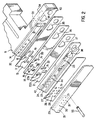
- Fig. 2 illustrates a multiple-jet ink jet head (in an exploded view), employing multiple ink jet devices in an array.
- the number and arrangement of the ink jet devices may vary, according to various embodiments of the invention.
- the device 10 shown in Fig. 1 is an air assisted solid ink jet device for ejecting ink droplets on-demand.
- preferred embodiments of the present invention employ gas, under pressure, to assist in the ejection of ink droplets.
- the pressurized gas provides a laminar air flow along the inner walls of the ink jet device for assisting the ejection of ink droplets through an ejection orifice.
- the gas is heated to affect the droplet and dot formation of hot melt ink ejected from the orifice.
- the temperature of the gas is adjustable to adjust the droplet and dot characteristics.
- the gas pressure or velocity is adjustable to adjust the ligament length, print gap and dot characteristics.
- ink jet devices are described with reference to ejecting droplets of ink for printing operations and, preferably, hot melt ink or solid ink (solid at room temperature).
- suitable materials such as thermoplastic compositions other than ink, adhesives, waxes, polymers or the like may be employed with ink jet apparatuses and methods according to further embodiments of the present invention.
- an air assisted solid ink jet apparatus 10 illustrated in Figs. 1 and 2 comprises a transducer housing 11, a first layered member 15 adjacent and preferably secured to the transducer housing 11, a second layered member 18 adjacent and preferably secured to the first layered member 15, a third layered member 21 adjacent and preferably secured to the second layered member 18, a fourth layered member 23 adjacent and preferably secured to the third layered member 21, a fifth layered member 26 adjacent and preferably secured to the fourth layered member 23, and a sixth layered member 29 adjacent and preferably secured to the fifth layered member 26.
- the transducer housing 11 comprises a transducer member 12a, ink passages 14, an ink inlet 33, an air inlet 34, and a first air passage 39, wherein the transducer member 12a includes a foot 13 coupled to a transducer 12.
- the transducer 12 expands and contracts in directions indicated by the arrow shown in Fig. 1, along the axis of elongation of the transducer 12.
- the transducer 12 is coupled to an ink chamber 24 through a foot 13 and the second layered member 18 which is made of a flexible diaphragm or membrane. Hot melt ink under pressure is delivered to the ink inlet 33, flows through various ink passageways and fills the ink chamber 24 within the ink jet apparatus 10.
- the elongation of the transducer 12 exerts pressure to the ink chamber 24, and the increased pressure in the ink chamber 24 causes ejection of droplets of ink through an ink orifice passageway 28.
- the action of a transducer on a flexible diaphragm to cause ink droplet ejection in itself is described in U.S. Patent No. 4,418,355 to DeYoung et al., incorporated herein by reference.
- ink droplets are assisted through an ink jet orifice 30 by pressurized air from the air chamber 31.
- the transducer housing 11 has a pair of ink passages 14 which are either machined or molded into a receiving surface 40, and through which hot melt ink from the ink inlet 33 is received.
- the ink passages are exposed but are abutted against the first layered member 15 during assembly.
- a transducer passage 32 is located between the pair of ink passages 14, wherein the ink passages 14 are symmetrically spaced from the transducer passage 32.
- the foot 13 coupled to the transducer 12, such as a piezoelectric or other suitable transducer, propagates through the transducer passage 32 as the length of the transducer 12 changes.
- the transducer passage 32 may have any suitable shape, preferably cylindrical, for easy sliding of the foot 13.
- a compressed air source (not shown) is connected to the air inlet 34 via a conduit (not shown) through which pressurized air is provided.
- the compressed air may be heated by either interposing an adjustable or regulatable heating source between the compressed air source and the ink jet apparatus, or by integrating the heating source into the transducer housing 11. Alternatively, the heating source may be installed within the compressed air source.
- a heater is typically located within or adjacent the head to maintain the ink in a liquid state for ejection.
- FIG. 1 is a diagrammatic representation of a typical head heater.
- the first layered member 15, which is placed and secured between the transducer housing 11 and the second layered member 18, comprises first channels 16, a second air passage 35, and apertures 17.
- the first layered member 15 is positioned against the receiving surface 40 of the transducer housing 11 thus forming tight seals around the ink passages 14 and the first air passage 39.
- the ink passages 14 are in fluid flow communication with the first channels 16 for free flow of hot melt ink.
- the second air passage 35 is substantially aligned with the first air passage 39 such that air flow can be freely communicated.
- the aperture 17 of the first layered member 15 serves as a passageway of the foot 13 that is coupled to the transducer 12. It is axially aligned with the transducer passage 32 along axis 50 for smooth movement of the foot 13 through the transducer passage 32.
- the aperture 17 shown in Fig. 2 is elliptically shaped and sufficiently large to negotiate at least two separate openings of the transducer passages 32.
- the elliptically shaped aperture 17 can be formed of any longitudinally suitable length to accommodate, for example, multiple transducer passages 32. To the same extent. the aperture 17 may be made smaller to accommodate only one transducer passage 32.
- the second layered member 18, which is placed and secured between the first layered member 15 and the third layered member 21, comprises second channels 19, flexible diaphragms 20, and the third air passage 36.
- the second layered member 18 creates tight seals around the first channels 16 and the second air passage 35.
- the apertures 17 are closed by the second layered member 21 made with any suitable flexible materials, such as stainless steel or plastic, thereby forming a flexible diaphragm or membrane.
- the transducer 12, together with the second layered member 18 comprises one form of a pressure pulse generating actuator.
- the pressure created by the transducer 12 and the second layered member 18 arrangement is transmitted through the ink chamber 24. This causes the ejection of ink droplets from an ink orifice passageway 28.
- the second channels 19 are in fluid flow communication with the corresponding first channels 16 in the first layered member 15.
- the third air passage 36 is in airflow communication with the second air passage 35.
- the second layered member 18 has second channels 19 which, in preferred embodiments, includes screens 42 to filter out any unwanted debris or particles contained in hot melt ink.
- the third layered member 21, which is placed and secured between the second layered member 18 and the fourth layered member 23, comprises ink conduits 22 and a fourth air passage 37, wherein the ink conduits 22 are in fluid flow communication with the second channels 19 and the fourth air passage 37 is in air flow communication with the third air passage 36.
- the third layered member 21 forms tight seals around the second channels 19 and the third air passage 36 to prevent any loss of ink and air pressure respectively.
- the fourth layered member 23, which is placed and secured between the third layered member 21 and the fifth layered member 26, comprises a pair of air passages 25 and ink chambers 24, wherein each ink chamber has a base 43 and an ink outlet 44.
- the base 43 is in fluid flow communication with the supplying end 22b of the third layered member 21.
- the ink chamber 24 depicted in Figs. 1 and 2 is frustoconically shaped.
- the ink chamber 24 may be cylindrical or of other suitable shapes.
- the thickness of the fourth layered member 23 may be varied during fabrication of that member to control the volume of the ink chamber 24.
- Each ink chamber 24 is located between the pair of air passages 25, wherein the air passages 25 are symmetrically spaced from the ink chamber 24.
- the air passages 25 are in air flow communication with the air receiving passage 38 which in turn is in air flow communication with the fourth air passage 37.
- the fourth layered member 23 forms a tight seal around the fourth air passage 37 to prevent any loss of air pressure.
- both air passages 25 depicted in Fig. 1 have the same shape and volume.
- the symmetry allows even air pressure in the air chamber 31 and in outwardly ejected air through an ink jet orifice 30.
- the fifth layered member 26, which is placed and secured between the fourth layered member 23 and the sixth layered member 29, comprises ink orifice passageways 28 and air conduits 27.
- the air conduits 27 are symmetrically situated from the ink orifice passageway 28.
- a pair of air conduits 27 that are in air flow communication with the air passages 25 are provided.
- the fifth layered member 26 provides tight seals around the air passages 25 to maintain a pneumatic condition.
- the ink orifice passageway 28 is axially aligned with the ink outlet 44 of the ink chamber 24, as indicated by axis 50 in Fig. 1. For each ink chamber 24, there is a corresponding ink orifice passageway 28 in the fifth layered member 26.
- the ink orifice passageway 28 is of smaller diameter than the ink outlet 44 of the ink chamber 24 to prevent undemanded flow of hot melt ink through the opening.
- the fifth layer member 26 forms tight seals around the ink chambers 24 to prevent ink leakage.
- the sixth layered member 29 comprises ink jet orifices 30, air chamber wall 51, and an air chamber 31.
- the fifth layered member 26 is secured to the air chamber wall 51 of the air chamber 31 to form an air tight seal.
- the air chamber 31 is symmetrically aligned along the axis 50 so that it is in air flow communication with the air passages 25 through the air conduits 27.
- the ink jet orifices 30 may be of any suitable shape, such as cylindrical or frustoconical shape.
- the thickness of the air chamber wall 51 dictates the volume of the air chamber.
- the ink jet orifices 30 are also axially aligned with the corresponding ink orifice passageways 28, as indicated by the axis 50.
- the opening size of the ink jet orifices 30 is greater than the ink orifice passageway 28.
- the opening should be small enough to maintain sufficient air pressure to accelerate ink droplets through the ink jet orifice 30.
- Pressurized air is delivered to the air inlet 34 of the air assisted solid ink jet apparatus 10. Air passes through the various layered members and flows into the air chamber 31. As air approaches the center of the head, it changes direction and flows outwardly through the ink jet orifices 30. This air flow accelerates at least the ligament portions of ink droplets generated at the ink orifice passageways 28 in response to pressure pulses generated by the foot 13 coupled to the transducer 12. As described in more detail below, the resulting air flow assists in controlling the ink droplets as they are ejected outwardly from the ink orifice passageways 28. As a result, more uniform and symmetric ink drops with controlled ligament lengths may be generated by the ink jet apparatus 10. These drops travel through the ink jet orifice 30 and toward the printing media.
- the bonding or securing of the above mentioned layered members may be achieved by attaching each layered member against an adjacent layered member using an adhesive or other suitable bonding materials or securing means.
- Alignment dowels 55 may be used to align the respective layers during bonding or securing steps.
- the above-noted layered members are formed as a unitary structure, e.g., from a single sheet of material, such as metal, which is cut and drilled to the configuration shown in Fig. 2.
- the each layered member and transducer housing may be formed by suitable processes, such as molding or extruding from a metal, plastic or other resin-type material.
- FIG. 3 Another possible embodiment, shown in Fig. 3, has a plurality of ink passages 61 fabricated into the fourth layered member 23, rather than having them in the transducer housing 11.
- the first layered member 15 may be eliminated, for first channels 16 are no longer needed. Consequently, the ink passages 61 of the third layered member 21 are in fluid flow communication with the ink inlet 33 to receive hot melt ink.
- the ink passages 61 are also in fluid flow communication with the ink chamber 24.
- FIG. 4 illustrates the ink jet apparatus without the first layered member 15, thus rendering the manufacturing process simpler.
- the second layered member 18, which is made of a flexible diaphragm or membrane is placed directly against the transducer housing 11.
- the air passages 25, which are shown in the fourth layered member 23 of Fig. 1 are omitted from that member, and instead, provided in the sixth layered member 29, eliminating the air conduits 27 from the fifth layered member 26.
- the ink jet orifice 30 may be cylindrically tapered and aligned along the axis 50 to increase the air velocity at the output.
- the above described embodiments of the present invention have many advantages, including the ease of manufacture and repair.
- the preferred embodiments have a layered configuration, wherein the ink jet apparatus may be made by attaching different layered members. This minimizes manufacturing difficulties and expenses by eliminating the need for expensive cast parts. Also, because of this feature, any array of ink jet head may be manufactured.
- the rectangular column aligned along the jetting array is particularly applicable to multi-hole orifice configurations used in industrial applications where large dot size is required.
- the ink passages 14 are arranged in the transducer housing 11. This arrangement provides various benefits, including the availability of a larger volume of ink. Also, when using hot melt ink, it is preferred that a heating source be provided to prevent ink in the ink passages and chambers from hardening during operation.
- the heating source such as a resistive heater, may be part of the ink jet apparatus, and are typically mounted to or in the transducer housing structure.
- the location of the ink passages 14 directly within the transducer housing allows the heat source to efficiently communicate heat through a single body (the transducer housing structure) to the ink in the ink passages 14.
- the ink passages where located in other layers the heat from a heater mounted to the transducer housing would have to communicate through one or more layers and layer transitions, which can act as heat insulators and dissipaters.
- the location of the ink passages 14 in the transducer housing also provides improvements with respect to the gas assist feature.
- the fourth layered member 23 may be made relatively thin, thus minimizing the overall width of the ink jet head.
- the ability to minimize the overall width of the ink jet head is particularly beneficial with the gas assist feature, as a means to offset at least some of the additional width provided by the additional layer or layers and a gas chamber employed with the gas assist feature.
- the pressurized gas prevents debris particles from falling and/or accumulating on the ink jet orifices 30 and tends to "blow" out excess ink or debris accumulations from the ink jet orifices, thereby making jetting more reliable.
- Still another advantage of the above embodiments is that by forming a high speed laminar flow at the exit of the ink jet orifice 30, ink ligaments or droplets can be uniformly accelerated toward the printing media. Additionally, the droplets of smaller size or satellite drops are accelerated at a higher speed due to their size and land on the printing media substantially at the same time and region, thus improving the resolution. Moreover, the high speed laminar flow reduces friction at the ink jet orifice 30, thus reducing the deformation of ink droplets as they are ejected from the orifice.
- an air valve mechanism is interposed between a compressed air source and an ink jet head for adjusting air pressure provided to the air inlet 34.
- ligaments formed on a viscous and/or hot melt ink droplet typically travel at a slower velocity than the head of the droplets.
- the droplet head may travel at about 13 meters/second, while the ligament tail may travel at about 7 meters/second.
- the gas (or air) velocity is adjusted or selected to be greater than the ligament tail velocity, but less than the ligament head velocity, such that velocity of the column of air acts on the ligament tail (to accelerate the tail) but has little or no effect on the droplet head.
- the air velocity is adjusted to minimize and/or otherwise control the ligament length.
- the pressurized air is heated by an adjustable or regulatable heating source and/or by a heating source incorporated in the ink jet head, to produce a column of heated air through each ink jet orifice.
- the column of heated air provides low heat loss of the droplet in flight, when hot melt ink is used, and local heating of the printing substrate, thereby giving an additional level of control to the print quality and resolution.
- Substrate heating for the control of dot formation has previously been provided by, for example, heated platens arranged behind the printing substrate.
- the precise location on the printing substrate at which an ejected ink droplet lands can be temperature controlled by the control of the column of heated air which accompanies the ejected droplet.
- the column of air is preferably adjusted to impinge on the same surface at about the same location and nearly the same time as the ejected droplet of ink. This can provide a distinct improvement over processes of pre-heating a substrate prior to printing or heating of the substrate from the surface opposite to the printing surface, wherein imprecise dissipation and conduction of heat through the substrate provide imprecise temperature control.
Landscapes
- Engineering & Computer Science (AREA)
- Manufacturing & Machinery (AREA)
- Particle Formation And Scattering Control In Inkjet Printers (AREA)
Abstract
Description
- This invention relates to ink jet apparatuses and methods for ink jet printers, and in particular embodiments, to an air assisted drop on demand ink jet apparatus for jetting a phase change medium, such as solid ink.
- Preferred embodiments of the present invention relate to a gas assisted ink jet apparatus for ejecting droplets of a liquid phase medium, such as ink, with the assistance of pressurized, heated gas, such as air, onto paper or other substrate to generate images, text, or other patterns.
- Typical drop-on-demand ink jet apparatuses operate to eject ink droplets from an ink jet head by selective actuations of one or more transducers within the ink jet head. For example, U.S. Patent No. 4,418,355 to DeYoung et al. describes an ink jet head having several jets, each jet having a piezoelectric transducer in pressure communication with an ink chamber which is in liquid flow communication with a small jet opening. Ink droplets are formed from ink in the ink chambers and are ejected through the small jet openings in the ink jet head by selective actuations of the piezoelectric transducers. The ejected ink droplets travel at a relatively high velocity, across a gap from the ink jet head to a printing substrate.
- Some ink jet printing apparatuses have been designed to operate with phase change or solid ink -- inks that are heated to melt or transition from a solid phase to a liquid phase prior to ejection. Such printing apparatuses typically employ a heating mechanism, such as a resistive heater, in the ink jet head to melt or maintain the ink in a liquid state for ejection.
- Ink jet printing, particularly phase change or solid ink jet printing, can place great demands on the ink jet printing apparatus. In typical printing environments, paper dust and debris tends to accumulate on the surface of the opening where ink droplets are ejected. This often causes jets to deprime (resulting in missing jets) during or following the operation of a printer. Introduction of debris into the ink chamber when the apparatus is in a stand-by mode is another, more permanent, cause of failure of ink jet printers. When the ink jet head cools down, through the phase transition of the hot melt ink, ink shrinkage tends to pull surface debris into the jet openings and can be difficult, if not impossible, to remove once it is internally incorporated. In particular industrial applications, such as printing on fabric or corrugated boxes, printing equipment is required to operate in relatively dusty and dirty factory environments. Lack of reliability in these environments has limited the acceptance of ink jet printing in these applications.
- Another problem that tends to affect drop on demand ink jet printers, especially those designed to operate with relatively high viscosity mediums and/or hot melt or solid mediums, is the formation of ligaments on and around ejected droplets. Ligaments can result in poor dot formation and poor print quality. Because many suitable ink materials have surface tensions typically of 29+/-2 dyne/centimeters, the ligament length cannot be reduced beyond certain limits by modification of the surface tension of the ink composition.
- The ligament phenomenon typically results in a ligament head velocity of about 13 meters/second and a tail velocity of about 7 meters/second. As a result, a ligamented droplet in flight elongates as it travels further from the jetting device. Practically, this sets a limit on the print gap (the distance between the ink jet head and the printing surface or substrate) and the relative translational speed between the print head and the printing surface. For example, with a print gap of 1 millimeter (0.04") and translational speed of 25 inches per second, the difference in arrival time of the head and tail is approximately 200 micro-seconds, which corresponds to 0.005". Since high resolution printing typically requires dot sizes of less than 0.005", any increase in print gap or traverse speed results in unacceptable dot size or shape. Although ink jet heads are capable of higher frequency operation, the ligament length control tends to limit the useable frequency to approximately 7.5 KHz at 300 dots per inch. However, industrial applications and high duty cycle environments, such as spot color on 310 ppm continuous forms printers, require larger printing gaps, higher frequency and high reliability.
- Another concern often associated with solid ink jet printing is in the control of dot size on the print media. Typically, this is accomplished by control of the temperature of jetted ink and print media temperature. These conditions dictate the solidification time of the solid ink droplet on the print media and thereby control the drop spread, dot size and penetration into the print media.
- One trend has been to employ compressed air to accelerate droplets of ejected ink, such as illustrated in U.S. Patent No. 4,106,032 of Miura et al. The Miura patent describes a two compartment ink chamber ink jet head which comprises an inner and an outer ink compartments which communicate with one another through a connecting conduit, and an air source for facilitating the ejection of ink droplets emitted from the outer ink chamber. However, there are a number of drawbacks associated with this apparatus. For example, it can be difficult to align the connecting passageways, internal ink orifice outlet, and main external orifice outlet. Also, because of the internal passageways' location and size, they are difficult to clean when the passageways are clogged with contaminants. Another form of air-assisted ink jet head is illustrated in U.S. Patent No. 4,728,969 of Le et al. It describes an air-assisted drop-on-demand ink jet head with a single compartment ink chamber.
- EP-A-0252676 of Tektronix, Inc. describes an air-assisted ink jet apparatus that uses pressurized air to improve the droplet quality. The ink jet head has a single compartment ink chamber in communication with an inlet passageway, and an orifice passageway and outlet. A diaphragm transmits a pressure wave through the ink chamber causing the ejection of ink droplets, and pressurized air is supplied to the ink jet head to accelerate the ink droplets, assisting in carrying them outwardly from the ink jet head.
- A gas assisted ink jet apparatus according to the present invention includes, or is operable with, a compressed air source and is suitable for use in ink jet printers. The apparatus is for selectively ejecting liquid droplets each having a droplet head travelling at a first velocity and a droplet ligament travelling at a second velocity on ejection, the first velocity being greater than the second velocity and comprises:
- a transducer housing;
- a diaphragm member;
- at least one transducer member disposed within the transducer housing in pressure communication with the diaphragm member for selectively exerting a pressure on the diaphragm member;
- a chamber member defining a chamber for containing a volume of jettable liquid and a liquid outlet, wherein the chamber is provided in pressure communication with the transducer member, through the diaphragm member, so the pressure selectively exerted by the transducer member is transferred to the chamber via the diaphragm member causing selective ejection of liquid droplets through the outlet;
- an air chamber portion having an air chamber and an orifice, wherein the air
chamber is in air flow communication with the compressed air source, and the orifice
is in alignment with the outlet to allow an air flow through the orifice with the
ejection of liquid droplets; characterized by:
- means for setting the velocity of the air flow through the orifice to a third velocity greater than the second velocity and less than the first velocity.
-
- The air chamber is adapted to produce a laminar air flow through the orifice. As a result, the air chamber provides outwardly directed air stream through the orifice which assists in the ejection of ink droplets from the liquid chamber outlet and through the air chamber orifice. The air stream provides a laminar flow which assists the ejection of ink droplets and controls ligament lengths on the droplets. The air flow also provides a cleaning effect for removing accumulations of ink at or near the ink ejection orifice.
- In preferred embodiments, the air is heated, either with a heater associated with the compressed air source, a heater disposed between the compressed air source and the inkjet head and/or a heater located within or mounted to the ink jet head. The heated air affects the drop and dot formation of hot melt mediums and preferably, the heat source is adjustable to adjust the drop and dot forming characteristics of the ink jet apparatus.
- In accordance with a further preferred embodiment of the present invention, the transducer member may comprise a piezoelectric transducer coupled to a foot for producing pressure pulses against the diaphragm member. The diameter of the orifice is preferably greater than that of the outlet, however, small enough to maintain sufficient air pressure to accelerate liquid droplets through the orifice.
- Preferably, the diaphragm member further comprises a channel equipped with a screen suitable for removing contaminants.
- Preferably, the orifice is in alignment with an orifice passageway having a smaller diameter than the outlet to prevent undemanded flow of liquid through the opening of the orifice passageway.
- The present invention further provides a method of selectively ejecting liquid droplets having a droplet head travelling at a first velocity and a droplet ligament travelling at a second velocity upon ejection, the first velocity being greater than the second velocity, the method comprising:
- containing a volume of jettable liquid in a chamber member;
- selectively applying pressure to a diaphragm in pressure communication with the chamber to transmit droplets of the liquid from the chamber to an air chamber through an outlet;
- ejecting the droplets from the air chamber through an orifice; characterized by maintaining a velocity of the air flow through the orifice at a third velocity greater than the second velocity and less than the first velocity.
-
-
- Fig. 1 is a cross sectional view of a gas assisted liquid jet apparatus according to an embodiment of the invention.
- Fig. 2 is an exploded view of a gas assisted liquid jet apparatus according to an embodiment of the invention.
- Fig. 3 is a cross sectional view of another embodiment of a gas assisted liquid jet apparatus.
- Fig. 4 is a cross sectional view of a further embodiment of a gas assisted liquid jet apparatus.
- Fig. 5 is a cross sectional view of yet another embodiment of a gas assisted liquid jet apparatus.
-
- Fig. 1 illustrates a sectional view of a single ink jet device of a multiple-jet ink jet head. Fig. 2 illustrates a multiple-jet ink jet head (in an exploded view), employing multiple ink jet devices in an array. The number and arrangement of the ink jet devices may vary, according to various embodiments of the invention.
- The
device 10 shown in Fig. 1 is an air assisted solid ink jet device for ejecting ink droplets on-demand. As described in further detail below, preferred embodiments of the present invention employ gas, under pressure, to assist in the ejection of ink droplets. The pressurized gas provides a laminar air flow along the inner walls of the ink jet device for assisting the ejection of ink droplets through an ejection orifice. Preferably, the gas is heated to affect the droplet and dot formation of hot melt ink ejected from the orifice. Also, in preferred embodiments, the temperature of the gas is adjustable to adjust the droplet and dot characteristics. In further preferred embodiments, the gas pressure or velocity is adjustable to adjust the ligament length, print gap and dot characteristics. - For purposes of this application, ink jet devices are described with reference to ejecting droplets of ink for printing operations and, preferably, hot melt ink or solid ink (solid at room temperature). However, it will be understood that other suitable materials, such as thermoplastic compositions other than ink, adhesives, waxes, polymers or the like may be employed with ink jet apparatuses and methods according to further embodiments of the present invention.
- The illustrated embodiment is particularly well suited for a layered ink jet head design, wherein the head is formed of layers or laminates. Such layered designs can significantly reduce the manufacturing costs and simplify the manufacturing process. For example, an air assisted solid
ink jet apparatus 10 illustrated in Figs. 1 and 2 comprises atransducer housing 11, a firstlayered member 15 adjacent and preferably secured to thetransducer housing 11, a secondlayered member 18 adjacent and preferably secured to the firstlayered member 15, a thirdlayered member 21 adjacent and preferably secured to the secondlayered member 18, a fourthlayered member 23 adjacent and preferably secured to the thirdlayered member 21, a fifthlayered member 26 adjacent and preferably secured to the fourthlayered member 23, and a sixthlayered member 29 adjacent and preferably secured to the fifthlayered member 26. - In the embodiment illustrated in Figs. 1 and 2, the
transducer housing 11 comprises a transducer member 12a,ink passages 14, anink inlet 33, anair inlet 34, and afirst air passage 39, wherein the transducer member 12a includes afoot 13 coupled to atransducer 12. Thetransducer 12 expands and contracts in directions indicated by the arrow shown in Fig. 1, along the axis of elongation of thetransducer 12. Thetransducer 12 is coupled to anink chamber 24 through afoot 13 and the secondlayered member 18 which is made of a flexible diaphragm or membrane. Hot melt ink under pressure is delivered to theink inlet 33, flows through various ink passageways and fills theink chamber 24 within theink jet apparatus 10. The elongation of thetransducer 12 exerts pressure to theink chamber 24, and the increased pressure in theink chamber 24 causes ejection of droplets of ink through anink orifice passageway 28. The action of a transducer on a flexible diaphragm to cause ink droplet ejection in itself is described in U.S. Patent No. 4,418,355 to DeYoung et al., incorporated herein by reference. However, according to embodiments of the present invention, ink droplets are assisted through anink jet orifice 30 by pressurized air from theair chamber 31. - The
transducer housing 11 has a pair ofink passages 14 which are either machined or molded into a receivingsurface 40, and through which hot melt ink from theink inlet 33 is received. The ink passages are exposed but are abutted against the firstlayered member 15 during assembly. Atransducer passage 32 is located between the pair ofink passages 14, wherein theink passages 14 are symmetrically spaced from thetransducer passage 32. Thefoot 13 coupled to thetransducer 12, such as a piezoelectric or other suitable transducer, propagates through thetransducer passage 32 as the length of thetransducer 12 changes. Thetransducer passage 32 may have any suitable shape, preferably cylindrical, for easy sliding of thefoot 13. - The
first air passage 39 of thetransducer housing 11, which provides a direct path from theair inlet 34 to asecond air inlet 35 of the secondlayered member 15, is in air flow communication with theair inlet 34. A compressed air source (not shown) is connected to theair inlet 34 via a conduit (not shown) through which pressurized air is provided. The compressed air may be heated by either interposing an adjustable or regulatable heating source between the compressed air source and the ink jet apparatus, or by integrating the heating source into thetransducer housing 11. Alternatively, the heating source may be installed within the compressed air source. For ink jet head designs for hot melt inks, a heater is typically located within or adjacent the head to maintain the ink in a liquid state for ejection. Further preferred embodiments of the invention employ such head heaters to heat the compressed air as the air passes through the head. Pressure of the air may be adjustable or regulatable by interposing a pressure adjustment valve between the compressed air source and theair inlet 34. Also, the temperature of the air may be adjusted by providing suitable heat adjustment mechanisms on or with the heater. - The first
layered member 15, which is placed and secured between thetransducer housing 11 and the secondlayered member 18, comprisesfirst channels 16, asecond air passage 35, andapertures 17. The firstlayered member 15 is positioned against the receivingsurface 40 of thetransducer housing 11 thus forming tight seals around theink passages 14 and thefirst air passage 39. However, theink passages 14 are in fluid flow communication with thefirst channels 16 for free flow of hot melt ink. Similarly, thesecond air passage 35 is substantially aligned with thefirst air passage 39 such that air flow can be freely communicated. - The
aperture 17 of the firstlayered member 15 serves as a passageway of thefoot 13 that is coupled to thetransducer 12. It is axially aligned with thetransducer passage 32 alongaxis 50 for smooth movement of thefoot 13 through thetransducer passage 32. Theaperture 17 shown in Fig. 2 is elliptically shaped and sufficiently large to negotiate at least two separate openings of thetransducer passages 32. In general, the elliptically shapedaperture 17 can be formed of any longitudinally suitable length to accommodate, for example,multiple transducer passages 32. To the same extent. theaperture 17 may be made smaller to accommodate only onetransducer passage 32. - The second
layered member 18, which is placed and secured between the firstlayered member 15 and the thirdlayered member 21, comprisessecond channels 19,flexible diaphragms 20, and thethird air passage 36. The secondlayered member 18 creates tight seals around thefirst channels 16 and thesecond air passage 35. Theapertures 17 are closed by the secondlayered member 21 made with any suitable flexible materials, such as stainless steel or plastic, thereby forming a flexible diaphragm or membrane. Thetransducer 12, together with the secondlayered member 18 comprises one form of a pressure pulse generating actuator. The pressure created by thetransducer 12 and the secondlayered member 18 arrangement is transmitted through theink chamber 24. This causes the ejection of ink droplets from anink orifice passageway 28. - As shown in Fig. 2, the
second channels 19 are in fluid flow communication with the correspondingfirst channels 16 in the firstlayered member 15. Similarly, thethird air passage 36 is in airflow communication with thesecond air passage 35. - The second
layered member 18 hassecond channels 19 which, in preferred embodiments, includesscreens 42 to filter out any unwanted debris or particles contained in hot melt ink. - The third
layered member 21, which is placed and secured between the secondlayered member 18 and the fourthlayered member 23, comprisesink conduits 22 and afourth air passage 37, wherein theink conduits 22 are in fluid flow communication with thesecond channels 19 and thefourth air passage 37 is in air flow communication with thethird air passage 36. When secured to the secondlayered member 18, the thirdlayered member 21 forms tight seals around thesecond channels 19 and thethird air passage 36 to prevent any loss of ink and air pressure respectively. Theink conduit 22, which may be shaped in any manner sufficient to receive hot melt ink from thesecond channel 19 and to convey it to theink chamber 24, comprises a receiving end 22a and a supplyingend 22b. In the preferred embodiment of Fig. 1, in order to create tight seals, the receiving end 22a of theink conduit 22 has the same shape as that of thesecond channel 19, and the supplyingend 22b has the same shape as that of thebase 43 of theink chamber 24. - The fourth
layered member 23, which is placed and secured between the thirdlayered member 21 and the fifthlayered member 26, comprises a pair ofair passages 25 andink chambers 24, wherein each ink chamber has abase 43 and anink outlet 44. Thebase 43 is in fluid flow communication with the supplyingend 22b of the thirdlayered member 21. In general, theink chamber 24 depicted in Figs. 1 and 2 is frustoconically shaped. However, theink chamber 24 may be cylindrical or of other suitable shapes. The thickness of the fourthlayered member 23 may be varied during fabrication of that member to control the volume of theink chamber 24. - Each
ink chamber 24 is located between the pair ofair passages 25, wherein theair passages 25 are symmetrically spaced from theink chamber 24. Theair passages 25 are in air flow communication with theair receiving passage 38 which in turn is in air flow communication with thefourth air passage 37. The fourthlayered member 23 forms a tight seal around thefourth air passage 37 to prevent any loss of air pressure. - Preferably, both
air passages 25 depicted in Fig. 1 have the same shape and volume. The symmetry allows even air pressure in theair chamber 31 and in outwardly ejected air through anink jet orifice 30. - The fifth
layered member 26, which is placed and secured between the fourthlayered member 23 and the sixthlayered member 29, comprises ink orifice passageways 28 andair conduits 27. Theair conduits 27 are symmetrically situated from theink orifice passageway 28. For eachink orifice passageway 28, a pair ofair conduits 27 that are in air flow communication with theair passages 25 are provided. Other than the openings provided by theair conduits 27, the fifthlayered member 26 provides tight seals around theair passages 25 to maintain a pneumatic condition. - The
ink orifice passageway 28 is axially aligned with theink outlet 44 of theink chamber 24, as indicated byaxis 50 in Fig. 1. For eachink chamber 24, there is a correspondingink orifice passageway 28 in the fifthlayered member 26. Theink orifice passageway 28 is of smaller diameter than theink outlet 44 of theink chamber 24 to prevent undemanded flow of hot melt ink through the opening. Other than the openings of ink orifice passageways 28, thefifth layer member 26 forms tight seals around theink chambers 24 to prevent ink leakage. - The sixth
layered member 29 comprisesink jet orifices 30,air chamber wall 51, and anair chamber 31. The fifthlayered member 26 is secured to theair chamber wall 51 of theair chamber 31 to form an air tight seal. Theair chamber 31 is symmetrically aligned along theaxis 50 so that it is in air flow communication with theair passages 25 through theair conduits 27. Theink jet orifices 30 may be of any suitable shape, such as cylindrical or frustoconical shape. The thickness of theair chamber wall 51 dictates the volume of the air chamber. - The
ink jet orifices 30 are also axially aligned with the corresponding ink orifice passageways 28, as indicated by theaxis 50. Preferably, the opening size of theink jet orifices 30 is greater than theink orifice passageway 28. However, the opening should be small enough to maintain sufficient air pressure to accelerate ink droplets through theink jet orifice 30. - Pressurized air is delivered to the
air inlet 34 of the air assisted solidink jet apparatus 10. Air passes through the various layered members and flows into theair chamber 31. As air approaches the center of the head, it changes direction and flows outwardly through theink jet orifices 30. This air flow accelerates at least the ligament portions of ink droplets generated at the ink orifice passageways 28 in response to pressure pulses generated by thefoot 13 coupled to thetransducer 12. As described in more detail below, the resulting air flow assists in controlling the ink droplets as they are ejected outwardly from the ink orifice passageways 28. As a result, more uniform and symmetric ink drops with controlled ligament lengths may be generated by theink jet apparatus 10. These drops travel through theink jet orifice 30 and toward the printing media. - The bonding or securing of the above mentioned layered members may be achieved by attaching each layered member against an adjacent layered member using an adhesive or other suitable bonding materials or securing means. Alignment dowels 55 may be used to align the respective layers during bonding or securing steps.
- In the illustrated embodiment, the above-noted layered members are formed as a unitary structure, e.g., from a single sheet of material, such as metal, which is cut and drilled to the configuration shown in Fig. 2. However, it will be readily recognized that the each layered member and transducer housing may be formed by suitable processes, such as molding or extruding from a metal, plastic or other resin-type material.
- Another possible embodiment, shown in Fig. 3, has a plurality of ink passages 61 fabricated into the fourth
layered member 23, rather than having them in thetransducer housing 11. In this embodiment, the firstlayered member 15 may be eliminated, forfirst channels 16 are no longer needed. Consequently, the ink passages 61 of the thirdlayered member 21 are in fluid flow communication with theink inlet 33 to receive hot melt ink. The ink passages 61 are also in fluid flow communication with theink chamber 24. - Another embodiment shown in Fig. 4 illustrates the ink jet apparatus without the first
layered member 15, thus rendering the manufacturing process simpler. As a result, the secondlayered member 18, which is made of a flexible diaphragm or membrane is placed directly against thetransducer housing 11. In addition, theair passages 25, which are shown in the fourthlayered member 23 of Fig. 1, are omitted from that member, and instead, provided in the sixthlayered member 29, eliminating theair conduits 27 from the fifthlayered member 26. As a result, in lieu of the fifthlayered member 26 withair conduits 27 as shown in Fig. 1, a different embodiment of the fifthlayered member 53 with no air conduits is needed. In addition, theink jet orifice 30 may be cylindrically tapered and aligned along theaxis 50 to increase the air velocity at the output. - The above described embodiments of the present invention have many advantages, including the ease of manufacture and repair. As illustrated and described above, the preferred embodiments have a layered configuration, wherein the ink jet apparatus may be made by attaching different layered members. This minimizes manufacturing difficulties and expenses by eliminating the need for expensive cast parts. Also, because of this feature, any array of ink jet head may be manufactured. The rectangular column aligned along the jetting array is particularly applicable to multi-hole orifice configurations used in industrial applications where large dot size is required.
- In preferred embodiments discussed above, the
ink passages 14 are arranged in thetransducer housing 11. This arrangement provides various benefits, including the availability of a larger volume of ink. Also, when using hot melt ink, it is preferred that a heating source be provided to prevent ink in the ink passages and chambers from hardening during operation. The heating source, such as a resistive heater, may be part of the ink jet apparatus, and are typically mounted to or in the transducer housing structure. Thus, the location of theink passages 14 directly within the transducer housing allows the heat source to efficiently communicate heat through a single body (the transducer housing structure) to the ink in theink passages 14. In contrast, if the ink passages where located in other layers, the heat from a heater mounted to the transducer housing would have to communicate through one or more layers and layer transitions, which can act as heat insulators and dissipaters. - The location of the
ink passages 14 in the transducer housing also provides improvements with respect to the gas assist feature. With theink passages 14 located in the transducer housing, rather than the fourthlayered member 23 or other layer, the fourthlayered member 23 may be made relatively thin, thus minimizing the overall width of the ink jet head. The ability to minimize the overall width of the ink jet head is particularly beneficial with the gas assist feature, as a means to offset at least some of the additional width provided by the additional layer or layers and a gas chamber employed with the gas assist feature. - The pressurized gas (or air) prevents debris particles from falling and/or accumulating on the
ink jet orifices 30 and tends to "blow" out excess ink or debris accumulations from the ink jet orifices, thereby making jetting more reliable. Still another advantage of the above embodiments is that by forming a high speed laminar flow at the exit of theink jet orifice 30, ink ligaments or droplets can be uniformly accelerated toward the printing media. Additionally, the droplets of smaller size or satellite drops are accelerated at a higher speed due to their size and land on the printing media substantially at the same time and region, thus improving the resolution. Moreover, the high speed laminar flow reduces friction at theink jet orifice 30, thus reducing the deformation of ink droplets as they are ejected from the orifice. - Another advantage is that the air velocity may be adjusted to increase the droplet velocity. In preferred embodiments, an air valve mechanism is interposed between a compressed air source and an ink jet head for adjusting air pressure provided to the
air inlet 34. This allows the ink jet apparatus to be adjustable to accommodate various printing gaps and jetting frequencies and allows larger printing gaps and/or higher jetting frequencies with improved drop formation and shape. As noted above, ligaments formed on a viscous and/or hot melt ink droplet typically travel at a slower velocity than the head of the droplets. For example, the droplet head may travel at about 13 meters/second, while the ligament tail may travel at about 7 meters/second. In preferred embodiments, the gas (or air) velocity is adjusted or selected to be greater than the ligament tail velocity, but less than the ligament head velocity, such that velocity of the column of air acts on the ligament tail (to accelerate the tail) but has little or no effect on the droplet head. As a result, the air velocity is adjusted to minimize and/or otherwise control the ligament length. - In further preferred embodiments, the pressurized air is heated by an adjustable or regulatable heating source and/or by a heating source incorporated in the ink jet head, to produce a column of heated air through each ink jet orifice. The column of heated air provides low heat loss of the droplet in flight, when hot melt ink is used, and local heating of the printing substrate, thereby giving an additional level of control to the print quality and resolution. Substrate heating for the control of dot formation has previously been provided by, for example, heated platens arranged behind the printing substrate. However, according to preferred embodiments of the present invention, the precise location on the printing substrate at which an ejected ink droplet lands can be temperature controlled by the control of the column of heated air which accompanies the ejected droplet. The column of air is preferably adjusted to impinge on the same surface at about the same location and nearly the same time as the ejected droplet of ink. This can provide a distinct improvement over processes of pre-heating a substrate prior to printing or heating of the substrate from the surface opposite to the printing surface, wherein imprecise dissipation and conduction of heat through the substrate provide imprecise temperature control.
Claims (9)
- A gas assisted liquid jet apparatus operable with a compressed air source for selectively ejecting liquid droplets each having a droplet head travelling at a first velocity and a droplet ligament travelling at a second velocity upon ejection, the first velocity being greater than the second velocity, the liquid jet apparatus comprising:a transducer housing (11);a diaphragm member (18,20);at least one transducer member (12a) disposed within the transducer housing (11) in pressure communication with the diaphragm member (18,20) for selectively exerting a pressure on the diaphragm member (18,20);a chamber member (23) defining a chamber (24) for containing a volume of jettable liquid and a liquid outlet (28), wherein the chamber (24) is provided in pressure communication with the transducer member (12a), through the diaphragm member (18,20), so the pressure selectively exerted by the transducer member (12a) is transferred to the chamber (24) via the diaphragm member (20) causing selective ejection of liquid droplets through the outlet (28);an air chamber portion (29) having an air chamber (31) and an orifice (30), wherein the air chamber (31) is in air flow communication with the compressed air source, and the orifice (30) is in alignment with the outlet (28) to allow an air flow through the orifice (30) with the ejection of liquid droplets; characterized by:means for setting the velocity of the air flow through the orifice to a third velocity greater than the second velocity and less than the first velocity.
- The apparatus of claim 1, further including means for heating air received within the air chamber.
- The apparatus of claim 1 or 2, in which the transducer member (12a) comprises a piezoelectric transducer (12) coupled to a foot (13) for producing pressure pulses against the diaphragm member (18,20).
- The apparatus of any of claims 1 to 3, in which the diameter of the orifice (30) is greater than that of the outlet (28), however, small enough to maintain sufficient air pressure to accelerate liquid droplets through the orifice (30).
- The apparatus of any preceding claim, wherein the diaphragm member (18,20) further comprises a channel (19) equipped with a screen (42) suitable for removing contaminants.
- The apparatus of any preceding claim, wherein the orifice (30) is in alignment with an orifice passageway (28) having a smaller diameter than the outlet to prevent undemanded flow of liquid through the opening of the orifice passageway.
- A method of selectively ejecting liquid droplets having a droplet head travelling at a first velocity and a droplet ligament travelling at a second velocity upon ejection, the first velocity being greater than the second velocity, the method comprising:characterized by maintaining a velocity of the air flow through the orifice (30) at a third velocity greater than the second velocity and less than the first velocity.containing a volume of jettable liquid in a chamber member (23);selectively applying pressure to a diaphragm (20) in pressure communication with the chamber (23) to transmit droplets of the liquid from the chamber (23) to an air chamber (31) through an outlet (28);ejecting the droplets from the air chamber (31) through an orifice (3);
- The method of claim 7, the method further including heating air received within the air chamber (31).
- The method of claim 7 or 8, wherein the step of maintaining the velocity of the air flow through the orifice (30) further includes coupling a compressed air source to the air chamber.
Applications Claiming Priority (3)
| Application Number | Priority Date | Filing Date | Title |
|---|---|---|---|
| US08/608,551 US5798774A (en) | 1996-02-28 | 1996-02-28 | Gas assisted ink jet apparatus and method |
| PCT/US1997/001761 WO1997031779A1 (en) | 1996-02-28 | 1997-02-03 | Gas assisted ink jet apparatus and method |
| US608551 | 2000-06-30 |
Publications (2)
| Publication Number | Publication Date |
|---|---|
| EP0960025A1 EP0960025A1 (en) | 1999-12-01 |
| EP0960025B1 true EP0960025B1 (en) | 2002-06-05 |
Family
ID=24437000
Family Applications (1)
| Application Number | Title | Priority Date | Filing Date |
|---|---|---|---|
| EP97905743A Expired - Lifetime EP0960025B1 (en) | 1996-02-28 | 1997-02-03 | Gas assisted ink jet apparatus and method |
Country Status (6)
| Country | Link |
|---|---|
| US (1) | US5798774A (en) |
| EP (1) | EP0960025B1 (en) |
| JP (1) | JP2000506075A (en) |
| DE (1) | DE69713160D1 (en) |
| IL (1) | IL125967A (en) |
| WO (1) | WO1997031779A1 (en) |
Families Citing this family (25)
| Publication number | Priority date | Publication date | Assignee | Title |
|---|---|---|---|---|
| GB2360489A (en) * | 2000-03-23 | 2001-09-26 | Seiko Epson Corp | Deposition of soluble materials |
| US6652078B2 (en) * | 2000-05-23 | 2003-11-25 | Silverbrook Research Pty Ltd | Ink supply arrangement for a printer |
| US6604810B1 (en) | 2000-05-23 | 2003-08-12 | Silverbrook Research Pty Ltd | Printhead capping arrangement |
| US6974204B1 (en) * | 2000-05-24 | 2005-12-13 | Silverbrook Research Pty Ltd | Laminated ink distribution assembly for a printer |
| US6969144B2 (en) | 2002-11-23 | 2005-11-29 | Silverbrook Research Pty Ltd | Printhead capping mechanism with rotary platen assembly |
| EP1289764B1 (en) | 2000-05-24 | 2007-07-25 | Silverbrook Research Pty. Limited | Air supply arrangement for a printer |
| CN100352653C (en) * | 2000-05-24 | 2007-12-05 | 西尔弗布鲁克研究有限公司 | Printing head with air supply device |
| US6596239B2 (en) * | 2000-12-12 | 2003-07-22 | Edc Biosystems, Inc. | Acoustically mediated fluid transfer methods and uses thereof |
| AUPR224100A0 (en) * | 2000-12-21 | 2001-01-25 | Silverbrook Research Pty. Ltd. | An apparatus (ap31) |
| US6491364B2 (en) * | 2001-04-27 | 2002-12-10 | Hewlett-Packard Company | Inkjet printing with air movement system to improve dot shape |
| US6976639B2 (en) * | 2001-10-29 | 2005-12-20 | Edc Biosystems, Inc. | Apparatus and method for droplet steering |
| US6554389B1 (en) * | 2001-12-17 | 2003-04-29 | Eastman Kodak Company | Inkjet drop selection a non-uniform airstream |
| KR100753525B1 (en) * | 2002-11-19 | 2007-08-30 | 실버브룩 리서치 피티와이 리미티드 | Air Supply Structure for Printer |
| KR100753526B1 (en) * | 2002-11-21 | 2007-08-30 | 실버브룩 리서치 피티와이 리미티드 | Inkjet printer |
| US7275807B2 (en) * | 2002-11-27 | 2007-10-02 | Edc Biosystems, Inc. | Wave guide with isolated coupling interface |
| US6863362B2 (en) * | 2002-12-19 | 2005-03-08 | Edc Biosystems, Inc. | Acoustically mediated liquid transfer method for generating chemical libraries |
| KR101263384B1 (en) * | 2006-01-16 | 2013-05-21 | 삼성디스플레이 주식회사 | Alignment layer printing apparatus having ink jet head and method for printing alignment lay using the same |
| US7712661B2 (en) * | 2006-03-24 | 2010-05-11 | Scenera Technologies, Llc | System and method for registration of an electronic device |
| US9211567B2 (en) * | 2007-07-16 | 2015-12-15 | Nederlandse Organisatie Voor Toegepast-Natuurwetenschappelijk Onderzoek Tno | Method and apparatus for applying a material on a substrate |
| US8262192B2 (en) * | 2009-02-17 | 2012-09-11 | Fujifilm Corporation | Ink jet printer for printing electromagnetic wave curing ink |
| US8714716B2 (en) * | 2010-08-25 | 2014-05-06 | Illinois Tool Works Inc. | Pulsed air-actuated micro-droplet on demand ink jet |
| US9315037B2 (en) | 2012-10-30 | 2016-04-19 | Hewlett-Packard Development Company, L.P. | Ink aerosol filtration |
| GB2549720A (en) * | 2016-04-25 | 2017-11-01 | Jetronica Ltd | Industrial printhead |
| GB2592868A (en) * | 2019-11-01 | 2021-09-15 | Jetronica Ltd | Method and apparatus for dispensing liquid droplets |
| US20240367436A1 (en) * | 2021-06-08 | 2024-11-07 | Ryohta Matsufuji | Liquid discharge head and liquid discharge apparatus |
Family Cites Families (10)
| Publication number | Priority date | Publication date | Assignee | Title |
|---|---|---|---|---|
| US4106032A (en) * | 1974-09-26 | 1978-08-08 | Matsushita Electric Industrial Co., Limited | Apparatus for applying liquid droplets to a surface by using a high speed laminar air flow to accelerate the same |
| US4417259A (en) * | 1981-02-04 | 1983-11-22 | Sanyo Denki Kabushiki Kaisha | Method of preventing ink clogging in ink droplet projecting device, an ink droplet projecting device, and an ink jet printer |
| JPS57140172A (en) * | 1981-02-26 | 1982-08-30 | Nec Corp | Wire driven ink jet printer |
| JPS5839465A (en) * | 1981-09-02 | 1983-03-08 | Fuji Photo Film Co Ltd | Prevention of clogging of ink jet head |
| US4418355A (en) * | 1982-01-04 | 1983-11-29 | Exxon Research And Engineering Co. | Ink jet apparatus with preloaded diaphragm and method of making same |
| US4672397A (en) * | 1983-08-31 | 1987-06-09 | Nec Corporation | On-demand type ink-jet print head having an air flow path |
| US4682185A (en) * | 1984-11-08 | 1987-07-21 | Martner John G | Ink jet method and apparatus utilizing a web of hot melt ink |
| US4598303A (en) * | 1984-11-28 | 1986-07-01 | Tektronix, Inc. | Method and apparatus for operating an ink jet head of an ink jet printer |
| JPS62218140A (en) * | 1986-03-20 | 1987-09-25 | Sanyo Electric Co Ltd | Head cleaning of ink jet printer |
| US4728969A (en) * | 1986-07-11 | 1988-03-01 | Tektronix, Inc. | Air assisted ink jet head with single compartment ink chamber |
-
1996
- 1996-02-28 US US08/608,551 patent/US5798774A/en not_active Expired - Fee Related
-
1997
- 1997-02-03 JP JP9530954A patent/JP2000506075A/en active Pending
- 1997-02-03 IL IL12596797A patent/IL125967A/en not_active IP Right Cessation
- 1997-02-03 DE DE69713160T patent/DE69713160D1/en not_active Expired - Lifetime
- 1997-02-03 EP EP97905743A patent/EP0960025B1/en not_active Expired - Lifetime
- 1997-02-03 WO PCT/US1997/001761 patent/WO1997031779A1/en not_active Ceased
Also Published As
| Publication number | Publication date |
|---|---|
| WO1997031779A1 (en) | 1997-09-04 |
| EP0960025A1 (en) | 1999-12-01 |
| IL125967A0 (en) | 1999-04-11 |
| JP2000506075A (en) | 2000-05-23 |
| DE69713160D1 (en) | 2002-07-11 |
| IL125967A (en) | 2001-04-30 |
| US5798774A (en) | 1998-08-25 |
Similar Documents
| Publication | Publication Date | Title |
|---|---|---|
| US5798774A (en) | Gas assisted ink jet apparatus and method | |
| EP0252676A2 (en) | Air assisted ink jet head with single compartment ink chamber | |
| US4364066A (en) | Ink jet printing head | |
| US7997709B2 (en) | Drop on demand print head with fluid stagnation point at nozzle opening | |
| US8770722B2 (en) | Functional liquid deposition using continuous liquid | |
| CA1155334A (en) | Method for driving an ink jet printer | |
| US9694582B1 (en) | Single jet recirculation in an inkjet print head | |
| EP1319510B1 (en) | Inkjet drop selection in a non-uniform airstream | |
| US20180056647A1 (en) | Single jet recirculation in an inkjet print head | |
| US5059973A (en) | Ink jet head formed by bonding a discharge port plate to a main body | |
| US11135846B2 (en) | Nozzle geometry for printheads | |
| JP2002240287A (en) | Printer head, printer, and method of driving printer head | |
| EP3536508B1 (en) | Printhead | |
| JPS5840508B2 (en) | Impulse type multi-nozzle inkjet head | |
| US8783804B2 (en) | Functional liquid deposition using continuous liquid dispenser | |
| US7137692B2 (en) | Ink jet apparatus | |
| US20100271436A1 (en) | Printhead with liquid flow through device | |
| JP2008238518A (en) | Liquid ejecting head and liquid ejecting apparatus | |
| US8602535B2 (en) | Digital drop patterning device and method | |
| EP0966356B1 (en) | Ink jet printer | |
| JPH0939256A (en) | Inkjet printer | |
| TW200526414A (en) | Liquid ejecting method and apparatus therefor | |
| JPH08309965A (en) | Liquid ejecting apparatus and inkjet printing apparatus | |
| JP2001047625A (en) | Image recording head and imaging apparatus | |
| JP2000229407A (en) | Liquid ejection head and method of manufacturing the same |
Legal Events
| Date | Code | Title | Description |
|---|---|---|---|
| PUAI | Public reference made under article 153(3) epc to a published international application that has entered the european phase |
Free format text: ORIGINAL CODE: 0009012 |
|
| 17P | Request for examination filed |
Effective date: 19980928 |
|
| AK | Designated contracting states |
Kind code of ref document: A1 Designated state(s): DE FR GB |
|
| 17Q | First examination report despatched |
Effective date: 20000314 |
|
| GRAG | Despatch of communication of intention to grant |
Free format text: ORIGINAL CODE: EPIDOS AGRA |
|
| GRAG | Despatch of communication of intention to grant |
Free format text: ORIGINAL CODE: EPIDOS AGRA |
|
| GRAH | Despatch of communication of intention to grant a patent |
Free format text: ORIGINAL CODE: EPIDOS IGRA |
|
| GRAH | Despatch of communication of intention to grant a patent |
Free format text: ORIGINAL CODE: EPIDOS IGRA |
|
| GRAA | (expected) grant |
Free format text: ORIGINAL CODE: 0009210 |
|
| RAP1 | Party data changed (applicant data changed or rights of an application transferred) |
Owner name: HITACHI KOKI IMAGING SOLUTIONS, INC. |
|
| AK | Designated contracting states |
Kind code of ref document: B1 Designated state(s): DE FR GB |
|
| PG25 | Lapsed in a contracting state [announced via postgrant information from national office to epo] |
Ref country code: FR Free format text: LAPSE BECAUSE OF FAILURE TO SUBMIT A TRANSLATION OF THE DESCRIPTION OR TO PAY THE FEE WITHIN THE PRESCRIBED TIME-LIMIT Effective date: 20020605 |
|
| REG | Reference to a national code |
Ref country code: GB Ref legal event code: FG4D |
|
| REF | Corresponds to: |
Ref document number: 69713160 Country of ref document: DE Date of ref document: 20020711 |
|
| PG25 | Lapsed in a contracting state [announced via postgrant information from national office to epo] |
Ref country code: DE Free format text: LAPSE BECAUSE OF FAILURE TO SUBMIT A TRANSLATION OF THE DESCRIPTION OR TO PAY THE FEE WITHIN THE PRESCRIBED TIME-LIMIT Effective date: 20020906 |
|
| EN | Fr: translation not filed | ||
| PLBE | No opposition filed within time limit |
Free format text: ORIGINAL CODE: 0009261 |
|
| STAA | Information on the status of an ep patent application or granted ep patent |
Free format text: STATUS: NO OPPOSITION FILED WITHIN TIME LIMIT |
|
| 26N | No opposition filed |
Effective date: 20030306 |
|
| PGFP | Annual fee paid to national office [announced via postgrant information from national office to epo] |
Ref country code: GB Payment date: 20070223 Year of fee payment: 11 |
|
| GBPC | Gb: european patent ceased through non-payment of renewal fee |
Effective date: 20080203 |
|
| PG25 | Lapsed in a contracting state [announced via postgrant information from national office to epo] |
Ref country code: GB Free format text: LAPSE BECAUSE OF NON-PAYMENT OF DUE FEES Effective date: 20080203 |