EP0959707B1 - Buckle - Google Patents
Buckle Download PDFInfo
- Publication number
- EP0959707B1 EP0959707B1 EP98905501A EP98905501A EP0959707B1 EP 0959707 B1 EP0959707 B1 EP 0959707B1 EP 98905501 A EP98905501 A EP 98905501A EP 98905501 A EP98905501 A EP 98905501A EP 0959707 B1 EP0959707 B1 EP 0959707B1
- Authority
- EP
- European Patent Office
- Prior art keywords
- buckle
- carrier
- housing
- button
- tongue
- Prior art date
- Legal status (The legal status is an assumption and is not a legal conclusion. Google has not performed a legal analysis and makes no representation as to the accuracy of the status listed.)
- Expired - Lifetime
Links
- 230000001133 acceleration Effects 0.000 claims description 11
- 230000000694 effects Effects 0.000 claims description 8
- 230000000903 blocking effect Effects 0.000 description 2
- 230000007246 mechanism Effects 0.000 description 2
- 230000000881 depressing effect Effects 0.000 description 1
- 230000000994 depressogenic effect Effects 0.000 description 1
- 239000000428 dust Substances 0.000 description 1
Images




Classifications
-
- A—HUMAN NECESSITIES
- A44—HABERDASHERY; JEWELLERY
- A44B—BUTTONS, PINS, BUCKLES, SLIDE FASTENERS, OR THE LIKE
- A44B11/00—Buckles; Similar fasteners for interconnecting straps or the like, e.g. for safety belts
- A44B11/25—Buckles; Similar fasteners for interconnecting straps or the like, e.g. for safety belts with two or more separable parts
- A44B11/2503—Safety buckles
- A44B11/2507—Safety buckles actuated by a push-button
- A44B11/2523—Safety buckles actuated by a push-button acting parallel to the main plane of the buckle and in the same direction as the fastening action
-
- Y—GENERAL TAGGING OF NEW TECHNOLOGICAL DEVELOPMENTS; GENERAL TAGGING OF CROSS-SECTIONAL TECHNOLOGIES SPANNING OVER SEVERAL SECTIONS OF THE IPC; TECHNICAL SUBJECTS COVERED BY FORMER USPC CROSS-REFERENCE ART COLLECTIONS [XRACs] AND DIGESTS
- Y10—TECHNICAL SUBJECTS COVERED BY FORMER USPC
- Y10T—TECHNICAL SUBJECTS COVERED BY FORMER US CLASSIFICATION
- Y10T24/00—Buckles, buttons, clasps, etc.
- Y10T24/45—Separable-fastener or required component thereof [e.g., projection and cavity to complete interlock]
- Y10T24/45225—Separable-fastener or required component thereof [e.g., projection and cavity to complete interlock] including member having distinct formations and mating member selectively interlocking therewith
- Y10T24/45602—Receiving member includes either movable connection between interlocking components or variable configuration cavity
- Y10T24/45623—Receiving member includes either movable connection between interlocking components or variable configuration cavity and operator therefor
-
- Y—GENERAL TAGGING OF NEW TECHNOLOGICAL DEVELOPMENTS; GENERAL TAGGING OF CROSS-SECTIONAL TECHNOLOGIES SPANNING OVER SEVERAL SECTIONS OF THE IPC; TECHNICAL SUBJECTS COVERED BY FORMER USPC CROSS-REFERENCE ART COLLECTIONS [XRACs] AND DIGESTS
- Y10—TECHNICAL SUBJECTS COVERED BY FORMER USPC
- Y10T—TECHNICAL SUBJECTS COVERED BY FORMER US CLASSIFICATION
- Y10T24/00—Buckles, buttons, clasps, etc.
- Y10T24/45—Separable-fastener or required component thereof [e.g., projection and cavity to complete interlock]
- Y10T24/45225—Separable-fastener or required component thereof [e.g., projection and cavity to complete interlock] including member having distinct formations and mating member selectively interlocking therewith
- Y10T24/45602—Receiving member includes either movable connection between interlocking components or variable configuration cavity
- Y10T24/45623—Receiving member includes either movable connection between interlocking components or variable configuration cavity and operator therefor
- Y10T24/45639—Receiving member includes either movable connection between interlocking components or variable configuration cavity and operator therefor including pivotally connected element on receiving member
- Y10T24/45644—Receiving member includes either movable connection between interlocking components or variable configuration cavity and operator therefor including pivotally connected element on receiving member for shifting pivotally connected interlocking component
Definitions
- the present invention relates to a buckle for a vehicle safety restraint seat belt.
- the invention particularly relates to a buckle which is resistant to spurious opening when subjected to the high acceleration forces incident in a crash situation and particularly to the high acceleration forces generated in a crash situation when a pretensioner is fitted to a seat belt at the buckle end.
- Pretensioners are used in modern safety restraints to rapidly take up any slack in the seat belt to more securely hold a vehicle occupant in the seat and to more correctly position him, for example for optimum effect of a passive protection device such as an airbag. They operate in the first milliseconds of a crash, before the impact forces come into full effect and when they operate at the buckle end of the belt they subject the buckle to extremely high g-forces.
- Traditional buckles tend to come unlatched at the end of the pretensioning stroke as a result of the inertia of the buckle release button which causes it to keep moving in the release direction after the fixed buckle parts have been halted. Instances of spurious release can also occur as the pretensioner comes into effect due to the high acceleration g-forces.
- g-forces include either preventing release by blocking the moving parts in a buckle or introducing balancing masses into the buckle mechanism to counteract the effects of the g-forces on the moving parts of the buckle.
- known mechanisms do not always work satisfactorily, especially at the high forces required to satisfy modern safety standards.
- EP-A-0 368 277 discloses a safety belt buckle comprising two counterbalance masses pivotally acting on the release bottom; one in the direction of acceleration and the other in the direction of deceleration.
- GB-A-2 289 308 discloses a buckle comprising a counterbalance mass slidably mounted acting on the latching element to keep it in the tongue engaging position only under the forces of deceleration.
- a buckle for a vehicle safety restraint seat belt comprising:
- the counterbalance mass is resiliently connected to the release button, and even more preferably comprises a slidably mounted spring carrier having a boss for one end of the button return spring.
- the spring carrier may be formed with channels which engage support brackets riveted to the buckle frame or housing so as to constrain the spring carrier against pivotal movement.
- the carrier element is pivotally attached with respect to the buckle housing.
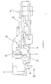
- a buckle housing 1 attached to safety belt webbing (not shown) by a rivet 2.
- the housing 1 has a passage ( Figures 4 and 5) 4 to receive a locking tongue (not shown) which is attached to another length of belt webbing (not shown).
- the locking tongue is held in the passage 4 by a latching element or lockbar 6 which is carried by a carrier member 7.
- Unlatching of the buckle is achieved by depressing a sliding button 9 in the direction of arrow 10 (which corresponds to the direction in which the buckle is pulled rapidly during pretensioning, ie to the acceleration direction at the beginning of the pretensioning stroke). At the end of the pretensioning stroke the buckle comes to an abrupt halt and is thus subjected to a high force corresponding to the deceleration direction opposite to the arrow 10.
- the button 9 is operatively connected to, or incorporates a ramp member 11 which serves to lift the carrier member 7 and lockbar 6 out of the engagement position by pivoting them in as the button is depressed.
- the carrier member 7 has an upwardly extending arm 13.
- a button return spring 12 is attached at one end to a boss 14 on the button 9 and at the other end to a boss on a spring carrier 15 which forms an inertia member or counterbalance mass.
- the button return spring 12 serves to bias the lockbar 6 into engagement with the tongue.
- Upper and lower buckle covers 20 and 21 clip together over the internal parts to prevent ingress of dirt and dust.
- the spring carrier 15 is formed with a cut away portion 19 which receives the upwardly extending arm 13 of the carrier 7 and by which the inertia of the spring carrier is transferred to the arm and thus to the carrier and lockbar to bias the lockbar into the engagement position and resist buckle release movement under conditions of high g-forces in the direction 10.
- the button movement to release the tongue is in the direction of arrow 10 and initially removes the overlock from the carrier assembly 7. Movement continues until the button ramps 11 contact and rotate the carrier assembly 7 by acting on forward arms 24 to turn pivot arms 22 on the carrier assembly 7 about pivot tubs 23 on the frame 1. This movement of the carrier assembly 8 also engages the spring carrier 15 at its contact point with the carrier assembly's vertical lever arm 13 and slides the spring carrier forward. Movement of the carrier assembly 7 continues up the button ramp 11 until it reaches the top of the ramp. At this point, when the tongue is in a release position, the forward button cam contacts the carrier assembly 7, rotating it to allow full forward movement of the tongue and ejector under the force of the ejector spring.
- the support bracket holding the spring carrier in a sliding motion is shown in Figure 5 where the elongate recesses 27 in the spring carrier 15 are engaged by a spring carrier support bracket 28. Bracket 28 is held in the buckle housing by rivet 2.
- the spring carrier 15 arranged to be significantly heavier than the button and thus biases the carrier assembly 7 and the lockbar 6 into its tongue engaging position on deceleration.
- This buckle has an increased performance ceiling compared to known buckles.
- This new buckle is a totally balanced system and does not rely on sensing or blocking. It is therefore more reliable and less prone to wear and fatigue failure since under normal conditions counterweight parts do not move.
Landscapes
- Automotive Seat Belt Assembly (AREA)
- Buckles (AREA)
Description
Claims (6)
- A buckle for a vehicle safety restraint seat belt comprising:a housing (1),a buckle part connected to one end of a seat belt and having a passage (4) for receiving an interlocking tongue part connected to another end of a seat belt,a pivoting carrier element (7) carrying a latching element (6) arranged to engage with the tongue part to lock the tongue part in the passage,a release button (9) operatively coupled via a ramp surface (11) to move the latching element (6) from an engaging position in which the buckle is fastened to the tongue, to a release position in which the buckle is unfastened,a counterbalance mass (15) slidably mounted in the housing (1) so that its inertia acts on the latching element (6) to keep the latching element (6) in the tongue engaging position under forces of acceleration and of deceleration acting on the buckle, the inertia acting in a first direction under acceleration and in a second direction under deceleration thereby substantially to counteract the effects of button inertia on the operation of the buckle.
- A buckle according to claim 1 wherein the counterbalance mass is resiliently connected to the release button.
- A buckle according to claim 2 wherein the counterbalance mass comprises a slidably mounted spring carrier having a boss carrying one end of a button return spring.
- A buckle according to claim 3 wherein the spring carrier is formed with channels which engage support brackets attached to the buckle housing so as to constrain the spring carrier against pivotal movement.
- A buckle according to claim 4 wherein the spring carrier is riveted to the buckle housing.
- A buckle according any one of the preceding claims wherein the carrier element is pivotally attached with respect to the buckle housing.
Applications Claiming Priority (3)
| Application Number | Priority Date | Filing Date | Title |
|---|---|---|---|
| GB9703219A GB2322158B (en) | 1997-02-17 | 1997-02-17 | Buckle |
| GB9703219 | 1997-02-17 | ||
| PCT/GB1998/000476 WO1998038882A1 (en) | 1997-02-17 | 1998-02-16 | Buckle |
Publications (2)
| Publication Number | Publication Date |
|---|---|
| EP0959707A1 EP0959707A1 (en) | 1999-12-01 |
| EP0959707B1 true EP0959707B1 (en) | 2003-04-16 |
Family
ID=10807772
Family Applications (1)
| Application Number | Title | Priority Date | Filing Date |
|---|---|---|---|
| EP98905501A Expired - Lifetime EP0959707B1 (en) | 1997-02-17 | 1998-02-16 | Buckle |
Country Status (6)
| Country | Link |
|---|---|
| US (1) | US6205628B1 (en) |
| EP (1) | EP0959707B1 (en) |
| JP (1) | JP3736858B2 (en) |
| DE (1) | DE69813509T2 (en) |
| GB (1) | GB2322158B (en) |
| WO (1) | WO1998038882A1 (en) |
Families Citing this family (11)
| Publication number | Priority date | Publication date | Assignee | Title |
|---|---|---|---|---|
| US7370393B2 (en) * | 2004-09-20 | 2008-05-13 | Delphi Technologies, Inc. | Seat belt buckle for use with pretensioner |
| WO2006127375A1 (en) | 2005-05-26 | 2006-11-30 | Delphi Technologies, Inc. | Seat belt buckle for use with pretensioner |
| JP5688256B2 (en) * | 2009-10-28 | 2015-03-25 | 芦森工業株式会社 | Buckle device |
| US8402617B2 (en) * | 2011-03-16 | 2013-03-26 | Liang-Hsiung Wang | Sand-removing seat belt buckle |
| DE102012018070A1 (en) * | 2012-02-07 | 2013-08-08 | Trw Automotive Gmbh | Belt lock with release lock |
| US9635909B2 (en) | 2012-08-31 | 2017-05-02 | Carleton Life Support Systems Inc. | Buckle release mechanism |
| EP3307106B1 (en) * | 2015-06-11 | 2021-08-04 | Cobham Mission Systems Davenport LSS Inc. | Buckle release mechanism |
| US10703327B2 (en) * | 2018-02-07 | 2020-07-07 | Ford Global Technologies, Llc | Seatbelt assembly |
| CN110870604B (en) * | 2020-01-19 | 2020-04-14 | 江苏智凯汽车安全系统有限公司 | Safety belt lock catch with electromagnetic safety function |
| CN112056707B (en) * | 2020-08-27 | 2024-06-25 | 浙江松原汽车安全系统股份有限公司 | A balance weight and a safety belt buckle |
| CN113944384A (en) * | 2021-12-20 | 2022-01-18 | 宁波福尔达智能科技股份有限公司 | Lock catch mechanism and storage box |
Family Cites Families (14)
| Publication number | Priority date | Publication date | Assignee | Title |
|---|---|---|---|---|
| DE3331467C2 (en) * | 1983-08-31 | 1986-10-16 | TRW Repa GmbH, 7077 Alfdorf | Buckle for a seat belt |
| US4766654A (en) * | 1984-10-19 | 1988-08-30 | Katsuyama Kinzoku Kogyo Kabushiki Kaisha | Push button buckle assembly for a seat belt |
| NO155871C (en) * | 1985-03-28 | 1987-06-17 | Loyd S Industri As | LOCK FOR SAFETY BELTS AND SIMILAR. |
| DE3833483A1 (en) * | 1988-10-01 | 1990-04-05 | Autoflug Gmbh | BELT LOCK WITH BALANCING |
| GB2227513B (en) * | 1988-11-08 | 1993-02-10 | Gen Engineering | Improvements in or relating to a safety belt buckle |
| GB8904205D0 (en) * | 1989-02-23 | 1989-04-05 | Bsrd Ltd | Seat belt buckle |
| DE59202428D1 (en) * | 1991-04-03 | 1995-07-13 | Autoliv Dev | Shockproof seat belt buckle. |
| GB9204793D0 (en) * | 1992-03-05 | 1992-04-15 | Bsrd Ltd | Seat belt buckle |
| DE4401291C1 (en) * | 1994-01-18 | 1995-02-02 | Hs Tech & Design | Safety belt fastener |
| DE4414924C2 (en) * | 1994-04-28 | 1997-02-27 | Hs Tech & Design | Seat belt buckle |
| DE4416301A1 (en) * | 1994-05-09 | 1995-11-16 | Trw Repa Gmbh | Seat belt buckle |
| GB9409246D0 (en) * | 1994-05-10 | 1994-06-29 | Alliedsignal Ltd | Buckle mechanism |
| US5496068A (en) * | 1995-01-20 | 1996-03-05 | Trw Vehicle Safety Systems Inc. | Inertia sensitive buckle for seat belt pretensioner system |
| US5522619A (en) * | 1995-02-01 | 1996-06-04 | Alliedsignal Inc. | End release seat belt buckle having an inertia-sensitive locking mechanism |
-
1997
- 1997-02-17 GB GB9703219A patent/GB2322158B/en not_active Revoked
-
1998
- 1998-02-16 JP JP53824998A patent/JP3736858B2/en not_active Expired - Fee Related
- 1998-02-16 WO PCT/GB1998/000476 patent/WO1998038882A1/en not_active Ceased
- 1998-02-16 US US09/341,624 patent/US6205628B1/en not_active Expired - Fee Related
- 1998-02-16 EP EP98905501A patent/EP0959707B1/en not_active Expired - Lifetime
- 1998-02-16 DE DE69813509T patent/DE69813509T2/en not_active Expired - Fee Related
Also Published As
| Publication number | Publication date |
|---|---|
| GB2322158A (en) | 1998-08-19 |
| GB9703219D0 (en) | 1997-04-09 |
| DE69813509D1 (en) | 2003-05-22 |
| DE69813509T2 (en) | 2004-03-04 |
| GB2322158B (en) | 2001-09-26 |
| JP2001513732A (en) | 2001-09-04 |
| WO1998038882A1 (en) | 1998-09-11 |
| US6205628B1 (en) | 2001-03-27 |
| JP3736858B2 (en) | 2006-01-18 |
| EP0959707A1 (en) | 1999-12-01 |
Similar Documents
| Publication | Publication Date | Title |
|---|---|---|
| US5213365A (en) | Inertially locking buckle for seat pretensioner | |
| US5152552A (en) | Emergency tensioning device for automotive seat belt | |
| US5332263A (en) | Actuating means for a buckle in a safety belt system | |
| US6205628B1 (en) | Buckle | |
| KR100691342B1 (en) | Buckle device | |
| EP1011360B1 (en) | Safety belt buckle | |
| US4404715A (en) | Safety-belt buckle of slide-unlocking type | |
| US4840404A (en) | Seat belt system having shoulder height support | |
| US5309611A (en) | Buckle for vehicle safety belt systems | |
| US5023980A (en) | Free running cinching latch plate | |
| US7146692B2 (en) | Non-inertial release safety restraint belt buckle systems | |
| EP0907332B1 (en) | Seat belt buckle | |
| US4536010A (en) | Automatic seatbelt system | |
| US6370742B1 (en) | Buckle with movement prevention device | |
| GB2073810A (en) | Improvements in or relating to a buckle | |
| US5374080A (en) | Safety belt pretensioner for safety belt systems in vehicles | |
| MX2007007338A (en) | Non-inertial release safety restraint belt buckle. | |
| EP1374714B1 (en) | Safety belt buckle | |
| JPH05278564A (en) | Buckle for safety buckle | |
| GB2313152A (en) | A G-force proof buckle mechanism for a seat belt pretensioner arrangement | |
| US6088890A (en) | Safety belt buckle | |
| EP0385232A1 (en) | Comfort feature | |
| GB2314879A (en) | Safety belt buckle with release button counterweight guided by cam | |
| EP0567303A1 (en) | Safety restraint pretensioning | |
| GB2328244A (en) | Safety belt buckle for use with a pretensioner |
Legal Events
| Date | Code | Title | Description |
|---|---|---|---|
| PUAI | Public reference made under article 153(3) epc to a published international application that has entered the european phase |
Free format text: ORIGINAL CODE: 0009012 |
|
| 17P | Request for examination filed |
Effective date: 19990713 |
|
| AK | Designated contracting states |
Kind code of ref document: A1 Designated state(s): DE ES FR GB IT SE |
|
| GRAG | Despatch of communication of intention to grant |
Free format text: ORIGINAL CODE: EPIDOS AGRA |
|
| GRAG | Despatch of communication of intention to grant |
Free format text: ORIGINAL CODE: EPIDOS AGRA |
|
| GRAH | Despatch of communication of intention to grant a patent |
Free format text: ORIGINAL CODE: EPIDOS IGRA |
|
| 17Q | First examination report despatched |
Effective date: 20020415 |
|
| GRAH | Despatch of communication of intention to grant a patent |
Free format text: ORIGINAL CODE: EPIDOS IGRA |
|
| GRAA | (expected) grant |
Free format text: ORIGINAL CODE: 0009210 |
|
| AK | Designated contracting states |
Designated state(s): DE ES FR GB IT SE |
|
| REG | Reference to a national code |
Ref country code: GB Ref legal event code: FG4D |
|
| REF | Corresponds to: |
Ref document number: 69813509 Country of ref document: DE Date of ref document: 20030522 Kind code of ref document: P |
|
| PG25 | Lapsed in a contracting state [announced via postgrant information from national office to epo] |
Ref country code: SE Free format text: LAPSE BECAUSE OF FAILURE TO SUBMIT A TRANSLATION OF THE DESCRIPTION OR TO PAY THE FEE WITHIN THE PRESCRIBED TIME-LIMIT Effective date: 20030716 |
|
| ET | Fr: translation filed | ||
| PG25 | Lapsed in a contracting state [announced via postgrant information from national office to epo] |
Ref country code: ES Free format text: LAPSE BECAUSE OF FAILURE TO SUBMIT A TRANSLATION OF THE DESCRIPTION OR TO PAY THE FEE WITHIN THE PRESCRIBED TIME-LIMIT Effective date: 20031030 |
|
| RAP2 | Party data changed (patent owner data changed or rights of a patent transferred) |
Owner name: BREED AUTOMOTIVE TECHNOLOGY, INC. |
|
| PLBE | No opposition filed within time limit |
Free format text: ORIGINAL CODE: 0009261 |
|
| STAA | Information on the status of an ep patent application or granted ep patent |
Free format text: STATUS: NO OPPOSITION FILED WITHIN TIME LIMIT |
|
| 26N | No opposition filed |
Effective date: 20040119 |
|
| REG | Reference to a national code |
Ref country code: GB Ref legal event code: 732E |
|
| REG | Reference to a national code |
Ref country code: FR Ref legal event code: TP |
|
| PGFP | Annual fee paid to national office [announced via postgrant information from national office to epo] |
Ref country code: GB Payment date: 20070105 Year of fee payment: 10 |
|
| PGFP | Annual fee paid to national office [announced via postgrant information from national office to epo] |
Ref country code: DE Payment date: 20070228 Year of fee payment: 10 |
|
| PGFP | Annual fee paid to national office [announced via postgrant information from national office to epo] |
Ref country code: IT Payment date: 20070526 Year of fee payment: 10 |
|
| PGFP | Annual fee paid to national office [announced via postgrant information from national office to epo] |
Ref country code: FR Payment date: 20070201 Year of fee payment: 10 |
|
| GBPC | Gb: european patent ceased through non-payment of renewal fee |
Effective date: 20080216 |
|
| REG | Reference to a national code |
Ref country code: FR Ref legal event code: ST Effective date: 20081031 |
|
| PG25 | Lapsed in a contracting state [announced via postgrant information from national office to epo] |
Ref country code: DE Free format text: LAPSE BECAUSE OF NON-PAYMENT OF DUE FEES Effective date: 20080902 |
|
| PG25 | Lapsed in a contracting state [announced via postgrant information from national office to epo] |
Ref country code: FR Free format text: LAPSE BECAUSE OF NON-PAYMENT OF DUE FEES Effective date: 20080229 |
|
| PG25 | Lapsed in a contracting state [announced via postgrant information from national office to epo] |
Ref country code: GB Free format text: LAPSE BECAUSE OF NON-PAYMENT OF DUE FEES Effective date: 20080216 |
|
| PG25 | Lapsed in a contracting state [announced via postgrant information from national office to epo] |
Ref country code: IT Free format text: LAPSE BECAUSE OF NON-PAYMENT OF DUE FEES Effective date: 20080216 |