EP0959365B1 - MRI shimset and gradient coil with cutout portions formed therein - Google Patents
MRI shimset and gradient coil with cutout portions formed therein Download PDFInfo
- Publication number
- EP0959365B1 EP0959365B1 EP99108413A EP99108413A EP0959365B1 EP 0959365 B1 EP0959365 B1 EP 0959365B1 EP 99108413 A EP99108413 A EP 99108413A EP 99108413 A EP99108413 A EP 99108413A EP 0959365 B1 EP0959365 B1 EP 0959365B1
- Authority
- EP
- European Patent Office
- Prior art keywords
- shimset
- gradient coil
- cutout portion
- cutout portions
- magnetic field
- Prior art date
- Legal status (The legal status is an assumption and is not a legal conclusion. Google has not performed a legal analysis and makes no representation as to the accuracy of the status listed.)
- Expired - Lifetime
Links
- 238000002595 magnetic resonance imaging Methods 0.000 claims description 21
- XEEYBQQBJWHFJM-UHFFFAOYSA-N Iron Chemical compound [Fe] XEEYBQQBJWHFJM-UHFFFAOYSA-N 0.000 description 20
- 229910052742 iron Inorganic materials 0.000 description 10
- 230000000694 effects Effects 0.000 description 5
- 239000000696 magnetic material Substances 0.000 description 5
- 238000000034 method Methods 0.000 description 5
- 238000012938 design process Methods 0.000 description 2
- 230000015556 catabolic process Effects 0.000 description 1
- 230000002860 competitive effect Effects 0.000 description 1
- 239000004020 conductor Substances 0.000 description 1
- 238000010276 construction Methods 0.000 description 1
- 238000006731 degradation reaction Methods 0.000 description 1
Images

Classifications
-
- G—PHYSICS
- G01—MEASURING; TESTING
- G01R—MEASURING ELECTRIC VARIABLES; MEASURING MAGNETIC VARIABLES
- G01R33/00—Arrangements or instruments for measuring magnetic variables
- G01R33/20—Arrangements or instruments for measuring magnetic variables involving magnetic resonance
- G01R33/28—Details of apparatus provided for in groups G01R33/44 - G01R33/64
- G01R33/38—Systems for generation, homogenisation or stabilisation of the main or gradient magnetic field
- G01R33/387—Compensation of inhomogeneities
- G01R33/3875—Compensation of inhomogeneities using correction coil assemblies, e.g. active shimming
Definitions
- the present invention relates to improvements in or relating to magnetic resonance imaging (MRI) systems, and is more particularly concerned with the construction of shimming apparatus for use therewith.
- MRI magnetic resonance imaging
- a MRI system consists of a magnet which provides a main magnetic field, a gradient coil to superimpose a linearly varying field over the main field, and an RF coil transmit/receive system which is used to receive the signals that are used to construct the image.
- a good base homogeneity of the main magnetic field in the system is essential for producing good quality images, and hence the process of shimming has been developed in order to establish good base homogeneity.
- Shimming is the process by which the field in an MRI magnet is corrected. It is an essential activity, without which the system cannot function. Correction of magnetic field deviations can be performed using any elements that produce a magnetic field. Thus, current carrying conductors, soft iron in the presence of a magnetic field, and permanent magnets have been known to be used. For MRI magnets, passive shimming is extensively used. Passive shimming is defined as the use of magnetic material elements, be they soft iron or permanent magnets, for the correction of magnetic fields. The use of passive shimming is extensive because it is simple, cheap and can achieve high levels of homogeneity.
- Passive shimming requires the placing of magnetic material in one or more positions around the bore of a magnet in order to perform the field correction.
- the process takes the form of a field map of the region of interest, normally defined as a spherical volume.
- the field values are then decomposed into, as is well known in the art, spherical harmonics, which describe the field variation over the volume.
- spherical harmonics which describe the field variation over the volume.
- the shimset is no more than the hardware needed to locate the precise distribution of magnetic material used to correct inhomegeneities in the magnetic field.
- one or more trays are distributed azimuthally over the shimset, each tray having a series of pockets in which shim iron can be placed (see, for instance, EP-A-0 710 951).
- the quantity of shim iron in each pocket depends on the inhomogeneity of the magnetic field. Axial and azimuthal symmetry have traditionally been used in the design of shimsets and there has been no need to deviate from that.
- United States patent 5,177,441 discloses an MRI system with a gradient coil of oval-shaped cross-section.
- United States patent 5,708,360 discloses an MRI system having a gradient coil with cut-outs for accommodating a patient's shoulders.
- An aim of the present invention is to provide an MRI system which does not require axial and azimuthal symmetry in the shimming.
- the MRI system according to the present invention has the advantage of accommodating larger patients without the need to increase the bore size of the magnet because the cutout portions provided accommodate the shoulders of larger patients.
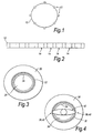
- FIG 1 illustrates a shimset 10 for a magnet (not shown) around which a plurality of shim trays 12 are distributed azimuthally.
- a shim tray 12 is shown in Figure 2.
- each tray 12 has a series of pockets 14 in which shim iron can be placed. The quantity of shim iron placed in each pocket 14 depends on the inhomogeneity of the magnetic field.
- the magnet 20 includes a shimset 22, and a gradient coil 24 as shown.
- the shimset 22 takes the form as shown in Figures 1 and 2.
- a patient lies within bore 26 of the MRI system and within the magnet 20. Therefore, the size of the bore 26 determines the maximum size of the patient which can be accommodated within the magnet 20 because the shoulders of the patient have to fit within the bore 26.
- the cost of MRI systems depends upon the physical size of the system. To accommodate larger patients by providing a larger bore would increase the physical size of the MRI systems and hence the cost.
- an MRI system as shown in Figure 4 which comprises a magnet 30, a shimset 32, a gradient coil 34 and a bore 36.
- the shimset 32 has a pair of diametrically opposed cutout portions 38. Similar cutout portions 40 are provided in the gradient coil 34 and are aligned with the cutout portions 38 in the shimset 32. This means that a larger patient 42 can be accommodated in the bore 36 by utilising the cutout portions 38, 40 to accommodate the shoulders of the patient 42.
- the shimset 32 and the gradient coil 34 are constructed so that they do not have axial and azimuthal symmetry.
- FIG. 5 An isometric view of a part 50 of an MR system according to the present invention is shown in Figure 5.
- the part 50 comprises a shimset 52 having a plurality of shim trays arranged around its periphery, only two shim trays 54, 56 being shown for clarity, and a gradient coil 58.
- each of the shimset 52 and the gradient coil 58 has similar cutout portions 60, 62 aligned with one another.
- cutout portions 60, 62 it is not necessary for the cutout portions 60, 62 to extend the entire length of the magnet system.
- the actual length of the cutout is defined by the particular application and may extend along a substantial part of the length of the magnet or even the entire length thereof.
- the shimset which is to be used with the magnet described with reference to Figure 4 may be determined as follows:
- the next step is to determine whether the cutouts will cause any degradation in the shimmed homogeneity. This can be achieved by determining the pockets which would not be available as a result of the cutouts and performing the analysis as above with those specific pockets removed from the optimisation process. In this way, the effect of the cutout can be evaluated.
- the optimisation process requires the minimisation of a merit function which is indicative of the homogeneity of the magnetic field.
- the merit function ( ⁇ ) used is the weighted sum of the squares of the harmonics and can be expressed as:- where W ij is the weight and A i j and B i j are the harmonics.
- the weights are appropriately selected so that the important harmonics are weighted more than the unimportant ones.
- the use of harmonics is important because the inadequacy of shim design will be reflected in the remnant harmonics.
- the shimming capability is evaluated by shimming theoretical data plots generated from a host of harmonics that are typical and atypical of the magnet.
- the shimset consisted of 24 trays each having 17 pockets.
- the pockets in each tray had a depth of about 6mm enabling a maximum stack height of 6mm of iron to be placed in each pocket.
- the trays were placed on a diameter of about 590mm and the full length of the shimset was 890mm.
- the depth of the cutouts was 355mm. It will readily be appreciated that the asymmetry was significant.
- the shimset was used to shim a magnet from about 346ppm (parts per million) down to less than 1ppm on a spherical volume of diameter 22cm.
- the harmonic combination was such that the mass of iron required to shim the magnet was about 10 per cent higher than the case where there are no cutouts.
- the maximum stack height installed increased by about 25 per cent.
- the design process can be applied to any number of cutouts, though that will naturally limit the harmonics that can be shimmed out. Also, the design process can accommodate cutouts of different lengths, and full length cutouts.
Landscapes
- Physics & Mathematics (AREA)
- Condensed Matter Physics & Semiconductors (AREA)
- General Physics & Mathematics (AREA)
- Magnetic Resonance Imaging Apparatus (AREA)
Description
- The present invention relates to improvements in or relating to magnetic resonance imaging (MRI) systems, and is more particularly concerned with the construction of shimming apparatus for use therewith.
- A MRI system consists of a magnet which provides a main magnetic field, a gradient coil to superimpose a linearly varying field over the main field, and an RF coil transmit/receive system which is used to receive the signals that are used to construct the image. A good base homogeneity of the main magnetic field in the system is essential for producing good quality images, and hence the process of shimming has been developed in order to establish good base homogeneity.
- Shimming is the process by which the field in an MRI magnet is corrected. It is an essential activity, without which the system cannot function. Correction of magnetic field deviations can be performed using any elements that produce a magnetic field. Thus, current carrying conductors, soft iron in the presence of a magnetic field, and permanent magnets have been known to be used. For MRI magnets, passive shimming is extensively used. Passive shimming is defined as the use of magnetic material elements, be they soft iron or permanent magnets, for the correction of magnetic fields. The use of passive shimming is extensive because it is simple, cheap and can achieve high levels of homogeneity.
- Passive shimming requires the placing of magnetic material in one or more positions around the bore of a magnet in order to perform the field correction. Traditionally, the process takes the form of a field map of the region of interest, normally defined as a spherical volume. The field values are then decomposed into, as is well known in the art, spherical harmonics, which describe the field variation over the volume. Thus, two elements are required to effect passive shimming, namely, the software which is used to predict the positions of the pieces of magnetic material necessary to perform the field correction, and the hardware, called the shimset, comprising pieces of magnetic material which are appropriately positioned to effect the field correction.
- For normal coil wound magnets (also known as solenoidal magnets), the shimset is no more than the hardware needed to locate the precise distribution of magnetic material used to correct inhomegeneities in the magnetic field. In practice, one or more trays are distributed azimuthally over the shimset, each tray having a series of pockets in which shim iron can be placed (see, for instance, EP-A-0 710 951). The quantity of shim iron in each pocket depends on the inhomogeneity of the magnetic field. Axial and azimuthal symmetry have traditionally been used in the design of shimsets and there has been no need to deviate from that.
- United States patent 5,177,441 discloses an MRI system with a gradient coil of oval-shaped cross-section.
- United States patent 5,708,360 discloses an MRI system having a gradient coil with cut-outs for accommodating a patient's shoulders.
- An aim of the present invention is to provide an MRI system which does not require axial and azimuthal symmetry in the shimming.
- According to one aspect of the present invention, there is provided a shimset and a magnetic resonance imaging system as defined in the appended claims.
- The MRI system according to the present invention has the advantage of accommodating larger patients without the need to increase the bore size of the magnet because the cutout portions provided accommodate the shoulders of larger patients. For a better understanding of the present invention, reference will now be made, by way of example only, to the accompanying drawings in which:-
- FIGURE 1 shows the distribution of shim trays within an MRI system;
- FIGURE 2 shows a shim tray;
- FIGURE 3 is a cross-section of a known MRI system;
- FIGURE 4 shows a cross-section of an MRI system according to the present invention; and
- FIGURE 5 shows an isometric view of part of an MRI system according to the present invention.
-
- Figure 1 illustrates a
shimset 10 for a magnet (not shown) around which a plurality ofshim trays 12 are distributed azimuthally. Ashim tray 12 is shown in Figure 2. As shown eachtray 12 has a series ofpockets 14 in which shim iron can be placed. The quantity of shim iron placed in eachpocket 14 depends on the inhomogeneity of the magnetic field. - Referring now to Figure 3, the normal structure of a known
MRI magnet 20. Themagnet 20 includes ashimset 22, and agradient coil 24 as shown. Theshimset 22 takes the form as shown in Figures 1 and 2. In use, a patient lies withinbore 26 of the MRI system and within themagnet 20. Therefore, the size of thebore 26 determines the maximum size of the patient which can be accommodated within themagnet 20 because the shoulders of the patient have to fit within thebore 26. - The cost of MRI systems depends upon the physical size of the system. To accommodate larger patients by providing a larger bore would increase the physical size of the MRI systems and hence the cost.
- This problem is overcome by the provision of an MRI system as shown in Figure 4 which comprises a
magnet 30, ashimset 32, agradient coil 34 and abore 36. Theshimset 32 has a pair of diametrically opposed cutout portions 38. Similar cutout portions 40 are provided in thegradient coil 34 and are aligned with the cutout portions 38 in theshimset 32. This means that alarger patient 42 can be accommodated in thebore 36 by utilising the cutout portions 38, 40 to accommodate the shoulders of thepatient 42. - Therefore, the
shimset 32 and thegradient coil 34 are constructed so that they do not have axial and azimuthal symmetry. - An isometric view of a
part 50 of an MR system according to the present invention is shown in Figure 5. Thepart 50 comprises a shimset 52 having a plurality of shim trays arranged around its periphery, only twoshim trays gradient coil 58. In accordance with the present invention, each of theshimset 52 and thegradient coil 58 has similar cutout portions 60, 62 aligned with one another. - By using cutouts and being able to effect passive shimming with the presence of cutouts, the need to increase the bore size of the magnet has been eliminated. This provides an MRI system in accordance the present invention with a competitive advantage, both in terms of price and size as any increase in size will demand a longer magnet and more wire, thereby increasing the cost of the system.
- As shown in Figure 5, it is not necessary for the cutout portions 60, 62 to extend the entire length of the magnet system. The actual length of the cutout is defined by the particular application and may extend along a substantial part of the length of the magnet or even the entire length thereof.
- The embodiments described above illustrate the use of two cutouts. However, there is no reason to limit the design to two cutouts if the application requires a different number of cutouts. For example, it may desired to have a single cutout and to have the patient offset with respect to the longitudinal axis of the bore.
- The shimset which is to be used with the magnet described with reference to Figure 4 may be determined as follows:
- A complete shimset is designed without cutouts. Hence axial and azimuthal symmetry is assumed. This enables the optimal design for shimming harmonics which are either inherent or due to build errors thereby providing the most suitable distribution of trays and pockets as described above.
- The next step is to determine whether the cutouts will cause any degradation in the shimmed homogeneity. This can be achieved by determining the pockets which would not be available as a result of the cutouts and performing the analysis as above with those specific pockets removed from the optimisation process. In this way, the effect of the cutout can be evaluated.
- The optimisation process requires the minimisation of a merit function which is indicative of the homogeneity of the magnetic field. The merit function () used is the weighted sum of the squares of the harmonics and can be expressed as:-where Wij is the weight and Ai j and Bi j are the harmonics.

- The weights are appropriately selected so that the important harmonics are weighted more than the unimportant ones. The use of harmonics is important because the inadequacy of shim design will be reflected in the remnant harmonics. The shimming capability is evaluated by shimming theoretical data plots generated from a host of harmonics that are typical and atypical of the magnet.
- In a specific application in accordance with the present invention, the shimset consisted of 24 trays each having 17 pockets. The pockets in each tray had a depth of about 6mm enabling a maximum stack height of 6mm of iron to be placed in each pocket. The trays were placed on a diameter of about 590mm and the full length of the shimset was 890mm. The depth of the cutouts was 355mm. It will readily be appreciated that the asymmetry was significant. The shimset was used to shim a magnet from about 346ppm (parts per million) down to less than 1ppm on a spherical volume of diameter 22cm.
- For the above example, the harmonic combination was such that the mass of iron required to shim the magnet was about 10 per cent higher than the case where there are no cutouts. However, the maximum stack height installed increased by about 25 per cent.
- Because of the inability to place the iron in the region of the cutout, the optimisation results in increased mass and stack height in other pockets. Thus the penalty incurred as a consequence of employing cutouts is more iron and greater stack heights in the pockets.
- As mentioned above, the design process can be applied to any number of cutouts, though that will naturally limit the harmonics that can be shimmed out. Also, the design process can accommodate cutouts of different lengths, and full length cutouts.
Claims (7)
- A shimset (32; 52) for a magnetic resonance imaging system comprising a former (50) with a central bore (36) for the object to be analysed, the former carrying trays (12) and pockets (14) for passive shims, characterised in that the former has at least one cutout portion (38; 60, 62) at one end thereof, such that a larger object (42) can be accommodate within the bore.
- A shimset according to claim 1, including two cutout portions (38) which are diametrically opposite each other.
- A shimset according to any preceding claim wherein the or each cutout portion contains no shims, and the shims of said shimset outside of the or each cutout portion are adapted to compensate for the absence of shims in the cutout portion(s).
- A magnetic resonance imaging system comprising a magnet (30) for generating a main magnetic field, a shimset (32) for homogenising the main magnetic field, a gradient coil (34) for superimposing a linearly varying magnetic field over the main magnetic field, and an RF coil (34) forming part of a transmit/receive system for signals which are used to construct an image, characterised in that the shimset (32) is as defined in any preceding claim.
- A system according to claim 4, wherein the shimset (32) and the gradient coil (34) each have at least one cutout portion (38, 40).
- A system according to claim 4, wherein the gradient coil (34) includes at least one cutout portion (40) which matches said at least one cutout portion (38) in the shimset (32).
- A system according to claim 6, wherein the shimset (32) and the gradient coil (34) each have two cutout portions (38, 40) which are diametrically opposite each other, the cutout portions (40) of the gradient coil (34) being aligned with the cutout portions (38) of the shimset means (32).
Applications Claiming Priority (2)
| Application Number | Priority Date | Filing Date | Title |
|---|---|---|---|
| GB9810976 | 1998-05-22 | ||
| GB9810976A GB2337595B (en) | 1998-05-22 | 1998-05-22 | Improvements in or relating to magnetic resonance imaging systems |
Publications (3)
| Publication Number | Publication Date |
|---|---|
| EP0959365A2 EP0959365A2 (en) | 1999-11-24 |
| EP0959365A3 EP0959365A3 (en) | 2001-08-01 |
| EP0959365B1 true EP0959365B1 (en) | 2005-06-29 |
Family
ID=10832502
Family Applications (1)
| Application Number | Title | Priority Date | Filing Date |
|---|---|---|---|
| EP99108413A Expired - Lifetime EP0959365B1 (en) | 1998-05-22 | 1999-04-29 | MRI shimset and gradient coil with cutout portions formed therein |
Country Status (5)
| Country | Link |
|---|---|
| US (1) | US6218839B1 (en) |
| EP (1) | EP0959365B1 (en) |
| JP (1) | JP4191319B2 (en) |
| DE (1) | DE69925956T2 (en) |
| GB (1) | GB2337595B (en) |
Families Citing this family (11)
| Publication number | Priority date | Publication date | Assignee | Title |
|---|---|---|---|---|
| US6754894B1 (en) | 1999-12-03 | 2004-06-22 | Command Audio Corporation | Wireless software and configuration parameter modification for mobile electronic devices |
| DE10147984B4 (en) * | 2001-09-28 | 2007-10-11 | Siemens Ag | Magnetic resonance examination apparatus with a device for generating a homogeneous magnetic field and method for improving the homogeneity of a magnetic field |
| US6984982B2 (en) * | 2002-07-29 | 2006-01-10 | Ge Medical Systems Global Technology Company Llc | Method and system for shimming an MRI magnet assembly |
| US6836119B2 (en) * | 2002-10-15 | 2004-12-28 | Koninklijke Philips Electronics, N.V. | Method and apparatus for aligning a magnetic field modifying structure in a magnetic resonance imaging scanner |
| JP4767688B2 (en) * | 2003-10-15 | 2011-09-07 | 株式会社日立メディコ | Magnetic resonance imaging system |
| US7295012B1 (en) | 2006-04-28 | 2007-11-13 | General Electric Company | Methods and apparatus for MRI shim elements |
| US7446532B1 (en) | 2007-07-18 | 2008-11-04 | Varian, Inc. | Arched saddle-shaped NMR RF coils |
| CA2780181C (en) * | 2009-12-02 | 2019-10-15 | Nanalysis Corp. | Method and apparatus for producing homogeneous magnetic fields |
| DE102010041580A1 (en) * | 2010-09-29 | 2012-03-29 | Siemens Aktiengesellschaft | Magnetic resonance device for use with radiation therapy device during radiation therapy of patient, has coil arrangements with partial sections that are separated such that patient retainer radius is extended into region upto bore edge |
| KR101682198B1 (en) * | 2013-08-13 | 2016-12-02 | 삼성전자주식회사 | Magnetic resonance imaging device and manufacturing method thereof |
| CN108802644B (en) * | 2018-05-24 | 2020-09-15 | 上海东软医疗科技有限公司 | Shimming method and device for gradient coil |
Family Cites Families (14)
| Publication number | Priority date | Publication date | Assignee | Title |
|---|---|---|---|---|
| GB8402360D0 (en) * | 1984-01-30 | 1984-02-29 | Picker Int Ltd | Nmr shims |
| EP0303880B1 (en) * | 1987-08-14 | 1991-11-06 | Siemens Aktiengesellschaft | Electromagnet for nuclear spin tomography |
| US4803433A (en) * | 1987-12-21 | 1989-02-07 | Montefiore Hospital Association Of Western Pennsylvania, Inc. | Method and apparatus for shimming tubular supermagnets |
| US4853663A (en) * | 1988-12-22 | 1989-08-01 | General Electric Company | Passive shims for correction of (3,2) and (3,-2) harmonic terms in magnetic resonance magnets |
| US5177441A (en) * | 1989-06-16 | 1993-01-05 | Picker International, Inc. | Elliptical cross section gradient oil |
| JPH05329128A (en) * | 1992-05-29 | 1993-12-14 | Mitsubishi Electric Corp | Magnetic field correction device |
| US5389909A (en) * | 1993-11-08 | 1995-02-14 | General Electric Company | Open architecture magnetic resonance imaging passively shimmed superconducting magnet assembly |
| US5485087A (en) * | 1994-08-05 | 1996-01-16 | Picker International, Inc. | Magnetic resonance insert gradient coils with parabolic returns for improved access |
| DE4416907C1 (en) * | 1994-05-13 | 1995-09-07 | Bruker Analytische Messtechnik | NMR Medical therapy tomograph with homogenising device |
| US5545997A (en) * | 1994-05-13 | 1996-08-13 | Bruker Analytische Messtechnik Gmbh | Therapy tomograph with homogeneity device |
| US5416415A (en) * | 1994-08-05 | 1995-05-16 | General Electric Company | Over-shoulder MRI magnet for human brain imaging |
| JPH0884716A (en) * | 1994-09-16 | 1996-04-02 | Toshiba Corp | Gradient magnetic field coil |
| US5635839A (en) * | 1994-11-04 | 1997-06-03 | Picker International, Inc. | High order passive shimming assembly for MRI magnets |
| GB9623537D0 (en) * | 1996-11-12 | 1997-01-08 | Marconi Gec Ltd | Nuclear magnetic resonance imaging apparatus |
-
1998
- 1998-05-22 GB GB9810976A patent/GB2337595B/en not_active Expired - Fee Related
-
1999
- 1999-04-29 DE DE69925956T patent/DE69925956T2/en not_active Expired - Fee Related
- 1999-04-29 EP EP99108413A patent/EP0959365B1/en not_active Expired - Lifetime
- 1999-05-21 JP JP14167299A patent/JP4191319B2/en not_active Expired - Fee Related
- 1999-05-24 US US09/317,425 patent/US6218839B1/en not_active Expired - Lifetime
Also Published As
| Publication number | Publication date |
|---|---|
| EP0959365A3 (en) | 2001-08-01 |
| DE69925956T2 (en) | 2006-01-05 |
| JPH11347013A (en) | 1999-12-21 |
| US6218839B1 (en) | 2001-04-17 |
| EP0959365A2 (en) | 1999-11-24 |
| GB9810976D0 (en) | 1998-07-22 |
| GB2337595B (en) | 2003-03-19 |
| DE69925956D1 (en) | 2005-08-04 |
| JP4191319B2 (en) | 2008-12-03 |
| GB2337595A (en) | 1999-11-24 |
Similar Documents
| Publication | Publication Date | Title |
|---|---|---|
| EP0216404B1 (en) | Magnetic resonance imaging apparatus including-homogenizing magnetic elements | |
| US4486711A (en) | Gradient field coil system for nuclear spin tomography | |
| US4758813A (en) | Cylindrical NMR bias magnet apparatus employing permanent magnets and methods therefor | |
| EP0231879B1 (en) | Self-shielded gradient coils for nuclear magnetic resonance imaging | |
| US5166619A (en) | Gradient coil assembly for a magnetic resonance imaging apparatus | |
| US4590452A (en) | Magnetic device of apparatus in nuclear spin tomography with a shielding device | |
| EP0826977B1 (en) | Compact MRI superconducting magnet | |
| EP0676647A1 (en) | Open MRI magnet | |
| US6456076B1 (en) | Z gradient shielding coil for canceling eddy currents | |
| JP3507519B2 (en) | Transversal gradient magnetic field coil | |
| JP2584005B2 (en) | Magnetic field gradient coil device and magnetic resonance imaging system using the same | |
| JPH09153408A (en) | Superconducting magnet device | |
| US4812797A (en) | Compensation coil for temporal drift of a superconducting magnet | |
| EP0162369B1 (en) | Axisymmetric correction coil stem for nmr magnets | |
| EP0701700A1 (en) | An acoustic screen | |
| EP0959365A2 (en) | MRI shimset and gradient coil with cutout portions formed therein | |
| US5568110A (en) | Closed MRI magnet having reduced length | |
| US4879538A (en) | Magnet system for nuclear magnetic resonance tomography devices | |
| US5594401A (en) | Closed superconductive magnet with uniform imaging volume | |
| US5568102A (en) | Closed superconductive magnet with homogeneous imaging volume | |
| US6084497A (en) | Superconducting magnets | |
| US6100692A (en) | Gradient coil set with a finite shield current | |
| US5814993A (en) | Magnet arrangement for a diagnostic nuclear magnetic resonance apparatus | |
| US20060181383A1 (en) | Magnet assembly | |
| US4799017A (en) | Background field magnet for image generating devices using nuclear spin resonance |
Legal Events
| Date | Code | Title | Description |
|---|---|---|---|
| PUAI | Public reference made under article 153(3) epc to a published international application that has entered the european phase |
Free format text: ORIGINAL CODE: 0009012 |
|
| 17P | Request for examination filed |
Effective date: 19990429 |
|
| AK | Designated contracting states |
Kind code of ref document: A2 Designated state(s): DE FR GB |
|
| AX | Request for extension of the european patent |
Free format text: AL;LT;LV;MK;RO;SI |
|
| PUAL | Search report despatched |
Free format text: ORIGINAL CODE: 0009013 |
|
| AK | Designated contracting states |
Kind code of ref document: A3 Designated state(s): AT BE CH CY DE DK ES FI FR GB GR IE IT LI LU MC NL PT SE |
|
| AX | Request for extension of the european patent |
Free format text: AL;LT;LV;MK;RO;SI |
|
| RIC1 | Information provided on ipc code assigned before grant |
Free format text: 7G 01R 33/3873 A, 7G 01R 33/385 B |
|
| AKX | Designation fees paid |
Free format text: DE FR GB |
|
| 17Q | First examination report despatched |
Effective date: 20031223 |
|
| GRAP | Despatch of communication of intention to grant a patent |
Free format text: ORIGINAL CODE: EPIDOSNIGR1 |
|
| GRAS | Grant fee paid |
Free format text: ORIGINAL CODE: EPIDOSNIGR3 |
|
| RAP1 | Party data changed (applicant data changed or rights of an application transferred) |
Owner name: SIEMENS MAGNET TECHNOLOGY LIMITED |
|
| GRAA | (expected) grant |
Free format text: ORIGINAL CODE: 0009210 |
|
| AK | Designated contracting states |
Kind code of ref document: B1 Designated state(s): DE FR GB |
|
| REG | Reference to a national code |
Ref country code: GB Ref legal event code: FG4D |
|
| REF | Corresponds to: |
Ref document number: 69925956 Country of ref document: DE Date of ref document: 20050804 Kind code of ref document: P |
|
| PGFP | Annual fee paid to national office [announced via postgrant information from national office to epo] |
Ref country code: DE Payment date: 20060427 Year of fee payment: 8 |
|
| PLBE | No opposition filed within time limit |
Free format text: ORIGINAL CODE: 0009261 |
|
| STAA | Information on the status of an ep patent application or granted ep patent |
Free format text: STATUS: NO OPPOSITION FILED WITHIN TIME LIMIT |
|
| 26N | No opposition filed |
Effective date: 20060330 |
|
| EN | Fr: translation not filed | ||
| PG25 | Lapsed in a contracting state [announced via postgrant information from national office to epo] |
Ref country code: FR Free format text: LAPSE BECAUSE OF FAILURE TO SUBMIT A TRANSLATION OF THE DESCRIPTION OR TO PAY THE FEE WITHIN THE PRESCRIBED TIME-LIMIT Effective date: 20060825 |
|
| PG25 | Lapsed in a contracting state [announced via postgrant information from national office to epo] |
Ref country code: DE Free format text: LAPSE BECAUSE OF NON-PAYMENT OF DUE FEES Effective date: 20071101 |
|
| PG25 | Lapsed in a contracting state [announced via postgrant information from national office to epo] |
Ref country code: FR Free format text: LAPSE BECAUSE OF FAILURE TO SUBMIT A TRANSLATION OF THE DESCRIPTION OR TO PAY THE FEE WITHIN THE PRESCRIBED TIME-LIMIT Effective date: 20050629 |
|
| REG | Reference to a national code |
Ref country code: GB Ref legal event code: 732E Free format text: REGISTERED BETWEEN 20090507 AND 20090513 |
|
| PGFP | Annual fee paid to national office [announced via postgrant information from national office to epo] |
Ref country code: GB Payment date: 20090409 Year of fee payment: 11 |
|
| GBPC | Gb: european patent ceased through non-payment of renewal fee |
Effective date: 20100429 |
|
| PG25 | Lapsed in a contracting state [announced via postgrant information from national office to epo] |
Ref country code: GB Free format text: LAPSE BECAUSE OF NON-PAYMENT OF DUE FEES Effective date: 20100429 |