EP0958512B1 - Apparatus and method for correcting for capacitance variations in hydrophones - Google Patents
Apparatus and method for correcting for capacitance variations in hydrophones Download PDFInfo
- Publication number
- EP0958512B1 EP0958512B1 EP98956347A EP98956347A EP0958512B1 EP 0958512 B1 EP0958512 B1 EP 0958512B1 EP 98956347 A EP98956347 A EP 98956347A EP 98956347 A EP98956347 A EP 98956347A EP 0958512 B1 EP0958512 B1 EP 0958512B1
- Authority
- EP
- European Patent Office
- Prior art keywords
- response
- hydrophone
- filter
- hydrophones
- acquisition system
- Prior art date
- Legal status (The legal status is an assumption and is not a legal conclusion. Google has not performed a legal analysis and makes no representation as to the accuracy of the status listed.)
- Expired - Lifetime
Links
- 238000000034 method Methods 0.000 title claims abstract description 23
- 230000004044 response Effects 0.000 claims abstract description 55
- 238000012545 processing Methods 0.000 claims abstract description 12
- 238000012360 testing method Methods 0.000 claims description 10
- 238000012546 transfer Methods 0.000 claims description 10
- 230000015572 biosynthetic process Effects 0.000 claims description 8
- 230000001131 transforming effect Effects 0.000 claims description 4
- XLYOFNOQVPJJNP-UHFFFAOYSA-N water Substances O XLYOFNOQVPJJNP-UHFFFAOYSA-N 0.000 description 13
- 238000005259 measurement Methods 0.000 description 7
- 238000005755 formation reaction Methods 0.000 description 6
- ZZUFCTLCJUWOSV-UHFFFAOYSA-N furosemide Chemical compound C1=C(Cl)C(S(=O)(=O)N)=CC(C(O)=O)=C1NCC1=CC=CO1 ZZUFCTLCJUWOSV-UHFFFAOYSA-N 0.000 description 6
- 230000008901 benefit Effects 0.000 description 2
- 230000008878 coupling Effects 0.000 description 2
- 238000010168 coupling process Methods 0.000 description 2
- 238000005859 coupling reaction Methods 0.000 description 2
- 238000010586 diagram Methods 0.000 description 2
- 230000008569 process Effects 0.000 description 2
- 239000003990 capacitor Substances 0.000 description 1
- 230000008859 change Effects 0.000 description 1
- 238000012937 correction Methods 0.000 description 1
- 238000013480 data collection Methods 0.000 description 1
- 230000000694 effects Effects 0.000 description 1
- 238000012986 modification Methods 0.000 description 1
- 230000004048 modification Effects 0.000 description 1
- 230000010363 phase shift Effects 0.000 description 1
- 238000005070 sampling Methods 0.000 description 1
- 238000006467 substitution reaction Methods 0.000 description 1
Images

Classifications
-
- G—PHYSICS
- G01—MEASURING; TESTING
- G01V—GEOPHYSICS; GRAVITATIONAL MEASUREMENTS; DETECTING MASSES OR OBJECTS; TAGS
- G01V1/00—Seismology; Seismic or acoustic prospecting or detecting
- G01V1/28—Processing seismic data, e.g. for interpretation or for event detection
- G01V1/36—Effecting static or dynamic corrections on records, e.g. correcting spread; Correlating seismic signals; Eliminating effects of unwanted energy
- G01V1/362—Effecting static or dynamic corrections; Stacking
-
- G—PHYSICS
- G01—MEASURING; TESTING
- G01V—GEOPHYSICS; GRAVITATIONAL MEASUREMENTS; DETECTING MASSES OR OBJECTS; TAGS
- G01V1/00—Seismology; Seismic or acoustic prospecting or detecting
- G01V1/38—Seismology; Seismic or acoustic prospecting or detecting specially adapted for water-covered areas
- G01V1/3808—Seismic data acquisition, e.g. survey design
-
- Y—GENERAL TAGGING OF NEW TECHNOLOGICAL DEVELOPMENTS; GENERAL TAGGING OF CROSS-SECTIONAL TECHNOLOGIES SPANNING OVER SEVERAL SECTIONS OF THE IPC; TECHNICAL SUBJECTS COVERED BY FORMER USPC CROSS-REFERENCE ART COLLECTIONS [XRACs] AND DIGESTS
- Y10—TECHNICAL SUBJECTS COVERED BY FORMER USPC
- Y10S—TECHNICAL SUBJECTS COVERED BY FORMER USPC CROSS-REFERENCE ART COLLECTIONS [XRACs] AND DIGESTS
- Y10S367/00—Communications, electrical: acoustic wave systems and devices
- Y10S367/911—Particular well-logging apparatus
Definitions
- This invention relates in general to seismic surveys and, more specifically, to a method and apparatus for matching outputs of hydrophones to output of geophones using digital signal processing filters.
- a problem is that a geophone is a second order system with a dB roll-off approximately two times the hydrophone's dB roll-off, which is a first order system. Therefore, combining the measured response of a hydrophone with the measured response of the geophone results in poor cancellation of the unwanted reverberations.
- transformer inductance resonates with the hydrophone capacitance to produce a second order response resembling the response of the geophone in its low frequency amplitude and phase characteristics.
- using the transformer introduces additional variables that add distortion to the signal, especially at low frequencies- For example, the transformer inductance changes with signal level, thus causing a signal phase shift.
- U.S. Patent No. 5,163,028, issued to Barr et al . discloses a seismic exploration system having hydrophone/geophone pairs. Coupling imperfections between the geophones and the marine bottom contribute to differences in the impulse response of the geophones and the impulse response of the hydrophones. A filter is designed to compensate only for the inherent impulse response differences and response differences caused by imperfect coupling of the hydrophone/geophone pairs.
- the method includes the steps of determining a capacitance of the hydrophone in its operating environment, configuring a filter based on the hydrophone capacitance to produce a transfer function, and modifying the response of a hydrophone channel using the filter.
- the apparatus includes a professing unit for generating a seismic image, a recording unit coupled to the processing unit for storing data and the seismic image, a filter coupled to the processing unit for correcting data, and an acquisition unit coupled to the filter for measuring the response of the formation to the seismic energy.
- An advantage of the present invention is that the effects of and errors due to variations between hydrophone are significantly reduced.
- Another advantage of the present invention is that the first order response of the hydrophone is transformed to a second order response like that of a geophone, thereby significantly improving water reverberation cancellation.
- an acquisition system in a bottom cable survey method, has multiple hydrophones 22 and geophones 24 grouped together at predetermined intervals.
- one hydrophone 22 is located in near proximity to one vertically aligned geophone 24.
- one hydrophone 22 is located in near proximity to one vertically aligned geophone 24 and two horizontally aligned geophones (not shown).
- the acquisition system 20 is located at a bottom 26 of a body of water 28 to measure seismic energy.
- the acquisition system 20 is coupled to a recording unit 30 and a processing unit 31, located at a surface 32 of the body of water 28, through a cable 34.
- the recording unit 30 records hydro measurements taken by the hydrophone 22 and geomeasurements taken by the geophone 24.
- a filter 36 is present to correct the hydro measurements, as discussed in detail below.
- Each hydrophone/geophone group along the cable 34 represents a unique source of data collection. Accordingly, each group has a separate channel for passing data from the group to the filter 36 and the recording unit 30. All data collected from the hydrophones 22 are coupled to the filter 36.
- an electrical model, generally designated 39, of the geophone 24 includes a source 40, V i (s), which is an electrical representation of the seismic energy measured by the geophone 24, a geophone capacitance 42, a parallel geophone inductance 44, a parallel geophone resistance 46, a series geophone resistance 48, and a series geophone inductance 50.
- the source 40 produces electrical energy having a phase and an amplitude related to the velocity of the seismic energy.
- the output of the geophone 24 is connected to an amplifier input through a pre-amplifier 52.
- the pre-amplifier 52 has a series pre-amplifier resistor 54, a parallel pre-amplifier resistor 56, and a pre-amplifier capacitor 58.
- an electrical model, generally designated 62 of the hydrophone 22 has a source 64, V i (s), which is an electrical representation of the seismic energy measured by the hydrophone 22, and a hydrophone capacitance 66.
- the source 64 produces electrical energy having a phase and an amplitude corresponding to the pressure caused by the seismic energy.
- the value of the capacitance 66 in any given hydrophone 22 changes with variations in temperature and with variations in depth.
- the value of capacitance 66 also varies from one hydrophone to the next. Therefore, the user determines the value of the capacitance 66 at an operating temperature using a voltage driver (not shown) located in close proximity to the hydrophone 22 and a capacitance of known value.
- the user determines the value of the capacitance 66 for each hydrophone 22 because the response of the hydrophones 22 varies from hydrophone to hydrophone, even though each hydrophone 22 is at substantially the same temperature when deployed on the bottom 26.
- the user injects a test signal (not shown) into the hydrophone to produce a first test data set.
- the user electrically disconnects the hydrophone 22 using a switch (not shown).
- the user injects the test signal into the group to produces a second test data set.
- the user determines the value of the capacitance 66 by comparing the first test data set to the second test data set.
- a processing unit 31 adjusts coefficients of the filter 36 based on the capacitance 66 value for each of the hydrophones 22.
- the output of the hydrophone 22 is coupled to a termination resistor 68 and the correction amplifier 36.
- the resistor 68 and the capacitance 66 establish the uncorrected low end frequency response of the hydrophone 22.
- the response of the hydrophone 22 is corrected using a digital signal processing filter (DSPF).
- DSPF digital signal processing filter
- the filter 36 transforms the output of each of the hydrophones 22 to create a second order response, which appears to have originated from a geophone.
- the filter 36 replaces the first order response with a second order response to give a phase and amplitude response that closely matches the response of a geophone.
- the filter 36 compensates for changes in capacitance 66 variations caused by temperature or depth change.
- a process 100 is used for transforming a first order response of a hydrophone to a second order response.
- the user determines the capacitance 66 of the hydrophones 22, Fig. 3 .
- the processing unit 31 establishes the filter coefficients for each hydrophone 22 that is used in the transfer function that the filter 36 applies to data produced by each of the hydrophones 22.
- the filter 36 transforms the measurements produced by each of the hydrophones 22 from a first order response to a second order response like that of a geophone.
- the acquisition system 20 is located in the desired location, such as the bottom surface 26, Fig. 1 .
- each hydrophone 22 is excited using a predetermined voltage generated by the voltage driver.
- the capacitance of each of the hydrophones 22 are measured.
- the user deploys the acquisition system 20 on the bottom surface 26 of a body of water.
- the user can survey the formations located below the bottom surface 26 using the acquisition system 20.
- the user determines a first capacitance value of the hydrophone 22 at one temperature, such as the temperature at the surface of a body of water being surveyed.
- the user places the hydrophone 22 in a desired location, such as the bottom of the body of water 26 and determines a second capacitance value of the hydrophone 22 at this working temperature.
- the user generates a seismic signal.
- the seismic signal travels through the formation and is reflected by the boundaries in the formation.
- the reflected signal return and is recorded by the acquisition system 20.
- the geophones 24 produce geomeasurements based on velocity of the reflected seismic energy.
- the geomeasurements are stored in the recording unit 30.
- the hydrophones 22 produce hydro measurements corresponding to the pressure caused by the seismic signal.
- the hydro measurements are processed using the transfer function set forth in equation (3) above.
- the processed hydro measurements are stored in the recording unit 30.
- the recorded data allows the user to later combine the geomeasurements and the hydro measurements to eliminate the unwanted reverberations and generate a seismic image of the formation.
- the filter 36 can be implemented with s-domain sub-filters executing on data from various sampling rates. Accordingly, the bilinear transform is performed on or applied to each of the s-domain sub-filters to produce a sub-filter appropriate to the sample rate at which the sub-filter executes.
Landscapes
- Life Sciences & Earth Sciences (AREA)
- Physics & Mathematics (AREA)
- Engineering & Computer Science (AREA)
- Remote Sensing (AREA)
- Geology (AREA)
- Environmental & Geological Engineering (AREA)
- Acoustics & Sound (AREA)
- General Life Sciences & Earth Sciences (AREA)
- General Physics & Mathematics (AREA)
- Geophysics (AREA)
- Oceanography (AREA)
- Geophysics And Detection Of Objects (AREA)
- Measurement Of Mechanical Vibrations Or Ultrasonic Waves (AREA)
- Measurement Of Velocity Or Position Using Acoustic Or Ultrasonic Waves (AREA)
Abstract
Description
- This invention relates in general to seismic surveys and, more specifically, to a method and apparatus for matching outputs of hydrophones to output of geophones using digital signal processing filters.
- Known methods of performing seismic surveys for formations under a body of water must overcome some unique problems, such as reflections at the air/water interface. When water depths increase beyond 30 to 40 feet, the period of the received reflection from the air/water interface and subsequent reverberations in the water column become too large for deconvolution algorithms to remove. If this energy is not removed from the processed data, reflecting horizons are unnecessarily complicated and fault planes are obscured.
- Known methods employed to remove the water-column reverberations use simultaneous data from both hydrophones (pressure) and geophones (velocity) sensors. At certain places on the ocean bottom, typically called stations, a hydrophone and geophone are placed close to each other as a pair. When a water column reverberation arrives at the geophone/hydrophone pair, the hydrophone reacts with a polarity opposite that of the geophone. Therefore, when the pressure and velocity signals are summed unwanted reverberations should be significantly eliminated. However, the signals are not effectively eliminated because of the difference between signals from geophones and hydrophones. For example, at low frequencies a problem is that a geophone is a second order system with a dB roll-off approximately two times the hydrophone's dB roll-off, which is a first order system. Therefore, combining the measured response of a hydrophone with the measured response of the geophone results in poor cancellation of the unwanted reverberations.
- Known methods of causing the hydrophone to behave like a second order system require using an inductance or transformer. The transformer inductance resonates with the hydrophone capacitance to produce a second order response resembling the response of the geophone in its low frequency amplitude and phase characteristics. However, using the transformer introduces additional variables that add distortion to the signal, especially at low frequencies- For example, the transformer inductance changes with signal level, thus causing a signal phase shift.
- Furthermore, known methods have increased errors because the capacitance of hydrophones vary from hydrophone to hydrophone. Accordingly, the response of one hydrophone is not identical to the response of another hydrophone, even though the two hydrophones are at the same temperature.
- For example,
U.S. Patent No. 5,163,028, issued to Barr et al ., discloses a seismic exploration system having hydrophone/geophone pairs. Coupling imperfections between the geophones and the marine bottom contribute to differences in the impulse response of the geophones and the impulse response of the hydrophones. A filter is designed to compensate only for the inherent impulse response differences and response differences caused by imperfect coupling of the hydrophone/geophone pairs. - Therefore what is needed is a method and an apparatus for modifying the response of a hydrophone to match the response of a geophone and significantly reduce response variations between hydrophones caused by inherent characteristics.
- It is disclosed, a method according to
claim 1 and an apparatus according to claims 8. The method and the apparatus are provided for matching the response of a hydrophone to the response of a geophone and significantly reducing response variations between hydrophones caused by inherent characteristics. To this end, the method includes the steps of determining a capacitance of the hydrophone in its operating environment, configuring a filter based on the hydrophone capacitance to produce a transfer function, and modifying the response of a hydrophone channel using the filter. The apparatus includes a professing unit for generating a seismic image, a recording unit coupled to the processing unit for storing data and the seismic image, a filter coupled to the processing unit for correcting data, and an acquisition unit coupled to the filter for measuring the response of the formation to the seismic energy. - An advantage of the present invention is that the effects of and errors due to variations between hydrophone are significantly reduced.
- Another advantage of the present invention is that the first order response of the hydrophone is transformed to a second order response like that of a geophone, thereby significantly improving water reverberation cancellation.
-
-
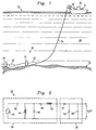
Fig. 1 illustrates an acquisition system located on a bottom surface of a body of water. -
Fig. 2 illustrates a block diagram of the front end of a geophone channel used in the acquisition system ofFig. 1 . -
Fig. 3 illustrates a block diagram of the front end of a hydrophone channel used in the acquisition system ofFig. 1 . -
Fig. 4 is flowchart illustrating a process of transforming the hydrophone response to a second order response. - Referring to
Fig. 1 , in a bottom cable survey method, an acquisition system, generally designated 20, hasmultiple hydrophones 22 andgeophones 24 grouped together at predetermined intervals. In one embodiment onehydrophone 22 is located in near proximity to one vertically alignedgeophone 24. In another embodiment onehydrophone 22 is located in near proximity to one vertically alignedgeophone 24 and two horizontally aligned geophones (not shown). Theacquisition system 20 is located at abottom 26 of a body ofwater 28 to measure seismic energy. Theacquisition system 20 is coupled to arecording unit 30 and aprocessing unit 31, located at asurface 32 of the body ofwater 28, through acable 34. Therecording unit 30 records hydro measurements taken by thehydrophone 22 and geomeasurements taken by thegeophone 24. Afilter 36 is present to correct the hydro measurements, as discussed in detail below. Each hydrophone/geophone group along thecable 34 represents a unique source of data collection. Accordingly, each group has a separate channel for passing data from the group to thefilter 36 and therecording unit 30. All data collected from thehydrophones 22 are coupled to thefilter 36. - Referring now to
Fig. 2 , an electrical model, generally designated 39, of thegeophone 24 includes asource 40, Vi (s), which is an electrical representation of the seismic energy measured by thegeophone 24, ageophone capacitance 42, aparallel geophone inductance 44, aparallel geophone resistance 46, aseries geophone resistance 48, and aseries geophone inductance 50. Thesource 40 produces electrical energy having a phase and an amplitude related to the velocity of the seismic energy. The output of thegeophone 24 is connected to an amplifier input through a pre-amplifier 52. The pre-amplifier 52 has a series pre-amplifierresistor 54, a parallel pre-amplifierresistor 56, and apre-amplifier capacitor 58. The geophone channel input is represented by the following equation derived using basic electrical network theory, such as Laplace transform theory, and omitted for clarity:
where N2 is a predetermined constant, s is the Laplacian variable, and D4, D3, D2, D1, and D0 are predetermined constants. - Referring now to
Fig. 3 , an electrical model, generally designated 62 of thehydrophone 22 has asource 64, Vi (s), which is an electrical representation of the seismic energy measured by thehydrophone 22, and ahydrophone capacitance 66. Thesource 64 produces electrical energy having a phase and an amplitude corresponding to the pressure caused by the seismic energy. The value of thecapacitance 66 in any givenhydrophone 22 changes with variations in temperature and with variations in depth. The value ofcapacitance 66 also varies from one hydrophone to the next. Therefore, the user determines the value of thecapacitance 66 at an operating temperature using a voltage driver (not shown) located in close proximity to thehydrophone 22 and a capacitance of known value. Furthermore, the user determines the value of thecapacitance 66 for eachhydrophone 22 because the response of thehydrophones 22 varies from hydrophone to hydrophone, even though eachhydrophone 22 is at substantially the same temperature when deployed on thebottom 26. The user injects a test signal (not shown) into the hydrophone to produce a first test data set. Then the user electrically disconnects thehydrophone 22 using a switch (not shown). Then the user injects the test signal into the group to produces a second test data set. The user determines the value of thecapacitance 66 by comparing the first test data set to the second test data set. Aprocessing unit 31 adjusts coefficients of thefilter 36 based on thecapacitance 66 value for each of thehydrophones 22. The output of thehydrophone 22 is coupled to atermination resistor 68 and thecorrection amplifier 36. Theresistor 68 and thecapacitance 66 establish the uncorrected low end frequency response of thehydrophone 22. The hydrophone channel input is represented by the following equation derived using basic electrical network theory, such as Laplace transform theory, which is omitted for clarity:
where Ch is the hydrophone capacitance, s is the Laplacian variable, and R2 is a predetermined constant. - The response of the
hydrophone 22 is corrected using a digital signal processing filter (DSPF). Thefilter 36 transforms the output of each of thehydrophones 22 to create a second order response, which appears to have originated from a geophone. Thefilter 36 is a bilinear transform of the following transfer function, which is derived by dividing equation (1) by equation (2):
- Using the transfer function of equation (3), the
filter 36 replaces the first order response with a second order response to give a phase and amplitude response that closely matches the response of a geophone. - Furthermore, the
filter 36 compensates for changes incapacitance 66 variations caused by temperature or depth change. - Referring now to
Fig. 4 , aprocess 100 is used for transforming a first order response of a hydrophone to a second order response. Atstep 102 the user determines thecapacitance 66 of thehydrophones 22,Fig. 3 . Atstep 104, theprocessing unit 31 establishes the filter coefficients for eachhydrophone 22 that is used in the transfer function that thefilter 36 applies to data produced by each of thehydrophones 22. Atstep 106 thefilter 36 transforms the measurements produced by each of thehydrophones 22 from a first order response to a second order response like that of a geophone. - In order to determine the
capacitance 66 for each of thehydrophones 22, theacquisition system 20 is located in the desired location, such as thebottom surface 26,Fig. 1 . Atstep 112 eachhydrophone 22 is excited using a predetermined voltage generated by the voltage driver. Atstep 114 the capacitance of each of thehydrophones 22 are measured. - In operation the user deploys the
acquisition system 20 on thebottom surface 26 of a body of water. The user can survey the formations located below thebottom surface 26 using theacquisition system 20. The user determines a first capacitance value of thehydrophone 22 at one temperature, such as the temperature at the surface of a body of water being surveyed. The user places thehydrophone 22 in a desired location, such as the bottom of the body ofwater 26 and determines a second capacitance value of thehydrophone 22 at this working temperature. The user generates a seismic signal. The seismic signal travels through the formation and is reflected by the boundaries in the formation. The reflected signal return and is recorded by theacquisition system 20. Thegeophones 24 produce geomeasurements based on velocity of the reflected seismic energy. The geomeasurements are stored in therecording unit 30. Thehydrophones 22 produce hydro measurements corresponding to the pressure caused by the seismic signal. The hydro measurements are processed using the transfer function set forth in equation (3) above. The processed hydro measurements are stored in therecording unit 30. The recorded data allows the user to later combine the geomeasurements and the hydro measurements to eliminate the unwanted reverberations and generate a seismic image of the formation. - In another embodiment of the present invention, the
filter 36 can be implemented with s-domain sub-filters executing on data from various sampling rates. Accordingly, the bilinear transform is performed on or applied to each of the s-domain sub-filters to produce a sub-filter appropriate to the sample rate at which the sub-filter executes. - Although illustrative embodiments have been shown and described, a wide range of modifications, changes and substitutions is contemplated in the foregoing disclosure.
Claims (9)
- A method of transforming a response of a hydrophone (22) excited by seismic energy as recorded by an acquisition system (20) having both a geophone (24) and the hydrophone (22) to a response of the geophone (24), the method characterized by :determining a response of the acquisition system (20) excited by a predetermined voltage with the hydrophone (22) electrically coupled to the acquisition system (20) to obtain a first data set;determining a response of the acquisition system (20) excited by the predetermined voltage with the hydrophone (22) electrically isolated from the acquisition system (20) to obtain a second data set;determining a capacitance of the hydrophone (22) from a comparison of the first test data set and the second test data set;producing a transfer function based on the determined capacitance;establishing a filter (36) based on a bilinear transform of the transfer function;applying the filter (36) to transform the response of the hydrophone (22) into a response similar to the response of the geophone
- The method of claim 1 wherein the transfer function is based on a ratio in a frequency domain of a response of the geophone and the response of the hydrophone.
- The method of claim 1 wherein the filter (36) is a digital filter.
- The method of claim 3 wherein the digital filter is implemented in a digital signal processor.
- The method of claim 1 wherein a portion of the filter (36) is a digital filter.
- The method of claim 5 wherein the digital filter is implemented in a digital signal processor.
- The method of claim 3 wherein the digital filter is split into at least two sub-filters, with at least one of the sub-filters executed on data at a higher sample rate than at least one of the other sub-filters.
- An apparatus for surveying a subsurface formation using seismic energy comprising:a processing unit (31) for generating a seismic image;a recording unit (30) coupled to the processing unit (31) for storing data and the seismic image;an acquisition unit (20) coupled to the processing unit (31) for measuring the response of the formation to the seismic energy;a plurality of hydrophones (22) coupled to the acquisition unit (20); anda plurality of geophones (24) coupled to the acquisition unit (20);the apparatus characterized by:a filter (36) coupled to the processing unit (31) for transforming a response of each of the plurality of hydrophones (22) into a response similar to a response of the plurality of geophones (24), the filter established by a bilinear transform of a transfer function based on a capacitance of the plurality of hydrophones (22), wherein the capacitance is determined from a comparison of a first test data set determined from a response of the acquisition system (20) excited by a predetermined voltage with the hydrophone (22) electrically coupled to the acquisition system (20) and a second test data set determined from a response of the acquisition system (20) excited by the predetermined voltage with the hydrophone (22) electrically isolated from the acquisition system (20).
- The apparatus of claim 8 wherein each of the plurality of hydrophones (22) has a unique transfer function due to physical characteristics of the plurality of hydrophones (22).
Applications Claiming Priority (3)
| Application Number | Priority Date | Filing Date | Title |
|---|---|---|---|
| US962125 | 1997-10-31 | ||
| US08/962,125 US6201764B1 (en) | 1997-10-31 | 1997-10-31 | Apparatus and method for correcting for capacitance variations in hydrophones |
| PCT/US1998/023011 WO1999023511A1 (en) | 1997-10-31 | 1998-10-29 | Apparatus and method for correcting for capacitance variations in hydrophones |
Publications (3)
| Publication Number | Publication Date |
|---|---|
| EP0958512A1 EP0958512A1 (en) | 1999-11-24 |
| EP0958512A4 EP0958512A4 (en) | 2008-05-28 |
| EP0958512B1 true EP0958512B1 (en) | 2011-11-23 |
Family
ID=25505450
Family Applications (1)
| Application Number | Title | Priority Date | Filing Date |
|---|---|---|---|
| EP98956347A Expired - Lifetime EP0958512B1 (en) | 1997-10-31 | 1998-10-29 | Apparatus and method for correcting for capacitance variations in hydrophones |
Country Status (5)
| Country | Link |
|---|---|
| US (1) | US6201764B1 (en) |
| EP (1) | EP0958512B1 (en) |
| AT (1) | ATE534922T1 (en) |
| AU (1) | AU1288999A (en) |
| WO (1) | WO1999023511A1 (en) |
Families Citing this family (15)
| Publication number | Priority date | Publication date | Assignee | Title |
|---|---|---|---|---|
| JP2000299922A (en) * | 1999-02-12 | 2000-10-24 | Yazaki Corp | Power supply control device and power supply control method |
| CN1120377C (en) * | 2000-04-26 | 2003-09-03 | 西安石油勘探仪器总厂 | Drawn submarine four-component integral earthquake data collecting unit |
| US7239577B2 (en) * | 2002-08-30 | 2007-07-03 | Pgs Americas, Inc. | Apparatus and methods for multicomponent marine geophysical data gathering |
| GB2415258B8 (en) * | 2002-08-30 | 2007-06-07 | Pgs Americas Inc | Method for multicomponent marine geophysical data gathering |
| US20110085417A1 (en) * | 2009-10-12 | 2011-04-14 | Daniel Ronnow | String of Sensor Assemblies Having a Seismic Sensor and Pressure Sensor |
| US8520469B2 (en) * | 2009-10-12 | 2013-08-27 | Westerngeco L.L.C. | Sensor assembly having a seismic sensor, pressure sensor, and processor to apply first and second digital filters |
| US12109429B2 (en) | 2015-07-28 | 2024-10-08 | Know Bio, Llc | Phototherapeutic light for treatment of pathogens |
| CN108136196B (en) | 2015-07-28 | 2020-07-17 | 诺欧生物有限责任公司 | System and method for phototherapy modulation of nitric oxide |
| US11986666B2 (en) | 2020-03-19 | 2024-05-21 | Know Bio, Llc | Illumination devices for inducing biological effects |
| US11147984B2 (en) | 2020-03-19 | 2021-10-19 | Know Bio, Llc | Illumination devices for inducing biological effects |
| US12011611B2 (en) | 2020-03-19 | 2024-06-18 | Know Bio, Llc | Illumination devices for inducing biological effects |
| US12447354B2 (en) | 2020-03-19 | 2025-10-21 | Know Bio, Llc | Illumination devices for inducing biological effects |
| US12347337B2 (en) | 2020-12-10 | 2025-07-01 | Know Bio, Llc | Enhanced testing and characterization techniques for phototherapeutic light treatments |
| US11654294B2 (en) | 2021-03-15 | 2023-05-23 | Know Bio, Llc | Intranasal illumination devices |
| US12115384B2 (en) | 2021-03-15 | 2024-10-15 | Know Bio, Llc | Devices and methods for illuminating tissue to induce biological effects |
Family Cites Families (5)
| Publication number | Priority date | Publication date | Assignee | Title |
|---|---|---|---|---|
| US4253164A (en) * | 1978-10-30 | 1981-02-24 | Western Geophysical Co. Of America | Multi-purpose seismic transducer |
| EG19158A (en) * | 1989-08-25 | 1996-02-29 | Halliburton Geophys Service | System for attenuation of water-column reverberation |
| US5235554A (en) * | 1991-03-11 | 1993-08-10 | Halliburton Geophysical Services, Inc. | Method for correcting impulse response differences of hydrophones and geophones as well as geophone coupling to the water-bottom in dual-sensor, bottom-cable seismic operations |
| US5163028A (en) * | 1991-09-27 | 1992-11-10 | Halliburton Geophysical Services, Inc. | Method for correcting impulse response differences of hydrophones and geophones as well as geophone coupling to the water-bottom in dual-sensor, bottom-cable seismic operations |
| US5408440A (en) * | 1993-03-19 | 1995-04-18 | Western Atlas International, Inc. | Hydrophone circuit with electrical characteristics of a geophone |
-
1997
- 1997-10-31 US US08/962,125 patent/US6201764B1/en not_active Expired - Lifetime
-
1998
- 1998-10-29 EP EP98956347A patent/EP0958512B1/en not_active Expired - Lifetime
- 1998-10-29 AU AU12889/99A patent/AU1288999A/en not_active Abandoned
- 1998-10-29 WO PCT/US1998/023011 patent/WO1999023511A1/en not_active Ceased
- 1998-10-29 AT AT98956347T patent/ATE534922T1/en active
Also Published As
| Publication number | Publication date |
|---|---|
| WO1999023511A1 (en) | 1999-05-14 |
| ATE534922T1 (en) | 2011-12-15 |
| EP0958512A1 (en) | 1999-11-24 |
| US6201764B1 (en) | 2001-03-13 |
| EP0958512A4 (en) | 2008-05-28 |
| AU1288999A (en) | 1999-05-24 |
Similar Documents
| Publication | Publication Date | Title |
|---|---|---|
| US5715213A (en) | High fidelity vibratory source seismic method using a plurality of vibrator sources | |
| EP1609002B1 (en) | Shaped high frequency vibratory source | |
| EP0824709B1 (en) | High fidelity vibratory source seismic method | |
| US6201764B1 (en) | Apparatus and method for correcting for capacitance variations in hydrophones | |
| CA2234938C (en) | High fidelity vibratory source seismic method for use in vertical seismic profile data gathering with a plurality of vibratory seismic energy sources | |
| CA2277119C (en) | Seismic data acquisition and processing using non-linear distortion in a groundforce signal | |
| RU2116657C1 (en) | Method for processing of seismic data in order to suppress multiple reflections | |
| EP0681193B1 (en) | Method of attenuating coherent noise in marine seismic data | |
| EP0861450B1 (en) | Plural vibrator single step inversion separation method | |
| EP0534648B1 (en) | Method of marine seismic exploration | |
| US4887244A (en) | Method for seismic trace interpolation using a forward and backward application of wave equation datuming | |
| Mordret et al. | Helmholtz tomography of ambient noise surface wave data to estimate Scholte wave phase velocity at Valhall Life of the Field | |
| EP0515188B1 (en) | Method in marine seismics of removing multiple data | |
| US8687463B2 (en) | Method for processing at least two sets of seismic data | |
| US5287328A (en) | Method for removing random source and receiver noise from seismic traces | |
| EP1068545B1 (en) | Ground roll attenuation method | |
| US4706225A (en) | Process for obtaining and processing seismic data measured at an exploratory well | |
| MXPA05002222A (en) | Method and apparatus for filtering irregularly sampled data. | |
| EP0288154B1 (en) | Method for estimating shear wave reflection data from acquired compressional wave reflection data | |
| NO315625B1 (en) | Method for marine seismic exploration using a hydrophone / geophone sensor pair | |
| EP0541265B1 (en) | Method of processing seismic data | |
| US4298966A (en) | Removal of surface layer anomaly effects | |
| US5638338A (en) | Seismic processing apparatus and method | |
| US4785196A (en) | Method and apparatus for converting seismic traces to synthetic well logs | |
| Stone | Dephasing seismic surveys |
Legal Events
| Date | Code | Title | Description |
|---|---|---|---|
| PUAI | Public reference made under article 153(3) epc to a published international application that has entered the european phase |
Free format text: ORIGINAL CODE: 0009012 |
|
| AK | Designated contracting states |
Kind code of ref document: A1 Designated state(s): AT BE CH CY DE DK ES FI FR GB GR IE IT LI LU MC NL PT SE |
|
| 17P | Request for examination filed |
Effective date: 19991108 |
|
| A4 | Supplementary search report drawn up and despatched |
Effective date: 20080428 |
|
| 17Q | First examination report despatched |
Effective date: 20080807 |
|
| RAP1 | Party data changed (applicant data changed or rights of an application transferred) |
Owner name: ION GEOPHYSICAL CORPORATION |
|
| GRAP | Despatch of communication of intention to grant a patent |
Free format text: ORIGINAL CODE: EPIDOSNIGR1 |
|
| GRAS | Grant fee paid |
Free format text: ORIGINAL CODE: EPIDOSNIGR3 |
|
| GRAA | (expected) grant |
Free format text: ORIGINAL CODE: 0009210 |
|
| AK | Designated contracting states |
Kind code of ref document: B1 Designated state(s): AT BE CH CY DE DK ES FI FR GB GR IE IT LI LU MC NL PT SE |
|
| REG | Reference to a national code |
Ref country code: GB Ref legal event code: FG4D |
|
| REG | Reference to a national code |
Ref country code: CH Ref legal event code: EP |
|
| REG | Reference to a national code |
Ref country code: IE Ref legal event code: FG4D |
|
| REG | Reference to a national code |
Ref country code: NL Ref legal event code: T3 |
|
| REG | Reference to a national code |
Ref country code: DE Ref legal event code: R096 Ref document number: 69842508 Country of ref document: DE Effective date: 20120126 |
|
| PG25 | Lapsed in a contracting state [announced via postgrant information from national office to epo] |
Ref country code: SE Free format text: LAPSE BECAUSE OF FAILURE TO SUBMIT A TRANSLATION OF THE DESCRIPTION OR TO PAY THE FEE WITHIN THE PRESCRIBED TIME-LIMIT Effective date: 20111123 Ref country code: GR Free format text: LAPSE BECAUSE OF FAILURE TO SUBMIT A TRANSLATION OF THE DESCRIPTION OR TO PAY THE FEE WITHIN THE PRESCRIBED TIME-LIMIT Effective date: 20120224 Ref country code: BE Free format text: LAPSE BECAUSE OF FAILURE TO SUBMIT A TRANSLATION OF THE DESCRIPTION OR TO PAY THE FEE WITHIN THE PRESCRIBED TIME-LIMIT Effective date: 20111123 Ref country code: PT Free format text: LAPSE BECAUSE OF FAILURE TO SUBMIT A TRANSLATION OF THE DESCRIPTION OR TO PAY THE FEE WITHIN THE PRESCRIBED TIME-LIMIT Effective date: 20120323 |
|
| PG25 | Lapsed in a contracting state [announced via postgrant information from national office to epo] |
Ref country code: CY Free format text: LAPSE BECAUSE OF FAILURE TO SUBMIT A TRANSLATION OF THE DESCRIPTION OR TO PAY THE FEE WITHIN THE PRESCRIBED TIME-LIMIT Effective date: 20111123 |
|
| PG25 | Lapsed in a contracting state [announced via postgrant information from national office to epo] |
Ref country code: DK Free format text: LAPSE BECAUSE OF FAILURE TO SUBMIT A TRANSLATION OF THE DESCRIPTION OR TO PAY THE FEE WITHIN THE PRESCRIBED TIME-LIMIT Effective date: 20111123 |
|
| PG25 | Lapsed in a contracting state [announced via postgrant information from national office to epo] |
Ref country code: IT Free format text: LAPSE BECAUSE OF FAILURE TO SUBMIT A TRANSLATION OF THE DESCRIPTION OR TO PAY THE FEE WITHIN THE PRESCRIBED TIME-LIMIT Effective date: 20111123 |
|
| REG | Reference to a national code |
Ref country code: AT Ref legal event code: MK05 Ref document number: 534922 Country of ref document: AT Kind code of ref document: T Effective date: 20111123 |
|
| PLBE | No opposition filed within time limit |
Free format text: ORIGINAL CODE: 0009261 |
|
| STAA | Information on the status of an ep patent application or granted ep patent |
Free format text: STATUS: NO OPPOSITION FILED WITHIN TIME LIMIT |
|
| 26N | No opposition filed |
Effective date: 20120824 |
|
| REG | Reference to a national code |
Ref country code: DE Ref legal event code: R097 Ref document number: 69842508 Country of ref document: DE Effective date: 20120824 |
|
| PG25 | Lapsed in a contracting state [announced via postgrant information from national office to epo] |
Ref country code: AT Free format text: LAPSE BECAUSE OF FAILURE TO SUBMIT A TRANSLATION OF THE DESCRIPTION OR TO PAY THE FEE WITHIN THE PRESCRIBED TIME-LIMIT Effective date: 20111123 |
|
| PG25 | Lapsed in a contracting state [announced via postgrant information from national office to epo] |
Ref country code: ES Free format text: LAPSE BECAUSE OF FAILURE TO SUBMIT A TRANSLATION OF THE DESCRIPTION OR TO PAY THE FEE WITHIN THE PRESCRIBED TIME-LIMIT Effective date: 20120305 |
|
| PG25 | Lapsed in a contracting state [announced via postgrant information from national office to epo] |
Ref country code: MC Free format text: LAPSE BECAUSE OF NON-PAYMENT OF DUE FEES Effective date: 20121031 |
|
| REG | Reference to a national code |
Ref country code: CH Ref legal event code: PL |
|
| PG25 | Lapsed in a contracting state [announced via postgrant information from national office to epo] |
Ref country code: FI Free format text: LAPSE BECAUSE OF FAILURE TO SUBMIT A TRANSLATION OF THE DESCRIPTION OR TO PAY THE FEE WITHIN THE PRESCRIBED TIME-LIMIT Effective date: 20111123 |
|
| PG25 | Lapsed in a contracting state [announced via postgrant information from national office to epo] |
Ref country code: LI Free format text: LAPSE BECAUSE OF NON-PAYMENT OF DUE FEES Effective date: 20121031 Ref country code: CH Free format text: LAPSE BECAUSE OF NON-PAYMENT OF DUE FEES Effective date: 20121031 Ref country code: DE Free format text: LAPSE BECAUSE OF NON-PAYMENT OF DUE FEES Effective date: 20130501 |
|
| REG | Reference to a national code |
Ref country code: IE Ref legal event code: MM4A |
|
| REG | Reference to a national code |
Ref country code: DE Ref legal event code: R119 Ref document number: 69842508 Country of ref document: DE Effective date: 20130501 |
|
| PG25 | Lapsed in a contracting state [announced via postgrant information from national office to epo] |
Ref country code: IE Free format text: LAPSE BECAUSE OF NON-PAYMENT OF DUE FEES Effective date: 20121029 |
|
| PG25 | Lapsed in a contracting state [announced via postgrant information from national office to epo] |
Ref country code: LU Free format text: LAPSE BECAUSE OF NON-PAYMENT OF DUE FEES Effective date: 20121029 |
|
| REG | Reference to a national code |
Ref country code: FR Ref legal event code: PLFP Year of fee payment: 19 |
|
| REG | Reference to a national code |
Ref country code: FR Ref legal event code: PLFP Year of fee payment: 20 |
|
| PGFP | Annual fee paid to national office [announced via postgrant information from national office to epo] |
Ref country code: FR Payment date: 20170918 Year of fee payment: 20 |
|
| PGFP | Annual fee paid to national office [announced via postgrant information from national office to epo] |
Ref country code: NL Payment date: 20171016 Year of fee payment: 20 Ref country code: GB Payment date: 20171025 Year of fee payment: 20 |
|
| REG | Reference to a national code |
Ref country code: NL Ref legal event code: MK Effective date: 20181028 |
|
| REG | Reference to a national code |
Ref country code: GB Ref legal event code: PE20 Expiry date: 20181028 |
|
| PG25 | Lapsed in a contracting state [announced via postgrant information from national office to epo] |
Ref country code: GB Free format text: LAPSE BECAUSE OF EXPIRATION OF PROTECTION Effective date: 20181028 |