EP0958082B1 - Boring bar - Google Patents
Boring bar Download PDFInfo
- Publication number
- EP0958082B1 EP0958082B1 EP97932109A EP97932109A EP0958082B1 EP 0958082 B1 EP0958082 B1 EP 0958082B1 EP 97932109 A EP97932109 A EP 97932109A EP 97932109 A EP97932109 A EP 97932109A EP 0958082 B1 EP0958082 B1 EP 0958082B1
- Authority
- EP
- European Patent Office
- Prior art keywords
- adhesive
- shaft portion
- bar
- boring bar
- boring
- Prior art date
- Legal status (The legal status is an assumption and is not a legal conclusion. Google has not performed a legal analysis and makes no representation as to the accuracy of the status listed.)
- Expired - Lifetime
Links
- 239000000853 adhesive Substances 0.000 claims description 52
- 230000001070 adhesive effect Effects 0.000 claims description 52
- 238000013016 damping Methods 0.000 claims description 15
- 239000000463 material Substances 0.000 claims description 8
- NIXOWILDQLNWCW-UHFFFAOYSA-M Acrylate Chemical compound [O-]C(=O)C=C NIXOWILDQLNWCW-UHFFFAOYSA-M 0.000 claims description 4
- 229920006332 epoxy adhesive Polymers 0.000 claims description 4
- ISWSIDIOOBJBQZ-UHFFFAOYSA-N Phenol Chemical compound OC1=CC=CC=C1 ISWSIDIOOBJBQZ-UHFFFAOYSA-N 0.000 claims description 3
- 238000004519 manufacturing process Methods 0.000 claims description 3
- FYYHWMGAXLPEAU-UHFFFAOYSA-N Magnesium Chemical compound [Mg] FYYHWMGAXLPEAU-UHFFFAOYSA-N 0.000 claims description 2
- 229910045601 alloy Inorganic materials 0.000 claims description 2
- 239000000956 alloy Substances 0.000 claims description 2
- 229910052782 aluminium Inorganic materials 0.000 claims description 2
- XAGFODPZIPBFFR-UHFFFAOYSA-N aluminium Chemical compound [Al] XAGFODPZIPBFFR-UHFFFAOYSA-N 0.000 claims description 2
- 229910052749 magnesium Inorganic materials 0.000 claims description 2
- 239000011777 magnesium Substances 0.000 claims description 2
- 238000000034 method Methods 0.000 claims description 2
- 229920000728 polyester Polymers 0.000 claims description 2
- 125000000391 vinyl group Chemical group [H]C([*])=C([H])[H] 0.000 claims description 2
- 229920002554 vinyl polymer Polymers 0.000 claims description 2
- 238000004026 adhesive bonding Methods 0.000 claims 1
- 239000000203 mixture Substances 0.000 claims 1
- 239000004814 polyurethane Substances 0.000 claims 1
- 229920002635 polyurethane Polymers 0.000 claims 1
- 238000005520 cutting process Methods 0.000 description 8
- 230000000694 effects Effects 0.000 description 4
- 229920001971 elastomer Polymers 0.000 description 4
- 239000007787 solid Substances 0.000 description 3
- 229910000639 Spring steel Inorganic materials 0.000 description 2
- 238000010276 construction Methods 0.000 description 2
- 238000003754 machining Methods 0.000 description 2
- 125000000951 phenoxy group Chemical group [H]C1=C([H])C([H])=C(O*)C([H])=C1[H] 0.000 description 2
- 229920001084 poly(chloroprene) Polymers 0.000 description 2
- 244000043261 Hevea brasiliensis Species 0.000 description 1
- 229910000997 High-speed steel Inorganic materials 0.000 description 1
- 239000004952 Polyamide Substances 0.000 description 1
- 229910000831 Steel Inorganic materials 0.000 description 1
- 229910001315 Tool steel Inorganic materials 0.000 description 1
- -1 acryl Chemical group 0.000 description 1
- 239000003245 coal Substances 0.000 description 1
- 230000000052 comparative effect Effects 0.000 description 1
- 239000002173 cutting fluid Substances 0.000 description 1
- 238000009661 fatigue test Methods 0.000 description 1
- 239000000835 fiber Substances 0.000 description 1
- 229910052751 metal Inorganic materials 0.000 description 1
- 239000002184 metal Substances 0.000 description 1
- 150000002739 metals Chemical class 0.000 description 1
- 229920003052 natural elastomer Polymers 0.000 description 1
- 229920001194 natural rubber Polymers 0.000 description 1
- 229920002647 polyamide Polymers 0.000 description 1
- 238000002360 preparation method Methods 0.000 description 1
- 239000012858 resilient material Substances 0.000 description 1
- 238000010008 shearing Methods 0.000 description 1
- 239000010959 steel Substances 0.000 description 1
- 229920002994 synthetic fiber Polymers 0.000 description 1
- 238000012360 testing method Methods 0.000 description 1
- 238000001029 thermal curing Methods 0.000 description 1
- 230000003313 weakening effect Effects 0.000 description 1
Images

Classifications
-
- B—PERFORMING OPERATIONS; TRANSPORTING
- B23—MACHINE TOOLS; METAL-WORKING NOT OTHERWISE PROVIDED FOR
- B23B—TURNING; BORING
- B23B27/00—Tools for turning or boring machines; Tools of a similar kind in general; Accessories therefor
- B23B27/007—Tools for turning or boring machines; Tools of a similar kind in general; Accessories therefor for internal turning
-
- B—PERFORMING OPERATIONS; TRANSPORTING
- B23—MACHINE TOOLS; METAL-WORKING NOT OTHERWISE PROVIDED FOR
- B23B—TURNING; BORING
- B23B29/00—Holders for non-rotary cutting tools; Boring bars or boring heads; Accessories for tool holders
- B23B29/02—Boring bars
- B23B29/022—Boring bars with vibration reducing means
-
- Y—GENERAL TAGGING OF NEW TECHNOLOGICAL DEVELOPMENTS; GENERAL TAGGING OF CROSS-SECTIONAL TECHNOLOGIES SPANNING OVER SEVERAL SECTIONS OF THE IPC; TECHNICAL SUBJECTS COVERED BY FORMER USPC CROSS-REFERENCE ART COLLECTIONS [XRACs] AND DIGESTS
- Y10—TECHNICAL SUBJECTS COVERED BY FORMER USPC
- Y10T—TECHNICAL SUBJECTS COVERED BY FORMER US CLASSIFICATION
- Y10T407/00—Cutters, for shaping
- Y10T407/22—Cutters, for shaping including holder having seat for inserted tool
-
- Y—GENERAL TAGGING OF NEW TECHNOLOGICAL DEVELOPMENTS; GENERAL TAGGING OF CROSS-SECTIONAL TECHNOLOGIES SPANNING OVER SEVERAL SECTIONS OF THE IPC; TECHNICAL SUBJECTS COVERED BY FORMER USPC CROSS-REFERENCE ART COLLECTIONS [XRACs] AND DIGESTS
- Y10—TECHNICAL SUBJECTS COVERED BY FORMER USPC
- Y10T—TECHNICAL SUBJECTS COVERED BY FORMER US CLASSIFICATION
- Y10T407/00—Cutters, for shaping
- Y10T407/22—Cutters, for shaping including holder having seat for inserted tool
- Y10T407/2272—Cutters, for shaping including holder having seat for inserted tool with separate means to fasten tool to holder
-
- Y—GENERAL TAGGING OF NEW TECHNOLOGICAL DEVELOPMENTS; GENERAL TAGGING OF CROSS-SECTIONAL TECHNOLOGIES SPANNING OVER SEVERAL SECTIONS OF THE IPC; TECHNICAL SUBJECTS COVERED BY FORMER USPC CROSS-REFERENCE ART COLLECTIONS [XRACs] AND DIGESTS
- Y10—TECHNICAL SUBJECTS COVERED BY FORMER USPC
- Y10T—TECHNICAL SUBJECTS COVERED BY FORMER US CLASSIFICATION
- Y10T407/00—Cutters, for shaping
- Y10T407/26—Cutters, for shaping comprising cutting edge bonded to tool shank
-
- Y—GENERAL TAGGING OF NEW TECHNOLOGICAL DEVELOPMENTS; GENERAL TAGGING OF CROSS-SECTIONAL TECHNOLOGIES SPANNING OVER SEVERAL SECTIONS OF THE IPC; TECHNICAL SUBJECTS COVERED BY FORMER USPC CROSS-REFERENCE ART COLLECTIONS [XRACs] AND DIGESTS
- Y10—TECHNICAL SUBJECTS COVERED BY FORMER USPC
- Y10T—TECHNICAL SUBJECTS COVERED BY FORMER US CLASSIFICATION
- Y10T407/00—Cutters, for shaping
- Y10T407/27—Cutters, for shaping comprising tool of specific chemical composition
-
- Y—GENERAL TAGGING OF NEW TECHNOLOGICAL DEVELOPMENTS; GENERAL TAGGING OF CROSS-SECTIONAL TECHNOLOGIES SPANNING OVER SEVERAL SECTIONS OF THE IPC; TECHNICAL SUBJECTS COVERED BY FORMER USPC CROSS-REFERENCE ART COLLECTIONS [XRACs] AND DIGESTS
- Y10—TECHNICAL SUBJECTS COVERED BY FORMER USPC
- Y10T—TECHNICAL SUBJECTS COVERED BY FORMER US CLASSIFICATION
- Y10T408/00—Cutting by use of rotating axially moving tool
- Y10T408/78—Tool of specific diverse material
Definitions
- the present invention relates to a boring bar comprising a shaft portion and a bar head according to claim 1 see e.g. DE-A 2 329 234, a process for the production of a boring bar according to claim 6, and the use of such a boring bar for the damping of vibrations at internal turning.
- Turning operations can be divided into those for external turning and those for inner turning, the latter normally called internal turning.
- external turning operations relate to turning on an external rotating surface of a workpiece
- internal turning refers to turning on an inner rotating surface.
- a special case of external turning is face turning.
- the overhang of the tool is not influenced by the length of the workpiece since external rotating surfaces usually are exposed and freely accessible.
- dimensions of tool holders may be chosen so that they resist the forces och stresses that arise.
- the choice of tool is restricted by the appearance of the workpiece, since this turning operation is usually applied in pre-drilled holes or holes in cast, forged or extruded elements.
- this turning operation is usually applied in pre-drilled holes or holes in cast, forged or extruded elements.
- a long boring bar with a long overhang is required, which of course increases the risk of deflection and vibrations, which in turn results in a worse surface smoothness and disturbing noise. This problem is accentuated by the fact that internal turning operations are mainly used for applications with high demands on dimension tolerances and surface smoothness.
- a damping arrangement for inter alia boring bars, which comprises a damping portion being arranged in an axial boring in the boring bar and being coupled to the same via one or several springing elements in the form of, e.g., sheets or circumferential rings of a resilient material such as rubber. Possibly, a fluidum may be introduced into the space between the damping portion and the boring, in order to contribute to the damping effect.
- this construction certainly reduces vibrations, it is complicated and space-demanding.
- a primary object of the present invention is to provide a boring bar with a reduced tendency for vibrations.
- a second object of the present invention is to make possible longer overhangs without thereby increasing the tendency for vibrations.
- Still another object of the present invention is to minimize the risk of vibrations in boring bars with the simplest possible construction.
- DE-A-1 552 450 discloses how an adhesive may be used for the fastening of cutting inserts of an highly alloyed steel or high speed steel in a holder, and also how the operative top portion of a reamer may be adhered to a shaft.
- these tools are not at all constructed for vibration damping purposes, but only for simplifying the replacement of operative cutting parts.
- boring bars divided into two parts are previously known, with a rear shaft portion and a front bar head, which is then screwed onto the shaft portion.
- Such a screw joint is rigid and does not allow any vibration damping effects at all.
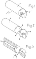
- a boring bar 1 is generally shown comprising a shaft portion 2 and a bar head 3.
- the rear part of the shaft is introduced into a holder in a way known per se , whereafter the necessary clamping force is obtained by a screw joint or by a hydraulic bushing.
- the shaft portion may be formed in a number of different ways, depending on which properties are desired and is not an essential feature of the invention.
- a suitable cutting insert 4 of a hard material, such as cemented carbide.
- the cutting insert is fastened in its insert seat by a locking screw, a clamp or similar.
- both may be produced of tool steel or spring steel, such as SS 2230.
- the bar head may also be made of a lighter material, such as aluminum or magnesium, or an alloy based on one or both of these two metals.
- the shaft portion may also be made of a lighter material.
- the shaft portion may be made of a coal fibre reinforced synthetic material.
- the shaft portion and the bar head are separate from each other, whereby it may be seen how the shaft portion has a substantially conical recess 5 and the bar head a substantially conical protrusion 6, the latter being provided to fit into the conical recess 5.
- the facing surfaces of the part 6 and the recess 5 are fixed to each other by an adhesive joint.
- the apex angle ⁇ of the adhesive joint is suitably between 2 and 50°, preferably between 5 and 30°.
- the joint length d is suitably between 10 and 200 mm, preferably between 25 and 120 mm.
- the shaft portion, and to some extent also the bar head may be hollow, suitably in the form of a central boring 7 and 7', respectively.
- This also contributes to lowering the total weight of the bar, at the expense of a negligibly small weakening.
- the diameter of the cavity may either be substantially constant or vary in axial direction. This makes it possible to alter the natural frequency and deflection of the bar in comparison with a solid bar.
- the diameter of the boring 7 may either increase or decrease in the direction of the bar head.
- the central cavity 7, 7' may be used for transporting any possible cutting fluid to the proximity of the operative cutting point (not shown).
- FIG. 1 The conical adhesive joint according to figures 1 to 3 constitutes a preferred embodiment; however not the sole one.
- figures 4 and 5 illustrate another embodiment, according to which the outer and inner cones have been replaced by a wedge-like boundary surface.
- the wedge shape is suitably radially uniform and has an apex angle ⁇ which corresponds to the angle ⁇ , i.e. ⁇ is suitably between 4 and 100°, preferably between 10 and 60°.
- the joint length corresponds to d in figure 3.
- this boring bar is solid, but it may also be formed with a central cavity, in the same way as the one shown in figures 1 to 3.
- a plurality of adhesive types have been found suitable för the present invention .
- advantageously adhesive types like epoxy adhesive, acrylate adhesive, polyuretane adhesives, phenol/vinyl adhesive, nitril adhesive, adhesives of natural and /or chloroprene-rubber, phenol/nitril adhesive, acrylalte rubber adhesive, polyamide adhesive or polyester adhesive, and possibly also phenoxy adhesive.
- These may be of the one-component or two-component type and may be used with or without thermal curing and a primer. Suitably, they are anaerobic.
- An example of a suitable type of epoxy adhesives is disclosed in DE-A-1 107 400.
- An example of a suitable acrylate adhesive is Araldit AV 118 (reg.
- a suitable adhesive joint thickness for the conical parts 5 and 6 may be between 0,05 and 0,8 mm, preferably between 0,1 and 0,5 mm. Surprisingly, it has also been demonstrated that in principle, the adhesive joint becomes equally strong also when the joint surfaces are black-oxidized or "jetalized".
- the shaft portion may be shaped in accordance with figure 6.
- the same may comprise an outer, tube- or sleeve-like part 9, which encloses a core 10 that is concentric with said part 9.
- This core may either consist of a massive bar or have a centrical boring 11.
- a second adhesive joint 12 which functions in a vibration damping way.
- the thickness of this adhesive joint may suitably be between 0,05 and 1,5 mm and may consist of the above mentioned adhesive types, suitably such a one that has a larger toughness and a greater capability of taking up energy.
- the sleeve part and the core may very well consist of different materials.
- acrylate adhesives, epoxy adhesives and phenoxy adhesives are particularly useful for the joint to the bar head, while for an optimal damping, nitril rubber adhesives, acryl rubber adhesives, chloroprene rubber adhesives and natural rubber adhesives are suitable for the shaft portion. If one in first hand does not want to have a vibration damping bar, but a bar with as little deflection as possible, one can use a harder material and a stronger adhesive also in the shaft portion.
- Comparative tests were performed between solid bars of 25 mm in diameter of spring steel, on one hand integrally in one sole piece and on the other hand with a conical adhesive joint according to the invention.
- the joint surfaces were in the form of cones with an angle ⁇ of 12°.
- the used adhesive type was Araldit AV 118 (reg. trademark) and the thickness of the adhesive joint was ⁇ 0,2 mm. A considerably improved damping was obtained.
- the useful life was extremely good: all bars resisted > 2 ⁇ 10 6 load cycles of 3,4 kN ⁇ 0,34 kN in a fatigue testing machine.
- the adhesive joint can resist a maximal load of at least 6,0 kN at the cutting point, which is a considerably higher load degree than the one that arises at normal machining.
Landscapes
- Engineering & Computer Science (AREA)
- Mechanical Engineering (AREA)
- Cutting Tools, Boring Holders, And Turrets (AREA)
- Earth Drilling (AREA)
- Processing Of Stones Or Stones Resemblance Materials (AREA)
- Adhesives Or Adhesive Processes (AREA)
- Vibration Prevention Devices (AREA)
Description
Claims (7)
- Boring bar comprising a shaft portion (2) and a bar head (3), characterized in that the shaft portion and the bar head are joined by gluing, the adhesive joint is between 0,05 and 1,5 mm thick and the bar head is manufactured in lighter material than the shaft part.
- Boring bar according to claim 1, characterized in that the shaft portion (2) in its front end has a conical recess (5) and the bar head at its rear end has a conically protruding part (6), the adhesive joint being between said two conical parts.
- Boring bar according to claim 1 or 2, characterized in that the shaft portion comprises a substantially cylindrical core (10) and a sleeve- or tube-like part (9) located outside said core, these two parts being joined by an adhesive joint.
- Boring bar according to claim 1, 2 or 3, characterized in that the adhesive is an epoxy adhesive, an acrylate adhesive, a polyurethane adhesive, a phenol/vinyl adhesive or a polyester adhesive, or chemically compatible mixtures of two or more of these.
- Boring bar according to any of the preceding claims, characterized in that the bar head (3) is made of aluminum or magnesium, or an alloy based on one or both of these.
- Process for the production of a boring bar according to any of claims 1-5 comprising a shaft portion (2) and a bar head (3), characterized in that the bar head is glued on the shaft portion, the adhesive joint is between 0,05 and 1,5 mm thick and the bar head is manufactured in lighter material than the shaft part.
- Use of a boring bar according to any of claims 1 to 5 for the damping of vibrations during internal turning.
Applications Claiming Priority (3)
| Application Number | Priority Date | Filing Date | Title |
|---|---|---|---|
| SE9602727A SE511395C2 (en) | 1996-07-08 | 1996-07-08 | Lathe boom, method of manufacturing a lathe boom and use of the same |
| SE9602727 | 1996-07-08 | ||
| PCT/SE1997/001232 WO1998001250A1 (en) | 1996-07-08 | 1997-07-07 | Boring bar |
Publications (3)
| Publication Number | Publication Date |
|---|---|
| EP0958082A1 EP0958082A1 (en) | 1999-11-24 |
| EP0958082B1 true EP0958082B1 (en) | 2002-09-18 |
| EP0958082B2 EP0958082B2 (en) | 2007-06-13 |
Family
ID=20403350
Family Applications (1)
| Application Number | Title | Priority Date | Filing Date |
|---|---|---|---|
| EP97932109A Expired - Lifetime EP0958082B2 (en) | 1996-07-08 | 1997-07-07 | Boring bar |
Country Status (6)
| Country | Link |
|---|---|
| US (1) | US6076999A (en) |
| EP (1) | EP0958082B2 (en) |
| JP (1) | JP2001505133A (en) |
| DE (1) | DE69715673T3 (en) |
| SE (1) | SE511395C2 (en) |
| WO (1) | WO1998001250A1 (en) |
Families Citing this family (44)
| Publication number | Priority date | Publication date | Assignee | Title |
|---|---|---|---|---|
| US7749215B1 (en) * | 1998-02-05 | 2010-07-06 | Biosense, Inc. | Intracardiac cell delivery and cell transplantation |
| JP2001062612A (en) * | 1999-08-23 | 2001-03-13 | Tasada Kosakusho:Kk | Hole cutting tool |
| JP4313482B2 (en) * | 1999-09-30 | 2009-08-12 | 京セラ株式会社 | Cutting tools |
| JP2002113603A (en) * | 2000-10-06 | 2002-04-16 | Honda Motor Co Ltd | Vibration controlled cutting tool |
| SE522081C2 (en) * | 2000-12-06 | 2004-01-13 | Sandvik Ab | Tools for machining in metallic materials |
| NO319690B1 (en) * | 2001-01-23 | 2005-09-05 | Teeness Asa | Cutter head for machine tools |
| CN1533314A (en) * | 2001-07-23 | 2004-09-29 | 韩国科学技术院 | High hardness synthetic blade |
| KR100441386B1 (en) * | 2001-07-23 | 2004-07-23 | 비젼이노텍(주) | High stiffness composite line boring bar and manufacturing the same |
| KR100441251B1 (en) * | 2002-07-09 | 2004-07-21 | 비젼이노텍(주) | Stiffness gradient tool bar for processing and its manufacturing method |
| JP2003117703A (en) * | 2001-10-11 | 2003-04-23 | Ngk Spark Plug Co Ltd | Shanks and cutting tools |
| KR100548964B1 (en) * | 2003-09-23 | 2006-02-03 | 비젼이노텍(주) | Composite tool bars for bite joining |
| SE528470C2 (en) | 2004-02-03 | 2006-11-21 | Mircona Ab | Vibration-damped tool holder with viscoelastic damping material |
| US20050169715A1 (en) * | 2004-02-04 | 2005-08-04 | Valenite Llc | Tool holder and method of making |
| SE528247C2 (en) * | 2004-05-07 | 2006-10-03 | Mircona Ab | Vibration dampened tool holder |
| US20060024140A1 (en) * | 2004-07-30 | 2006-02-02 | Wolff Edward C | Removable tap chasers and tap systems including the same |
| KR100683943B1 (en) * | 2004-10-29 | 2007-02-15 | 비젼이노텍(주) | Precision Machining Tool Using Composite Material |
| US8637127B2 (en) | 2005-06-27 | 2014-01-28 | Kennametal Inc. | Composite article with coolant channels and tool fabrication method |
| US7687156B2 (en) | 2005-08-18 | 2010-03-30 | Tdy Industries, Inc. | Composite cutting inserts and methods of making the same |
| DE102006012382A1 (en) * | 2006-03-17 | 2007-09-20 | Kennametal Inc. | Turning tool, in particular drilling tool and tool head for a turning tool |
| JP2009535536A (en) | 2006-04-27 | 2009-10-01 | ティーディーワイ・インダストリーズ・インコーポレーテッド | Modular fixed cutter boring bit, modular fixed cutter boring bit body and related method |
| WO2008051588A2 (en) | 2006-10-25 | 2008-05-02 | Tdy Industries, Inc. | Articles having improved resistance to thermal cracking |
| US20080298913A1 (en) * | 2007-06-04 | 2008-12-04 | The Boeing Company | Increased Process Damping Via Mass Reduction for High Performance Milling |
| US8529173B2 (en) | 2008-01-22 | 2013-09-10 | Valenite, Llc | Method to align characteristic frequency of material removal tool and rotation speed of spindle of machine tool and material removal tool so aligned |
| US8790439B2 (en) | 2008-06-02 | 2014-07-29 | Kennametal Inc. | Composite sintered powder metal articles |
| CN102112642B (en) | 2008-06-02 | 2013-11-06 | Tdy工业有限责任公司 | Cemented carbide-metallic alloy composites |
| US8025112B2 (en) | 2008-08-22 | 2011-09-27 | Tdy Industries, Inc. | Earth-boring bits and other parts including cemented carbide |
| US8272816B2 (en) | 2009-05-12 | 2012-09-25 | TDY Industries, LLC | Composite cemented carbide rotary cutting tools and rotary cutting tool blanks |
| SE533786C2 (en) * | 2009-05-25 | 2011-01-11 | Sandvik Intellectual Property | Apparatus and method for milling material |
| EP2435202B1 (en) * | 2009-05-26 | 2013-08-14 | GKN Aerospace Sweden AB | A holder for a cutting tool, a cutting tool and a cutting insert |
| US8308096B2 (en) | 2009-07-14 | 2012-11-13 | TDY Industries, LLC | Reinforced roll and method of making same |
| JP5383421B2 (en) * | 2009-10-16 | 2014-01-08 | 三菱重工業株式会社 | Boring tool |
| US9643236B2 (en) | 2009-11-11 | 2017-05-09 | Landis Solutions Llc | Thread rolling die and method of making same |
| SE535054C2 (en) * | 2010-03-17 | 2012-03-27 | Sandvik Intellectual Property | Milling tools for cutting machining with damping means arranged in the tool body |
| DE102010015229B4 (en) | 2010-04-15 | 2014-09-11 | Leichtbau-Zentrum Sachsen Gmbh | A cutting tool for machine boring or turning with an elongate shaft and method of making the same |
| DE102010036874A1 (en) * | 2010-08-05 | 2012-02-23 | Gühring Ohg | Cutting tool and method for its production |
| EP2457678B1 (en) * | 2010-11-29 | 2016-03-30 | Techspace Aero S.A. | Bi-material one-piece cutting tool |
| KR101201144B1 (en) * | 2010-12-28 | 2012-11-13 | 한국기초과학지원연구원 | Having a long axis of the structure vibration suppression bytes |
| US8800848B2 (en) | 2011-08-31 | 2014-08-12 | Kennametal Inc. | Methods of forming wear resistant layers on metallic surfaces |
| US9016406B2 (en) | 2011-09-22 | 2015-04-28 | Kennametal Inc. | Cutting inserts for earth-boring bits |
| CN102672217A (en) * | 2012-05-24 | 2012-09-19 | 山东大学 | Coating damping cutter rod and damping testing method thereof |
| DE102013101854A1 (en) * | 2013-02-05 | 2014-08-07 | Franz Haimer Maschinenbau Kg | Chuck with vibration reduction |
| SE540533C2 (en) * | 2016-02-12 | 2018-09-25 | Plasmatrix Mat Ab | Cutting tool assembly with controlled resilience using hyperelastic materials |
| WO2020230569A1 (en) * | 2019-05-15 | 2020-11-19 | 住友電工ハードメタル株式会社 | Boring holder and turning tool |
| JP7564881B2 (en) * | 2020-03-31 | 2024-10-09 | マク アクティエボラーグ | Tool holder for a tool assembly and tool assembly comprising said tool holder |
Family Cites Families (20)
| Publication number | Priority date | Publication date | Assignee | Title |
|---|---|---|---|---|
| DE947659C (en) * | 1953-05-09 | 1956-08-23 | Karl Hertel | Carbide cutting body |
| DE1403000A1 (en) * | 1960-10-22 | 1968-11-21 | Warner Swasey Co | Carbide tool for turning |
| DE1552450A1 (en) * | 1966-03-12 | 1970-01-08 | Erwin Stuber | Cutting tools such as turning tools, milling cutters, reamers and the like. |
| DE1920598A1 (en) * | 1969-04-23 | 1970-11-05 | Goetzewerke | Device for damping torsional vibrations in self-supporting machine parts, in particular tool carriers |
| JPS5023164Y1 (en) * | 1969-05-10 | 1975-07-12 | ||
| US3751176A (en) * | 1970-12-21 | 1973-08-07 | Von Hollen Tool Co Inc | Composite bit |
| NO128725B (en) * | 1972-01-21 | 1974-01-02 | Trondhjems Nagle Spigerfab | |
| JPS54149095A (en) * | 1978-05-16 | 1979-11-21 | Toshiba Corp | Boring holder |
| JPS588505U (en) * | 1981-07-03 | 1983-01-20 | 住友電気工業株式会社 | boring cutter |
| DE3314349A1 (en) * | 1983-04-20 | 1984-10-25 | Gühring, Gottlieb, 7470 Albstadt | Bore-finishing tool |
| DE3331907A1 (en) * | 1983-09-03 | 1985-03-21 | Otto 2050 Hamburg Lehmann | TURNING CHISEL |
| JPS6138804A (en) * | 1984-07-31 | 1986-02-24 | Mitsubishi Heavy Ind Ltd | Tipped tool and its manufacture |
| JPS6176251A (en) * | 1984-09-21 | 1986-04-18 | Agency Of Ind Science & Technol | Vibro-isolating shaft member |
| JPS62218044A (en) * | 1986-03-18 | 1987-09-25 | Hiroshi Eda | Rotary tool |
| AT395551B (en) * | 1989-04-06 | 1993-01-25 | Boehler Gmbh | MACHINE COMPONENT WITH HIGH STABILITY AGAINST VIBRATION, IN PARTICULAR TOOL HOLDERS, AND METHOD FOR THE PRODUCTION THEREOF |
| JPH0550306A (en) * | 1991-03-13 | 1993-03-02 | Mitsubishi Materials Corp | Cutting tools |
| JP2567556Y2 (en) * | 1991-12-27 | 1998-04-02 | 京セラ株式会社 | Bowling bar |
| JP2714334B2 (en) * | 1992-12-04 | 1998-02-16 | 有限会社三ッ安製作所 | Replaceable head cutting holder |
| JPH07216561A (en) * | 1994-01-31 | 1995-08-15 | Kyocera Corp | Hard layer coating member |
| US5809854A (en) * | 1996-06-27 | 1998-09-22 | National Tooling & Machining, Inc. | Boring bar device and method of assembly |
-
1996
- 1996-07-08 SE SE9602727A patent/SE511395C2/en unknown
-
1997
- 1997-07-07 DE DE69715673T patent/DE69715673T3/en not_active Expired - Lifetime
- 1997-07-07 WO PCT/SE1997/001232 patent/WO1998001250A1/en not_active Ceased
- 1997-07-07 US US09/214,516 patent/US6076999A/en not_active Expired - Lifetime
- 1997-07-07 EP EP97932109A patent/EP0958082B2/en not_active Expired - Lifetime
- 1997-07-07 JP JP50515498A patent/JP2001505133A/en not_active Ceased
Also Published As
| Publication number | Publication date |
|---|---|
| SE511395C2 (en) | 1999-09-20 |
| US6076999A (en) | 2000-06-20 |
| DE69715673D1 (en) | 2002-10-24 |
| EP0958082B2 (en) | 2007-06-13 |
| SE9602727L (en) | 1998-01-09 |
| JP2001505133A (en) | 2001-04-17 |
| DE69715673T2 (en) | 2003-05-15 |
| DE69715673T3 (en) | 2007-10-25 |
| EP0958082A1 (en) | 1999-11-24 |
| WO1998001250A1 (en) | 1998-01-15 |
| SE9602727D0 (en) | 1996-07-08 |
Similar Documents
| Publication | Publication Date | Title |
|---|---|---|
| EP0958082B2 (en) | Boring bar | |
| US4998851A (en) | Vibration dampened boring bar | |
| US6241433B1 (en) | Tool and cutting head for cutting machining | |
| EP0348371B1 (en) | Drill | |
| AU700907B2 (en) | High speed rotating tool | |
| US4050840A (en) | Radially adjustable rotary cutting tool | |
| JP5320390B2 (en) | Drill tool and drilling method | |
| EP0788417B1 (en) | Method of machining composites | |
| US6916138B2 (en) | Vibration dampened drilling tool | |
| EP4126427B1 (en) | Tool holder for tool assembly and tool assembly comprising tool holder | |
| US6935816B2 (en) | High stiffness composition tool bar | |
| JP2003521384A (en) | Device for connecting two tool parts | |
| US4979851A (en) | Grooving or threading tool | |
| US5613538A (en) | Knife holder for timber shaping and chip producing head | |
| CZ310265B6 (en) | Hybrid tool body, method of manufacturing it and machine tool with this body | |
| JPH081425A (en) | Milling tool having cemented carbide shank | |
| JPH02198702A (en) | Cutting tool for grooving or threading | |
| CZ32831U1 (en) | Hybrid machine tool body and machine tool with this body | |
| CA2016563A1 (en) | Circular saw blade with exchangeable work performing elements | |
| US20040074674A1 (en) | Coolant drill head | |
| CZ6622U1 (en) | Tool unit for reaming precise holes |
Legal Events
| Date | Code | Title | Description |
|---|---|---|---|
| PUAI | Public reference made under article 153(3) epc to a published international application that has entered the european phase |
Free format text: ORIGINAL CODE: 0009012 |
|
| 17P | Request for examination filed |
Effective date: 19990125 |
|
| AK | Designated contracting states |
Kind code of ref document: A1 Designated state(s): DE FR GB IT SE |
|
| GRAG | Despatch of communication of intention to grant |
Free format text: ORIGINAL CODE: EPIDOS AGRA |
|
| 17Q | First examination report despatched |
Effective date: 20011204 |
|
| GRAG | Despatch of communication of intention to grant |
Free format text: ORIGINAL CODE: EPIDOS AGRA |
|
| GRAH | Despatch of communication of intention to grant a patent |
Free format text: ORIGINAL CODE: EPIDOS IGRA |
|
| GRAH | Despatch of communication of intention to grant a patent |
Free format text: ORIGINAL CODE: EPIDOS IGRA |
|
| GRAA | (expected) grant |
Free format text: ORIGINAL CODE: 0009210 |
|
| AK | Designated contracting states |
Kind code of ref document: B1 Designated state(s): DE FR GB IT SE |
|
| PG25 | Lapsed in a contracting state [announced via postgrant information from national office to epo] |
Ref country code: IT Free format text: LAPSE BECAUSE OF FAILURE TO SUBMIT A TRANSLATION OF THE DESCRIPTION OR TO PAY THE FEE WITHIN THE PRESCRIBED TIME-LIMIT;WARNING: LAPSES OF ITALIAN PATENTS WITH EFFECTIVE DATE BEFORE 2007 MAY HAVE OCCURRED AT ANY TIME BEFORE 2007. THE CORRECT EFFECTIVE DATE MAY BE DIFFERENT FROM THE ONE RECORDED. Effective date: 20020918 |
|
| REG | Reference to a national code |
Ref country code: GB Ref legal event code: FG4D |
|
| REF | Corresponds to: |
Ref document number: 69715673 Country of ref document: DE Date of ref document: 20021024 |
|
| PG25 | Lapsed in a contracting state [announced via postgrant information from national office to epo] |
Ref country code: SE Free format text: LAPSE BECAUSE OF FAILURE TO SUBMIT A TRANSLATION OF THE DESCRIPTION OR TO PAY THE FEE WITHIN THE PRESCRIBED TIME-LIMIT Effective date: 20021218 |
|
| ET | Fr: translation filed | ||
| PLBQ | Unpublished change to opponent data |
Free format text: ORIGINAL CODE: EPIDOS OPPO |
|
| PLBI | Opposition filed |
Free format text: ORIGINAL CODE: 0009260 |
|
| PLAX | Notice of opposition and request to file observation + time limit sent |
Free format text: ORIGINAL CODE: EPIDOSNOBS2 |
|
| 26 | Opposition filed |
Opponent name: CERATIZIT AUSTRIA AG Effective date: 20030613 |
|
| PLBB | Reply of patent proprietor to notice(s) of opposition received |
Free format text: ORIGINAL CODE: EPIDOSNOBS3 |
|
| PLAB | Opposition data, opponent's data or that of the opponent's representative modified |
Free format text: ORIGINAL CODE: 0009299OPPO |
|
| R26 | Opposition filed (corrected) |
Opponent name: CERATIZIT AUSTRIA GESELLSCHAFT M.B.H. Effective date: 20030613 |
|
| PLCK | Communication despatched that opposition was rejected |
Free format text: ORIGINAL CODE: EPIDOSNREJ1 |
|
| APBP | Date of receipt of notice of appeal recorded |
Free format text: ORIGINAL CODE: EPIDOSNNOA2O |
|
| APBM | Appeal reference recorded |
Free format text: ORIGINAL CODE: EPIDOSNREFNO |
|
| APBQ | Date of receipt of statement of grounds of appeal recorded |
Free format text: ORIGINAL CODE: EPIDOSNNOA3O |
|
| REG | Reference to a national code |
Ref country code: GB Ref legal event code: 732E |
|
| APAH | Appeal reference modified |
Free format text: ORIGINAL CODE: EPIDOSCREFNO |
|
| REG | Reference to a national code |
Ref country code: GB Ref legal event code: 732E |
|
| REG | Reference to a national code |
Ref country code: FR Ref legal event code: TP |
|
| APBU | Appeal procedure closed |
Free format text: ORIGINAL CODE: EPIDOSNNOA9O |
|
| PUAH | Patent maintained in amended form |
Free format text: ORIGINAL CODE: 0009272 |
|
| STAA | Information on the status of an ep patent application or granted ep patent |
Free format text: STATUS: PATENT MAINTAINED AS AMENDED |
|
| 27A | Patent maintained in amended form |
Effective date: 20070613 |
|
| AK | Designated contracting states |
Kind code of ref document: B2 Designated state(s): DE FR GB IT SE |
|
| REG | Reference to a national code |
Ref country code: FR Ref legal event code: TP |
|
| ET3 | Fr: translation filed ** decision concerning opposition | ||
| REG | Reference to a national code |
Ref country code: FR Ref legal event code: PLFP Year of fee payment: 19 |
|
| PGFP | Annual fee paid to national office [announced via postgrant information from national office to epo] |
Ref country code: GB Payment date: 20150701 Year of fee payment: 19 Ref country code: DE Payment date: 20150630 Year of fee payment: 19 |
|
| PGFP | Annual fee paid to national office [announced via postgrant information from national office to epo] |
Ref country code: FR Payment date: 20150629 Year of fee payment: 19 |
|
| REG | Reference to a national code |
Ref country code: DE Ref legal event code: R119 Ref document number: 69715673 Country of ref document: DE |
|
| GBPC | Gb: european patent ceased through non-payment of renewal fee |
Effective date: 20160707 |
|
| PG25 | Lapsed in a contracting state [announced via postgrant information from national office to epo] |
Ref country code: DE Free format text: LAPSE BECAUSE OF NON-PAYMENT OF DUE FEES Effective date: 20170201 Ref country code: FR Free format text: LAPSE BECAUSE OF NON-PAYMENT OF DUE FEES Effective date: 20160801 |
|
| REG | Reference to a national code |
Ref country code: FR Ref legal event code: ST Effective date: 20170331 |
|
| PG25 | Lapsed in a contracting state [announced via postgrant information from national office to epo] |
Ref country code: GB Free format text: LAPSE BECAUSE OF NON-PAYMENT OF DUE FEES Effective date: 20160707 |