EP0958058B1 - Refining element - Google Patents
Refining element Download PDFInfo
- Publication number
- EP0958058B1 EP0958058B1 EP96943421A EP96943421A EP0958058B1 EP 0958058 B1 EP0958058 B1 EP 0958058B1 EP 96943421 A EP96943421 A EP 96943421A EP 96943421 A EP96943421 A EP 96943421A EP 0958058 B1 EP0958058 B1 EP 0958058B1
- Authority
- EP
- European Patent Office
- Prior art keywords
- refining
- bars
- refiner
- angle
- inlet portion
- Prior art date
- Legal status (The legal status is an assumption and is not a legal conclusion. Google has not performed a legal analysis and makes no representation as to the accuracy of the status listed.)
- Expired - Lifetime
Links
- 238000007670 refining Methods 0.000 title claims abstract description 74
- 239000000463 material Substances 0.000 claims description 12
- 230000007423 decrease Effects 0.000 claims description 3
- 230000003247 decreasing effect Effects 0.000 claims description 2
- 239000012978 lignocellulosic material Substances 0.000 claims 1
- 230000000694 effects Effects 0.000 description 1
- 230000003031 feeding effect Effects 0.000 description 1
- 239000002657 fibrous material Substances 0.000 description 1
- 238000005086 pumping Methods 0.000 description 1
Images
Classifications
-
- D—TEXTILES; PAPER
- D21—PAPER-MAKING; PRODUCTION OF CELLULOSE
- D21D—TREATMENT OF THE MATERIALS BEFORE PASSING TO THE PAPER-MAKING MACHINE
- D21D1/00—Methods of beating or refining; Beaters of the Hollander type
- D21D1/20—Methods of refining
- D21D1/30—Disc mills
- D21D1/306—Discs
-
- B—PERFORMING OPERATIONS; TRANSPORTING
- B02—CRUSHING, PULVERISING, OR DISINTEGRATING; PREPARATORY TREATMENT OF GRAIN FOR MILLING
- B02C—CRUSHING, PULVERISING, OR DISINTEGRATING IN GENERAL; MILLING GRAIN
- B02C2/00—Crushing or disintegrating by gyratory or cone crushers
- B02C2/10—Crushing or disintegrating by gyratory or cone crushers concentrically moved; Bell crushers
-
- B—PERFORMING OPERATIONS; TRANSPORTING
- B02—CRUSHING, PULVERISING, OR DISINTEGRATING; PREPARATORY TREATMENT OF GRAIN FOR MILLING
- B02C—CRUSHING, PULVERISING, OR DISINTEGRATING IN GENERAL; MILLING GRAIN
- B02C7/00—Crushing or disintegrating by disc mills
- B02C7/11—Details
- B02C7/12—Shape or construction of discs
-
- D—TEXTILES; PAPER
- D21—PAPER-MAKING; PRODUCTION OF CELLULOSE
- D21D—TREATMENT OF THE MATERIALS BEFORE PASSING TO THE PAPER-MAKING MACHINE
- D21D1/00—Methods of beating or refining; Beaters of the Hollander type
- D21D1/20—Methods of refining
- D21D1/22—Jordans
Definitions
- This invention relates to refining elements for use in refiners with flat or conical refining surfaces.
- This type of refiners is used for working and refining lignocellulosic fiber material of both low and high material concentration.
- Refiners with flat refining surfaces comprise two refining discs, rotating relative to each other, having opposed refining surfaces. Thereby, one refining disc can be rotating and the other stationary or both can be rotating in opposite directions.
- the refining surfaces consist of refining elements located on each refining disc. These refining elements are provided with a pattern of bars and intermediate grooves. Between the opposed refining elements a refiner gap is formed, through which the material is intended to pass outwards while simultaneously being worked by the bars of the refining elements (see e.g. US-5362003).
- Refiners with conical refining surfaces comprise a rotor with conical refining surface which is surrounded by a stator with an opposed conical refining surface.
- the angle of inclination to the rotor axis is less than 45°, preferable 10-30°.
- the refining surfaces consist of refining elements located on the rotor and, respectively, stator. These refining elements are provided with a pattern of bars and intermediate grooves. Between the opposed refining elements a refiner gap is formed, through which the material is intended to pass from the end with the smallest diameter to the end with the largest diameter while simultaneously being worked by the bars of the refining elements.
- the bars on the refining elements can be straight or angled, and the bar-groove ratio can be varied for achieving different refining results.
- the feed through the refiner gap is affected strongly by the centrifugal force. With increasing diameter in the feed direction, the centrifugal force and thereby the feed force, also increase.
- the difference in diameter between the inlet and outlet of the refiner gap implies that the space for the material in the refiner gap can vary by up to 50% between the inlet and outlet portion of the refiner gap. These conditions limit the capacity and can cause problems with non-uniform quality of the refined material. Besides, there will also be a reduction in production due to wear of the bars on the refining elements.
- the present invention has the object to eliminate these problems by bringing about a uniform feed through the entire refiner gap. This object is achieved by designing the refining elements in the way as defined in the attached claims.
- a more uniform material flow through the gap of the refiner can be obtained by forming the inlet portion of the refining elements more open and angular after the flow direction of the pulp.
- the refining result as well as the production are hereby improved.
- An increase in capacity as well as the production are hereby improved.
- An increase in capacity of 20-25% has proved possible to obtain.
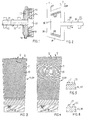
- the refiner with flat refining surfaces shown in Fig. 1 comprises a rotary refining disc (rotor) 10 on a shaft 11 supported in bearings 12,13.
- a stationary refining disc (stator) 14 is arranged opposite the rotary refining disc 10 so that a refiner gap 15 is formed between the refining surfaces on the rotor 10 and stator 14.
- the rotor 10 as well as the stator 14 are enclosed in an airtight casing 16, which has a central inlet 17 through the stator 14 inside the refiner gap for the material to be worked, and an outlet 18 for the refined material outside the refiner gap. The working is brought about by the relative rotation between the refining surfaces.
- the shaft 11 is movable for adjusting the size of the refiner gap 15 and for producing the required pressure between the refining surfaces.
- the refiner shown in Fig. 2 comprises a rotor 30 on a rotary shaft 31 supported in bearings 32,33.
- the rotor 30 is surrounded by a stator 34, in such a way, that a conical refiner gap 35 is formed between the refining surfaces on the rotor 30 and stator 34.
- the rotor 30 as well as the stator 34 are enclosed in an airtight casing 36, which has an inlet 37 at the narrower end of the conical refiner gap for the material to be worked, and an outlet 38 for the refined material at the opposite end. The working is brought about by the relative rotation between the refining surfaces.
- the shaft 31 is movable for adjusting the size of the refiner gap 35 and for producing the required pressure between the refining surfaces.
- the rotor 10,30 and stator 14,34 are provided with a plurality of refining elements 19,39.
- Each element 19,39 is formed with a refining surface comprising bars 20 and intermediate grooves 21 which extend substantially over the entire refining surface.
- the bars 20 form an angle of 50-85°, preferably 60-80°, with the radius or generatrix of the refining surface. This angle decreases, preferably successively, along the surface of the refining element 19,39 so that the bars 20 at the outlet portion form and angle between -25° and +25° with the radius or generatrix.
- each bar 20 forms a bow with successively decreasing angle from the inlet portion to the outlet portion.
- the total cross-sectional area of the grooves 21 in the inlet portion should substantially correspond to the total cross-sectional area of the grooves in the outlet portion.
- Fig. 5 and, respectively, Fig. 6 are cross-sections of the outlet and, respectively, inlet portion of the refining element 19,39. This implies that the bars 20 in the inlet portion should be located at a greater mutual distance than in the outlet portion.
- the design of the refining elements 19,39 has the object to bring about a uniform feed through the refiner gap.
- the centrifugal force, and thereby its feeding effect on the material is at the lowest.
- the feeding force increases along the refiner gap 15,35. Due to the angular shape of the bars 20, the feeding force varying in response to the centrifugal force can be compensated for so that a substantially uniform feed along the entire length of the refining element 19,39 is obtained. This implies that the pumping effect of the bars decreases outward, and it even can be negative, i.e. braking, in the outlet end of the refining element. See Fig. 4.
- the free inlet volume in the refiner gap 15,35 substantially corresponds to the free outlet volume. This can be achieved by arranging the bars 20 more sparsely in the inlet portion.
- the total cross-sectional area of the gooves 21 in the inlet portionn can substantially correspond to the total cross-sectional area of the grooves in the outlet portion.
Landscapes
- Engineering & Computer Science (AREA)
- Food Science & Technology (AREA)
- Mechanical Engineering (AREA)
- Crushing And Grinding (AREA)
- Paper (AREA)
- Mechanical Treatment Of Semiconductor (AREA)
- Crystals, And After-Treatments Of Crystals (AREA)
- Pharmaceuticals Containing Other Organic And Inorganic Compounds (AREA)
Abstract
Description
Claims (6)
- A refining element intended for a refiner with opposed refining surfaces, which are rotary relative to each other for working and refining lignocellulosic material during the passage of the material through a refiner gap (15,35) between the opposed refining surfaces from an inlet portion with smaller diameter to an outlet portion with greater diameter, which refining element (19,39) is formed with a refining surface with bars (20) and intermediate grooves (21) which extend over the entire refining element, the bars (20) in the inlet portion being located at a greater mutual distance than in the outlet portion,
characterized in that the bars (20) in the inlet portion of the refining element (19,39) form an angle of 50-85° with the radius or generatrix of the refining surface, and that the angle decreases outwards along the surface of the refining element (19,39), so that the bars (20) in the outlet portion form an angle between -25° and +25° with the radius or generatrix. - A refining element as defined in claim 1, characterized in that the total cross-sectional area of the grooves (21) in the inlet portion substantially corresponds to the total cross-sectional area of the grooves (21) in the outlet portion.
- A refining element as defined in claim 1 or 2, characterized in that each bar (20) forms a bow with successively decreasing angle from the inlet portion to the outlet portion.
- A refining element as defined in any one of the preceding claims, characterized in that the angle of the bars (20) in the inlet portion is 60-80°.
- A refining element as defined in any one of claims 1-4, characterized in that it is designed for a refiner with flat opposed refining surfaces.
- A refiner element as defined in any one of the claims 1-4, characterized in that it is designed for a refiner with conical opposed refining surfaces.
Applications Claiming Priority (5)
| Application Number | Priority Date | Filing Date | Title |
|---|---|---|---|
| SE9504608 | 1995-12-21 | ||
| SE9504608A SE505554C2 (en) | 1995-12-21 | 1995-12-21 | Refining element for lignocellulose pulp refiner |
| SE9602412A SE506822C2 (en) | 1996-06-18 | 1996-06-18 | Refining element for lignocellulose pulp refiner |
| SE9602412 | 1996-06-18 | ||
| PCT/SE1996/001594 WO1997023291A1 (en) | 1995-12-21 | 1996-12-04 | Refining element |
Publications (2)
| Publication Number | Publication Date |
|---|---|
| EP0958058A1 EP0958058A1 (en) | 1999-11-24 |
| EP0958058B1 true EP0958058B1 (en) | 2002-03-13 |
Family
ID=26662458
Family Applications (1)
| Application Number | Title | Priority Date | Filing Date |
|---|---|---|---|
| EP96943421A Expired - Lifetime EP0958058B1 (en) | 1995-12-21 | 1996-12-04 | Refining element |
Country Status (12)
| Country | Link |
|---|---|
| US (1) | US6042036A (en) |
| EP (1) | EP0958058B1 (en) |
| JP (1) | JP3833258B2 (en) |
| AT (1) | ATE214304T1 (en) |
| AU (1) | AU694898B2 (en) |
| BR (1) | BR9612150A (en) |
| CA (1) | CA2239337C (en) |
| DE (1) | DE69619877T2 (en) |
| ES (1) | ES2170287T3 (en) |
| NO (1) | NO313689B1 (en) |
| NZ (1) | NZ324882A (en) |
| WO (1) | WO1997023291A1 (en) |
Cited By (1)
| Publication number | Priority date | Publication date | Assignee | Title |
|---|---|---|---|---|
| US8226023B2 (en) | 2007-09-28 | 2012-07-24 | Metso Paper, Inc. | Refiner |
Families Citing this family (25)
| Publication number | Priority date | Publication date | Assignee | Title |
|---|---|---|---|---|
| FI108052B (en) * | 1998-04-16 | 2001-11-15 | M Real Oyj | refining segment |
| SE513807C2 (en) | 1999-03-19 | 2000-11-06 | Valmet Fibertech Ab | Grinding elements intended for disc type grinders for machining fiber material |
| US6402071B1 (en) * | 1999-11-23 | 2002-06-11 | Durametal Corporation | Refiner plates with injector inlet |
| CN1151917C (en) * | 2000-09-28 | 2004-06-02 | 住友橡胶工业株式会社 | Rubber waste treating apparatus and method |
| US20040144875A1 (en) * | 2001-01-08 | 2004-07-29 | J & L Fiber Services, Inc. | Deflection compensating refiner plate segment and method |
| WO2003090931A1 (en) * | 2002-04-25 | 2003-11-06 | Durametal Corporation | Refiner plates with logarithmic spiral bars |
| US7398938B2 (en) * | 2002-04-25 | 2008-07-15 | Andritz Inc. | Conical refiner plates with logarithmic spiral type bars |
| FI118971B (en) | 2002-07-02 | 2008-05-30 | Metso Paper Inc | Refiner |
| US20070029423A1 (en) * | 2003-03-04 | 2007-02-08 | Sigma Seiko Co., Ltd. | Crusher |
| FI119181B (en) * | 2003-06-18 | 2008-08-29 | Metso Paper Inc | refiner |
| US7478773B2 (en) * | 2006-01-09 | 2009-01-20 | Andritz Inc. | Tooth refiner plates having V-shaped teeth and refining method |
| US7472855B2 (en) * | 2006-01-09 | 2009-01-06 | Andritz Inc. | Refiner stator plate having an outer row of teeth slanted to deflect pulp and method for pulp deflection during refining |
| FI122364B (en) * | 2006-01-30 | 2011-12-30 | Metso Paper Inc | refiner |
| FI121929B (en) * | 2009-04-03 | 2011-06-15 | Metso Paper Inc | Refiner surface of refiner |
| JP5123404B2 (en) * | 2011-01-20 | 2013-01-23 | 日本製紙株式会社 | Pulp preparation method |
| FI125031B (en) * | 2011-01-27 | 2015-04-30 | Valmet Technologies Inc | Refiner and leaf elements |
| US9708765B2 (en) | 2011-07-13 | 2017-07-18 | Andritz Inc. | Rotor refiner plate element for counter-rotating refiner having curved bars and serrated leading edges |
| US9670615B2 (en) * | 2011-08-19 | 2017-06-06 | Andritz Inc. | Conical rotor refiner plate element for counter-rotating refiner having curved bars and serrated leading sidewalls |
| FI125608B (en) | 2012-05-15 | 2015-12-15 | Valmet Technologies Inc | Blade element |
| MY192042A (en) * | 2013-08-05 | 2022-07-24 | Sharp Kk | Mill and beverage preparation apparatus including the same |
| CN103911897B (en) * | 2014-04-01 | 2015-12-16 | 宁波市圣盾机械制造有限公司 | A kind of paper-making paste mill abrasive disc |
| FI10978U1 (en) * | 2014-05-26 | 2015-08-26 | Valmet Technologies Inc | Sheet steel refiner segment |
| JP6553956B2 (en) * | 2015-06-10 | 2019-07-31 | 相川鉄工株式会社 | Refiner refinement method and refiner |
| DE102017113795A1 (en) * | 2017-06-22 | 2018-12-27 | Voith Patent Gmbh | Fiber treatment arrangement |
| CN108319221B (en) * | 2018-01-24 | 2020-04-21 | 东莞长盈精密技术有限公司 | Tool path calculation method and middle frame machining method |
Family Cites Families (5)
| Publication number | Priority date | Publication date | Assignee | Title |
|---|---|---|---|---|
| US100537A (en) * | 1870-03-08 | Improved mill-stone dress | ||
| US3974971A (en) * | 1972-04-13 | 1976-08-17 | Rolf Bertil Reinhall | Grinding discs for defibering fibrous material |
| US4023737A (en) * | 1976-03-23 | 1977-05-17 | Westvaco Corporation | Spiral groove pattern refiner plates |
| US5181664A (en) * | 1992-04-17 | 1993-01-26 | Andritz Sprout-Bauer, Inc. | Grinding plate with angled outer bars |
| SE470566B (en) * | 1993-01-14 | 1994-08-29 | Sunds Defibrator Ind Ab | Grinding elements intended for a disk mill for defibration and processing of lignocellulosic fibrous material |
-
1996
- 1996-12-04 CA CA002239337A patent/CA2239337C/en not_active Expired - Lifetime
- 1996-12-04 AT AT96943421T patent/ATE214304T1/en not_active IP Right Cessation
- 1996-12-04 NZ NZ324882A patent/NZ324882A/en unknown
- 1996-12-04 ES ES96943421T patent/ES2170287T3/en not_active Expired - Lifetime
- 1996-12-04 EP EP96943421A patent/EP0958058B1/en not_active Expired - Lifetime
- 1996-12-04 AU AU12157/97A patent/AU694898B2/en not_active Ceased
- 1996-12-04 BR BR9612150A patent/BR9612150A/en not_active IP Right Cessation
- 1996-12-04 DE DE69619877T patent/DE69619877T2/en not_active Expired - Fee Related
- 1996-12-04 US US09/091,447 patent/US6042036A/en not_active Expired - Lifetime
- 1996-12-04 WO PCT/SE1996/001594 patent/WO1997023291A1/en not_active Ceased
- 1996-12-04 JP JP52355497A patent/JP3833258B2/en not_active Expired - Fee Related
-
1998
- 1998-06-19 NO NO19982846A patent/NO313689B1/en not_active IP Right Cessation
Cited By (1)
| Publication number | Priority date | Publication date | Assignee | Title |
|---|---|---|---|---|
| US8226023B2 (en) | 2007-09-28 | 2012-07-24 | Metso Paper, Inc. | Refiner |
Also Published As
| Publication number | Publication date |
|---|---|
| DE69619877D1 (en) | 2002-04-18 |
| US6042036A (en) | 2000-03-28 |
| JP2000502600A (en) | 2000-03-07 |
| AU1215797A (en) | 1997-07-17 |
| BR9612150A (en) | 1999-07-13 |
| CA2239337A1 (en) | 1997-07-03 |
| ES2170287T3 (en) | 2002-08-01 |
| NO313689B1 (en) | 2002-11-18 |
| NZ324882A (en) | 1999-05-28 |
| JP3833258B2 (en) | 2006-10-11 |
| EP0958058A1 (en) | 1999-11-24 |
| NO982846D0 (en) | 1998-06-19 |
| ATE214304T1 (en) | 2002-03-15 |
| NO982846L (en) | 1998-06-19 |
| WO1997023291A1 (en) | 1997-07-03 |
| DE69619877T2 (en) | 2002-11-28 |
| AU694898B2 (en) | 1998-07-30 |
| CA2239337C (en) | 2005-02-08 |
Similar Documents
| Publication | Publication Date | Title |
|---|---|---|
| AU694898B2 (en) | Refining element | |
| CA2639890C (en) | Multi-zone paper fiber refiner | |
| CN101605938B (en) | Mechanical refiner discs with uneven front sidewalls on curved bars and method of designing discs | |
| US5975438A (en) | Refiner disc with curved refiner bars | |
| US8573522B2 (en) | Refiner and method for refining fibrous material | |
| JP4485356B2 (en) | Refiner surface for refiner to make lignocellulose-containing material into fiber | |
| US5947394A (en) | Paper pulp refiner control system and method | |
| EP0611599A1 (en) | Refining segment | |
| JPH0784717B2 (en) | Sorting device with a reducer | |
| KR890000818B1 (en) | Refining apparatus of fibrous material | |
| US6499682B1 (en) | Refining elements | |
| US5779168A (en) | Refiner and tooling for refining suspended fibrous material | |
| WO2021229153A1 (en) | Blade element for refiner | |
| CA2983614A1 (en) | Treatment fitting for the treatment of aqueously suspended fibrous material | |
| US7726596B2 (en) | Refiner with spiral inlet and dual tangential discharge outlet | |
| WO1997018037A1 (en) | A pair of co-operating refining elements intended for a disc refiner | |
| CN107109789B (en) | Pulp grinding device | |
| FI3899135T3 (en) | Refining arrangement | |
| US20110253327A1 (en) | Method for refining cellulose fibers in aqueous suspension as well as refiner filling to implement said method | |
| EP2279041B1 (en) | A refining segment for pulp processing with a deflector arrangement | |
| US7451946B2 (en) | Refining element | |
| US20220333303A1 (en) | Flow-altering refiner segment | |
| CN115698423B (en) | Blade segment for a refiner | |
| JP7554758B2 (en) | Double Disc Refiner | |
| US2995310A (en) | Paper machinery |
Legal Events
| Date | Code | Title | Description |
|---|---|---|---|
| PUAI | Public reference made under article 153(3) epc to a published international application that has entered the european phase |
Free format text: ORIGINAL CODE: 0009012 |
|
| 17P | Request for examination filed |
Effective date: 19980519 |
|
| AK | Designated contracting states |
Kind code of ref document: A1 Designated state(s): AT BE DE ES FI FR GB IT NL SE |
|
| RAP1 | Party data changed (applicant data changed or rights of an application transferred) |
Owner name: VALMET FIBERTECH AB |
|
| GRAG | Despatch of communication of intention to grant |
Free format text: ORIGINAL CODE: EPIDOS AGRA |
|
| 17Q | First examination report despatched |
Effective date: 20010612 |
|
| GRAG | Despatch of communication of intention to grant |
Free format text: ORIGINAL CODE: EPIDOS AGRA |
|
| GRAH | Despatch of communication of intention to grant a patent |
Free format text: ORIGINAL CODE: EPIDOS IGRA |
|
| GRAH | Despatch of communication of intention to grant a patent |
Free format text: ORIGINAL CODE: EPIDOS IGRA |
|
| REG | Reference to a national code |
Ref country code: GB Ref legal event code: IF02 |
|
| GRAA | (expected) grant |
Free format text: ORIGINAL CODE: 0009210 |
|
| RIN1 | Information on inventor provided before grant (corrected) |
Inventor name: HAWEN, ANDERS Inventor name: BERGQUIST, PETER Inventor name: VIRVING, NILS |
|
| AK | Designated contracting states |
Kind code of ref document: B1 Designated state(s): AT BE DE ES FI FR GB IT NL SE |
|
| PG25 | Lapsed in a contracting state [announced via postgrant information from national office to epo] |
Ref country code: NL Free format text: LAPSE BECAUSE OF FAILURE TO SUBMIT A TRANSLATION OF THE DESCRIPTION OR TO PAY THE FEE WITHIN THE PRESCRIBED TIME-LIMIT Effective date: 20020313 Ref country code: BE Free format text: LAPSE BECAUSE OF FAILURE TO SUBMIT A TRANSLATION OF THE DESCRIPTION OR TO PAY THE FEE WITHIN THE PRESCRIBED TIME-LIMIT Effective date: 20020313 |
|
| REF | Corresponds to: |
Ref document number: 214304 Country of ref document: AT Date of ref document: 20020315 Kind code of ref document: T |
|
| REF | Corresponds to: |
Ref document number: 69619877 Country of ref document: DE Date of ref document: 20020418 |
|
| NLV1 | Nl: lapsed or annulled due to failure to fulfill the requirements of art. 29p and 29m of the patents act | ||
| REG | Reference to a national code |
Ref country code: ES Ref legal event code: FG2A Ref document number: 2170287 Country of ref document: ES Kind code of ref document: T3 |
|
| ET | Fr: translation filed | ||
| PG25 | Lapsed in a contracting state [announced via postgrant information from national office to epo] |
Ref country code: GB Free format text: LAPSE BECAUSE OF NON-PAYMENT OF DUE FEES Effective date: 20021204 |
|
| PLBE | No opposition filed within time limit |
Free format text: ORIGINAL CODE: 0009261 |
|
| STAA | Information on the status of an ep patent application or granted ep patent |
Free format text: STATUS: NO OPPOSITION FILED WITHIN TIME LIMIT |
|
| 26N | No opposition filed |
Effective date: 20021216 |
|
| GBPC | Gb: european patent ceased through non-payment of renewal fee | ||
| PGFP | Annual fee paid to national office [announced via postgrant information from national office to epo] |
Ref country code: ES Payment date: 20081222 Year of fee payment: 13 Ref country code: AT Payment date: 20081223 Year of fee payment: 13 |
|
| PGFP | Annual fee paid to national office [announced via postgrant information from national office to epo] |
Ref country code: IT Payment date: 20081220 Year of fee payment: 13 |
|
| PGFP | Annual fee paid to national office [announced via postgrant information from national office to epo] |
Ref country code: DE Payment date: 20081218 Year of fee payment: 13 |
|
| PGFP | Annual fee paid to national office [announced via postgrant information from national office to epo] |
Ref country code: FR Payment date: 20081231 Year of fee payment: 13 |
|
| PG25 | Lapsed in a contracting state [announced via postgrant information from national office to epo] |
Ref country code: AT Free format text: LAPSE BECAUSE OF NON-PAYMENT OF DUE FEES Effective date: 20091204 |
|
| REG | Reference to a national code |
Ref country code: FR Ref legal event code: ST Effective date: 20100831 |
|
| PG25 | Lapsed in a contracting state [announced via postgrant information from national office to epo] |
Ref country code: FR Free format text: LAPSE BECAUSE OF NON-PAYMENT OF DUE FEES Effective date: 20091231 |
|
| PG25 | Lapsed in a contracting state [announced via postgrant information from national office to epo] |
Ref country code: DE Free format text: LAPSE BECAUSE OF NON-PAYMENT OF DUE FEES Effective date: 20100701 |
|
| REG | Reference to a national code |
Ref country code: ES Ref legal event code: FD2A Effective date: 20110328 |
|
| PG25 | Lapsed in a contracting state [announced via postgrant information from national office to epo] |
Ref country code: IT Free format text: LAPSE BECAUSE OF NON-PAYMENT OF DUE FEES Effective date: 20091204 |
|
| PG25 | Lapsed in a contracting state [announced via postgrant information from national office to epo] |
Ref country code: ES Free format text: LAPSE BECAUSE OF NON-PAYMENT OF DUE FEES Effective date: 20110314 |
|
| PG25 | Lapsed in a contracting state [announced via postgrant information from national office to epo] |
Ref country code: ES Free format text: LAPSE BECAUSE OF NON-PAYMENT OF DUE FEES Effective date: 20091205 |
|
| PGFP | Annual fee paid to national office [announced via postgrant information from national office to epo] |
Ref country code: FI Payment date: 20151217 Year of fee payment: 20 |
|
| PGFP | Annual fee paid to national office [announced via postgrant information from national office to epo] |
Ref country code: SE Payment date: 20151222 Year of fee payment: 20 |
|
| REG | Reference to a national code |
Ref country code: SE Ref legal event code: EUG |