EP0957239B1 - Arrangement for the control of a device varying the lift of a valve of an internal combustion engine for the circulation of the inlet or outlet gas - Google Patents
Arrangement for the control of a device varying the lift of a valve of an internal combustion engine for the circulation of the inlet or outlet gas Download PDFInfo
- Publication number
- EP0957239B1 EP0957239B1 EP99109119A EP99109119A EP0957239B1 EP 0957239 B1 EP0957239 B1 EP 0957239B1 EP 99109119 A EP99109119 A EP 99109119A EP 99109119 A EP99109119 A EP 99109119A EP 0957239 B1 EP0957239 B1 EP 0957239B1
- Authority
- EP
- European Patent Office
- Prior art keywords
- camshaft
- rotation
- angle
- actuator
- crankshaft
- Prior art date
- Legal status (The legal status is an assumption and is not a legal conclusion. Google has not performed a legal analysis and makes no representation as to the accuracy of the status listed.)
- Expired - Lifetime
Links
Images


Classifications
-
- F—MECHANICAL ENGINEERING; LIGHTING; HEATING; WEAPONS; BLASTING
- F01—MACHINES OR ENGINES IN GENERAL; ENGINE PLANTS IN GENERAL; STEAM ENGINES
- F01L—CYCLICALLY OPERATING VALVES FOR MACHINES OR ENGINES
- F01L13/00—Modifications of valve-gear to facilitate reversing, braking, starting, changing compression ratio, or other specific operations
- F01L13/0015—Modifications of valve-gear to facilitate reversing, braking, starting, changing compression ratio, or other specific operations for optimising engine performances by modifying valve lift according to various working parameters, e.g. rotational speed, load, torque
- F01L13/0036—Modifications of valve-gear to facilitate reversing, braking, starting, changing compression ratio, or other specific operations for optimising engine performances by modifying valve lift according to various working parameters, e.g. rotational speed, load, torque the valves being driven by two or more cams with different shape, size or timing or a single cam profiled in axial and radial direction
- F01L13/0047—Modifications of valve-gear to facilitate reversing, braking, starting, changing compression ratio, or other specific operations for optimising engine performances by modifying valve lift according to various working parameters, e.g. rotational speed, load, torque the valves being driven by two or more cams with different shape, size or timing or a single cam profiled in axial and radial direction the movement of the valves resulting from the sum of the simultaneous actions of at least two cams, the cams being independently variable in phase in respect of each other
Definitions
- the invention relates to a control device for a device for adjusting the Ventilhubverlaufs a gas exchange valve an internal combustion engine and a method for Controlling a device for adjusting the Ventilhubverlaufs a gas exchange valve of an internal combustion engine according to Preamble of claim 1 and 2, respectively.
- From DE 42 44 550 A1 discloses a device for adjusting the Ventilhubverlaufs a gas exchange valve of an internal combustion engine known, preferably for throttle-free Load control of gasoline engines is used.
- the device has two counter rotating camshafts, which over a swing lever act on the gas exchange valve.
- One of the Camshafts determines the open function and the other camshaft determines the closing function of the gas exchange valve.
- the valve lift course of the gas exchange valve, d. H. of the Stroke and the opening time, can be changed in many areas be due to a relative rotation of the two camshafts against each other by means of a four-wheeled linkage.
- the four-wheeled linkage has a drive wheel that with the fixed by the crankshaft first camshaft is connected, and a driven gear, with the second camshaft is firmly connected.
- the drive and the driven wheel are engaged with each other via two intermediate gears, that by acting on the coupling rotary Adjustment a rolling of the intermediate wheels on the arrival and Output wheels takes place and thus a relative rotation of the two camshafts against each other is achieved.
- the security requirements in internal combustion engines are constantly increasing.
- a device for adjusting the Ventilhubverlaufs a Gas exchange valve of an internal combustion engine and a method for controlling such a device according to the generic terms of claims 1 and 2 is known from DE 19501386A1 known.
- the device disclosed therein includes the Actuator, for example, a hydraulically operating actuator for adjusting the coupling of a linkage, that is the phase of the second camshaft relative to the first camshaft sets.
- the actuator sensor detects the angle of rotation of the paddock.
- the controller determines then depending on the instantaneous speed of the Internal combustion engine and the angle of rotation of the coupling, if necessary additionally of a temporal differential this Angle of rotation, values for controlling the actuator.
- An internal combustion engine 1 has, preferably in a cylinder head, a device 11 for adjusting the valve lift a gas exchange valve 12.
- the device 11 comprises a first camshaft 111, which mechanically with a crankshaft 13, for example via a chain drive, not shown, is coupled.
- a second camshaft 112 is mechanical with the first camshaft 111 via a coupling gear coupled, which has a coupling 113 and a first gear 114 and a second gear 115 includes.
- An actuator 116 is provided which has a motor, preferably as a simpler Synchronous motor 1161 formed with an electronic commutation is.
- the actuator further includes a drive shaft 1162 which via a worm wheel 1163 with a not connected eccentric wheel is connected, which is coaxial with the second camshaft 112 is disposed and with the second Camshaft 112 is firmly connected.
- a rotation of the drive shaft 1162 is via the worm wheel 1163 on the eccentric transfer.
- the first camshaft 111 and the second camshaft 112 point each cam 1111 and 1121 ( Figure 2) on.
- the cams act via a transfer member 117, which acts as a bucket tappet, Drag lever, rocker arm or other known transmission element may be formed on the gas exchange valve 12th one.
- the first camshaft 111 is the valve lift beginning specified.
- the stroke of the second camshaft 112 the valve stroke end is specified.
- the stroke course the first or second camshaft 111, 112 is through the contour of a vertical axis of rotation of the camshaft Section through the first or second camshaft 111, 112 certainly.
- the stroke course is given by the distance of the Points on the surface of the first cam shaft 111 or second camshaft 112 to the respective axis of rotation.
- the phase is determined by an angle between a Vector perpendicular to the axis of rotation of the first camshaft lies and whose base is the axis of rotation and its end point is a predetermined point on the circumference of the camshaft, and another vector perpendicular to the axis of rotation of the second camshaft, whose base point in the axis of rotation the second camshaft 112 is located and its end point given point on the circumference of the second camshaft where one of the vectors for determining the phase is parallel shifted so that its base with the foot the further vector coincides.
- the transmission member 117 is formed so that it the Hubverlauf the first camshaft 111 and the second camshaft 112 transmits only to the gas exchange valve 12, if both Cams 1111, 1121 simultaneously on the transmission link 117 act.
- the valve stroke end be varied.
- the phase is adjusted so that the valve lift begins is variable.
- the device 11 is associated with a control device 2 (FIG. 1), depending on a rotation angle DRV of the drive shaft 1162, which is detected by an actuator sensor 3, a rotational angle CRK of the crankshaft 112, that of a crankshaft sensor 4 is detected, a rotation angle CAM of the second Camshaft 112, which is detected by a camshaft sensor 5 is and preferably further operating variables of the internal combustion engine an actuating signal for the synchronous motor 1161 determined.
- the actuator also Functions for monitoring the actuator sensor 3, the Crankshaft sensor 4 and the camshaft sensor 5 processed.
- the control device 2 is also for Taxes the injectors and a throttle valve, not shown the internal combustion engine formed.
- the actuator 116 is formed when detected by the actuator sensor 3 Rotation angle DRV additionally a signal for commutating the Current generated by the armature winding of the synchronous motor 1161 becomes.
- the actuator sensor 3 can then directly in Synchronous motor 1161 are arranged.
- FIG. 3 shows a flow diagram of a function for determining the rotational angle DRV of the drive shaft 1162, in the control device 2 is processed.
- the actuator sensor 3 comprises a arranged on the drive shaft magnetic wheel with a predetermined number of pole pairs (eg 32) and one predetermined number (eg 2) of Hall elements, the phase-shifted are arranged in the housing of the electric motor 1161.
- Step S1 the start takes place and the values of the counters i, k are read from a data memory.
- Step S2 checks whether the measurement signal of the first Hall element of the actuator sensor 3 has a flank. Is this not the case, then after a given waiting time the Processing continued in step S2. Is this however Case, then in a step S3 by evaluating the Measuring signals of the first and second Hall element the direction of rotation the drive shaft 1162 determined. Is the direction of rotation the drive shaft 1162 a predetermined direction of rotation, so will In step S4, the counter i is incremented. Is this however not the case, then in a step S5, the counter i decremented.
- a step S6 it is checked whether the counter i is a maximum value imax corresponding to the number of pole pairs of the magnet wheel has (eg 32). If this is the case, it will be in one Step S7 the counter k is incremented. The counter k is on Measured for the number of revolutions of the drive shaft 1162 to a reference angle. This reference angle can, depending on the configuration of the device 11, the rotation angle of Drive shaft 1162, in which the phase of the second camshaft 112 relative to the first camshaft 111 a minimum or maximum value.
- the Counter i reset, z. B. occupied with the value zero.
- a step S8 a it is checked whether the counter i is the negative Maximum value imax has. If this is the case, it will be in one Step S8b decrements the counter k and in one step S8c the counter i reset.
- a step S9 the rotation angle DRV of the drive shaft becomes 1162 depending on the counters i and k determined.
- the value of Counter k corresponds to the number of revolutions of the drive shaft 1162 relative to the reference point and the counter k corresponds to the angle during a rotation of the drive shaft with a resolution that depends on the number of pole pairs.
- the variables k and i in the data memory saved. Preference is given to steps S1 to S9 in the form of an interrupt routine (interrupt routine) executed.
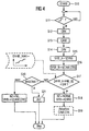
- a step S10 (FIG. 4), the start of a second takes place Program part, which is processed in the control device 2 becomes.
- a step S11 it is checked whether the measurement signal of the camshaft sensor 5 has a flank.
- the camshaft sensor 5 is preferably as a simple Hall sensor with a two-pole magnetic wheel formed on the second Camshaft 112 is arranged. The measuring signal of the camshaft sensor 5 thus provides two signal edges per revolution the second camshaft 112.
- step S11 Indicates the measurement signal of the camshaft sensor 5 in the step If there is no edge on S11, it will be after a specified waiting time the processing continues again in step S1. Otherwise, in steps S12 to S14, the current ones Angle of rotation CRK, CAM, DRV of the crankshaft 13, the second camshaft 112 and the drive shaft 1162 is read.
- a first value VHB_A of the valve lift start becomes the gas exchange valve 12 depending on the angle of rotation DRV of the drive shaft 1162 determined.
- the first value VHB_A preferably depends on a first characteristic curve determined by the rotation angle DRV of the drive shaft 1162.
- a step S16 becomes a second value VHB_B of the valve lift start depending on the rotation angle CAM of the second camshaft and the rotational angle CRK of the crankshaft 13 and determined Although preferably from a first map depending on the Rotation angles CAM, CRK.
- a step S17 it is checked whether the first value VHB_A from the second value VHB_B less than a predetermined one Threshold SW deviates. If this is the case, it will be on one error-free operation of the actuator sensor 3 is closed and in a step S18 the operating state BZ Normal NORM taken.
- the operating state BZ Normal NORM is the valve lift start VHB depends on the rotation angle DRV of the Drive shaft 1162 determined and again preferably out the first characteristic.
- valve lift start VHB is the valve lift curve of the Gas exchange valve 12 characterizing size. Further the Values that characterize valve lift are, for example the valve lift end if the valve lift end is variably adjustable is, or one over the entire opening duration of the Gas exchange valve 12 during a cycle of the internal combustion engine integrated opening area.
- a step S19 can at predetermined intervals an adaptation of the rotation angle CAM, which is detected by the camshaft sensor 5, and the Angle of rotation CRK detected by the crankshaft sensor 4 will be done.
- the rotation angle DRV of the actuator shaft 1162 taking into account the translation of the Worm gear and the current angle CRK the Crankshaft 13 in a desired value of the angle of rotation CAM of second camshaft 112 converted. From the setpoint and the determined by the camshaft sensor 5 rotation angle DRV the second camshaft 112 is then determined a correction value, with the detected by the camshaft sensor 5 rotation angle CAM is corrected.
- a desired value of the rotational angle of the crankshaft 13 dependent from the rotation angle DRV of the drive shaft 1162 and the Rotation angle CAM of the second camshaft 112 can be determined.
- a correction value determined with the angle of rotation CRK of the crankshaft is corrected. So inaccuracies can easily when installing the camshaft sensor 5 or the crankshaft sensor and manufacturing inaccuracies of the crankshaft sensor 4 and the camshaft sensor 5 can be compensated.
- Step S20 checks whether the internal combustion engine is in the State of the start BKSTART is located. If this is the case, then In step S21, the value of the counter k becomes dependent on the rotation angle CRK of the crankshaft 13 and the rotation angle CAM the second camshaft 112 determined. The counter is then set to this value, so initialized. That's easy be avoided that the drive shaft 1162 of the actuator 116 after a start of the internal combustion engine to the given reference point must be driven.
- step S20 If the condition of step S20 is not met, then the Operating status of the BZ of the emergency NL taken.
- the valve lift beginning VHB then becomes dependent on the angles of rotation CAM, CRK of the second camshaft 112 and the crankshaft 13 is determined and preferably from the first map.
- Emergency running NL is then the load control of the internal combustion engine via a load actuator, for example, a throttle is.
- the actuator 16 is then controlled by the controller 2 no longer activated, since the rotation angle DRV the drive shaft is no longer error free from the Stellantriebssersor 3 is detected and thus the timely commutation the armature current is no longer guaranteed.
- Valve lift start VHB From the Valve lift start VHB then becomes a valve lift curve of the Gas-valve characterizing size determined, the then as a correction value in determining a control signal is taken into account for the load actuator. So that's one comfortable emergency running ensures that the driver's request a driver of the motor vehicle with the control device 2 exactly in a corresponding to be delivered by the internal combustion engine Torque can be implemented.
- valve lift beginning VHB also another the valve lift of the gas exchange valve 12 characterizing size are determined and then the processing of steps S15 to S22 based on this Size done.
- the drive shaft is preferred 1162 ensured that the rotation angle CAM, CRK the second camshaft 112 and the crankshaft 13 error-free be detected.
- crankshaft sensor be monitored with the camshaft sensor. It is therefore only necessary, exactly one camshaft sensor for both Provide camshafts.
- Characteristic curves or characteristic diagrams are by investigations at a Engine test bench or determined by driving tests.
Description
Die Erfindung betrifft eine Steuereinrichtung für eine Vorrichtung
zum Verstellen des Ventilhubverlaufs eines Gaswechselventils
einer Brennkraftmaschine und ein Verfahren zum
Steuern einer Vorrichtung zum Verstellen des Ventilhubverlaufs
eines Gaswechselventils einer Brennkraftmaschine gemäß
Oberbegriff von Patentanspruch 1 bzw. 2.The invention relates to a control device for a device
for adjusting the Ventilhubverlaufs a gas exchange valve
an internal combustion engine and a method for
Controlling a device for adjusting the Ventilhubverlaufs
a gas exchange valve of an internal combustion engine according to
Preamble of
Aus der DE 42 44 550 A1 ist eine Vorrichtung zum Verstellen des Ventilhubverlaufs eines Gaswechselventils einer Brennkraftmaschine bekannt, die vorzugsweise zur drosselfreien Laststeuerung von Ottomotoren eingesetzt wird. Die Vorrichtung hat zwei gegensinnig drehende Nockenwellen, welche über einen Schwinghebel auf das Gaswechselventil wirken. Eine der Nockenwellen bestimmt die Öffnet-Funktion und die andere Nockenwelle bestimmt die Schließt-Funktion des Gaswechselventils. Der Ventilhubverlauf des Gaswechselventils, d. h. der Hub und die Öffnungsdauer, kann in weiten Bereichen verändert werden durch eine relative Verdrehung der beiden Nockenwellen gegeneinander mittels eines vierrädrigen Koppelgetriebes. Das vier-rädrige Koppelgetriebe hat ein Antriebsrad, das mit der von der Kurbelwelle angetriebenen ersten Nockenwelle fest verbunden ist, und ein Abtriebsrad, das mit der zweiten Nockenwelle fest verbunden ist. Das Antriebs- und das Abtriebsrad stehen über zwei Zwischenräder miteinander derart im Eingriff, daß durch eine an den Koppeln angreifende rotatorische Verstellung ein Abrollen der Zwischenräder auf den An- und Abtriebsrädern erfolgt und somit eine relative Verdrehung der beiden Nockenwellen gegeneinander erreicht wird. Die Sicherheitsanforderungen bei Brennkraftmaschinen nehmen ständig zu. From DE 42 44 550 A1 discloses a device for adjusting the Ventilhubverlaufs a gas exchange valve of an internal combustion engine known, preferably for throttle-free Load control of gasoline engines is used. The device has two counter rotating camshafts, which over a swing lever act on the gas exchange valve. One of the Camshafts determines the open function and the other camshaft determines the closing function of the gas exchange valve. The valve lift course of the gas exchange valve, d. H. of the Stroke and the opening time, can be changed in many areas be due to a relative rotation of the two camshafts against each other by means of a four-wheeled linkage. The four-wheeled linkage has a drive wheel that with the fixed by the crankshaft first camshaft is connected, and a driven gear, with the second camshaft is firmly connected. The drive and the driven wheel are engaged with each other via two intermediate gears, that by acting on the coupling rotary Adjustment a rolling of the intermediate wheels on the arrival and Output wheels takes place and thus a relative rotation of the two camshafts against each other is achieved. The security requirements in internal combustion engines are constantly increasing.
Dies gilt insbesondere für Komponenten, die zur Laststeuerung der Brennkraftmaschine vorgesehen sind.This is especially true for components that load control the internal combustion engine are provided.
Eine Vorrichtung zum Verstellen des Ventilhubverlaufs eines
Gaswechselventils einer Brennkraftmaschine sowie ein Verfahren
zum Steuern einer solchen Vorrichtung nach den Oberbegriffen
der Patentansprüche 1 und 2 ist aus der DE 19501386A1
bekannt. Bei der dort offenbarten Vorrichtung umfasst der
Stellantrieb eine beispielsweise hydraulisch arbeitende Betätigungsvorrichtung
zum Verstellen der Koppel eines Koppelgetriebes,
das die Phase der zweiten Nockenwelle relativ zu der
ersten Nockenwelle einstellt. Der Stellantriebssensor erfasst
den Drehwinkel der Koppel. Die Steuereinrichtung ermittelt
dann in Abhängigkeit von der augenblicklichen Drehzahl der
Brennkraftmaschine und dem Drehwinkel der Koppel, gegebenenfalls
zusätzlich von einem zeitlichen Differential dieses
Drehwinkels, Werte zur Ansteuerung des Stellantriebs.A device for adjusting the Ventilhubverlaufs a
Gas exchange valve of an internal combustion engine and a method
for controlling such a device according to the generic terms
of
Es ist Aufgabe der Erfindung, eine Vorrichtung zum Verstellen des Ventilhubverlaufs eines Gaswechselventils einer Brennkraftmaschine sowie ein Verfahren zum Steuern einer solchen Vorrichtung zu schaffen, welche ein sicheres Ermitteln mindestens einer den Ventilhubverlauf charakterisierenden Größe gewährleistet und gleichzeitig einfach und kostengünstig sind.It is an object of the invention to provide a device for adjusting the Ventilhubverlaufs a gas exchange valve of an internal combustion engine and a method for controlling such Device to create, which is a certain determination at least a variable characterizing the Ventilhubverlaufisizing guaranteed and at the same time simple and inexpensive are.
Die Aufgabe wird durch die Merkmale der Patentansprüche 1
bzw. 2 gelöst.The object is achieved by the features of
Vorteilhafte Ausgestaltungen der Erfindung ergeben sich aus den Unteransprüchen.Advantageous embodiments of the invention will become apparent the dependent claims.
Ausführungsbeispiele der Erfindung sind anhand der schematischen Zeichnungen näher erläutert. Es zeigen:
- Figur 1:
- eine erste Ansicht einer Brennkraftmaschine mit einer
erfindungsgemäßen Steuereinrichtung 2, - Figur 2:
- eine zweite Ansicht der Brennkraftmaschine,
- Figur 3:
- ein Ablaufdiagramm eines ersten Teils eines Programms,
das in der
Steuereinrichtung 2 abgearbeitet wird, - Figur 4:
- einen zweiten Teil des Programms, das in der
Steuereinrichtung 2 abgearbeitet wird.
- FIG. 1:
- a first view of an internal combustion engine with a
control device 2 according to the invention, - FIG. 2:
- a second view of the internal combustion engine,
- FIG. 3:
- a flowchart of a first part of a program which is executed in the
control device 2, - FIG. 4:
- a second part of the program, which is processed in the
control device 2.
Elemente gleicher Konstruktion und Funktion sind figurenübergreifend mit den gleichen Bezugszeichen versehen.Elements of the same construction and function are cross-figurative provided with the same reference numerals.
Eine Brennkraftmaschine 1 hat, vorzugsweise in einem Zylinderkopf,
eine Vorrichtung 11 zum Verstellen des Ventilhubs
eines Gaswechselventils 12. Die Vorrichtung 11 umfaßt eine
erste Nockenwelle 111, die mechanisch mit einer Kurbelwelle
13, beispielsweise über einen nicht dargestellten Kettentrieb,
gekoppelt ist. Eine zweite Nockenwelle 112 ist mechanisch
mit der ersten Nockenwelle 111 über ein Koppelgetriebe
gekoppelt, das eine Koppel 113 und ein erstes Zahnrad 114 und
ein zweites Zahnrad 115 umfaßt. Ein Stellantrieb 116 ist vorgesehen,
der einen Motor hat, der vorzugsweise als einfacher
Synchronmotor 1161 mit einer elektronischen Kommutierung ausgebildet
ist. Der Stellantrieb umfaßt ferner eine Antriebswelle
1162 die über ein Schneckenrad 1163 mit einem nicht
dargestellten Exzenterrad verbunden ist, das koaxial zu der
zweiten Nockenwelle 112 angeordnet ist und mit der zweiten
Nockenwelle 112 fest verbunden ist. Eine Drehung der Antriebswelle
1162 wird über das Schneckenrad 1163 auf das Exzenterrad
übertragen. Durch das Rotieren des Exzenterrades
erfolgt ein Verändern der Lage der zweiten Nockenwelle 112
bezüglich der ersten Nockenwelle 111, in der mit dem Pfeil
dargestellten Richtung.An
Die erste Nockenwelle 111 und die zweite Nockenwelle 112 weisen
jeweils Nocken 1111 und 1121 (Figur 2) auf. Die Nocken
wirken über ein Übertragungsglied 117, das als Tassenstößel,
Schlepphebel, Schwinghebel oder sonstiges bekanntes Übertragungsglied
ausgebildet sein kann, auf das Gaswechselventil 12
ein.The
Durch den Hubverlauf der ersten Nockenwelle 111 ist der Ventilhubbeginn
vorgegeben. Durch den Hubverlauf der zweiten Nockenwelle
112 ist das Ventilhubende vorgegeben. Der Hubverlauf
der ersten oder zweiten Nockenwelle 111, 112 ist durch
die Kontur eines zur Drehachse der Nockenwelle senkrechten
Schnittes durch die erste oder zweite Nockenwelle 111, 112
bestimmt. Der Hubverlauf ist vorgegeben durch den Abstand der
Punkte auf der Oberfläche der ersten Nockenwelle 111 oder
zweiten Nockenwelle 112 zu der jeweiligen Drehachse.Through the Hubverlauf the
Durch das Verstellen der Lage der zweiten Nockenwelle 112 zu
der ersten Nockenwelle 111 folgt ein Verstellen der Phase der
zweiten Nockenwelle 112 relativ zu der ersten Nockenwelle
111. Die Phase ist bestimmt durch einen Winkel zwischen einem
Vektor, der senkrecht zur Drehachse der ersten Nockenwelle
liegt und dessen Fußpunkt die Drehachse und dessen Endpunkt
ein vorgegebener Punkt auf dem Umfang der Nockenwelle ist,
und einem weiteren Vektor, der senkrecht zu der Drehachse der
zweiten Nockenwelle liegt, dessen Fußpunkt in der Drehachse
der zweiten Nockenwelle 112 liegt und dessen Endpunkt ein
vorgegebener Punkt auf dem Umfang der zweiten Nockenwelle
ist, wobei einer der Vektoren zum Bestimmen der Phase parallel
derart verschoben ist, daß sein Fußpunkt mit dem Fußpunkt
des weiteren Vektors zusammenfällt.By adjusting the position of the
Das Übertragungsglied 117 ist so ausgebildet, daß es den Hubverlauf
der ersten Nockenwelle 111 und zweiten Nockenwelle
112 nur dann auf das Gaswechselventil 12 überträgt, wenn beide
Nocken 1111, 1121 gleichzeitig auf das Übertragungsglied
117 einwirken. Durch das Verstellen der Phase der zweiten Nockenwelle
112 zu der ersten Nockenwelle 111 kann das Ventilhubende
variiert werden. In einer alternativen Ausführungsform
erfolgt ein Verstellen der Phase derart, daß der Ventilhubbeginn
variabel ist.The
Der Vorrichtung 11 ist eine Steuereinrichtung 2 (Figur 1) zugeordnet,
die abhängig von einem Drehwinkel DRV der Antriebswelle
1162, der von einem Stellantriebssensor 3 erfaßt wird,
einem Drehwinkel CRK der Kurbelwelle 112, der von einem Kurbelwellensensor
4 erfaßt wird, einem Drehwinkel CAM der zweiten
Nockenwelle 112, der von einem Nockenwellensensor 5 erfaßt
wird und vorzugsweise weiteren Betriebsgrößen der Brennkraftmaschine
ein Stellsignal für den Synchronmotor 1161 ermittelt.
Darüber hinaus werden in der Stelleinrichtung auch
Funktionen zum Überwachen des Stellantriebssensors 3, des
Kurbelwellensensors 4 und des Nockenwellensensors 5 abgearbeitet.
Vorzugsweise ist die Steuereinrichtung 2 auch zum
Steuern
der Einspritzventile und einer nicht dargestellten Drosselklappe
der Brennkraftmaschine ausgebildet.The
Besonders platzsparend kann der Stellantrieb 116 ausgebildet
werden, wenn aus dem von dem Stellantriebssensor 3 erfaßten
Drehwinkel DRV zusätzlich ein Signal zum Kommutieren des
Stroms durch die Ankerwicklung des Synchronmotors 1161 erzeugt
wird. Der Stellantriebssensor 3 kann dann direkt im
Synchronmotor 1161 angeordnet werden.Particularly space-saving, the
Figur 3 zeigt ein Ablaufdiagramm einer Funktion zum Ermitteln
des Drehwinkels DRV der Antriebswelle 1162, das in der Steuereinrichtung
2 abgearbeitet wird. Der Stellantriebssensor 3
umfaßt ein auf der Antriebswelle angeordnetes Magnetrad mit
einer vorgegebenen Anzahl an Polpaaren (z. B. 32) und einer
vorgegebenen Anzahl (z. B. 2) an Hall-Elementen, die phasenversetzt
im Gehäuse des Elektromotors 1161 angeordnet sind.FIG. 3 shows a flow diagram of a function for determining
the rotational angle DRV of the
In einem Schritt S1 erfolgt der Start, und die Werte der Zähler
i, k werden aus einem Datenspeicher eingelesen. In einem
Schritt S2 wird geprüft, ob das Meßsignal des ersten Hallelements
des Stellantriebssensors 3 eine Flanke hat. Ist dies
nicht der Fall, so wird nach einer vorgegebenen Wartezeit die
Bearbeitung im Schritt S2 fortgesetzt. Ist dies jedoch der
Fall, so wird in einem Schritt S3 durch ein Auswerten der
Meßsignale des ersten und zweiten Hallelements die Drehrichtung
der Antriebswelle 1162 ermittelt. Ist die Drehrichtung
der Antriebswelle 1162 eine vorgegebene Drehrichtung, so wird
in Schritt S4 der Zähler i inkrementiert. Ist dies jedoch
nicht der Fall, so wird in einem Schritt S5 der Zähler i
dekrementiert.In a step S1, the start takes place and the values of the counters
i, k are read from a data memory. In one
Step S2 checks whether the measurement signal of the first Hall element
of the
In einen Schritt S6 wird geprüft, ob der Zähler i einen Maximalwert
imax entsprechend der Anzahl der Polpaare des Magnetrads
hat (z. B. 32). Ist dies der Fall, wird in einem
Schritt S7 der Zähler k inkrementiert. Der Zähler k ist ein
Maß für die Anzahl der Umdrehungen der Antriebswelle 1162 bezogen
auf einen Referenzwinkel. Dieser Referenzwinkel kann,
je nach Ausgestaltung der Vorrichtung 11, der Drehwinkel der
Antriebswelle 1162 sein, bei dem die Phase der zweiten Nockenwelle
112 relativ zu der ersten Nockenwelle 111 einen minimalen
oder maximalen Wert hat. In einem Schritt S8 wird der
Zähler i zurückgesetzt, z. B. mit dem Wert Null belegt. In
einem Schritt S8 a wird geprüft, ob der Zähler i den negativen
Maximalwert imax hat. Ist dies der Fall, so wird in einem
Schritt S8b der Zähler k dekrementiert und in einem Schritt
S8c der Zähler i zurückgesetzt.In a step S6, it is checked whether the counter i is a maximum value
imax corresponding to the number of pole pairs of the magnet wheel
has (eg 32). If this is the case, it will be in one
Step S7 the counter k is incremented. The counter k is on
Measured for the number of revolutions of the
In einem Schritt S9 wird der Drehwinkel DRV der Antriebswelle
1162 abhängig von den Zählern i und k ermittelt. Der Wert des
Zählers k entspricht der Anzahl der Umdrehungen der Antriebeswelle
1162 bezogen auf den Referenzpunkt und der Zähler k
entspricht dem Winkel während einer Drehung der Antriebswelle
mit einer Auflösung, die von der Polpaarzahl abhängt. Außerdem
werden in dem Schritt S9 die Variablen k und i in dem Datenspeicher
gespeichert. Bevorzugt werden die Schritte S1 bis
S9 in Form einer Unterbrechungsroutine (Interruptroutine)
ausgeführt.In a step S9, the rotation angle DRV of the drive shaft becomes
1162 depending on the counters i and k determined. The value of
Counter k corresponds to the number of revolutions of the
In einem Schritt S10 (Figur 4) erfolgt der Start eines zweiten
Programmteils, der in der Steuereinrichtung 2 abgearbeitet
wird. In einem Schritt S11 wird geprüft, ob das Meßsignal
des Nockenwellensensors 5 eine Flanke aufweist. Der Nockenwellensensor
5 ist vorzugsweise als einfacher Hallsensor mit
einem zweipoligen Magnetrad ausgebildet, das auf der zweiten
Nockenwelle 112 angeordnet ist. Das Meßsignal des Nockenwellensensors
5 liefert demnach zwei Signalflanken pro Umdrehung
der zweiten Nockenwelle 112. In a step S10 (FIG. 4), the start of a second takes place
Program part, which is processed in the
Weist das Meßsignal des Nockenwellensensors 5 in dem Schritt
S11 keine Flanke auf, so wird nach einer vorgegebenen Wartezeit
die Bearbeitung erneut in dem Schritt S1 fortgesetzt.
Andernfalls werden in den Schritten S12 bis S14 die aktuellen
Drehwinkel CRK, CAM, DRV der Kurbelwelle 13, der zweiten Nokkenwelle
112 und der Antriebswelle 1162 eingelesen.Indicates the measurement signal of the camshaft sensor 5 in the step
If there is no edge on S11, it will be after a specified waiting time
the processing continues again in step S1.
Otherwise, in steps S12 to S14, the current ones
Angle of rotation CRK, CAM, DRV of the
In einem Schritt S15 wird ein erster Wert VHB_A des Ventilhubbeginns
des Gaswechselventils 12 abhängig von dem Drehwinkel
DRV der Antriebswelle 1162 ermittelt. Der erste Wert
VHB_A wird vorzugsweise aus einer ersten Kennlinie abhängig
von dem Drehwinkel DRV der Antriebswelle 1162 ermittelt. In
einem Schritt S16 wird ein zweiter Wert VHB_B des Ventilhubbeginns
abhängig von dem Drehwinkel CAM der zweiten Nockenwelle
und dem Drehwinkel CRK der Kurbelwelle 13 ermittelt und
zwar vorzugsweise aus einem ersten Kennfeld abhängig von den
Drehwinkeln CAM, CRK.In a step S15, a first value VHB_A of the valve lift start becomes
the
In einem Schritt S17 wird geprüft, ob der erste Wert VHB_A
von dem zweiten Wert VHB_B weniger als ein vorgegebener
Schwellenwert SW abweicht. Ist dies der Fall, so wird auf einen
fehlerfreien Betrieb des Stellantriebssensors 3 geschlossen
und in einem Schritt S18 der Betriebszustand BZ Normal
NORM eingenommen. In dem Betriebszustand BZ Normal NORM wird
der Ventilhubbeginn VHB abhängig von dem Drehwinkel DRV der
Antriebswelle 1162 ermittelt und zwar wieder vorzugsweise aus
der ersten Kennlinie.In a step S17, it is checked whether the first value VHB_A
from the second value VHB_B less than a predetermined one
Threshold SW deviates. If this is the case, it will be on one
error-free operation of the
Der Ventilhubbeginn VHB ist eine den Ventilhubverlauf des
Gaswechselventils 12 charakterisierende Größe. Weitere den
Ventilhubverlauf charakterisierende Größen sind beispielsweise
das Ventilhubende, falls das Ventilhubende variabel verstellbar
ist, oder eine über die gesamte Öffnungsdauer des
Gaswechselventils 12 während eines Arbeitsspiels der Brennkraftmaschine
integrierte Öffnungsfläche. The valve lift start VHB is the valve lift curve of the
In einem Schritt S19, der gestrichelt dargestellt ist, kann
in vorgegebenen Zeitabständen eine Adaption des Drehwinkels
CAM, der von dem Nockenwellensensor 5 erfaßt wird, und des
Drehwinkels CRK, der von dem Kurbelwellensensor 4 erfaßt
wird, erfolgen. Dazu wird der Drehwinkel DRV der Stellantriebswelle
1162 unter Berücksichtigung der Übersetzung des
Schneckenradgetriebes und des aktuellen Drehwinkels CRK der
Kurbelwelle 13 in einen Sollwert des Drehwinkels CAM der
zweiten Nockenwelle 112 umgerechnet. Aus dem Sollwert und dem
von dem Nockenwellensensor 5 ermittelten Drehwinkel DRV der
zweiten Nockenwelle 112 wird dann ein Korrekturwert ermittelt,
mit dem der von dem Nockenwellensensor 5 erfaßte Drehwinkel
CAM korrigiert wird. Alternativ kann in dem Schritt
S19 auch ein Sollwert des Drehwinkels der Kurbelwelle 13 abhängig
von dem Drehwinkel DRV der Antriebswelle 1162 und dem
Drehwinkel CAM der zweiten Nockenwelle 112 ermittelt werden.
Abhängig von dem Sollwert und dem von dem Kurbelwellensensor
4 erfaßten Drehwinkel CRK der Kurbelwelle 13 wird ein Korrekturwert
ermittelt, mit dem der Drehwinkel CRK der Kurbelwelle
korrigiert wird. So können auf einfache Weise Ungenauigkeiten
beim Einbau des Nockenwellensensors 5 oder des Kurbelwellensensors
und Fertigungsungenauigkeiten des Kurbelwellensensors
4 und des Nockenwellensensors 5 kompensiert werden.In a step S19, which is shown by dashed lines, can
at predetermined intervals an adaptation of the rotation angle
CAM, which is detected by the camshaft sensor 5, and the
Angle of rotation CRK detected by the crankshaft sensor 4
will be done. For this purpose, the rotation angle DRV of the
Weicht in dem Schritt S17 der erste Wert VHB_A des Ventilhubbeginns
mehr als der vorgegebene Schwellenwert SW von dem
zweiten Wert VHB_B des Ventilhubbeginns ab, so wird in einem
Schritt S20 geprüft, ob die Brennkraftmaschine sich in dem
Zustand des Starts BKSTART befindet. Ist dies der Fall, so
wird in einem Schritt S21 der Wert des Zählers k abhängig von
dem Drehwinkel CRK der Kurbelwelle 13 und dem Drehwinkel CAM
der zweiten Nockenwelle 112 ermittelt. Der Zähler wird dann
auf diesen Wert gesetzt, also initialisiert. So kann einfach
vermieden werden, daß die Antriebswelle 1162 des Stellantriebs
116 nach einem Start der Brennkraftmaschine zu dem
vorgegebenen Referenzpunkt gefahren werden muß. Dies ist insbesondere
dann ein Vorteil, wenn die gespeicherten Werte der
Variablen i und k durch einen Spannungsverlust oder einen
"Reset" der Steuereinrichtung 2 verloren gehen. So ist ein
hoher Fahrkomfort eines Kraftfahrzeugs gewährleistet, in dem
die Steuereinrichtung 2 angeordnet ist.If the first value VHB_A of the valve lift start deviates in step S17
more than the predetermined threshold SW of the
second value VHB_B of Ventilhubbeginns, it is in a
Step S20 checks whether the internal combustion engine is in the
State of the start BKSTART is located. If this is the case, then
In step S21, the value of the counter k becomes dependent on
the rotation angle CRK of the
Ist die Bedingung des Schritts S20 nicht erfüllt, so wird der
Betriebszustand des BZ des Notlaufs NL eingenommen. Der Ventilhubbeginn
VHB wird dann abhängig von den Drehwinkeln CAM,
CRK der zweiten Nockenwelle 112 und der Kurbelwelle 13 ermittelt
und zwar vorzugsweise aus dem ersten Kennfeld. In dem
Notlauf NL erfolgt dann die Laststeuerung der Brennkraftmaschine
über ein Laststellglied, das beispielsweise eine Drosselklappe
ist. Der Stellantrieb 16 wird dann von der Steuereinrichtung
2 nicht mehr angesteuert, da der Drehwinkel DRV
der Antriebswelle nicht mehr fehlerfrei von dem Stellantriebssersor
3 erfaßt wird und somit die zeitgerechte Kommutierung
des Ankerstroms nicht mehr gewährleistet ist. Aus dem
Ventilhubbeginn VHB wird dann eine dem Ventilhubverlauf des
Gaswechselventils charakterisierende Größe ermittelt, die
dann als Korrekturwert bei dem Ermitteln eines Stellsignals
für das Laststellglied berücksichtigt wird. So ist dann ein
komfortabler Notlauf gewährleistet, bei dem der Fahrerwunsch
eines Fahrers des Kraftfahrzeugs mit der Steuereinrichtung 2
genau in ein entsprechendes von der Brennkraftmaschine abzugebendes
Drehmoment umgesetzt werden kann.If the condition of step S20 is not met, then the
Operating status of the BZ of the emergency NL taken. The valve lift beginning
VHB then becomes dependent on the angles of rotation CAM,
CRK of the
Die Erfindung ist nicht auf das hier beschriebene Ausführungsbeispiel
beschränkt. So kann statt des Ventilhubbeginns
VHB auch eine andere den Ventilhubverlauf des Gaswechselventils
12 charakterisierende Größe ermittelt werden und dann
die Abarbeitung der Schritte S15 bis S22 auf Basis dieser
Größe erfolgen. The invention is not limited to the embodiment described here
limited. So instead of the valve lift beginning
VHB also another the valve lift of the
Bevorzugt wird beim Überwachen des Drehwinkels DRV der Antriebswelle
1162 sichergestellt, daß die Drehwinkel CAM, CRK
der zweiten Nockenwelle 112 und der Kurbelwelle 13 fehlerfrei
erfaßt werden.When monitoring the angle of rotation DRV, the drive shaft is preferred
1162 ensured that the rotation angle CAM, CRK
the
Gegebenenfalls kann auch ein vorhandener Kurbelwellensensor mit dem Nockenwellensensor überwacht werden. Es ist somit lediglich notwendig, genau einen Nockenwellensensor für beide Nockenwellen vorzusehen.Optionally, an existing crankshaft sensor be monitored with the camshaft sensor. It is therefore only necessary, exactly one camshaft sensor for both Provide camshafts.
Kennlinien oder Kennfelder sind durch Untersuchungen an einem Motorprüfstand oder durch Fahrversuche ermittelt.Characteristic curves or characteristic diagrams are by investigations at a Engine test bench or determined by driving tests.
Claims (11)
- Device varying the lift of a valve of an internal combustion engine for the circulation of the inlet and outlet gas, where the device (11) features:characterized in thata first camshaft (111) coupled mechanically to the crankshaft (13),a second camshaft (112), coupled mechanically to the first camshaft (111),an actuator (116) which adjusts the phase of the second camshaft (112) relative to the first camshaft (111),a transfer element (117), which transfers the lift of the cams (1111, 1121) of the camshaft to the gas circulation valve (12) such that the valve lift is determined by the lift of the first camshaft (111) and of the second camshaft (112),a crankshaft sensor (4) which records the angle of rotation (CRK) of the crankshaft (13), an actuator sensor (3), which records an angle of rotation (DRV) of the actuator (116), anda control device (2) which determines a setting signal for the actuator (116) depending on the angle of rotation (DRV) of the actuator,a camshaft sensor (5) is provided which records the angle of rotation (CAM) of the second camshaft (112), andthe control device (2) monitors the angle of rotation (DRV) of the actuator (116) depending on the angles of rotation (CAM, CRK) of the second camshaft sensor (5) and the crankshaft (13) for incorrect behavior.
- Method for controlling a device varying the lift of a valve of an internal combustion engine for the circulation of the inlet and outlet gas, where the device (11) features:characterized in thata first camshaft (111) coupled mechanically to the crankshaft (13),a second camshaft (112), coupled mechanically to the first camshaft (111),an actuator (116) which adjusts the phase of the second camshaft (112) relative to the first camshaft (111),a transfer element (117), which transfers the lift of the cams (1111, 1121) of the camshaft to the gas circulation valve (12) such that the valve lift is determined by the lift of the first camshaft (111) and of the second camshaft (112),a crankshaft sensor (4) which records the angle of rotation (CRK) of the crankshaft (13), an actuator sensor (3), which records an angle of rotation (DRV) of the actuator (116), anda control device (2) which determines a setting signal for the actuator (116) depending on the angle of rotation (DRV) of the actuator,the angle of rotation (CAM) of the second camshaft (112) is recorded by means of a crankshaft sensor (5) andthe angle of rotation (DRV) of the actuator (116) is monitored for incorrect behavior depending on the angle of rotation (CAM, CRK) of the second camshaft (112) and of the crankshaft (13).
- Method in accordance with Claim 2, characterized in that, when an incorrect angle of rotation (DRV) of the actuator (116) is first detected, an emergency procedure (NL) is activated.
- Method in accordance with Claim 3, characterized in that, in the emergency procedure (NL) a variable characterizing the valve lift is determined depending on the angle of rotation (CAM, CRK) of the second camshaft (112) and of the crankshaft (13).
- Method in accordance with one of the Claims 3 or 4, characterized in that a check is made during monitoring as to whether a first value of a variable characterizing the valve lift, which is determined depending on the angle of rotation (CAM, CRK) of the second camshaft (112) and the crankshaft (13) differs by more than a specified threshold value (SW) from a second value of the variable characterizing the valve lift which is determined depending on the angle of rotation (DRV) of the driveshaft (1162).
- Method in accordance with one of the Claims 4 or 5, characterized in that a check is made as to whether the first value of the variable characterizing the sequence of the valve lift changes within a specifiable time interval by more than a specified further threshold value.
- Method in accordance with one of the previous claims, characterized in that the variable characterizing the valve lift sequence is the start of the valve lift (VHB) or the end of the valve lift of the gas circulation valve (12).
- Method in accordance with one of the previous claims, characterized in that the actuator (116) comprises a synchronous motor (1161) for which the current commutation is controlled depending on the angle of rotation (DRV) which is recorded by the actuator sensor (3).
- Method in accordance with one of the Claims 4 to 8, characterized in that the crankshaft sensor (4) or the camshaft sensor (5) are calibrated depending on the angle of rotation (DRV) of the actuator (116).
- Method in accordance with one of the Claims 4 to 8, characterized in that the actuator sensor (3) is an incremental generator and the angle of rotation (DRV) of the actuator (116) is initialized depending on the angle of rotation (CAM, CRK) of the second camshaft (112) and the crankshaft (13) if during monitoring an incorrect angle of rotation (DRV) of the actuator (116) is detected and/or a specified condition is fulfilled.
- Method in accordance with Claim 10, characterized in that the specified condition is that the internal combustion engine is started.
Applications Claiming Priority (2)
| Application Number | Priority Date | Filing Date | Title |
|---|---|---|---|
| DE19821241 | 1998-05-12 | ||
| DE19821241 | 1998-05-12 |
Publications (2)
| Publication Number | Publication Date |
|---|---|
| EP0957239A1 EP0957239A1 (en) | 1999-11-17 |
| EP0957239B1 true EP0957239B1 (en) | 2005-02-09 |
Family
ID=7867513
Family Applications (1)
| Application Number | Title | Priority Date | Filing Date |
|---|---|---|---|
| EP99109119A Expired - Lifetime EP0957239B1 (en) | 1998-05-12 | 1999-05-07 | Arrangement for the control of a device varying the lift of a valve of an internal combustion engine for the circulation of the inlet or outlet gas |
Country Status (3)
| Country | Link |
|---|---|
| US (1) | US6119641A (en) |
| EP (1) | EP0957239B1 (en) |
| DE (1) | DE59911574D1 (en) |
Families Citing this family (5)
| Publication number | Priority date | Publication date | Assignee | Title |
|---|---|---|---|---|
| DE10018193A1 (en) * | 2000-04-12 | 2001-10-25 | Bayerische Motoren Werke Ag | Control procedures |
| DE10028995B4 (en) * | 2000-06-16 | 2005-10-27 | Siemens Ag | Method for evaluating the phase position of a camshaft of an internal combustion engine, in particular for a motor vehicle |
| JP4075811B2 (en) * | 2004-01-14 | 2008-04-16 | トヨタ自動車株式会社 | Variable valve mechanism failure diagnosis device for internal combustion engine |
| JP4269169B2 (en) * | 2004-08-31 | 2009-05-27 | 株式会社デンソー | Rotational state detection device for internal combustion engine |
| JP2006226226A (en) * | 2005-02-18 | 2006-08-31 | Toyota Motor Corp | Controller of internal combustion engine |
Family Cites Families (15)
| Publication number | Priority date | Publication date | Assignee | Title |
|---|---|---|---|---|
| DE3217203A1 (en) * | 1981-05-15 | 1982-12-02 | Honda Giken Kogyo K.K., Tokyo | VARIABLE VALVE CONTROL |
| GB9018558D0 (en) * | 1990-08-23 | 1990-10-10 | Ricardo Group Plc | Valve gear for internal combustion engines |
| US5052350A (en) * | 1990-11-02 | 1991-10-01 | King Brian T | Device to combine the motions of two camlobes differentially phased |
| WO1992019847A1 (en) * | 1991-04-24 | 1992-11-12 | Donald Charles Wride | Valve control mechanism |
| SE513062C2 (en) * | 1992-06-30 | 2000-06-26 | Fanja Ltd | Procedure for controlling the operation of a combustion piston engine and engine for carrying out the procedure |
| WO1994016203A1 (en) * | 1992-12-30 | 1994-07-21 | Meta Motoren- Und Energie-Technik Gmbh | Device for the variable control of the valves of internal combustion engines, especially for the chokeless load control of four-stroke engines |
| DE4244550C2 (en) | 1992-12-30 | 1998-05-28 | Meta Motoren Energietech | Device for rotating camshafts of internal combustion engines |
| DE4301453C2 (en) * | 1993-01-20 | 1995-01-05 | Meta Motoren Energietech | Variable valve control of internal combustion engines |
| DE4322480C2 (en) * | 1993-07-06 | 1996-05-02 | Meta Motoren Energietech | Device for the variable valve control of internal combustion engines |
| DE19501386C2 (en) * | 1995-01-18 | 1998-12-10 | Meta Motoren Energietech | Method for controlling a spark-ignited piston internal combustion engine equipped with a fuel injection system |
| DE19547101A1 (en) * | 1995-12-16 | 1997-06-19 | Bosch Gmbh Robert | Camshaft angle adjuster for gas reversal valve |
| DE19650249B4 (en) * | 1996-12-04 | 2006-07-13 | Robert Bosch Gmbh | Device for detecting the angle of rotation and / or the valve lift in a multi-cylinder internal combustion engine |
| DE19701202A1 (en) * | 1997-01-15 | 1998-07-23 | Daimler Benz Ag | Variable valve control for internal combustion engine |
| WO1999009303A1 (en) * | 1997-08-14 | 1999-02-25 | Siemens Aktiengesellschaft | Method for adjusting a valve lift |
| DE19747031A1 (en) * | 1997-10-24 | 1999-04-29 | Daimler Chrysler Ag | Variable valve control for internal combustion engines |
-
1999
- 1999-05-07 DE DE59911574T patent/DE59911574D1/en not_active Expired - Lifetime
- 1999-05-07 EP EP99109119A patent/EP0957239B1/en not_active Expired - Lifetime
- 1999-05-11 US US09/309,961 patent/US6119641A/en not_active Expired - Fee Related
Also Published As
| Publication number | Publication date |
|---|---|
| EP0957239A1 (en) | 1999-11-17 |
| DE59911574D1 (en) | 2005-03-17 |
| US6119641A (en) | 2000-09-19 |
Similar Documents
| Publication | Publication Date | Title |
|---|---|---|
| DE102007000174B4 (en) | Variable valve timing device with reduced operating noise and its control method | |
| DE102006000026B4 (en) | Variable valve timing controller | |
| DE10080467B4 (en) | Adjustable valve train system of an internal combustion engine | |
| EP1216352B1 (en) | Method for controlling an internal combustion engine | |
| EP2547876B1 (en) | Arrangement and method for driving an engine during failure of crankshaft angle sensor | |
| EP0445555B1 (en) | Method for the regulation of the camshaft phasing, continuously variable according to RPM | |
| DE102008045549B4 (en) | Setting device for a valve timing control, which reliably prevents damage of switching elements by heat | |
| EP1281848B1 (en) | Throttle valve assembly | |
| DE102007000471B4 (en) | Variable valve control for internal combustion engine | |
| DE102004031166B4 (en) | Apparatus and method for controlling an engine valve opening in an internal combustion engine | |
| EP1605140B1 (en) | Camshaft phaser | |
| DE10301493B4 (en) | Control device for variable valve timing mechanism and associated method | |
| DE60201250T2 (en) | Method for adjusting valve clearance and device for carrying out the method | |
| DE102019109473A1 (en) | Control device of a valve opening / closing timing mechanism | |
| EP0957239B1 (en) | Arrangement for the control of a device varying the lift of a valve of an internal combustion engine for the circulation of the inlet or outlet gas | |
| DE4209586A1 (en) | Throttle mechanism for IC engine - has throttle-stop coupled to actuating mechanism which is adjustable in relation to housing | |
| DE3918852A1 (en) | ELECTRICALLY CONTROLLED THROTTLE OPERATING DEVICE FOR INTERNAL COMBUSTION ENGINES | |
| DE19731972A1 (en) | Method of controlling motor vehicle internal combustion engine | |
| DE102004050114B4 (en) | Valve timing device | |
| DE19650249B4 (en) | Device for detecting the angle of rotation and / or the valve lift in a multi-cylinder internal combustion engine | |
| DE102007000179A1 (en) | Variable valve timing device with reduced power consumption and its control method | |
| EP1527258A1 (en) | Control device for adjusting the angle of rotation of a camshaft | |
| DE102007000472B4 (en) | Variable valve timing system and method of controlling it | |
| WO2004057161A1 (en) | Arrangement for adjusting the relative angle of rotation between a camshaft and a crankshaft | |
| DE19642613C2 (en) | Device and method for controlling the idle speed of an internal combustion engine |
Legal Events
| Date | Code | Title | Description |
|---|---|---|---|
| PUAI | Public reference made under article 153(3) epc to a published international application that has entered the european phase |
Free format text: ORIGINAL CODE: 0009012 |
|
| AK | Designated contracting states |
Kind code of ref document: A1 Designated state(s): DE FR GB SE |
|
| AX | Request for extension of the european patent |
Free format text: AL;LT;LV;MK;RO;SI |
|
| 17P | Request for examination filed |
Effective date: 19991206 |
|
| AKX | Designation fees paid |
Free format text: DE FR GB SE |
|
| 17Q | First examination report despatched |
Effective date: 20020806 |
|
| GRAP | Despatch of communication of intention to grant a patent |
Free format text: ORIGINAL CODE: EPIDOSNIGR1 |
|
| GRAS | Grant fee paid |
Free format text: ORIGINAL CODE: EPIDOSNIGR3 |
|
| GRAA | (expected) grant |
Free format text: ORIGINAL CODE: 0009210 |
|
| AK | Designated contracting states |
Kind code of ref document: B1 Designated state(s): DE FR GB SE |
|
| PG25 | Lapsed in a contracting state [announced via postgrant information from national office to epo] |
Ref country code: GB Free format text: LAPSE BECAUSE OF FAILURE TO SUBMIT A TRANSLATION OF THE DESCRIPTION OR TO PAY THE FEE WITHIN THE PRESCRIBED TIME-LIMIT Effective date: 20050209 |
|
| REG | Reference to a national code |
Ref country code: GB Ref legal event code: FG4D Free format text: NOT ENGLISH |
|
| REF | Corresponds to: |
Ref document number: 59911574 Country of ref document: DE Date of ref document: 20050317 Kind code of ref document: P |
|
| PG25 | Lapsed in a contracting state [announced via postgrant information from national office to epo] |
Ref country code: SE Free format text: LAPSE BECAUSE OF FAILURE TO SUBMIT A TRANSLATION OF THE DESCRIPTION OR TO PAY THE FEE WITHIN THE PRESCRIBED TIME-LIMIT Effective date: 20050509 |
|
| GBV | Gb: ep patent (uk) treated as always having been void in accordance with gb section 77(7)/1977 [no translation filed] |
Effective date: 20050209 |
|
| PLBE | No opposition filed within time limit |
Free format text: ORIGINAL CODE: 0009261 |
|
| STAA | Information on the status of an ep patent application or granted ep patent |
Free format text: STATUS: NO OPPOSITION FILED WITHIN TIME LIMIT |
|
| ET | Fr: translation filed | ||
| 26N | No opposition filed |
Effective date: 20051110 |
|
| REG | Reference to a national code |
Ref country code: FR Ref legal event code: ST Effective date: 20100129 |
|
| PG25 | Lapsed in a contracting state [announced via postgrant information from national office to epo] |
Ref country code: FR Free format text: LAPSE BECAUSE OF NON-PAYMENT OF DUE FEES Effective date: 20090602 |
|
| PGFP | Annual fee paid to national office [announced via postgrant information from national office to epo] |
Ref country code: FR Payment date: 20080526 Year of fee payment: 10 |
|
| PGFP | Annual fee paid to national office [announced via postgrant information from national office to epo] |
Ref country code: DE Payment date: 20170531 Year of fee payment: 19 |
|
| REG | Reference to a national code |
Ref country code: DE Ref legal event code: R119 Ref document number: 59911574 Country of ref document: DE |
|
| PG25 | Lapsed in a contracting state [announced via postgrant information from national office to epo] |
Ref country code: DE Free format text: LAPSE BECAUSE OF NON-PAYMENT OF DUE FEES Effective date: 20181201 |