EP0956067B1 - Face mask with back-up smoke inhalation protection and method of operation - Google Patents
Face mask with back-up smoke inhalation protection and method of operation Download PDFInfo
- Publication number
- EP0956067B1 EP0956067B1 EP97926712A EP97926712A EP0956067B1 EP 0956067 B1 EP0956067 B1 EP 0956067B1 EP 97926712 A EP97926712 A EP 97926712A EP 97926712 A EP97926712 A EP 97926712A EP 0956067 B1 EP0956067 B1 EP 0956067B1
- Authority
- EP
- European Patent Office
- Prior art keywords
- port
- air
- mask
- recited
- self
- Prior art date
- Legal status (The legal status is an assumption and is not a legal conclusion. Google has not performed a legal analysis and makes no representation as to the accuracy of the status listed.)
- Expired - Lifetime
Links
- 238000000034 method Methods 0.000 title claims description 15
- 208000021063 Respiratory fume inhalation disease Diseases 0.000 title claims description 8
- 230000029058 respiratory gaseous exchange Effects 0.000 claims description 37
- 230000007246 mechanism Effects 0.000 claims description 32
- 239000000779 smoke Substances 0.000 claims description 30
- 238000001914 filtration Methods 0.000 claims description 28
- 230000003213 activating effect Effects 0.000 claims description 3
- 230000004044 response Effects 0.000 claims description 3
- 238000007789 sealing Methods 0.000 claims 2
- 239000012530 fluid Substances 0.000 abstract 5
- 231100001261 hazardous Toxicity 0.000 description 3
- 230000009471 action Effects 0.000 description 2
- 239000000853 adhesive Substances 0.000 description 2
- 239000003610 charcoal Substances 0.000 description 2
- 239000000383 hazardous chemical Substances 0.000 description 2
- 239000000463 material Substances 0.000 description 2
- 239000002245 particle Substances 0.000 description 2
- 231100000331 toxic Toxicity 0.000 description 2
- 230000002588 toxic effect Effects 0.000 description 2
- 230000001070 adhesive effect Effects 0.000 description 1
- 239000002390 adhesive tape Substances 0.000 description 1
- 230000008859 change Effects 0.000 description 1
- 230000006835 compression Effects 0.000 description 1
- 238000007906 compression Methods 0.000 description 1
- 239000000470 constituent Substances 0.000 description 1
- 238000010276 construction Methods 0.000 description 1
- 239000013013 elastic material Substances 0.000 description 1
- 230000007257 malfunction Effects 0.000 description 1
- 230000002265 prevention Effects 0.000 description 1
Images
Classifications
-
- A—HUMAN NECESSITIES
- A62—LIFE-SAVING; FIRE-FIGHTING
- A62B—DEVICES, APPARATUS OR METHODS FOR LIFE-SAVING
- A62B18/00—Breathing masks or helmets, e.g. affording protection against chemical agents or for use at high altitudes or incorporating a pump or compressor for reducing the inhalation effort
- A62B18/02—Masks
-
- A—HUMAN NECESSITIES
- A62—LIFE-SAVING; FIRE-FIGHTING
- A62B—DEVICES, APPARATUS OR METHODS FOR LIFE-SAVING
- A62B9/00—Component parts for respiratory or breathing apparatus
-
- A—HUMAN NECESSITIES
- A62—LIFE-SAVING; FIRE-FIGHTING
- A62B—DEVICES, APPARATUS OR METHODS FOR LIFE-SAVING
- A62B18/00—Breathing masks or helmets, e.g. affording protection against chemical agents or for use at high altitudes or incorporating a pump or compressor for reducing the inhalation effort
- A62B18/08—Component parts for gas-masks or gas-helmets, e.g. windows, straps, speech transmitters, signal-devices
- A62B18/088—Devices for indicating filter saturation
-
- A—HUMAN NECESSITIES
- A62—LIFE-SAVING; FIRE-FIGHTING
- A62B—DEVICES, APPARATUS OR METHODS FOR LIFE-SAVING
- A62B23/00—Filters for breathing-protection purposes
- A62B23/02—Filters for breathing-protection purposes for respirators
-
- A—HUMAN NECESSITIES
- A62—LIFE-SAVING; FIRE-FIGHTING
- A62B—DEVICES, APPARATUS OR METHODS FOR LIFE-SAVING
- A62B25/00—Devices for storing or holding or carrying respiratory or breathing apparatus
-
- A—HUMAN NECESSITIES
- A62—LIFE-SAVING; FIRE-FIGHTING
- A62B—DEVICES, APPARATUS OR METHODS FOR LIFE-SAVING
- A62B9/00—Component parts for respiratory or breathing apparatus
- A62B9/006—Indicators or warning devices, e.g. of low pressure, contamination
-
- A—HUMAN NECESSITIES
- A62—LIFE-SAVING; FIRE-FIGHTING
- A62B—DEVICES, APPARATUS OR METHODS FOR LIFE-SAVING
- A62B9/00—Component parts for respiratory or breathing apparatus
- A62B9/02—Valves
Definitions
- the present invention relates to fire fighting safety equipment and methods, and more particularly to those for protecting fire fighters against smoke inhalation in imminently life-threatening situations.
- Breathing masks are often worn by workers in hazardous environments.
- One type of such a mask extends only over a user's nose and mouth, and contains a charcoal filter through which the air being breathed passes.
- the filter removes particles and toxic materials from the air.
- use of this type of breathing apparatus is typically prohibited by most fire departments as being inadequate, unreliable or unsafe in many environments where fire and smoke are present.
- emergency response personnel such as fire fighters
- Such equipment includes a tank of compressed air and a pressure regulator to supply air at a constant pressure which can be tolerated by the fire fighter.
- a hose connects the air regulator to a full-face mask that is worn over the fire fighter's face.
- the mask includes an outlet for air exhaled by the fire fighter and a transparent visor.
- the mask When worn by the user, the mask not only provides a sealed volume of breathable air over the user's face, but also protects the fire fighter's eyes from ambient smoke.
- Self-contained breathing apparatus with a full-face mask typically is the only type of smoke inhalation prevention equipment that is authorized by a fire department.
- the tank of the fire fighter's breathing equipment has a finite supply of air. Although warning mechanisms are provided to alert the fire fighter when the supply of air is running low, there always is the possibility that the fire fighter will not be able to exit a burning structure before depletion of the air supply. There is also a possibility that a fire fighter may become trapped within a burning structure, due to structure collapse, for example, or may become lost in a large smoke-filled area, such as a shopping mall. The fire fighter could also be injured or incapacitated in someway and rendered immobile. In these instances, the fire fighter can run out of breathable air and be in imminent danger of death. As a consequence, it is desirable to provide an alternative breathing apparatus that protects against smoke inhalation for use in such imminent life-threatening emergencies.
- US-A-5 562 092 in turn discloses an emergency smoke filter for use by fire fighters and the like.
- the smoke filter has two stages: the first stage is a paper filter and the second stage is a charcoal filter.
- the emergency smoke filter is intended for only one use and only in the event that a fire fighters primary source of breathing clean air malfunctions or runs out of air in a toxic, smoke filled environment.
- a general object of the present invention is to provide a reliable emergency breathing system and a method to protect fire fighters from smoke inhalation in last resort, imminent death situations in a manner that inhibits use of such equipment in the ordinary course of fire fighting.
- Another object is to provide a use-evidencing container to employ in an emergency breathing method which provides a clear indication that the apparatus has been used.
- Yet another object of the present invention is to provide a further improved apparatus for use in the patented method of emergency air filtering that alleviates mounting and manipulation requirements yet maintains the use evidencing advantages of the invention.
- a further object of the invention is to provide a method of emergency air filtering that can be utilized quickly by an endangered fire fighter.
- an emergency air filtering apparatus for protecting a fire fighter from smoke and hazardous chemical inhalation in imminent life-threatening situations, as defined in claim 1. It is recognized that all fire fighting experiences are life-threatening to varying degrees. As used throughout this specification and associated claims, the terms “imminent death situations” and “imminently life-threatening” mean those instances during fire fighting in which a fire fighter realizes that circumstances have placed him in imminent and impending danger of death. These terms are intended to distinguish from the ordinary course of normal fire fighting in which a fire fighter is aware of options and opportunities to remain secure against death while performing his fire fighting tasks.
- the improved apparatus provides a back-up smoke filter secured to the face mask of a conventional self-contained breathing system.
- the back-up smoke filter is activated by a switch, valve or other mechanism for transferring airflow from a source of breathable air to passage through the smoke filter.
- the critical use-evidencing construction of the invention is provided to the switch or transfer mechanism to evidence when such change in the air passage is made.
- the improved smoke filter system can use a multi-port face mask having a central port for receiving a hose from a source of breathable air such as a tank of compressed air and one or more lateral ports for the attachment of smoke filters.
- Multi-port filter masks which can be adapted for use with the present invention are known, such as for example the Ultra-Twin® model manufactured by MSA International of Pittsburgh, Pennsylvania, U.S.A.
- a manual switch or valve can be configured to evidence its use through various mechanisms.
- One example can include a cover of plastic or tape that is broken upon actuation of the switch.
- a plate can slide in a groove that is transverse to the air passage. When the plate is positioned to block the air passage, break-away tabs on the plate engage notches in the groove wall so that the plate is held in the closed state.
- the tabs break off thereby providing an indication the that device has been used. Replacement of the switch plate to its original position cannot return the tabs to their originally unbroken condition.
- This mechanism for use-evidencing is preferred because the tabs are not readily subject to breaking and tearing as in the case of tape or covers during normal use of the mask in handling during equipment management by the fire fighter or his department.
- the present invention allows the prior use of the breathing device to be visually detected and to be monitored by fire fighter supervising personnel, thereby discouraging unauthorized use for other than imminent death situations.
- the use indicia also indicate that the filter material should be replaced as its ability to remove hazardous substances may be depleted.
- the invention is directed to a method for providing fire fighters with an emergency device for supplying breathable air when a standard breathing source such as a self-contained breathing apparatus is exhausted. This method is intended to provide the fire fighter a few extra minutes of breathing to escape imminently life threatening situations.
- the invention also resides in the step of configuring the breathing device to be use-evidencing so as to provide an accountability of the use by the fire fighter.
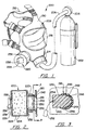
- the method can be accomplished, for example, by employing an emergency personal air filtering device with conventional fire fighter breathing equipment 200, such as the one shown in Figure 1.
- the apparatus includes a tank 202 of compressed air that is dispensed through a pressure regulator 204 into hose 206.
- the hose 206 extends from the regulator 204 to a face mask 208 which is formed by a rubber semi-hood 210 adapted to extend around the front portion of the fire fighter's head.
- the elastic material enables the semi-hood to stretch over and conform to the user's head creating an air tight seal therebetween. Straps 212 at the rear of the semi-hood aid in securing the face mask to the user's head.
- a clear plastic window 216 extends across a central opening in the semi-hood 210 in front of the fire fighter's face.
- the air hose 206 connects to a first port 214 at the chin area 215 of the face mask 208, thereby supplying air into the envelope formed by the mask.
- the face mask 208 also has a second port 218 for an emergency personal air filtering device 220.
- the second port 218 has tubular section 222 with external threads onto which an internally threaded outlet tube 223 of the filtering device 220 attaches, forming an air passage.
- the filtering device 220 can have or be connected to an adapter (not shown) for attaching to ports of different shapes and sizes.
- the emergency personal air filtering device 220 comprises a filter canister 224 of a conventional puck-type design, having an inlet opening 226 in a front surface 228 and an outlet opening 230 in a rear surface 232.
- a filter element 234 similar to filter element 134 previously described, is contained within the canister 224 to remove particles, such as smoke and hazardous vapors from the air passing through the canister.
- a self-adhesive cover 236 Prior to use a self-adhesive cover 236 is applied over the inlet opening 226 of the canister, thus providing an air-tight seal of that opening.
- a large tab 238 can be grasped by the fire fighter to pull the cover 236 off the filter canister 224 in order to use the air filtering device 220 in an emergency.
- the adhesive used will not permit the cover 236 to be reapplied over the inlet opening after the cover has been removed.
- use-evidencing tape that leaves a message bearing residue, color coding or the like, for example along the perimeter of the inlet opening, can be employed as the inlet opening cover 236.
- the air passage formed by the second port 218 of the face mask 208 also is closed prior to use of the emergency personal air filtering device 220.
- the second port 218 has a slot-like opening 240 on one side with a transverse internal groove 242 extending from this opening and across the interior of the second port.
- a plastic plate 244 is inserted into the groove 242 and snugly engages the groove to act as a valve member that provides an air-tight seal across the filtering device outlet. However, the plate is able to slide within the groove.
- the plate 244 has a pair of tabs 246 projecting from opposite sides into notches 248 in the side walls of the transverse groove 242 in the second port 218.
- the two tabs 246 are thinner than the main portion of the plate 244 and may have grooves cut along the interfaces between each tab and the main portion, enabling the tabs to break-away upon the fire fighter pulling on the plate to activate the air filtering device 220.
- a pull tab 252 is connected to the plate 244 by a wire 254 to aid the fire fighter in sliding the plate in an imminent life-threatening emergency.
- a lock tab 250 projects from a major surface of the plate 244 and prevents the plate from being removed from the second port 218.
- a piece of single use tape similar as character to the cover 238 may be applied between the plate 244 and the exterior surface of the face mask 208. This tape is pulled off either or both of the plate and the mask surface upon movement of the plate to open the second port 218. Alternatively, such tape could be adhered permanently to the plate and mask surface with the tape tearing upon movement of the plate to evidence use.
- the fire fighter receives air from the tank 202 through the first port of the face mask in Figure 1. Should the fire fighter be unable to exit a hazardous environment before the air in the tank is depleted, the person removes the cover 238 from the inlet opening of the emergency personal air filtering device 220 and pulls plate 244 to open the second port 218 on the mask. This action enables the fire fighter to access a back-up source of breathable air upon depletion of the air in tank 202 during an imminent life-threatening emergency.
- Both the cover 236 and the plate 244 provide mechanisms by which supervisory personnel can detect the use of the air filtering device and thereby the mechanisms discourage use in other than imminent life-threatening situations.
- these use indicating mechanism are employed to detect which masks require replacement of their filtering device upon the return to the fire fighter's quarters.
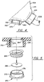
- exhalation port 260 under the chin area 215, for example.
- the exhalation port 260 is formed by a short tubular projection 262 that communicates with an aperture 264 through the underside of the chin area 215.
- An exhalation valve body 266 is inserted into the tubular projection 262 until butting a rim 274 around the aperture 264 and then an exhalation flapper valve 268 is inserted against the valve body 266.
- the exterior open end of the tubular projection 262 is closed valve cap 270 which has an ring 272 that enters the tubular projection 262 and holds the exhalation valve body 266 and exhalation flapper valve 268 against the rim 274 of mask aperture 264.
- a strip of adhesive tape 280 in Figure 4 is applied between the valve cap 270 and the body of the face mask 208 to maintain the cap in this position.
- the valve cap 270 has apertures 276 therethrough to allow exhaust air to escape from the mask, as will be described.
- the valve components 266 and 288 are compressed between the cap 270 and the face mask rim 274.
- the exhalation valve body 266 is biased by a constituent spring closing the exhalation port 260 when the fire fighter is inhaling air from the tank.
- the air pressure increase in the mask when the fire fighter exhales overcomes the force of the spring thereby opening the valve assembly to form an exhaust passage for the exhaled air.
- the fire fighter pulls the valve cap 270 downward, in addition to activating the emergency air filtering device 220 described previously.
- a retaining mechanism (not shown) prevents the cap from being pulled completely from the tubular projection 262. This action causes the tape 270 either to tear or peel away from the cap or mask thereby providing evidence that the exhalation port was placed in a state in which to use the emergency air filtering device 220. Movement of the cap 270 in this manner releases the bias of the spring in the exhalation valve body 266 and thus the compression of the valve components between the cap and the mask aperture rim 274. With the spring bias released, the exhalation flapper valve 268 controls the opening and closing of the exhalation port 260 as the fire fighter breathes.
Landscapes
- Health & Medical Sciences (AREA)
- General Health & Medical Sciences (AREA)
- Business, Economics & Management (AREA)
- Emergency Management (AREA)
- Pulmonology (AREA)
- Life Sciences & Earth Sciences (AREA)
- Zoology (AREA)
- Respiratory Apparatuses And Protective Means (AREA)
- Closures For Containers (AREA)
Abstract
Description
Claims (18)
- A self-contained breathing apparatus for smoke inhalation protection for emergency response personnel in imminently life-threatening situations and for encouraging its limited use to imminently life-threatening situations, said apparatus comprising:characterized in that said mask (208) has a second port (218) and the outlet opening (230) of the canister (224) communicates with said second port (218) of the mask (208).a mask (208) to be worn over the face of a fire fighter, and having a first port (214) connected to a hose (206) through which breathable air is supplied to the mask (208);a personal air filtering device (220) for smoke inhalation protection in imminent life-threatening situations upon depletion or failure of breathable air being supplied through the hose (206), said personal air filtering device (220) comprising a canister (224) having an inlet opening (226) through which air enters, an outlet opening (230) and a filter medium (234) within said canister (224) and through which air flows between the inlet opening (226) and the outlet opening (230); anda first use-evidencing mechanism (236, 238; 244, 246) closing one of the inlet opening (226) and the outlet opening (230) of said canister (224), and operatively coupled to the one of said canister (224) and said mask (208) to indicate use of the personal air filtering device (220),
- The self-contained breathing apparatus as recited in claim 1 wherein said first use-evidencing mechanism comprises a removable cover (236) applied over the inlet opening (226) in a manner which inhibits said cover (236) from being reapplied after removal.
- The self-contained breathing apparatus as recited in claim 1 wherein said first use-evidencing mechanism comprises a valve member (244) releasably closing the second port (218) of said face mask (208).
- The self-contained breathing apparatus as recited in claim 3 wherein said use-evidencing mechanism comprises a tab (246) extending from the valve member (244) and breakable therefrom upon use of the personal air filtering device (220).
- The self-contained breathing apparatus as recited in claim 1 further comprising a second use-evidencing mechanism (236, 238, 244, 246) closing the other of the inlet opening (226) and the outlet opening (230) of said canister (224), and operatively coupled to the other of said canister (224) and said mask (208) to indicate use of the personal air filtering device (220).
- The self-contained breathing apparatus as recited in claim 5 wherein said second use-evidencing mechanism comprises a valve member (244) releasably closing the second port (218) of said face mask (208).
- The self-contained breathing apparatus as recited in claim 1 wherein said mask (208) further comprises:an exhalation port (260) with a valve mechanism (266, 268, 270) having a first state when air is supplied to the mask (208) through the first port (214) and a second state when air is supplied to the mask through the second port (218); andanother use-evidencing mechanism (280) which indicates if the valve mechanism (266, 268, 270) of the exhalation port (260) has been placed into the second state.
- The self-contained breathing apparatus as recited in claim 1, wherein
said first use-evidencing mechanism closes the inlet opening (226) of said canister (224) and is operatively coupled to the canister (224) to indicate use of the personal air filtering device (220). - The self-contained breathing apparatus as recited in claim 8 wherein said first use-evidencing mechanism comprises a removable cover (236) applied over the inlet opening (226) in a manner which inhibits said cover (236) from being reapplied after removal.
- The self-contained breathing apparatus as recited in claim 8 further comprising a valve member (244) releasably sealing the second port (218) of said face mask (208).
- The self-contained breathing apparatus as recited in claim 10 further comprising a second use-evidencing mechanism (236, 238, 244, 246) operatively coupled to the valve member (244) to indicate use of the personal air filtering device (220).
- The self-contained breathing apparatus as recited in claim 11 wherein said second use-evidencing mechanism comprises a tab (246) extending from the valve member (244) and breakable therefrom upon use of the personal air filtering device (220).
- The self-contained breathing apparatus as recited in claim 8 wherein said mask (208) further comprises:an exhalation port (260) with a valve mechanism (266, 268, 270) having a first state when air is supplied to the mask (208) through the first port (214) and a second state when air is supplied to the mask (208) through the second port (218); andanother use-evidencing mechanism (280) which indicates if the valve mechanism (266, 268, 270) of the exhalation port (260) has been placed into the second state.
- A method for storing and preparing a self-contained breathing apparatus for smoke inhalation protection for emergency response personnel in imminently life-threatening situations and for encouraging its limited use to imminently life-threatening situations, said method comprising the steps of:configuring a smoke filter (234) in a use-evidencing manner so that employment of the smoke filter (234) for breathing is permanently indicated;attaching a conduit (206) between a first port (214) of a face mask (208) of the apparatus and a tank (202) of breathable air;attaching the smoke filter (234) to a second port (218) of the face mask (208) to filter air breathed by the fire fighter when the tank (202) of breathable air is depleted.
- The method as recited in claim 14 wherein the step of attaching the smoke filter (234) comprises releasably sealing the second port (218) with a use-evidencing mechanism (236, 238, 244, 246) operatively coupled to the second port (218) to indicate use of the smoke filter (234).
- The method as recited in claim 15 wherein the step of attaching the smoke filter (234) further comprises placing a releasable cover (236) over an inlet opening (226) of the smoke filter (234) wherein the releasable cover (236) includes a use-evidencing mechanism operatively coupled to indicate use of the smoke filter (234).
- The method as recited in claim 14 wherein the step of attaching the smoke filter (234) comprises placing a releasable cover (236) over an inlet opening (226) of the smoke filter (234) wherein the releasable cover (236) includes a use-evidencing mechanism operatively coupled to indicate use of the smoke filter (234).
- The second as recited in claim 14, wherein;
said fire fighter, when in a non-breathable environment, primarily uses said self-contained breathing apparatus to breathe air from said tank;
said fire fighter, upon depletion of air in the tank, activating the smoke filter as a source of breathable air wherein the activating involves breaching said use-evidencing mechanism to access said smoke filter, whereby use of said smoke filter is evidenced;
after exiting the non-breathable environment, a third party inspecting the use-evidencing mechanism; and
said fire fighter accounting for use of said smoke filter.
Applications Claiming Priority (3)
| Application Number | Priority Date | Filing Date | Title |
|---|---|---|---|
| US08/652,664 US5964218A (en) | 1994-08-31 | 1996-05-28 | Face mask with back-up smoke inhalation protection and method of operation |
| US652664 | 1996-05-28 | ||
| PCT/US1997/008824 WO1997045154A1 (en) | 1996-05-28 | 1997-05-27 | Face mask with back-up smoke inhalation protection and method of operation |
Publications (3)
| Publication Number | Publication Date |
|---|---|
| EP0956067A1 EP0956067A1 (en) | 1999-11-17 |
| EP0956067A4 EP0956067A4 (en) | 2001-07-18 |
| EP0956067B1 true EP0956067B1 (en) | 2004-07-21 |
Family
ID=24617667
Family Applications (1)
| Application Number | Title | Priority Date | Filing Date |
|---|---|---|---|
| EP97926712A Expired - Lifetime EP0956067B1 (en) | 1996-05-28 | 1997-05-27 | Face mask with back-up smoke inhalation protection and method of operation |
Country Status (13)
| Country | Link |
|---|---|
| US (2) | US5964218A (en) |
| EP (1) | EP0956067B1 (en) |
| JP (1) | JP2000511088A (en) |
| KR (1) | KR20000016090A (en) |
| CN (1) | CN1121885C (en) |
| AT (1) | ATE271401T1 (en) |
| AU (1) | AU3141597A (en) |
| BR (1) | BR9709609A (en) |
| CA (1) | CA2257092A1 (en) |
| DE (1) | DE69729957T2 (en) |
| PL (1) | PL330712A1 (en) |
| RU (1) | RU2183485C2 (en) |
| WO (1) | WO1997045154A1 (en) |
Families Citing this family (35)
| Publication number | Priority date | Publication date | Assignee | Title |
|---|---|---|---|---|
| US5964218A (en) * | 1994-08-31 | 1999-10-12 | Lifepro, Inc. | Face mask with back-up smoke inhalation protection and method of operation |
| US6626178B2 (en) * | 2001-01-12 | 2003-09-30 | Kirby Morgan Dive Systems, Inc. | Full face mask with face seal and removable adaptors allowing full access to separate spaces |
| US6553989B1 (en) | 2001-07-20 | 2003-04-29 | James M. Richardson | Self-contained breathing apparatus with emergency filtration device |
| US6701925B1 (en) | 2002-04-11 | 2004-03-09 | Todd A. Resnick | Protective hood respirator |
| US6761162B1 (en) * | 2002-12-23 | 2004-07-13 | Brookdale International Systems, Inc. | Personal disposable emergency breathing system with radial flow |
| US20060048777A1 (en) * | 2003-03-21 | 2006-03-09 | Interspiro, Inc. | Apparatus and method for providing breathable air and bodily protection in a contaminated environment |
| US20040182394A1 (en) * | 2003-03-21 | 2004-09-23 | Alvey Jeffrey Arthur | Powered air purifying respirator system and self contained breathing apparatus |
| US7647927B2 (en) | 2003-08-22 | 2010-01-19 | Wilcox Industries Corp. | Self-contained breathing system |
| US7296575B1 (en) * | 2003-12-05 | 2007-11-20 | Ric Investments, Llc | Headgear and interface assembly using same |
| USD538649S1 (en) * | 2003-12-08 | 2007-03-20 | Glaxo Group Limited | Dispensing attachment for dispensing unit products, for instance pills |
| US20060096597A1 (en) * | 2004-11-09 | 2006-05-11 | Home Health Medical Equipment Incorporated, D/B/A Ag Industries | Swivel filter for use with sleep apnea and other respiratory equipment including associated interface systems |
| NZ565507A (en) | 2005-10-14 | 2011-06-30 | Resmed Ltd | Mask with cushion having lip which in use deflects against frame of mask |
| ES2954589T3 (en) | 2006-07-14 | 2023-11-23 | Fisher & Paykel Healthcare Ltd | Respiratory assistance device |
| BRPI0716242A2 (en) * | 2006-08-29 | 2013-08-13 | Avox Systems Inc | adapter for use with a filter container, and breathing apparatus for mounting on a user's body |
| DE102007050369B4 (en) * | 2006-10-24 | 2025-08-21 | Löwenstein Medical Technology S.A. | Banded holding device for ventilation masks |
| US8517023B2 (en) | 2007-01-30 | 2013-08-27 | Resmed Limited | Mask system with interchangeable headgear connectors |
| US11331447B2 (en) | 2008-03-04 | 2022-05-17 | ResMed Pty Ltd | Mask system with snap-fit shroud |
| DE202009018870U1 (en) | 2008-03-04 | 2014-02-03 | Resmed Ltd. | mask system |
| US10792451B2 (en) * | 2008-05-12 | 2020-10-06 | Fisher & Paykel Healthcare Limited | Patient interface and aspects thereof |
| US11660413B2 (en) | 2008-07-18 | 2023-05-30 | Fisher & Paykel Healthcare Limited | Breathing assistance apparatus |
| FR2941624B1 (en) * | 2009-02-05 | 2012-05-18 | Materiels Ind De Securite | DEVICE FOR PROTECTING A PERSON AND CORRESPONDING PROTECTION ASSEMBLY. |
| EP4640259A3 (en) | 2010-10-08 | 2025-11-12 | Fisher & Paykel Healthcare Limited | Mask seal assembly |
| US9993604B2 (en) | 2012-04-27 | 2018-06-12 | Covidien Lp | Methods and systems for an optimized proportional assist ventilation |
| US10362967B2 (en) | 2012-07-09 | 2019-07-30 | Covidien Lp | Systems and methods for missed breath detection and indication |
| US9027552B2 (en) | 2012-07-31 | 2015-05-12 | Covidien Lp | Ventilator-initiated prompt or setting regarding detection of asynchrony during ventilation |
| KR101301444B1 (en) * | 2013-01-16 | 2013-08-28 | 주식회사 산청 | Canister fixing unit for hood type gas mask |
| US9597532B2 (en) | 2013-06-07 | 2017-03-21 | Tda Research, Inc. | Breathing apparatus, and method for controlling temperature fluctuations |
| US9950129B2 (en) | 2014-10-27 | 2018-04-24 | Covidien Lp | Ventilation triggering using change-point detection |
| CN107847773A (en) * | 2015-08-03 | 2018-03-27 | 曼·胡默尔有限公司 | Filter cartridges and respirators for respirators |
| JP6128474B1 (en) * | 2016-07-06 | 2017-05-17 | 正泰 増茂 | Full-face mask type air purifier and method for manufacturing full-face mask type air purifier |
| CN106943687A (en) * | 2017-05-11 | 2017-07-14 | 北京花兰德科技咨询服务有限公司 | Fireman's emergency self-saving device |
| JP7193129B2 (en) | 2019-01-29 | 2022-12-20 | 株式会社ホシモト | door handle |
| US11324954B2 (en) | 2019-06-28 | 2022-05-10 | Covidien Lp | Achieving smooth breathing by modified bilateral phrenic nerve pacing |
| KR102147827B1 (en) * | 2019-11-14 | 2020-08-25 | 손창오 | Welding mask |
| CN111359116A (en) * | 2020-04-02 | 2020-07-03 | 丁志国 | Hood device for biological protection |
Family Cites Families (43)
| Publication number | Priority date | Publication date | Assignee | Title |
|---|---|---|---|---|
| US1537519A (en) * | 1924-12-05 | 1925-05-12 | Yablick Max | Indicating gas-mask canister |
| US2450610A (en) * | 1944-01-08 | 1948-10-05 | Edwin G Pierce | Air filter |
| US2610624A (en) * | 1947-06-04 | 1952-09-16 | Mine Safety Appliances Co | Pocket respirator |
| DE1434909A1 (en) * | 1963-07-18 | 1968-10-31 | Draegerwerk Ag | Carbon monoxide filter self-rescuer |
| DE1282469B (en) * | 1966-04-30 | 1968-11-07 | Draegerwerk Ag | Gas-tight container under vacuum for breathing apparatus and method for closing such a container |
| US3653581A (en) * | 1968-04-10 | 1972-04-04 | Continental Can Co | Hermetic packaging with plastic container |
| US3731678A (en) * | 1971-03-05 | 1973-05-08 | Phyllis Pyzel | Smoke inhalation protector |
| FR2211854A5 (en) * | 1972-12-22 | 1974-07-19 | Draegerwerk Ag | |
| DE2542460A1 (en) * | 1975-09-24 | 1977-04-07 | Draegerwerk Ag | BREATHING FILTER WITH SEAL LOCK |
| DE2609034B2 (en) * | 1976-03-05 | 1981-04-30 | Drägerwerk AG, 2400 Lübeck | Connection for breathing apparatus |
| DE2639545C3 (en) * | 1976-09-02 | 1979-04-05 | Draegerwerk Ag, 2400 Luebeck | Escape filter device with protective hood |
| US4155358A (en) * | 1976-12-13 | 1979-05-22 | Minnesota Mining And Manufacturing Company | Respirator |
| US4276982A (en) * | 1977-10-26 | 1981-07-07 | Arvey Corporation | Pressure sensitive tape closure pouch |
| US4154586A (en) * | 1978-01-13 | 1979-05-15 | American Optical Corporation | Respirator cartridge end-of-service lift indicator system and method of making |
| DE2926728A1 (en) * | 1979-07-03 | 1981-02-26 | Draegerwerk Ag | Humidity-sensitive filter storage vacuum container - has sealing ring with slit along entire container circumference |
| DE2948423C2 (en) * | 1979-12-01 | 1982-12-09 | Drägerwerk AG, 2400 Lübeck | Escape filter device with protective hood |
| DE3206483C2 (en) * | 1982-02-23 | 1984-10-18 | Drägerwerk AG, 2400 Lübeck | Filter breathing apparatus with a canister |
| DE3206484C2 (en) * | 1982-02-23 | 1984-03-15 | Drägerwerk AG, 2400 Lübeck | Breathing apparatus with protective hood |
| US4488547A (en) * | 1982-09-07 | 1984-12-18 | Kenneth R. Bowers, Jr. | Face mask |
| DE3236028C2 (en) * | 1982-09-29 | 1984-07-19 | Drägerwerk AG, 2400 Lübeck | Escape filter device with a breathing filter in a half mask |
| US4475661A (en) * | 1982-12-03 | 1984-10-09 | Griffin Robert B | Tamper-indicating container assembly |
| GB8308303D0 (en) * | 1983-03-25 | 1983-05-05 | Smiths Bros Whitehaven Ltd | Pouches |
| DE3405098A1 (en) * | 1984-02-14 | 1985-08-29 | Drägerwerk AG, 2400 Lübeck | CARBON OXYGEN RESPIRATOR |
| US4541541A (en) * | 1984-10-09 | 1985-09-17 | Weatherchem Corporation | Tamper-resistant closure for dispensers |
| US4613063A (en) * | 1985-01-07 | 1986-09-23 | Sunbeam Plastics Corporation | Dispensing package |
| DE3507486C2 (en) * | 1985-03-02 | 1987-01-02 | Drägerwerk AG, 2400 Lübeck | Carbon monoxide breathing air filter |
| GB8524181D0 (en) * | 1985-10-01 | 1985-11-06 | Stewart J S S | Breathing equipment |
| US4726365A (en) * | 1986-05-09 | 1988-02-23 | Richard Jablonski | Air filtering apparatus |
| US4934361A (en) * | 1986-10-20 | 1990-06-19 | Wgm Safety Corp. | Respirator |
| US4745730A (en) * | 1986-10-22 | 1988-05-24 | Bartle Sr David C | Method and apparatus for evacuating air from food containers |
| DE3721662A1 (en) * | 1987-06-26 | 1989-01-12 | Auergesellschaft Gmbh | PROTECTIVE HELMET WITH A STRAPLESS RESPIRATOR |
| US4818120A (en) * | 1987-07-20 | 1989-04-04 | Nabisco Brands, Inc. | Openable and reclosable tamper evident bag tag |
| AU616689B2 (en) * | 1987-10-30 | 1991-11-07 | Divelink Pty. Ltd. | Pressure compensated communication system |
| GB2223683B (en) * | 1988-10-14 | 1992-02-12 | Sabre Safety Ltd | Respirator assembly and method of assembling a respirator in a metal housing |
| DE3907706A1 (en) * | 1989-01-25 | 1990-10-11 | Draegerwerk Ag | GAS-TIGHT PACKAGING WITH A SECURING DEVICE |
| US5291880A (en) * | 1990-08-16 | 1994-03-08 | Cairns & Brother Inc. | Protective helmet with protective facepiece connection and adjustment provision |
| US5186165A (en) * | 1991-06-05 | 1993-02-16 | Brookdale International Systems Inc. | Filtering canister with deployable hood and mouthpiece |
| DE4220780C1 (en) * | 1992-06-25 | 1993-09-23 | Draegerwerk Ag, 23558 Luebeck, De | |
| US5303850A (en) * | 1992-07-23 | 1994-04-19 | Colgate-Palmolive Company | Dispensing cap |
| US5562092A (en) * | 1993-06-14 | 1996-10-08 | George; Eric W. | Firefighter's emergency smoke filter |
| US5449085A (en) * | 1994-03-14 | 1995-09-12 | Electra Form, Inc. | Recyclable container and rotatable closure of plastics material |
| TW287952B (en) * | 1994-08-31 | 1996-10-11 | Lifepro Inc | |
| US5964218A (en) * | 1994-08-31 | 1999-10-12 | Lifepro, Inc. | Face mask with back-up smoke inhalation protection and method of operation |
-
1996
- 1996-05-28 US US08/652,664 patent/US5964218A/en not_active Expired - Fee Related
-
1997
- 1997-05-27 CN CN97195067A patent/CN1121885C/en not_active Expired - Fee Related
- 1997-05-27 AU AU31415/97A patent/AU3141597A/en not_active Abandoned
- 1997-05-27 RU RU98123197/12A patent/RU2183485C2/en active
- 1997-05-27 JP JP09542797A patent/JP2000511088A/en not_active Ceased
- 1997-05-27 CA CA002257092A patent/CA2257092A1/en not_active Abandoned
- 1997-05-27 BR BR9709609A patent/BR9709609A/en not_active IP Right Cessation
- 1997-05-27 AT AT97926712T patent/ATE271401T1/en not_active IP Right Cessation
- 1997-05-27 KR KR1019980709657A patent/KR20000016090A/en not_active Abandoned
- 1997-05-27 EP EP97926712A patent/EP0956067B1/en not_active Expired - Lifetime
- 1997-05-27 PL PL97330712A patent/PL330712A1/en unknown
- 1997-05-27 WO PCT/US1997/008824 patent/WO1997045154A1/en not_active Ceased
- 1997-05-27 DE DE69729957T patent/DE69729957T2/en not_active Expired - Fee Related
-
1999
- 1999-01-08 US US09/227,779 patent/US6308851B1/en not_active Expired - Fee Related
Also Published As
| Publication number | Publication date |
|---|---|
| DE69729957T2 (en) | 2005-08-25 |
| DE69729957D1 (en) | 2004-08-26 |
| US5964218A (en) | 1999-10-12 |
| JP2000511088A (en) | 2000-08-29 |
| CN1219883A (en) | 1999-06-16 |
| EP0956067A1 (en) | 1999-11-17 |
| RU2183485C2 (en) | 2002-06-20 |
| WO1997045154A1 (en) | 1997-12-04 |
| ATE271401T1 (en) | 2004-08-15 |
| HK1021147A1 (en) | 2000-06-02 |
| CN1121885C (en) | 2003-09-24 |
| AU3141597A (en) | 1998-01-05 |
| PL330712A1 (en) | 1999-05-24 |
| CA2257092A1 (en) | 1997-12-04 |
| EP0956067A4 (en) | 2001-07-18 |
| BR9709609A (en) | 1999-08-10 |
| US6308851B1 (en) | 2001-10-30 |
| KR20000016090A (en) | 2000-03-25 |
Similar Documents
| Publication | Publication Date | Title |
|---|---|---|
| US5964218A (en) | Face mask with back-up smoke inhalation protection and method of operation | |
| EP0781156B1 (en) | Method of air filtration for fire fighter emergency smoke inhalation protection | |
| MXPA97001534A (en) | Process and emergency system for the protection of inhalation of h | |
| US6340024B1 (en) | Protective hood and oral/nasal mask | |
| EP0847296B1 (en) | Personal emergency breathing system for supplied air respirators | |
| US5562092A (en) | Firefighter's emergency smoke filter | |
| KR102600723B1 (en) | Gas Mask For Opening Easily Closure Cap Of Canister | |
| KR102000336B1 (en) | Mask package for emergency evacuation and using method thereof | |
| GB2209123A (en) | Breathing apparatus | |
| AU756621B2 (en) | Face mask with back-up smoke inhalation protection and method of operation | |
| MXPA98009977A (en) | Mask for the face with backing protection against inhalation of smoke, and method of operation | |
| HK1021147B (en) | Face mask with back-up smoke inhalation protection and method of operation | |
| CN111632294A (en) | Mask with air bypass valve and air supply breathing device using same | |
| EP0956100B1 (en) | Breathing equipment |
Legal Events
| Date | Code | Title | Description |
|---|---|---|---|
| PUAI | Public reference made under article 153(3) epc to a published international application that has entered the european phase |
Free format text: ORIGINAL CODE: 0009012 |
|
| 17P | Request for examination filed |
Effective date: 19981210 |
|
| AK | Designated contracting states |
Kind code of ref document: A1 Designated state(s): AT BE CH DE DK ES FI FR GB GR IE IT LI LU MC NL PT SE |
|
| A4 | Supplementary search report drawn up and despatched |
Effective date: 20010531 |
|
| AK | Designated contracting states |
Kind code of ref document: A4 Designated state(s): AT BE CH DE DK ES FI FR GB GR IE IT LI LU MC NL PT SE |
|
| RIC1 | Information provided on ipc code assigned before grant |
Free format text: 7A 61M 16/00 A, 7A 62B 7/00 B, 7A 62B 7/10 B, 7A 62B 19/00 B, 7A 62B 23/02 B |
|
| 17Q | First examination report despatched |
Effective date: 20030210 |
|
| GRAP | Despatch of communication of intention to grant a patent |
Free format text: ORIGINAL CODE: EPIDOSNIGR1 |
|
| GRAS | Grant fee paid |
Free format text: ORIGINAL CODE: EPIDOSNIGR3 |
|
| GRAA | (expected) grant |
Free format text: ORIGINAL CODE: 0009210 |
|
| AK | Designated contracting states |
Kind code of ref document: B1 Designated state(s): AT BE CH DE DK ES FI FR GB GR IE IT LI LU MC NL PT SE |
|
| PG25 | Lapsed in a contracting state [announced via postgrant information from national office to epo] |
Ref country code: NL Free format text: LAPSE BECAUSE OF FAILURE TO SUBMIT A TRANSLATION OF THE DESCRIPTION OR TO PAY THE FEE WITHIN THE PRESCRIBED TIME-LIMIT Effective date: 20040721 Ref country code: LI Free format text: LAPSE BECAUSE OF FAILURE TO SUBMIT A TRANSLATION OF THE DESCRIPTION OR TO PAY THE FEE WITHIN THE PRESCRIBED TIME-LIMIT Effective date: 20040721 Ref country code: IT Free format text: LAPSE BECAUSE OF FAILURE TO SUBMIT A TRANSLATION OF THE DESCRIPTION OR TO PAY THE FEE WITHIN THE PRESCRIBED TIME-LIMIT;WARNING: LAPSES OF ITALIAN PATENTS WITH EFFECTIVE DATE BEFORE 2007 MAY HAVE OCCURRED AT ANY TIME BEFORE 2007. THE CORRECT EFFECTIVE DATE MAY BE DIFFERENT FROM THE ONE RECORDED. Effective date: 20040721 Ref country code: FI Free format text: LAPSE BECAUSE OF FAILURE TO SUBMIT A TRANSLATION OF THE DESCRIPTION OR TO PAY THE FEE WITHIN THE PRESCRIBED TIME-LIMIT Effective date: 20040721 Ref country code: CH Free format text: LAPSE BECAUSE OF FAILURE TO SUBMIT A TRANSLATION OF THE DESCRIPTION OR TO PAY THE FEE WITHIN THE PRESCRIBED TIME-LIMIT Effective date: 20040721 Ref country code: BE Free format text: LAPSE BECAUSE OF FAILURE TO SUBMIT A TRANSLATION OF THE DESCRIPTION OR TO PAY THE FEE WITHIN THE PRESCRIBED TIME-LIMIT Effective date: 20040721 Ref country code: AT Free format text: LAPSE BECAUSE OF FAILURE TO SUBMIT A TRANSLATION OF THE DESCRIPTION OR TO PAY THE FEE WITHIN THE PRESCRIBED TIME-LIMIT Effective date: 20040721 |
|
| REG | Reference to a national code |
Ref country code: GB Ref legal event code: FG4D |
|
| REG | Reference to a national code |
Ref country code: CH Ref legal event code: EP |
|
| REG | Reference to a national code |
Ref country code: IE Ref legal event code: FG4D |
|
| REF | Corresponds to: |
Ref document number: 69729957 Country of ref document: DE Date of ref document: 20040826 Kind code of ref document: P |
|
| PG25 | Lapsed in a contracting state [announced via postgrant information from national office to epo] |
Ref country code: SE Free format text: LAPSE BECAUSE OF FAILURE TO SUBMIT A TRANSLATION OF THE DESCRIPTION OR TO PAY THE FEE WITHIN THE PRESCRIBED TIME-LIMIT Effective date: 20041021 Ref country code: GR Free format text: LAPSE BECAUSE OF FAILURE TO SUBMIT A TRANSLATION OF THE DESCRIPTION OR TO PAY THE FEE WITHIN THE PRESCRIBED TIME-LIMIT Effective date: 20041021 Ref country code: DK Free format text: LAPSE BECAUSE OF FAILURE TO SUBMIT A TRANSLATION OF THE DESCRIPTION OR TO PAY THE FEE WITHIN THE PRESCRIBED TIME-LIMIT Effective date: 20041021 |
|
| PG25 | Lapsed in a contracting state [announced via postgrant information from national office to epo] |
Ref country code: ES Free format text: LAPSE BECAUSE OF FAILURE TO SUBMIT A TRANSLATION OF THE DESCRIPTION OR TO PAY THE FEE WITHIN THE PRESCRIBED TIME-LIMIT Effective date: 20041101 |
|
| NLV1 | Nl: lapsed or annulled due to failure to fulfill the requirements of art. 29p and 29m of the patents act | ||
| REG | Reference to a national code |
Ref country code: CH Ref legal event code: PL |
|
| ET | Fr: translation filed | ||
| PG25 | Lapsed in a contracting state [announced via postgrant information from national office to epo] |
Ref country code: LU Free format text: LAPSE BECAUSE OF NON-PAYMENT OF DUE FEES Effective date: 20050527 Ref country code: IE Free format text: LAPSE BECAUSE OF NON-PAYMENT OF DUE FEES Effective date: 20050527 Ref country code: GB Free format text: LAPSE BECAUSE OF NON-PAYMENT OF DUE FEES Effective date: 20050527 |
|
| PLBE | No opposition filed within time limit |
Free format text: ORIGINAL CODE: 0009261 |
|
| STAA | Information on the status of an ep patent application or granted ep patent |
Free format text: STATUS: NO OPPOSITION FILED WITHIN TIME LIMIT |
|
| PG25 | Lapsed in a contracting state [announced via postgrant information from national office to epo] |
Ref country code: MC Free format text: LAPSE BECAUSE OF NON-PAYMENT OF DUE FEES Effective date: 20050531 |
|
| 26N | No opposition filed |
Effective date: 20050422 |
|
| PG25 | Lapsed in a contracting state [announced via postgrant information from national office to epo] |
Ref country code: DE Free format text: LAPSE BECAUSE OF NON-PAYMENT OF DUE FEES Effective date: 20051201 |
|
| GBPC | Gb: european patent ceased through non-payment of renewal fee |
Effective date: 20050527 |
|
| PG25 | Lapsed in a contracting state [announced via postgrant information from national office to epo] |
Ref country code: FR Free format text: LAPSE BECAUSE OF NON-PAYMENT OF DUE FEES Effective date: 20060131 |
|
| REG | Reference to a national code |
Ref country code: IE Ref legal event code: MM4A |
|
| REG | Reference to a national code |
Ref country code: FR Ref legal event code: ST Effective date: 20060131 |
|
| PG25 | Lapsed in a contracting state [announced via postgrant information from national office to epo] |
Ref country code: PT Free format text: LAPSE BECAUSE OF NON-PAYMENT OF DUE FEES Effective date: 20041221 |