EP0955962B1 - Knee mechanism for an artificial limb - Google Patents
Knee mechanism for an artificial limb Download PDFInfo
- Publication number
- EP0955962B1 EP0955962B1 EP97908970A EP97908970A EP0955962B1 EP 0955962 B1 EP0955962 B1 EP 0955962B1 EP 97908970 A EP97908970 A EP 97908970A EP 97908970 A EP97908970 A EP 97908970A EP 0955962 B1 EP0955962 B1 EP 0955962B1
- Authority
- EP
- European Patent Office
- Prior art keywords
- crank
- lower member
- knee mechanism
- upper member
- slider
- Prior art date
- Legal status (The legal status is an assumption and is not a legal conclusion. Google has not performed a legal analysis and makes no representation as to the accuracy of the status listed.)
- Expired - Lifetime
Links
- 230000007246 mechanism Effects 0.000 title claims abstract description 42
- 210000003127 knee Anatomy 0.000 title claims abstract description 41
- 210000003414 extremity Anatomy 0.000 title description 3
- 210000003141 lower extremity Anatomy 0.000 claims abstract description 7
- 210000000689 upper leg Anatomy 0.000 claims abstract description 6
- 238000005096 rolling process Methods 0.000 abstract description 2
- 230000000717 retained effect Effects 0.000 description 2
- 210000000629 knee joint Anatomy 0.000 description 1
- 230000004048 modification Effects 0.000 description 1
- 238000012986 modification Methods 0.000 description 1
- NJPPVKZQTLUDBO-UHFFFAOYSA-N novaluron Chemical compound C1=C(Cl)C(OC(F)(F)C(OC(F)(F)F)F)=CC=C1NC(=O)NC(=O)C1=C(F)C=CC=C1F NJPPVKZQTLUDBO-UHFFFAOYSA-N 0.000 description 1
- 230000002093 peripheral effect Effects 0.000 description 1
Images



Classifications
-
- A—HUMAN NECESSITIES
- A61—MEDICAL OR VETERINARY SCIENCE; HYGIENE
- A61F—FILTERS IMPLANTABLE INTO BLOOD VESSELS; PROSTHESES; DEVICES PROVIDING PATENCY TO, OR PREVENTING COLLAPSING OF, TUBULAR STRUCTURES OF THE BODY, e.g. STENTS; ORTHOPAEDIC, NURSING OR CONTRACEPTIVE DEVICES; FOMENTATION; TREATMENT OR PROTECTION OF EYES OR EARS; BANDAGES, DRESSINGS OR ABSORBENT PADS; FIRST-AID KITS
- A61F2/00—Filters implantable into blood vessels; Prostheses, i.e. artificial substitutes or replacements for parts of the body; Appliances for connecting them with the body; Devices providing patency to, or preventing collapsing of, tubular structures of the body, e.g. stents
- A61F2/50—Prostheses not implantable in the body
- A61F2/60—Artificial legs or feet or parts thereof
- A61F2/64—Knee joints
- A61F2/642—Polycentric joints, without longitudinal rotation
-
- A—HUMAN NECESSITIES
- A61—MEDICAL OR VETERINARY SCIENCE; HYGIENE
- A61F—FILTERS IMPLANTABLE INTO BLOOD VESSELS; PROSTHESES; DEVICES PROVIDING PATENCY TO, OR PREVENTING COLLAPSING OF, TUBULAR STRUCTURES OF THE BODY, e.g. STENTS; ORTHOPAEDIC, NURSING OR CONTRACEPTIVE DEVICES; FOMENTATION; TREATMENT OR PROTECTION OF EYES OR EARS; BANDAGES, DRESSINGS OR ABSORBENT PADS; FIRST-AID KITS
- A61F2/00—Filters implantable into blood vessels; Prostheses, i.e. artificial substitutes or replacements for parts of the body; Appliances for connecting them with the body; Devices providing patency to, or preventing collapsing of, tubular structures of the body, e.g. stents
- A61F2/50—Prostheses not implantable in the body
- A61F2/60—Artificial legs or feet or parts thereof
- A61F2/64—Knee joints
- A61F2/642—Polycentric joints, without longitudinal rotation
- A61F2/644—Polycentric joints, without longitudinal rotation of the single-bar or multi-bar linkage type
-
- A—HUMAN NECESSITIES
- A61—MEDICAL OR VETERINARY SCIENCE; HYGIENE
- A61F—FILTERS IMPLANTABLE INTO BLOOD VESSELS; PROSTHESES; DEVICES PROVIDING PATENCY TO, OR PREVENTING COLLAPSING OF, TUBULAR STRUCTURES OF THE BODY, e.g. STENTS; ORTHOPAEDIC, NURSING OR CONTRACEPTIVE DEVICES; FOMENTATION; TREATMENT OR PROTECTION OF EYES OR EARS; BANDAGES, DRESSINGS OR ABSORBENT PADS; FIRST-AID KITS
- A61F2/00—Filters implantable into blood vessels; Prostheses, i.e. artificial substitutes or replacements for parts of the body; Appliances for connecting them with the body; Devices providing patency to, or preventing collapsing of, tubular structures of the body, e.g. stents
- A61F2/50—Prostheses not implantable in the body
- A61F2/60—Artificial legs or feet or parts thereof
- A61F2/64—Knee joints
- A61F2/642—Polycentric joints, without longitudinal rotation
- A61F2/646—Polycentric joints, without longitudinal rotation of the pin-guiding groove linkage type
-
- A—HUMAN NECESSITIES
- A61—MEDICAL OR VETERINARY SCIENCE; HYGIENE
- A61F—FILTERS IMPLANTABLE INTO BLOOD VESSELS; PROSTHESES; DEVICES PROVIDING PATENCY TO, OR PREVENTING COLLAPSING OF, TUBULAR STRUCTURES OF THE BODY, e.g. STENTS; ORTHOPAEDIC, NURSING OR CONTRACEPTIVE DEVICES; FOMENTATION; TREATMENT OR PROTECTION OF EYES OR EARS; BANDAGES, DRESSINGS OR ABSORBENT PADS; FIRST-AID KITS
- A61F2/00—Filters implantable into blood vessels; Prostheses, i.e. artificial substitutes or replacements for parts of the body; Appliances for connecting them with the body; Devices providing patency to, or preventing collapsing of, tubular structures of the body, e.g. stents
- A61F2/50—Prostheses not implantable in the body
- A61F2/76—Means for assembling, fitting or testing prostheses, e.g. for measuring or balancing, e.g. alignment means
-
- A—HUMAN NECESSITIES
- A61—MEDICAL OR VETERINARY SCIENCE; HYGIENE
- A61F—FILTERS IMPLANTABLE INTO BLOOD VESSELS; PROSTHESES; DEVICES PROVIDING PATENCY TO, OR PREVENTING COLLAPSING OF, TUBULAR STRUCTURES OF THE BODY, e.g. STENTS; ORTHOPAEDIC, NURSING OR CONTRACEPTIVE DEVICES; FOMENTATION; TREATMENT OR PROTECTION OF EYES OR EARS; BANDAGES, DRESSINGS OR ABSORBENT PADS; FIRST-AID KITS
- A61F2/00—Filters implantable into blood vessels; Prostheses, i.e. artificial substitutes or replacements for parts of the body; Appliances for connecting them with the body; Devices providing patency to, or preventing collapsing of, tubular structures of the body, e.g. stents
- A61F2/02—Prostheses implantable into the body
- A61F2/30—Joints
- A61F2002/30001—Additional features of subject-matter classified in A61F2/28, A61F2/30 and subgroups thereof
- A61F2002/30108—Shapes
- A61F2002/3011—Cross-sections or two-dimensional shapes
- A61F2002/30138—Convex polygonal shapes
- A61F2002/30153—Convex polygonal shapes rectangular
-
- A—HUMAN NECESSITIES
- A61—MEDICAL OR VETERINARY SCIENCE; HYGIENE
- A61F—FILTERS IMPLANTABLE INTO BLOOD VESSELS; PROSTHESES; DEVICES PROVIDING PATENCY TO, OR PREVENTING COLLAPSING OF, TUBULAR STRUCTURES OF THE BODY, e.g. STENTS; ORTHOPAEDIC, NURSING OR CONTRACEPTIVE DEVICES; FOMENTATION; TREATMENT OR PROTECTION OF EYES OR EARS; BANDAGES, DRESSINGS OR ABSORBENT PADS; FIRST-AID KITS
- A61F2/00—Filters implantable into blood vessels; Prostheses, i.e. artificial substitutes or replacements for parts of the body; Appliances for connecting them with the body; Devices providing patency to, or preventing collapsing of, tubular structures of the body, e.g. stents
- A61F2/02—Prostheses implantable into the body
- A61F2/30—Joints
- A61F2002/30001—Additional features of subject-matter classified in A61F2/28, A61F2/30 and subgroups thereof
- A61F2002/30108—Shapes
- A61F2002/3011—Cross-sections or two-dimensional shapes
- A61F2002/30159—Concave polygonal shapes
- A61F2002/30166—H-shaped or I-shaped
-
- A—HUMAN NECESSITIES
- A61—MEDICAL OR VETERINARY SCIENCE; HYGIENE
- A61F—FILTERS IMPLANTABLE INTO BLOOD VESSELS; PROSTHESES; DEVICES PROVIDING PATENCY TO, OR PREVENTING COLLAPSING OF, TUBULAR STRUCTURES OF THE BODY, e.g. STENTS; ORTHOPAEDIC, NURSING OR CONTRACEPTIVE DEVICES; FOMENTATION; TREATMENT OR PROTECTION OF EYES OR EARS; BANDAGES, DRESSINGS OR ABSORBENT PADS; FIRST-AID KITS
- A61F2/00—Filters implantable into blood vessels; Prostheses, i.e. artificial substitutes or replacements for parts of the body; Appliances for connecting them with the body; Devices providing patency to, or preventing collapsing of, tubular structures of the body, e.g. stents
- A61F2/02—Prostheses implantable into the body
- A61F2/30—Joints
- A61F2002/30001—Additional features of subject-matter classified in A61F2/28, A61F2/30 and subgroups thereof
- A61F2002/30316—The prosthesis having different structural features at different locations within the same prosthesis; Connections between prosthetic parts; Special structural features of bone or joint prostheses not otherwise provided for
- A61F2002/30329—Connections or couplings between prosthetic parts, e.g. between modular parts; Connecting elements
- A61F2002/30331—Connections or couplings between prosthetic parts, e.g. between modular parts; Connecting elements made by longitudinally pushing a protrusion into a complementarily-shaped recess, e.g. held by friction fit
- A61F2002/30354—Cylindrically-shaped protrusion and recess, e.g. cylinder of circular basis
-
- A—HUMAN NECESSITIES
- A61—MEDICAL OR VETERINARY SCIENCE; HYGIENE
- A61F—FILTERS IMPLANTABLE INTO BLOOD VESSELS; PROSTHESES; DEVICES PROVIDING PATENCY TO, OR PREVENTING COLLAPSING OF, TUBULAR STRUCTURES OF THE BODY, e.g. STENTS; ORTHOPAEDIC, NURSING OR CONTRACEPTIVE DEVICES; FOMENTATION; TREATMENT OR PROTECTION OF EYES OR EARS; BANDAGES, DRESSINGS OR ABSORBENT PADS; FIRST-AID KITS
- A61F2/00—Filters implantable into blood vessels; Prostheses, i.e. artificial substitutes or replacements for parts of the body; Appliances for connecting them with the body; Devices providing patency to, or preventing collapsing of, tubular structures of the body, e.g. stents
- A61F2/02—Prostheses implantable into the body
- A61F2/30—Joints
- A61F2002/30001—Additional features of subject-matter classified in A61F2/28, A61F2/30 and subgroups thereof
- A61F2002/30316—The prosthesis having different structural features at different locations within the same prosthesis; Connections between prosthetic parts; Special structural features of bone or joint prostheses not otherwise provided for
- A61F2002/30329—Connections or couplings between prosthetic parts, e.g. between modular parts; Connecting elements
- A61F2002/30331—Connections or couplings between prosthetic parts, e.g. between modular parts; Connecting elements made by longitudinally pushing a protrusion into a complementarily-shaped recess, e.g. held by friction fit
- A61F2002/30362—Connections or couplings between prosthetic parts, e.g. between modular parts; Connecting elements made by longitudinally pushing a protrusion into a complementarily-shaped recess, e.g. held by friction fit with possibility of relative movement between the protrusion and the recess
- A61F2002/3037—Translation along the common longitudinal axis, e.g. piston
-
- A—HUMAN NECESSITIES
- A61—MEDICAL OR VETERINARY SCIENCE; HYGIENE
- A61F—FILTERS IMPLANTABLE INTO BLOOD VESSELS; PROSTHESES; DEVICES PROVIDING PATENCY TO, OR PREVENTING COLLAPSING OF, TUBULAR STRUCTURES OF THE BODY, e.g. STENTS; ORTHOPAEDIC, NURSING OR CONTRACEPTIVE DEVICES; FOMENTATION; TREATMENT OR PROTECTION OF EYES OR EARS; BANDAGES, DRESSINGS OR ABSORBENT PADS; FIRST-AID KITS
- A61F2/00—Filters implantable into blood vessels; Prostheses, i.e. artificial substitutes or replacements for parts of the body; Appliances for connecting them with the body; Devices providing patency to, or preventing collapsing of, tubular structures of the body, e.g. stents
- A61F2/02—Prostheses implantable into the body
- A61F2/30—Joints
- A61F2002/30001—Additional features of subject-matter classified in A61F2/28, A61F2/30 and subgroups thereof
- A61F2002/30316—The prosthesis having different structural features at different locations within the same prosthesis; Connections between prosthetic parts; Special structural features of bone or joint prostheses not otherwise provided for
- A61F2002/30329—Connections or couplings between prosthetic parts, e.g. between modular parts; Connecting elements
- A61F2002/30433—Connections or couplings between prosthetic parts, e.g. between modular parts; Connecting elements using additional screws, bolts, dowels, rivets or washers e.g. connecting screws
-
- A—HUMAN NECESSITIES
- A61—MEDICAL OR VETERINARY SCIENCE; HYGIENE
- A61F—FILTERS IMPLANTABLE INTO BLOOD VESSELS; PROSTHESES; DEVICES PROVIDING PATENCY TO, OR PREVENTING COLLAPSING OF, TUBULAR STRUCTURES OF THE BODY, e.g. STENTS; ORTHOPAEDIC, NURSING OR CONTRACEPTIVE DEVICES; FOMENTATION; TREATMENT OR PROTECTION OF EYES OR EARS; BANDAGES, DRESSINGS OR ABSORBENT PADS; FIRST-AID KITS
- A61F2/00—Filters implantable into blood vessels; Prostheses, i.e. artificial substitutes or replacements for parts of the body; Appliances for connecting them with the body; Devices providing patency to, or preventing collapsing of, tubular structures of the body, e.g. stents
- A61F2/02—Prostheses implantable into the body
- A61F2/30—Joints
- A61F2002/30001—Additional features of subject-matter classified in A61F2/28, A61F2/30 and subgroups thereof
- A61F2002/30316—The prosthesis having different structural features at different locations within the same prosthesis; Connections between prosthetic parts; Special structural features of bone or joint prostheses not otherwise provided for
- A61F2002/30329—Connections or couplings between prosthetic parts, e.g. between modular parts; Connecting elements
- A61F2002/30476—Connections or couplings between prosthetic parts, e.g. between modular parts; Connecting elements locked by an additional locking mechanism
- A61F2002/30507—Connections or couplings between prosthetic parts, e.g. between modular parts; Connecting elements locked by an additional locking mechanism using a threaded locking member, e.g. a locking screw or a set screw
-
- A—HUMAN NECESSITIES
- A61—MEDICAL OR VETERINARY SCIENCE; HYGIENE
- A61F—FILTERS IMPLANTABLE INTO BLOOD VESSELS; PROSTHESES; DEVICES PROVIDING PATENCY TO, OR PREVENTING COLLAPSING OF, TUBULAR STRUCTURES OF THE BODY, e.g. STENTS; ORTHOPAEDIC, NURSING OR CONTRACEPTIVE DEVICES; FOMENTATION; TREATMENT OR PROTECTION OF EYES OR EARS; BANDAGES, DRESSINGS OR ABSORBENT PADS; FIRST-AID KITS
- A61F2/00—Filters implantable into blood vessels; Prostheses, i.e. artificial substitutes or replacements for parts of the body; Appliances for connecting them with the body; Devices providing patency to, or preventing collapsing of, tubular structures of the body, e.g. stents
- A61F2/50—Prostheses not implantable in the body
- A61F2002/5038—Hinged joint, e.g. with transverse axle restricting the movement
- A61F2002/5041—Hinged joint, e.g. with transverse axle restricting the movement having bearing bushes between the rotating parts
-
- A—HUMAN NECESSITIES
- A61—MEDICAL OR VETERINARY SCIENCE; HYGIENE
- A61F—FILTERS IMPLANTABLE INTO BLOOD VESSELS; PROSTHESES; DEVICES PROVIDING PATENCY TO, OR PREVENTING COLLAPSING OF, TUBULAR STRUCTURES OF THE BODY, e.g. STENTS; ORTHOPAEDIC, NURSING OR CONTRACEPTIVE DEVICES; FOMENTATION; TREATMENT OR PROTECTION OF EYES OR EARS; BANDAGES, DRESSINGS OR ABSORBENT PADS; FIRST-AID KITS
- A61F2/00—Filters implantable into blood vessels; Prostheses, i.e. artificial substitutes or replacements for parts of the body; Appliances for connecting them with the body; Devices providing patency to, or preventing collapsing of, tubular structures of the body, e.g. stents
- A61F2/50—Prostheses not implantable in the body
- A61F2002/5067—Prostheses not implantable in the body having rolling elements between articulating surfaces
-
- A—HUMAN NECESSITIES
- A61—MEDICAL OR VETERINARY SCIENCE; HYGIENE
- A61F—FILTERS IMPLANTABLE INTO BLOOD VESSELS; PROSTHESES; DEVICES PROVIDING PATENCY TO, OR PREVENTING COLLAPSING OF, TUBULAR STRUCTURES OF THE BODY, e.g. STENTS; ORTHOPAEDIC, NURSING OR CONTRACEPTIVE DEVICES; FOMENTATION; TREATMENT OR PROTECTION OF EYES OR EARS; BANDAGES, DRESSINGS OR ABSORBENT PADS; FIRST-AID KITS
- A61F2/00—Filters implantable into blood vessels; Prostheses, i.e. artificial substitutes or replacements for parts of the body; Appliances for connecting them with the body; Devices providing patency to, or preventing collapsing of, tubular structures of the body, e.g. stents
- A61F2/50—Prostheses not implantable in the body
- A61F2002/5072—Prostheses not implantable in the body having spring elements
-
- A—HUMAN NECESSITIES
- A61—MEDICAL OR VETERINARY SCIENCE; HYGIENE
- A61F—FILTERS IMPLANTABLE INTO BLOOD VESSELS; PROSTHESES; DEVICES PROVIDING PATENCY TO, OR PREVENTING COLLAPSING OF, TUBULAR STRUCTURES OF THE BODY, e.g. STENTS; ORTHOPAEDIC, NURSING OR CONTRACEPTIVE DEVICES; FOMENTATION; TREATMENT OR PROTECTION OF EYES OR EARS; BANDAGES, DRESSINGS OR ABSORBENT PADS; FIRST-AID KITS
- A61F2/00—Filters implantable into blood vessels; Prostheses, i.e. artificial substitutes or replacements for parts of the body; Appliances for connecting them with the body; Devices providing patency to, or preventing collapsing of, tubular structures of the body, e.g. stents
- A61F2/50—Prostheses not implantable in the body
- A61F2002/5072—Prostheses not implantable in the body having spring elements
- A61F2002/5079—Leaf springs
-
- A—HUMAN NECESSITIES
- A61—MEDICAL OR VETERINARY SCIENCE; HYGIENE
- A61F—FILTERS IMPLANTABLE INTO BLOOD VESSELS; PROSTHESES; DEVICES PROVIDING PATENCY TO, OR PREVENTING COLLAPSING OF, TUBULAR STRUCTURES OF THE BODY, e.g. STENTS; ORTHOPAEDIC, NURSING OR CONTRACEPTIVE DEVICES; FOMENTATION; TREATMENT OR PROTECTION OF EYES OR EARS; BANDAGES, DRESSINGS OR ABSORBENT PADS; FIRST-AID KITS
- A61F2220/00—Fixations or connections for prostheses classified in groups A61F2/00 - A61F2/26 or A61F2/82 or A61F9/00 or A61F11/00 or subgroups thereof
- A61F2220/0025—Connections or couplings between prosthetic parts, e.g. between modular parts; Connecting elements
-
- A—HUMAN NECESSITIES
- A61—MEDICAL OR VETERINARY SCIENCE; HYGIENE
- A61F—FILTERS IMPLANTABLE INTO BLOOD VESSELS; PROSTHESES; DEVICES PROVIDING PATENCY TO, OR PREVENTING COLLAPSING OF, TUBULAR STRUCTURES OF THE BODY, e.g. STENTS; ORTHOPAEDIC, NURSING OR CONTRACEPTIVE DEVICES; FOMENTATION; TREATMENT OR PROTECTION OF EYES OR EARS; BANDAGES, DRESSINGS OR ABSORBENT PADS; FIRST-AID KITS
- A61F2220/00—Fixations or connections for prostheses classified in groups A61F2/00 - A61F2/26 or A61F2/82 or A61F9/00 or A61F11/00 or subgroups thereof
- A61F2220/0025—Connections or couplings between prosthetic parts, e.g. between modular parts; Connecting elements
- A61F2220/0033—Connections or couplings between prosthetic parts, e.g. between modular parts; Connecting elements made by longitudinally pushing a protrusion into a complementary-shaped recess, e.g. held by friction fit
-
- A—HUMAN NECESSITIES
- A61—MEDICAL OR VETERINARY SCIENCE; HYGIENE
- A61F—FILTERS IMPLANTABLE INTO BLOOD VESSELS; PROSTHESES; DEVICES PROVIDING PATENCY TO, OR PREVENTING COLLAPSING OF, TUBULAR STRUCTURES OF THE BODY, e.g. STENTS; ORTHOPAEDIC, NURSING OR CONTRACEPTIVE DEVICES; FOMENTATION; TREATMENT OR PROTECTION OF EYES OR EARS; BANDAGES, DRESSINGS OR ABSORBENT PADS; FIRST-AID KITS
- A61F2220/00—Fixations or connections for prostheses classified in groups A61F2/00 - A61F2/26 or A61F2/82 or A61F9/00 or A61F11/00 or subgroups thereof
- A61F2220/0025—Connections or couplings between prosthetic parts, e.g. between modular parts; Connecting elements
- A61F2220/0041—Connections or couplings between prosthetic parts, e.g. between modular parts; Connecting elements using additional screws, bolts, dowels or rivets, e.g. connecting screws
-
- A—HUMAN NECESSITIES
- A61—MEDICAL OR VETERINARY SCIENCE; HYGIENE
- A61F—FILTERS IMPLANTABLE INTO BLOOD VESSELS; PROSTHESES; DEVICES PROVIDING PATENCY TO, OR PREVENTING COLLAPSING OF, TUBULAR STRUCTURES OF THE BODY, e.g. STENTS; ORTHOPAEDIC, NURSING OR CONTRACEPTIVE DEVICES; FOMENTATION; TREATMENT OR PROTECTION OF EYES OR EARS; BANDAGES, DRESSINGS OR ABSORBENT PADS; FIRST-AID KITS
- A61F2230/00—Geometry of prostheses classified in groups A61F2/00 - A61F2/26 or A61F2/82 or A61F9/00 or A61F11/00 or subgroups thereof
- A61F2230/0002—Two-dimensional shapes, e.g. cross-sections
- A61F2230/0017—Angular shapes
- A61F2230/0019—Angular shapes rectangular
-
- A—HUMAN NECESSITIES
- A61—MEDICAL OR VETERINARY SCIENCE; HYGIENE
- A61F—FILTERS IMPLANTABLE INTO BLOOD VESSELS; PROSTHESES; DEVICES PROVIDING PATENCY TO, OR PREVENTING COLLAPSING OF, TUBULAR STRUCTURES OF THE BODY, e.g. STENTS; ORTHOPAEDIC, NURSING OR CONTRACEPTIVE DEVICES; FOMENTATION; TREATMENT OR PROTECTION OF EYES OR EARS; BANDAGES, DRESSINGS OR ABSORBENT PADS; FIRST-AID KITS
- A61F2230/00—Geometry of prostheses classified in groups A61F2/00 - A61F2/26 or A61F2/82 or A61F9/00 or A61F11/00 or subgroups thereof
- A61F2230/0002—Two-dimensional shapes, e.g. cross-sections
- A61F2230/0028—Shapes in the form of latin or greek characters
Definitions
- the crank 5000 is U shaped and is pivoted to the skirts 1006 of the upper member 1000 by pin 3020. It is also pivoted to the lug 2024 of the lower member.
- the lower member has a rectangular plate 2020.
Landscapes
- Health & Medical Sciences (AREA)
- Transplantation (AREA)
- Vascular Medicine (AREA)
- Life Sciences & Earth Sciences (AREA)
- Oral & Maxillofacial Surgery (AREA)
- Engineering & Computer Science (AREA)
- Biomedical Technology (AREA)
- Heart & Thoracic Surgery (AREA)
- Orthopedic Medicine & Surgery (AREA)
- Cardiology (AREA)
- Animal Behavior & Ethology (AREA)
- General Health & Medical Sciences (AREA)
- Public Health (AREA)
- Veterinary Medicine (AREA)
- Prostheses (AREA)
- Orthopedics, Nursing, And Contraception (AREA)
Abstract
Description
- This invention relates to a polycentric knee mechanism for a lower limb prosthesis and to a prosthesis including the mechanism.
- The use of polycentric knee mechanisms in artificial limbs is well known. Commonly, such a mechanism comprises a four bar linkage and has an instantaneous center of rotation which is located so as to provide knee stability in the fully extended position. It is also customary to locate the instantaneous center above the knee in order to reduce the moment required to flex the knee when it is weight bearing. Typically, the instantaneous center of rotation moves anterior when the knee commences flexion and knee stability is thereby lost.
- GB 2283920, upon which the pre-characterising clause of
claim 1 is based, discloses a knee mechanism in a lower limb prosthesis having an upper member connectable to a thigh so as to define a posterior and anterior orientation relative to a load line of the upper member, a lower member and a polycentric linkage connecting said lower member to said upper member, the linkage being formed by two pairs of links provided on opposite sides of the mechanism, a first link of each pair being pivotally connected to the upper member and pivotally engaging the second link of the pair which is, in turn pivotally attached to said lower member. - According to the present invention there is provided a knee mechanism in a lower limb prosthesis, comprising: an upper member connectable to a thigh so as to define a posterior and anterior orientation relative to a load line of the upper member, a lower member, and a polycentric linkage connecting said lower member to said upper member; characterised in that said polycentric linkage comprises a slider crank mechanism including: a track mounted to said upper member, a slider pivotally mounted to said lower member and constrained by said track to move in a direction substantially perpendicular to the load line of the upper member and a crank pivotally connected to said upper member and to said lower member.
- In the preferred embodiment of the invention, at full extension the crank is inclined posteriorly and upwardly having the pivotable connection with the upper member located below the pivotable connection with the lower member. The track also preferably forms part of the upper member and may move with a rolling contact or alternatively a sliding contact. The pivotal connection of said slider, in the lower member, is located posterior to the pivotal connection with the crank. The position of the instantaneous center is determined by the intersection of a line perpendicular the track, and passing through the center of the pivotable connection with the lower member, and a line extending from the centers of the pivotable connections of the crank with the upper and lower members. The position of the instantaneous center in the fully extended position determines the level of stability, which may be varied by adjusting the position of the slider track in the upper member.
- Means may be provided by which the crank resists torsional loading. The crank may consist of side members which are interconnected by a bridge member rotating with the side members and extending in a medial-lateral direction. The combination of the side members and the bridge member being typically arranged in a "U" configuration.
- The invention includes a lower limb prosthesis having a knee mechanism as defined above.
- In order that the invention may be well understood, there will now be described some embodiments thereof, given by way of example, reference being made to the accompanying drawings in which:
- Figure 1 is a rear elevation of an embodiment of the knee mechanism in the fully extended position;
- Figure 2 is a side elevation of a fully extended knee mechanism of Figure 1, viewed from the lateral side, with the anterior region to the left of the drawing and the posterior to the right;
- Figure 3 is a front elevation of the knee mechanism of Figure 1 in the fully extended position;
- Figure 4 is a cross section of the knee mechanism along line A-A of Figure 3;
- Figure 5 is a cross section of the knee mechanism along line B-B of Figure 3;
- Figure 6 is a side elevation of a fully extended knee mechanism of a second embodiment, viewed from the lateral side, with the anterior region to the right of the drawing and the posterior to the left;
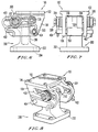
- Figure 7 corresponds to Figure 3 but shows the second embodiment;
- Figure 8 is a perspective view, from the posterior quarter and from above, of the second embodiment;
- Figure 9 is a side elevation of a fully extended knee mechanism of a third embodiment, viewed from the lateral side, with the anterior region to the right of the drawing and the posterior to the left;
- Figure 10 corresponds to Figure 3 but shows the third embodiment; and
- Figure 11 is a perspective view, from the posterior quarter and from above, of the third embodiment.
-
- The knee joint of the first embodiment illustrated in Figures 1-5 comprises an
upper member 1, alower member 2, and a polycentriclinkage including sliders 3,tracks 4 andcrank 5. The term "sliders" as used herein is broad enough to include rollers and other members capable of guided or confined movement with respect to thetracks 4. - Crank 5 rotates on
pins 6 and 7 which are retained inupper member 1 andlower member 2, respectively. Crank 5 has a generally U shape and comprisesside members 8 connected bybridge member 9 which provides resistance to torsional loads. The crank extends substantially vertically, and the pivotal connection of thecrank 5 with the upper member is below and anterior to the pivotal connection of the crank with said lower member, when thelower member 2 is in a fully extended position. - Sliders 3 roll in
tracks 4 and rotate onpin 10 which is retained inlower member 2. -
Tracks 4 are attached toupper member 1 bydowels 11 andscrews 12 and may be assembled in alternative positions to provide different levels of stability. They generally extend substantially perpendicular to the load line of the upper member. - Sleeve 13 fits over
pin 6 and abuts with a suitably shaped cutout inlower member 2 to provide an extension stop, although a stop may be provided by any pair of surfaces betweenupper member 1,lower member 2 orcrank 5. - The chain line 14 of Figure 2 represents the locus of the path of the instantaneous center of rotation at different positions of the mechanism and the arrowhead shows the direction of movement of the instantaneous center with increasing flexion.
-
Projections - Referring now to the second embodiment of Figures 6-8, the same reference numbers will be used to designate the same or corresponding parts as those of the first embodiment except that the respective reference numbers will include two additional zeros. The following description will focus on the differences between the embodiments.
- The
upper member 100 is in the form of arectangular plate 102 havingholes 104 for screws or bolts to be used for attachment to a thigh member of the prosthesis. A pair of dependingskirts 106 extend downward from theplate 102 and each includes a track in the form aslot 400. - The
lower member 200 has arectangular base 202 withbolt holes 204. Apedestal 206 extends upwardly from thebase 202 and includes a pair ofbosses 208, each having ahole 210 forming a journal bearing. Theholes 210 are aligned and are positioned between, and are aligned with, theslots 400 when the knee mechanism is in the illustrated fully extended position. - The
slider 300 comprises apin 302 rotatably mounted in the journal bearings of thebosses 208 and extending through theslots 400. The walls of theslots 400 guide and support thepin 302 during flexure of the knee mechanism. A pair ofrollers 304 are mounted on opposite ends of thepin 302. Thrust bearings in the form ofwashers 306 are mounted on thepin 302 between therollers 304 and theskirts 106. Therollers 304 are held on thepin 302 bynuts 308 threaded onto the ends of the pin. -
Anti-rattle spring wires 402 are mounted to the exterior sides of theskirts 106 at positions below and parallel to theslots 400. Thewires 402 resiliently press on concave peripheral surfaces of therollers 304 as theslider 300 moves along theslot 400 during flexion of the knee to prevent rattling of theslider 300 in theslot 400. - The
wires 402 are mounted at ends of apin 404 which pivotally supports one end of thecrank 500 in theupper member 100. Thecrank 500 is generally in the shape of an inverted T pivoted at itslower end 502 by thepin 404. Theupper end 504 of thecrank 500 fits between thebosses 208 and is pivotally connected to thelower member 200 by apin 506 extending through thebosses 208 and theupper end 504. - The operation of the second embodiment is substantially the same as that of the first embodiment.
- Referring now to the third embodiment of Figures 9-11, the same reference numbers will be used to designate the same or corresponding parts as those of the first embodiment except that the respective reference numbers will include three additional zeros. The following description will focus on the differences between the embodiments.
- The third embodiment is essentially the same as the second embodiment except that it uses a single central track and slider. The track takes the form of a tube or
rod 4002, preferably of circular section, rigidly fixed to the underside of theplate 1020 ofupper member 1000. Theplate 1020 hasscrew holes 1040. The slider takes the form of apivoting guide block 3002 pivoted to thelugs 2022 ofpedestals 2060 of thelower member 2000 at 3004 and has acentral bore 3006 housing a bushing 3008. The bushing may be the model L28 bushing sold by Igus Corp. Of Providence R.I. Thebushing 3008 is slidably fitted on therod 4002 and is guided along the rod as the knee mechanism is articulated. - The
crank 5000 is U shaped and is pivoted to the skirts 1006 of theupper member 1000 bypin 3020. It is also pivoted to thelug 2024 of the lower member. The lower member has arectangular plate 2020. - Obviously, numerous modifications and variations of the present invention are possible in light of the above teachings. It is therefore to be understood that within the scope of the appended claims, the invention may be practiced otherwise than as specifically described herein.
Claims (13)
- A knee mechanism for a lower limb prosthesis, comprising:characterised in that said polycentric linkage comprises a slider crank mechanism including:an upper member (1) connectable to a thigh so as to define a posterior and anterior orientation relative to a load line of the upper member (1),a lower member (2), anda polycentric linkage connecting said lower member (2) to said upper member (1);a track (4) mounted to said upper member (1),a slider (3) pivotally mounted to said lower member (2) and constrained by said track (4) to move in a direction substantially perpendicular to the load line of the upper member (1) anda crank (5) pivotally connected to said upper member (1) and to said lower member (2).
- A knee mechanism according to claim 1 wherein said polycentric linkage connects said lower member (2) to said upper member (1) such that said lower member (2) can rotate posteriorly from a fully extended position with respect to said upper member (1) about an instantaneous centre of rotation, wherein said instantaneous centre of rotation is above the knee mechanism and posterior to the load line when said lower member (2) is in the fully extended position.
- A knee mechanism according to claim 2, wherein the pivotal connnection of said slider (3) with said lower member (2) is posterior to the pivotal connection of said crank (5) with said lower member (2).
- A knee mechanism according to any of the preceding claims, wherein said crank (5) extends substantially vertically, and wherein the pivotal connection of said crank (5) with said upper member (1) is below and anterior to the pivotal connection of said crank (5) with said lower member (2) when said lower member (2) is in a fully extended position.
- A knee mechanism according to any of the preceding claims wherein said crank (5) is shaped to resist torsional loads applied thereto.
- A knee mechanism according to any of the preceding claims, wherein said crank (5) is U shaped.
- A knee mechanism according to any of claims 1 to 5, wherein said crank (5) is T shaped.
- A knee mechanism according to any of the preceding claims including an anti-rattle spring (402) engaging said slider (300).
- A knee mechanism according to any of the preceding claims, wherein a portion of said knee mechanism forms a stop preventing rotation of said lower member (2) beyond the fully extended position.
- A knee mechanism according to any of the preceding claims, wherein said track (4) is adjustably mounted to said upper member (1).
- A knee mechanism according to any of the preceding claims, wherein a portion (13) of said knee mechanism forms a stop preventing rotation of said lower member (2) beyond a selected flexion position.
- A knee mechanism according to any of the preceding claims wherein said track (4) comprises a rod (4002) fixed to said upper member (1) and said slider (3) comprises a guide element (3002) pivoted to said lower member (2) and slidably mounted on said rod (4002).
- A lower limb prosthesis comprising a knee mechanism according to any one of the preceding claims.
Applications Claiming Priority (3)
| Application Number | Priority Date | Filing Date | Title |
|---|---|---|---|
| GB9605110 | 1996-03-11 | ||
| GBGB9605110.7A GB9605110D0 (en) | 1996-03-11 | 1996-03-11 | Knee mechanism for an artificial limb |
| PCT/US1997/003658 WO1997033539A1 (en) | 1996-03-11 | 1997-03-10 | Knee mechanism for an artificial limb |
Publications (3)
| Publication Number | Publication Date |
|---|---|
| EP0955962A1 EP0955962A1 (en) | 1999-11-17 |
| EP0955962A4 EP0955962A4 (en) | 2000-08-23 |
| EP0955962B1 true EP0955962B1 (en) | 2004-09-22 |
Family
ID=10790192
Family Applications (1)
| Application Number | Title | Priority Date | Filing Date |
|---|---|---|---|
| EP97908970A Expired - Lifetime EP0955962B1 (en) | 1996-03-11 | 1997-03-10 | Knee mechanism for an artificial limb |
Country Status (7)
| Country | Link |
|---|---|
| US (1) | US5800567A (en) |
| EP (1) | EP0955962B1 (en) |
| AT (1) | ATE276718T1 (en) |
| AU (1) | AU2073997A (en) |
| DE (1) | DE69730865T2 (en) |
| GB (1) | GB9605110D0 (en) |
| WO (1) | WO1997033539A1 (en) |
Families Citing this family (19)
| Publication number | Priority date | Publication date | Assignee | Title |
|---|---|---|---|---|
| US6686717B2 (en) * | 1997-04-01 | 2004-02-03 | Charles Khairallah | Modular articulated structure |
| US6198247B1 (en) * | 1999-04-20 | 2001-03-06 | Steven Barr | Servo-articulated modules and robotic assemblies incorporating them |
| US6187052B1 (en) * | 1999-07-14 | 2001-02-13 | Joseph L. Molino | Prosthetic ankle joint |
| DE19935203C1 (en) * | 1999-07-27 | 2001-01-25 | Bock Orthopaed Ind | Hip joint for an artificial leg |
| US6764521B2 (en) | 2001-08-24 | 2004-07-20 | Joseph L. Molino | Multi-axial ankle joint |
| US7087090B2 (en) * | 2003-11-19 | 2006-08-08 | Bloorview Macmillan Centre | Artificial knee joint |
| US20050154473A1 (en) * | 2004-01-13 | 2005-07-14 | David Bassett | Prosthetic knee mechanism |
| WO2007008803A2 (en) * | 2005-07-11 | 2007-01-18 | Ossur Hf | Energy returing prosthetic joint |
| DE102006021064B4 (en) * | 2006-05-03 | 2010-09-02 | Otto Bock Healthcare Gmbh | Method for determining the installation height of a prosthesis |
| WO2010075112A1 (en) * | 2008-12-15 | 2010-07-01 | össur hf | Noise reduction device for articulating joint, and a limb support device having the same |
| EP2514372A1 (en) | 2011-04-21 | 2012-10-24 | Deru GmbH | Set of instruments for inserting a joint prosthetic, in particular knee prosthetic |
| USD732167S1 (en) | 2013-02-01 | 2015-06-16 | Limbs International Inc. | Prosthetic knee |
| USD732168S1 (en) | 2013-08-19 | 2015-06-16 | Limbs International Inc. | Prosthetic knee |
| AU2015360683B2 (en) * | 2014-12-08 | 2019-11-21 | Rehabilitation Institute Of Chicago | Powered and passive assistive device and related methods |
| USD785177S1 (en) | 2015-06-19 | 2017-04-25 | Limbs International Inc. | Prosthetic knee |
| KR102151159B1 (en) * | 2020-05-18 | 2020-09-03 | 주식회사 지아이지인터내셔널 | Automatic pumping device of the ventilator |
| KR102176247B1 (en) * | 2020-08-27 | 2020-11-10 | 주식회사 지아이지인터내셔널 | Ventilator capable of supplying the appropriate amount of air according to the patient |
| KR102176244B1 (en) * | 2020-08-27 | 2020-11-10 | 주식회사 지아이지인터내셔널 | Air supply device for ventilator |
| CN112043472A (en) * | 2020-10-16 | 2020-12-08 | 北京市康复辅具技术中心 | Single-shaft hydraulic knee joint |
Family Cites Families (17)
| Publication number | Priority date | Publication date | Assignee | Title |
|---|---|---|---|---|
| US2208275A (en) * | 1937-06-25 | 1940-07-16 | French J Conner | Artificial knee |
| US2667644A (en) * | 1948-07-03 | 1954-02-02 | Northrop Aircraft Inc | Anatomical knee and hydraulic snubber |
| US2599297A (en) * | 1949-08-31 | 1952-06-03 | Touson Isaac | Artificial limb |
| US3823424A (en) * | 1972-02-25 | 1974-07-16 | Hanger J And Co Ltd | Artificial leg with stable link-type knee joint |
| FR2344271A1 (en) * | 1976-03-17 | 1977-10-14 | Adcro Section Ceraval | Knee joint for artificial limb - has two links joining upper and lower parts together and third link on slide to adjust pivoting axis |
| US4064569A (en) * | 1976-09-23 | 1977-12-27 | Campbell Harry E | Artificial polycentric knee joint |
| GB1533796A (en) * | 1977-10-20 | 1978-11-29 | Blatchford & Sons Ltd C | Artificial leg |
| DE2841999C2 (en) * | 1978-09-27 | 1981-11-26 | Otto Bock, Orthopädische Industrie KG, 3428 Duderstadt | Artificial knee joint |
| FR2502937A1 (en) * | 1981-04-06 | 1982-10-08 | Perolini Charles | Poly-centric prosthetic knee joint - has shaft extending from tibial bearing surface fitted into tube implanted in tibia with limited rotation |
| US4723539A (en) * | 1984-08-13 | 1988-02-09 | Townsend Industries, Inc. | Multiaxis controlled motion knee orthosis |
| US4756712A (en) * | 1986-08-04 | 1988-07-12 | Orthomedics, Inc. | Knee joint assembly |
| DE3830330A1 (en) * | 1988-09-07 | 1990-03-15 | Schuett & Grundei Orthopaedie | KNEE JOINT FOR A LEG PROSTHESIS |
| GB9105464D0 (en) * | 1991-03-14 | 1991-05-01 | Blatchford & Sons Ltd | An artificial leg |
| GB9323425D0 (en) * | 1993-11-12 | 1994-01-05 | Cooper John E | Knee joint for an artificial limb |
| NL9400269A (en) * | 1994-02-22 | 1995-10-02 | P G Van De Veen Consultancy B | Device for pivotally connecting parts of an orthopedic device. |
| GB2307415B (en) * | 1994-09-09 | 1998-08-12 | Univ Toledo | Improved knee joint mechanism for knee disarticulation prosthesis |
| US5632725A (en) * | 1995-01-03 | 1997-05-27 | S.R. Orthopedic Laboratories, Inc. | Polycentric variable axis hinge for an orthopedic knee brace |
-
1996
- 1996-03-11 GB GBGB9605110.7A patent/GB9605110D0/en active Pending
-
1997
- 1997-03-10 AT AT97908970T patent/ATE276718T1/en not_active IP Right Cessation
- 1997-03-10 US US08/816,002 patent/US5800567A/en not_active Expired - Lifetime
- 1997-03-10 EP EP97908970A patent/EP0955962B1/en not_active Expired - Lifetime
- 1997-03-10 DE DE69730865T patent/DE69730865T2/en not_active Expired - Lifetime
- 1997-03-10 AU AU20739/97A patent/AU2073997A/en not_active Abandoned
- 1997-03-10 WO PCT/US1997/003658 patent/WO1997033539A1/en not_active Ceased
Also Published As
| Publication number | Publication date |
|---|---|
| EP0955962A4 (en) | 2000-08-23 |
| EP0955962A1 (en) | 1999-11-17 |
| ATE276718T1 (en) | 2004-10-15 |
| US5800567A (en) | 1998-09-01 |
| AU2073997A (en) | 1997-10-01 |
| DE69730865D1 (en) | 2004-10-28 |
| GB9605110D0 (en) | 1996-05-08 |
| WO1997033539A1 (en) | 1997-09-18 |
| DE69730865T2 (en) | 2005-09-22 |
Similar Documents
| Publication | Publication Date | Title |
|---|---|---|
| US5800567A (en) | Knee mechanism for an artificial limb | |
| US4005496A (en) | Prosthetic knee joint | |
| US5549689A (en) | Prosthetic knee | |
| US4911709A (en) | Artificial knee with improved stable link-type knee joint | |
| US4605417A (en) | Prosthetic joint | |
| JP3698726B2 (en) | Prosthetic knee joint device | |
| US3946446A (en) | Prosthetic bone joint | |
| JP3701066B2 (en) | Prosthetic joint with applicable movable joint between two bones | |
| US4865606A (en) | Endoprosthesis for a knee-joint | |
| EP1121074B1 (en) | Jellybean knee joint (improvement) | |
| US5171325A (en) | Hinge structure for prosthetic joint | |
| US4112522A (en) | Knee-joint prosthesis | |
| US20040220676A1 (en) | Coupled knee prosthesis with a rotational bearing | |
| EP0366436A2 (en) | Adjustable hinge device | |
| US5419754A (en) | Knee brace | |
| CA2079587A1 (en) | Artificial Toggle Joint | |
| EP0587721B1 (en) | Artificial foot | |
| US6746414B1 (en) | Joint for a knee brace incorporating a locking mechanism | |
| DE69900323D1 (en) | Connecting mechanism | |
| GB2134392A (en) | Improvements in four bar linkages for knee joints of artificial legs | |
| DE3561614D1 (en) | Knee joint endoprosthesis | |
| EP0095872A1 (en) | Improvements in or relating to knee joints for artificial legs | |
| GB2283920A (en) | Polycentric knee mechanism | |
| CA2217844C (en) | Prosthetic knee joint with enhanced posterior stabilization | |
| EP0325347A1 (en) | Knee prosthesis |
Legal Events
| Date | Code | Title | Description |
|---|---|---|---|
| PUAI | Public reference made under article 153(3) epc to a published international application that has entered the european phase |
Free format text: ORIGINAL CODE: 0009012 |
|
| 17P | Request for examination filed |
Effective date: 19981009 |
|
| AK | Designated contracting states |
Kind code of ref document: A1 Designated state(s): AT BE CH DE DK ES FI FR GB GR IE IT LI LU MC NL PT SE |
|
| A4 | Supplementary search report drawn up and despatched |
Effective date: 20000707 |
|
| AK | Designated contracting states |
Kind code of ref document: A4 Designated state(s): AT BE CH DE DK ES FI FR GB GR IE IT LI LU MC NL PT SE |
|
| RIC1 | Information provided on ipc code assigned before grant |
Free format text: 7A 61F 2/62 A, 7A 61F 2/64 B |
|
| 17Q | First examination report despatched |
Effective date: 20030314 |
|
| GRAP | Despatch of communication of intention to grant a patent |
Free format text: ORIGINAL CODE: EPIDOSNIGR1 |
|
| GRAS | Grant fee paid |
Free format text: ORIGINAL CODE: EPIDOSNIGR3 |
|
| GRAA | (expected) grant |
Free format text: ORIGINAL CODE: 0009210 |
|
| AK | Designated contracting states |
Kind code of ref document: B1 Designated state(s): AT BE CH DE DK ES FI FR GB GR IE IT LI LU MC NL PT SE |
|
| PG25 | Lapsed in a contracting state [announced via postgrant information from national office to epo] |
Ref country code: NL Free format text: LAPSE BECAUSE OF FAILURE TO SUBMIT A TRANSLATION OF THE DESCRIPTION OR TO PAY THE FEE WITHIN THE PRESCRIBED TIME-LIMIT Effective date: 20040922 Ref country code: LI Free format text: LAPSE BECAUSE OF FAILURE TO SUBMIT A TRANSLATION OF THE DESCRIPTION OR TO PAY THE FEE WITHIN THE PRESCRIBED TIME-LIMIT Effective date: 20040922 Ref country code: IT Free format text: LAPSE BECAUSE OF FAILURE TO SUBMIT A TRANSLATION OF THE DESCRIPTION OR TO PAY THE FEE WITHIN THE PRE;WARNING: LAPSES OF ITALIAN PATENTS WITH EFFECTIVE DATE BEFORE 2007 MAY HAVE OCCURRED AT ANY TIME BEFORE 2007. THE CORRECT EFFECTIVE DATE MAY BE DIFFERENT FROM THE ONE RECORDED.SCRIBED TIME-LIMIT Effective date: 20040922 Ref country code: FR Free format text: LAPSE BECAUSE OF FAILURE TO SUBMIT A TRANSLATION OF THE DESCRIPTION OR TO PAY THE FEE WITHIN THE PRESCRIBED TIME-LIMIT Effective date: 20040922 Ref country code: FI Free format text: LAPSE BECAUSE OF FAILURE TO SUBMIT A TRANSLATION OF THE DESCRIPTION OR TO PAY THE FEE WITHIN THE PRESCRIBED TIME-LIMIT Effective date: 20040922 Ref country code: CH Free format text: LAPSE BECAUSE OF FAILURE TO SUBMIT A TRANSLATION OF THE DESCRIPTION OR TO PAY THE FEE WITHIN THE PRESCRIBED TIME-LIMIT Effective date: 20040922 Ref country code: BE Free format text: LAPSE BECAUSE OF FAILURE TO SUBMIT A TRANSLATION OF THE DESCRIPTION OR TO PAY THE FEE WITHIN THE PRESCRIBED TIME-LIMIT Effective date: 20040922 Ref country code: AT Free format text: LAPSE BECAUSE OF FAILURE TO SUBMIT A TRANSLATION OF THE DESCRIPTION OR TO PAY THE FEE WITHIN THE PRESCRIBED TIME-LIMIT Effective date: 20040922 |
|
| REG | Reference to a national code |
Ref country code: GB Ref legal event code: FG4D |
|
| REG | Reference to a national code |
Ref country code: CH Ref legal event code: EP |
|
| REG | Reference to a national code |
Ref country code: IE Ref legal event code: FG4D |
|
| REF | Corresponds to: |
Ref document number: 69730865 Country of ref document: DE Date of ref document: 20041028 Kind code of ref document: P |
|
| PG25 | Lapsed in a contracting state [announced via postgrant information from national office to epo] |
Ref country code: GR Free format text: LAPSE BECAUSE OF FAILURE TO SUBMIT A TRANSLATION OF THE DESCRIPTION OR TO PAY THE FEE WITHIN THE PRESCRIBED TIME-LIMIT Effective date: 20041222 Ref country code: DK Free format text: LAPSE BECAUSE OF FAILURE TO SUBMIT A TRANSLATION OF THE DESCRIPTION OR TO PAY THE FEE WITHIN THE PRESCRIBED TIME-LIMIT Effective date: 20041222 |
|
| PG25 | Lapsed in a contracting state [announced via postgrant information from national office to epo] |
Ref country code: ES Free format text: LAPSE BECAUSE OF FAILURE TO SUBMIT A TRANSLATION OF THE DESCRIPTION OR TO PAY THE FEE WITHIN THE PRESCRIBED TIME-LIMIT Effective date: 20050102 |
|
| REG | Reference to a national code |
Ref country code: SE Ref legal event code: TRGR |
|
| PG25 | Lapsed in a contracting state [announced via postgrant information from national office to epo] |
Ref country code: LU Free format text: LAPSE BECAUSE OF NON-PAYMENT OF DUE FEES Effective date: 20050310 Ref country code: IE Free format text: LAPSE BECAUSE OF NON-PAYMENT OF DUE FEES Effective date: 20050310 |
|
| PG25 | Lapsed in a contracting state [announced via postgrant information from national office to epo] |
Ref country code: MC Free format text: LAPSE BECAUSE OF NON-PAYMENT OF DUE FEES Effective date: 20050331 |
|
| REG | Reference to a national code |
Ref country code: CH Ref legal event code: PL |
|
| NLV1 | Nl: lapsed or annulled due to failure to fulfill the requirements of art. 29p and 29m of the patents act | ||
| PLBE | No opposition filed within time limit |
Free format text: ORIGINAL CODE: 0009261 |
|
| STAA | Information on the status of an ep patent application or granted ep patent |
Free format text: STATUS: NO OPPOSITION FILED WITHIN TIME LIMIT |
|
| 26N | No opposition filed |
Effective date: 20050623 |
|
| EN | Fr: translation not filed | ||
| REG | Reference to a national code |
Ref country code: IE Ref legal event code: MM4A |
|
| PG25 | Lapsed in a contracting state [announced via postgrant information from national office to epo] |
Ref country code: PT Free format text: LAPSE BECAUSE OF NON-PAYMENT OF DUE FEES Effective date: 20050222 |
|
| PGFP | Annual fee paid to national office [announced via postgrant information from national office to epo] |
Ref country code: SE Payment date: 20090317 Year of fee payment: 13 |
|
| EUG | Se: european patent has lapsed | ||
| PG25 | Lapsed in a contracting state [announced via postgrant information from national office to epo] |
Ref country code: SE Free format text: LAPSE BECAUSE OF NON-PAYMENT OF DUE FEES Effective date: 20100311 |
|
| PGFP | Annual fee paid to national office [announced via postgrant information from national office to epo] |
Ref country code: DE Payment date: 20130327 Year of fee payment: 17 |
|
| PGFP | Annual fee paid to national office [announced via postgrant information from national office to epo] |
Ref country code: GB Payment date: 20140618 Year of fee payment: 18 |
|
| REG | Reference to a national code |
Ref country code: DE Ref legal event code: R119 Ref document number: 69730865 Country of ref document: DE |
|
| REG | Reference to a national code |
Ref country code: DE Ref legal event code: R119 Ref document number: 69730865 Country of ref document: DE Effective date: 20141001 |
|
| PG25 | Lapsed in a contracting state [announced via postgrant information from national office to epo] |
Ref country code: DE Free format text: LAPSE BECAUSE OF NON-PAYMENT OF DUE FEES Effective date: 20141001 |
|
| GBPC | Gb: european patent ceased through non-payment of renewal fee |
Effective date: 20150310 |
|
| PG25 | Lapsed in a contracting state [announced via postgrant information from national office to epo] |
Ref country code: GB Free format text: LAPSE BECAUSE OF NON-PAYMENT OF DUE FEES Effective date: 20150310 |