EP0955078A1 - Filter for fluids having differentiated filtration regions - Google Patents
Filter for fluids having differentiated filtration regions Download PDFInfo
- Publication number
- EP0955078A1 EP0955078A1 EP99107405A EP99107405A EP0955078A1 EP 0955078 A1 EP0955078 A1 EP 0955078A1 EP 99107405 A EP99107405 A EP 99107405A EP 99107405 A EP99107405 A EP 99107405A EP 0955078 A1 EP0955078 A1 EP 0955078A1
- Authority
- EP
- European Patent Office
- Prior art keywords
- layer
- filter according
- filter
- paper
- filtration
- Prior art date
- Legal status (The legal status is an assumption and is not a legal conclusion. Google has not performed a legal analysis and makes no representation as to the accuracy of the status listed.)
- Ceased
Links
- 238000001914 filtration Methods 0.000 title claims abstract description 61
- 239000012530 fluid Substances 0.000 title claims abstract description 23
- 239000003365 glass fiber Substances 0.000 claims description 10
- 239000012209 synthetic fiber Substances 0.000 claims description 7
- 229920002994 synthetic fiber Polymers 0.000 claims description 7
- 239000000758 substrate Substances 0.000 claims description 3
- 230000015572 biosynthetic process Effects 0.000 claims description 2
- 238000000034 method Methods 0.000 claims description 2
- 239000004745 nonwoven fabric Substances 0.000 claims description 2
- 239000000123 paper Substances 0.000 claims description 2
- 230000008569 process Effects 0.000 claims description 2
- 230000000284 resting effect Effects 0.000 claims 1
- 238000009825 accumulation Methods 0.000 description 6
- 230000035699 permeability Effects 0.000 description 6
- 239000012535 impurity Substances 0.000 description 5
- 239000000463 material Substances 0.000 description 5
- 239000002283 diesel fuel Substances 0.000 description 3
- 239000010687 lubricating oil Substances 0.000 description 3
- 239000003921 oil Substances 0.000 description 3
- 239000002245 particle Substances 0.000 description 3
- 238000002485 combustion reaction Methods 0.000 description 2
- 230000003750 conditioning effect Effects 0.000 description 2
- 239000000446 fuel Substances 0.000 description 2
- 239000000126 substance Substances 0.000 description 2
- 238000004026 adhesive bonding Methods 0.000 description 1
- 239000003570 air Substances 0.000 description 1
- 238000004378 air conditioning Methods 0.000 description 1
- 229920002678 cellulose Polymers 0.000 description 1
- 239000001913 cellulose Substances 0.000 description 1
- 230000008878 coupling Effects 0.000 description 1
- 238000010168 coupling process Methods 0.000 description 1
- 238000005859 coupling reaction Methods 0.000 description 1
- 230000007423 decrease Effects 0.000 description 1
- 230000001419 dependent effect Effects 0.000 description 1
- 230000000694 effects Effects 0.000 description 1
- 238000005516 engineering process Methods 0.000 description 1
- 239000000835 fiber Substances 0.000 description 1
- 230000000670 limiting effect Effects 0.000 description 1
- 238000012986 modification Methods 0.000 description 1
- 230000004048 modification Effects 0.000 description 1
- 238000003672 processing method Methods 0.000 description 1
- 230000000717 retained effect Effects 0.000 description 1
- 238000005096 rolling process Methods 0.000 description 1
Images





Classifications
-
- B—PERFORMING OPERATIONS; TRANSPORTING
- B01—PHYSICAL OR CHEMICAL PROCESSES OR APPARATUS IN GENERAL
- B01D—SEPARATION
- B01D46/00—Filters or filtering processes specially modified for separating dispersed particles from gases or vapours
- B01D46/52—Particle separators, e.g. dust precipitators, using filters embodying folded corrugated or wound sheet material
- B01D46/521—Particle separators, e.g. dust precipitators, using filters embodying folded corrugated or wound sheet material using folded, pleated material
-
- B—PERFORMING OPERATIONS; TRANSPORTING
- B01—PHYSICAL OR CHEMICAL PROCESSES OR APPARATUS IN GENERAL
- B01D—SEPARATION
- B01D27/00—Cartridge filters of the throw-away type
- B01D27/04—Cartridge filters of the throw-away type with cartridges made of a piece of unitary material, e.g. filter paper
- B01D27/06—Cartridge filters of the throw-away type with cartridges made of a piece of unitary material, e.g. filter paper with corrugated, folded or wound material
-
- B—PERFORMING OPERATIONS; TRANSPORTING
- B01—PHYSICAL OR CHEMICAL PROCESSES OR APPARATUS IN GENERAL
- B01D—SEPARATION
- B01D27/00—Cartridge filters of the throw-away type
- B01D27/08—Construction of the casing
-
- B—PERFORMING OPERATIONS; TRANSPORTING
- B01—PHYSICAL OR CHEMICAL PROCESSES OR APPARATUS IN GENERAL
- B01D—SEPARATION
- B01D27/00—Cartridge filters of the throw-away type
- B01D27/14—Cartridge filters of the throw-away type having more than one filtering element
- B01D27/146—Cartridge filters of the throw-away type having more than one filtering element connected in series
- B01D27/148—Cartridge filters of the throw-away type having more than one filtering element connected in series arranged concentrically or coaxially
-
- B—PERFORMING OPERATIONS; TRANSPORTING
- B01—PHYSICAL OR CHEMICAL PROCESSES OR APPARATUS IN GENERAL
- B01D—SEPARATION
- B01D29/00—Filters with filtering elements stationary during filtration, e.g. pressure or suction filters, not covered by groups B01D24/00 - B01D27/00; Filtering elements therefor
- B01D29/01—Filters with filtering elements stationary during filtration, e.g. pressure or suction filters, not covered by groups B01D24/00 - B01D27/00; Filtering elements therefor with flat filtering elements
- B01D29/05—Filters with filtering elements stationary during filtration, e.g. pressure or suction filters, not covered by groups B01D24/00 - B01D27/00; Filtering elements therefor with flat filtering elements supported
- B01D29/07—Filters with filtering elements stationary during filtration, e.g. pressure or suction filters, not covered by groups B01D24/00 - B01D27/00; Filtering elements therefor with flat filtering elements supported with corrugated, folded or wound filtering sheets
-
- B—PERFORMING OPERATIONS; TRANSPORTING
- B01—PHYSICAL OR CHEMICAL PROCESSES OR APPARATUS IN GENERAL
- B01D—SEPARATION
- B01D29/00—Filters with filtering elements stationary during filtration, e.g. pressure or suction filters, not covered by groups B01D24/00 - B01D27/00; Filtering elements therefor
- B01D29/11—Filters with filtering elements stationary during filtration, e.g. pressure or suction filters, not covered by groups B01D24/00 - B01D27/00; Filtering elements therefor with bag, cage, hose, tube, sleeve or like filtering elements
- B01D29/13—Supported filter elements
- B01D29/15—Supported filter elements arranged for inward flow filtration
- B01D29/21—Supported filter elements arranged for inward flow filtration with corrugated, folded or wound sheets
-
- B—PERFORMING OPERATIONS; TRANSPORTING
- B01—PHYSICAL OR CHEMICAL PROCESSES OR APPARATUS IN GENERAL
- B01D—SEPARATION
- B01D29/00—Filters with filtering elements stationary during filtration, e.g. pressure or suction filters, not covered by groups B01D24/00 - B01D27/00; Filtering elements therefor
- B01D29/50—Filters with filtering elements stationary during filtration, e.g. pressure or suction filters, not covered by groups B01D24/00 - B01D27/00; Filtering elements therefor with multiple filtering elements, characterised by their mutual disposition
- B01D29/56—Filters with filtering elements stationary during filtration, e.g. pressure or suction filters, not covered by groups B01D24/00 - B01D27/00; Filtering elements therefor with multiple filtering elements, characterised by their mutual disposition in series connection
- B01D29/58—Filters with filtering elements stationary during filtration, e.g. pressure or suction filters, not covered by groups B01D24/00 - B01D27/00; Filtering elements therefor with multiple filtering elements, characterised by their mutual disposition in series connection arranged concentrically or coaxially
-
- B—PERFORMING OPERATIONS; TRANSPORTING
- B01—PHYSICAL OR CHEMICAL PROCESSES OR APPARATUS IN GENERAL
- B01D—SEPARATION
- B01D39/00—Filtering material for liquid or gaseous fluids
- B01D39/10—Filter screens essentially made of metal
- B01D39/12—Filter screens essentially made of metal of wire gauze; of knitted wire; of expanded metal
-
- B—PERFORMING OPERATIONS; TRANSPORTING
- B01—PHYSICAL OR CHEMICAL PROCESSES OR APPARATUS IN GENERAL
- B01D—SEPARATION
- B01D39/00—Filtering material for liquid or gaseous fluids
- B01D39/14—Other self-supporting filtering material ; Other filtering material
- B01D39/16—Other self-supporting filtering material ; Other filtering material of organic material, e.g. synthetic fibres
- B01D39/1607—Other self-supporting filtering material ; Other filtering material of organic material, e.g. synthetic fibres the material being fibrous
- B01D39/1623—Other self-supporting filtering material ; Other filtering material of organic material, e.g. synthetic fibres the material being fibrous of synthetic origin
-
- B—PERFORMING OPERATIONS; TRANSPORTING
- B01—PHYSICAL OR CHEMICAL PROCESSES OR APPARATUS IN GENERAL
- B01D—SEPARATION
- B01D39/00—Filtering material for liquid or gaseous fluids
- B01D39/14—Other self-supporting filtering material ; Other filtering material
- B01D39/16—Other self-supporting filtering material ; Other filtering material of organic material, e.g. synthetic fibres
- B01D39/18—Other self-supporting filtering material ; Other filtering material of organic material, e.g. synthetic fibres the material being cellulose or derivatives thereof
-
- B—PERFORMING OPERATIONS; TRANSPORTING
- B01—PHYSICAL OR CHEMICAL PROCESSES OR APPARATUS IN GENERAL
- B01D—SEPARATION
- B01D39/00—Filtering material for liquid or gaseous fluids
- B01D39/14—Other self-supporting filtering material ; Other filtering material
- B01D39/20—Other self-supporting filtering material ; Other filtering material of inorganic material, e.g. asbestos paper, metallic filtering material of non-woven wires
- B01D39/2003—Glass or glassy material
- B01D39/2017—Glass or glassy material the material being filamentary or fibrous
-
- B—PERFORMING OPERATIONS; TRANSPORTING
- B01—PHYSICAL OR CHEMICAL PROCESSES OR APPARATUS IN GENERAL
- B01D—SEPARATION
- B01D46/00—Filters or filtering processes specially modified for separating dispersed particles from gases or vapours
- B01D46/10—Particle separators, e.g. dust precipitators, using filter plates, sheets or pads having plane surfaces
-
- B—PERFORMING OPERATIONS; TRANSPORTING
- B01—PHYSICAL OR CHEMICAL PROCESSES OR APPARATUS IN GENERAL
- B01D—SEPARATION
- B01D46/00—Filters or filtering processes specially modified for separating dispersed particles from gases or vapours
- B01D46/24—Particle separators, e.g. dust precipitators, using rigid hollow filter bodies
- B01D46/2403—Particle separators, e.g. dust precipitators, using rigid hollow filter bodies characterised by the physical shape or structure of the filtering element
- B01D46/2411—Filter cartridges
-
- B—PERFORMING OPERATIONS; TRANSPORTING
- B01—PHYSICAL OR CHEMICAL PROCESSES OR APPARATUS IN GENERAL
- B01D—SEPARATION
- B01D2201/00—Details relating to filtering apparatus
- B01D2201/18—Filters characterised by the openings or pores
- B01D2201/188—Multiple filtering elements having filtering areas of different size
-
- B—PERFORMING OPERATIONS; TRANSPORTING
- B01—PHYSICAL OR CHEMICAL PROCESSES OR APPARATUS IN GENERAL
- B01D—SEPARATION
- B01D2275/00—Filter media structures for filters specially adapted for separating dispersed particles from gases or vapours
- B01D2275/10—Multiple layers
-
- B—PERFORMING OPERATIONS; TRANSPORTING
- B01—PHYSICAL OR CHEMICAL PROCESSES OR APPARATUS IN GENERAL
- B01D—SEPARATION
- B01D2275/00—Filter media structures for filters specially adapted for separating dispersed particles from gases or vapours
- B01D2275/30—Porosity of filtering material
- B01D2275/305—Porosity decreasing in flow direction
-
- B—PERFORMING OPERATIONS; TRANSPORTING
- B01—PHYSICAL OR CHEMICAL PROCESSES OR APPARATUS IN GENERAL
- B01D—SEPARATION
- B01D2279/00—Filters adapted for separating dispersed particles from gases or vapours specially modified for specific uses
- B01D2279/50—Filters adapted for separating dispersed particles from gases or vapours specially modified for specific uses for air conditioning
Definitions
- the present invention relates to a filter for fluids.
- filters are also found in the circuits that carry Diesel fuel from the tank to internal-combustion engines or boilers and in the gasoline circuits of said engines, and there is also a wide range of air filters for civil, industrial and vehicle air-conditioning systems.
- Conventional filters have various constructive shapes, but substantially they all consist of a structure for supporting and containing a filtering mass through which the fluid to be filtered is made to pass by flowing between a region connected to an inlet connector and a region connected to an outlet connector.
- a widely used filtering medium is constituted by a sheet which comprises a plurality of layers and is inserted in the filter after being folded or rolled up so as to give a large area to the filtering surface despite the compact size of the filter.
- the sheet comprises a layer which, on its own, performs the proper filtering function, retaining all the impurities contained in the fluid to be filtered, regardless of their size so long as they are above a technically compatible minimum size, and such layer is accompanied by at least one layer which acts purely as a support; the layer that performs the filtering function is usually made of glass fiber, while the one or more supporting layers are made of paper, always arranged at the outlet of the fluid, or of synthetic fibers.
- the glass fiber, the paper and the synthetic fibers can optionally receive the addition of other substances in a manner known per se.
- the paper it should also be noted that it is always cellulose-derived paper.
- the aim of the present invention is to provide a filter for fluids having a filtering mass which can optimize operating conditions both in terms of accumulation capacity and filtration efficiency.
- a filter for fluids which comprises a container defining a chamber which is connected to an inlet connector and to an outlet connector, said chamber containing a filtering mass which is crossed by the circulation of a fluid to be filtered, characterized in that said filtering mass comprises at least one layer which is meant to be the first one crossed by said fluid, is suitable to produce a coarse filtration and is made of paper, and a second layer which is adapted to provide a fine filtration.
- the filter is also characterized in that the filtering mass comprises a third supporting layer which is arranged so as to be last layer crossed by the fluid.
- the reference numeral 1 designates the first paper layer meant to be crossed by the fluid to be filtered, as shown by the arrows.
- Such layer is suitable to produce a coarse filtration, i.e., to retain particles larger than, for example, 25 microns.
- the reference numeral 2 designates a layer made of glass fibers, which is suitable to provide a fine filtration, i.e., to retain particles of impurities larger than, for example, 7 microns.
- the reference numeral 3 designates a supporting layer which is arranged so as to be the last layer crossed by the fluid.
- Such layer is made of a paper which obviously has a higher permeability than, or at the most the same permeability as, the paper of the first layer 1.
- the three layers, before being folded or rolled up to form the filtering mass to be inserted in a filter, can be joined by simple contact or can be rigidly coupled for example by gluing, stitching, thermal bonding or pressure points: said layers might also be produced together during a single formation process.
- the described filtering mass has a high functionality, because the particles of impurities are retained so as to be distributed over two layers according to their size; this fact gives the filter a high accumulation capacity and optimum efficiency, which is also the result of the possibility to vary the characteristics of the individual layers.
- the material of the layer 3 directed toward the outlet of the fluid was kept constant, adopting paper with a higher permeability than the other two layers, and the material, i.e. glass fiber, that constituted the intermediate layer 2 on which filtration efficiency is substantially dependent was also kept constant, and different types of paper, with different permeabilities for an equal average grammage, were adopted for the layer 1, and it was found that the accumulation capacity of the filter increases as the permeability of layer 1 decreases, while filtration efficiency remains substantially constant owing to the unchanging characteristics of the material of layer 2.
- a plurality of filters comprising a filtering mass produced by using the sheet of Figure 1 is now described; such filters are chosen merely by way of example.
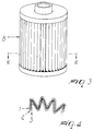
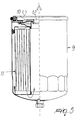
- the reference numeral 4 designates a lubricating oil filter which comprises a per se known structure which is suitable to produce, inside a container 5, the oil circulation shown by the arrows between the inlet connector 6 and the outlet connector 7, passing through the filtering mass 8, which is formed by folding, as shown in Figure 4, the sheet of Figure 1.
- Fuel filters also have the same structure.
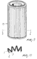
- Figures 5, 6 and 7 relate to a filter 9, which is meant to filter Diesel fuel which is introduced through a connector 10, flows along the circuit shown by the arrows, passing through a filtering mass 11 obtained by rolling the sheet of Figure 1, and leaves through a connector 12.
- Figures 8, 9 and 10 illustrate characteristics of an air filter 13 for a heavy-duty application in which the air enters through a connector 14 and flows through a circuit which makes it pass through a filtering mass 15 obtained by folding, as shown in Figure 10, the sheet of Figure 1, and then leaves through a connector 16.
- Filtering mass 17 of an air filter 18 for a conditioning system is also formed by folding the sheet of Figure 1.
- layer 2 can be made of synthetic fibers or paper, instead of glass fiber, having a higher degree of filtration than layer 1, and that the supporting layer 3 can also be made of non-woven fabric or mesh instead of paper.
- Figure 13 illustrates a different embodiment in which the sheet of filtering mass comprises only the layers 1 and 2 which are meant to be crossed successively by the fluid to be filtered, entering through the layer 1 to provide, respectively, a coarse filtration and a fine filtration, which are produced exactly as described for the corresponding layers of the embodiment shown in Figure 1 and without a supporting layer.
- Figure 14 illustrates a further embodiment in which, without altering the description given for layer 1, layer 2 is formed by means of two substrates 2a and 2b, each of which can be made of glass fiber, synthetic fibers, or paper with a higher degree of filtration than layer 1; it is thus possible to have two substrates with identical or different fiber characteristics according to requirements.
Landscapes
- Chemical & Material Sciences (AREA)
- Chemical Kinetics & Catalysis (AREA)
- Physics & Mathematics (AREA)
- Geometry (AREA)
- Engineering & Computer Science (AREA)
- Textile Engineering (AREA)
- Life Sciences & Earth Sciences (AREA)
- Geology (AREA)
- Filtering Materials (AREA)
- Lubrication Details And Ventilation Of Internal Combustion Engines (AREA)
- Water Treatment By Sorption (AREA)
Abstract
Description
- The present invention relates to a filter for fluids.
- It is known that many fields of technology use filters meant to retain impurities contained in the most disparate fluids.
- This is the case, for example, of the circuits for lubricating oil of internal-combustion engines, which is pumped continuously, during operation, from a sump which acts as a reservoir and is sent to lubricate the kinematic couplings provided in the motors after passing through a filter which retains the impurities.
- However, filters are also found in the circuits that carry Diesel fuel from the tank to internal-combustion engines or boilers and in the gasoline circuits of said engines, and there is also a wide range of air filters for civil, industrial and vehicle air-conditioning systems.
- Conventional filters have various constructive shapes, but substantially they all consist of a structure for supporting and containing a filtering mass through which the fluid to be filtered is made to pass by flowing between a region connected to an inlet connector and a region connected to an outlet connector.
- The filtering mass too takes on the most disparate shapes, both in terms of the material used and in terms of the processing method; a widely used filtering medium is constituted by a sheet which comprises a plurality of layers and is inserted in the filter after being folded or rolled up so as to give a large area to the filtering surface despite the compact size of the filter.
- More specifically, the sheet comprises a layer which, on its own, performs the proper filtering function, retaining all the impurities contained in the fluid to be filtered, regardless of their size so long as they are above a technically compatible minimum size, and such layer is accompanied by at least one layer which acts purely as a support; the layer that performs the filtering function is usually made of glass fiber, while the one or more supporting layers are made of paper, always arranged at the outlet of the fluid, or of synthetic fibers.
- The glass fiber, the paper and the synthetic fibers can optionally receive the addition of other substances in a manner known per se.
- Hereinafter, when using the terms "glass fiber", "paper" or "synthetic fibers", it is understood that such terms refer to said materials with the optional addition of other substances.
- As regards the paper, it should also be noted that it is always cellulose-derived paper.
- The drawback of the described type of filtering mass is the fact that any increase in filtration efficiency has a negative effect on accumulation capacity.
- Accordingly, the aim of the present invention is to provide a filter for fluids having a filtering mass which can optimize operating conditions both in terms of accumulation capacity and filtration efficiency.
- This aim is achieved by a filter for fluids, according to the invention, which comprises a container defining a chamber which is connected to an inlet connector and to an outlet connector, said chamber containing a filtering mass which is crossed by the circulation of a fluid to be filtered, characterized in that said filtering mass comprises at least one layer which is meant to be the first one crossed by said fluid, is suitable to produce a coarse filtration and is made of paper, and a second layer which is adapted to provide a fine filtration.
- Advantageously, the filter is also characterized in that the filtering mass comprises a third supporting layer which is arranged so as to be last layer crossed by the fluid.
- Further characteristics and advantages of the present invention will become apparent from the following detailed description of some preferred but not exclusive embodiments thereof, illustrated only by way of non-limitative example in the accompanying drawings, wherein:
- Figure 1 is a perspective view of a portion of a sheet of filtering mass according to a first embodiment of the present invention;
- Figure 2 is a partially sectional side view of a filter for lubricating oil which is provided with a filtering mass formed by a sheet of the type shown in Figure 1;
- Figure 3 is a perspective view of the filtering mass of the filter of Figure 2;
- Figure 4 is an enlarged-scale partial sectional view, taken along the plane IV-IV of Figure 3;
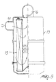
- Figure 5 is a partially sectional side view of a filter for Diesel fuel provided with a filtering mass formed by a sheet of the type shown in Figure 1;
- Figure 6 is a perspective view of the filtering mass of the filter of Figure 5;
- Figure 7 is an enlarged-scale partial sectional view, taken along the plane VII-VII of Figure 6;
- Figure 8 is a partially sectional side view of an air filter provided with a filtering mass formed by a sheet of the type shown in Figure 1;
- Figure 9 is a perspective view of the filtering mass of the filter of Figure 8;
- Figure 10 is an enlarged-scale partial sectional view, taken along the plane X-X of Figure 9;
- Figure 11 is a perspective view of the filtering mass of an air filter for a conditioning system;
- Figure 12 is an enlarged-scale partial sectional view, taken along the plane XII-XII of Figure 11;
- Figures 13, 14 and 15 are views of a portion of a sheet of filtering mass according to different embodiments of the invention.
- With reference to Figure 1, the
reference numeral 1 designates the first paper layer meant to be crossed by the fluid to be filtered, as shown by the arrows. Such layer is suitable to produce a coarse filtration, i.e., to retain particles larger than, for example, 25 microns. - The
reference numeral 2 designates a layer made of glass fibers, which is suitable to provide a fine filtration, i.e., to retain particles of impurities larger than, for example, 7 microns. - Finally, the
reference numeral 3 designates a supporting layer which is arranged so as to be the last layer crossed by the fluid. Such layer is made of a paper which obviously has a higher permeability than, or at the most the same permeability as, the paper of thefirst layer 1. - The three layers, before being folded or rolled up to form the filtering mass to be inserted in a filter, can be joined by simple contact or can be rigidly coupled for example by gluing, stitching, thermal bonding or pressure points: said layers might also be produced together during a single formation process.
- The described filtering mass has a high functionality, because the particles of impurities are retained so as to be distributed over two layers according to their size; this fact gives the filter a high accumulation capacity and optimum efficiency, which is also the result of the possibility to vary the characteristics of the individual layers.
- All this is confirmed by tests conducted on oil filters executed according to the structure shown in Figures 2, 3 and 4 with a filtering mass according to Figure 1.
- The material of the
layer 3 directed toward the outlet of the fluid was kept constant, adopting paper with a higher permeability than the other two layers, and the material, i.e. glass fiber, that constituted theintermediate layer 2 on which filtration efficiency is substantially dependent was also kept constant, and different types of paper, with different permeabilities for an equal average grammage, were adopted for thelayer 1, and it was found that the accumulation capacity of the filter increases as the permeability oflayer 1 decreases, while filtration efficiency remains substantially constant owing to the unchanging characteristics of the material oflayer 2. - Moreover, it has been found that if the permeability of the paper that constitutes
layer 1 is kept the same, by varying the degree of filtration of the glass fiber that constituteslayer 2 an increase in the accumulation capacity is achieved as said degree of filtration increases. - It has thus been found experimentally that it is possible to achieve high filtration efficiency and at the same time a high accumulation capacity substantially thanks to the contribution of the layer of
paper 1 arranged at the inlet of the fluid, which can be constituted equally by oil, fuel or air. - A plurality of filters comprising a filtering mass produced by using the sheet of Figure 1 is now described; such filters are chosen merely by way of example.
- With reference to Figures 2, 3 and 4, the
reference numeral 4 designates a lubricating oil filter which comprises a per se known structure which is suitable to produce, inside acontainer 5, the oil circulation shown by the arrows between the inlet connector 6 and theoutlet connector 7, passing through the filteringmass 8, which is formed by folding, as shown in Figure 4, the sheet of Figure 1. - Fuel filters also have the same structure.
- Figures 5, 6 and 7 relate to a
filter 9, which is meant to filter Diesel fuel which is introduced through aconnector 10, flows along the circuit shown by the arrows, passing through a filteringmass 11 obtained by rolling the sheet of Figure 1, and leaves through aconnector 12. - Figures 8, 9 and 10 illustrate characteristics of an
air filter 13 for a heavy-duty application in which the air enters through aconnector 14 and flows through a circuit which makes it pass through a filteringmass 15 obtained by folding, as shown in Figure 10, the sheet of Figure 1, and then leaves through aconnector 16. - Filtering
mass 17 of anair filter 18 for a conditioning system, to which Figures 11 and 12 relate, is also formed by folding the sheet of Figure 1. - To conclude the description of the embodiment of the sheet of filtering mass shown in Figure 1, it is noted that
layer 2 can be made of synthetic fibers or paper, instead of glass fiber, having a higher degree of filtration thanlayer 1, and that the supportinglayer 3 can also be made of non-woven fabric or mesh instead of paper. - Figure 13 illustrates a different embodiment in which the sheet of filtering mass comprises only the
layers layer 1 to provide, respectively, a coarse filtration and a fine filtration, which are produced exactly as described for the corresponding layers of the embodiment shown in Figure 1 and without a supporting layer. - Figure 14 illustrates a further embodiment in which, without altering the description given for
layer 1,layer 2 is formed by means of two substrates 2a and 2b, each of which can be made of glass fiber, synthetic fibers, or paper with a higher degree of filtration thanlayer 1; it is thus possible to have two substrates with identical or different fiber characteristics according to requirements. - In the embodiment of Figure 14 there is no supporting layer; such layer is instead present, and designated by the
reference numeral 3, in the embodiment shown in Figure 15, which is otherwise identical. - The described invention is susceptible of numerous other modifications and variations, all of which are within the scope of the inventive concept; all the details may further be replaced with other technically equivalent elements.
- The disclosures in Italian Patent Application No. MI98A000987 from which this application claims priority are incorporated herein by reference.
- Where technical features mentioned in any claim are followed by reference signs, those reference signs have been included for the sole purpose of increasing the intelligibility of the claims and accordingly, such reference signs do not have any limiting effect on the interpretation of each element identified by way of example by such reference signs.
Claims (12)
- A filter for fluids, comprising a container defining a chamber which is connected to an inlet connector and to an outlet connector, said chamber containing a filtering mass which is crossed by the circulation of a fluid to be filtered, characterized in that said filtering mass comprises at least one layer which is meant to be the first one crossed by said fluid, is suitable to produce a coarse filtration and is made of paper, and a second layer which is suitable to provide a fine filtration.
- The filter according to claim 1, characterized in that the second layer suitable to produce a fine filtration is made monolithically of glass fiber.
- The filter according to claim 1, characterized in that the second layer suitable to produce a fine filtration is made monolithically of synthetic fibers.
- The filter according to claim 1, characterized in that the second layer suitable to produce a fine filtration is made monolithically of paper with a higher degree of filtration than the first layer.
- The filter according to claim 1, characterized in that the second layer suitable to produce a fine filtration is made of two substrates, each of which is made of glass fiber, synthetic fibers, or paper with a higher degree of filtration than the first layer.
- The filter according to claim 1, characterized in that the at least two layers are mutually joined by simply resting on each other.
- The filter according to claim 1, characterized in that the at least two layers are coupled.
- The filter according to claim 1, characterized in that the at least two layers are rigidly coupled by being produced together during a single formation process.
- The filter according to claim 1, characterized in that the filtering mass comprises a third supporting layer which is arranged so that it is the last layer crossed by the fluid.
- The filter according to claim 9, characterized in that the third supporting layer is made of paper.
- The filter according to claim 9, characterized in that the third supporting layer is made of non-woven fabric.
- The filter according to claim 9, characterized in that the third supporting layer is made of mesh.
Applications Claiming Priority (2)
| Application Number | Priority Date | Filing Date | Title |
|---|---|---|---|
| IT1998MI000987A IT1303067B1 (en) | 1998-05-06 | 1998-05-06 | FILTER FOR FLUIDS WITH DIFFERENTIATED FILTRATION AREAS |
| ITMI980987 | 1998-05-06 |
Publications (1)
| Publication Number | Publication Date |
|---|---|
| EP0955078A1 true EP0955078A1 (en) | 1999-11-10 |
Family
ID=11379969
Family Applications (1)
| Application Number | Title | Priority Date | Filing Date |
|---|---|---|---|
| EP99107405A Ceased EP0955078A1 (en) | 1998-05-06 | 1999-04-26 | Filter for fluids having differentiated filtration regions |
Country Status (2)
| Country | Link |
|---|---|
| EP (1) | EP0955078A1 (en) |
| IT (1) | IT1303067B1 (en) |
Cited By (10)
| Publication number | Priority date | Publication date | Assignee | Title |
|---|---|---|---|---|
| WO2002060559A3 (en) * | 2001-01-31 | 2002-10-24 | Sogefi S P A | Filtering mass in filter for fluids with layered arrangement |
| EP1249261A3 (en) * | 2001-04-10 | 2002-11-27 | Parker Hannifin Corporation | Pleated filter element and method of making said element |
| EP1245263A3 (en) * | 2001-03-29 | 2003-07-23 | Kyosan Denki Co., Ltd. | Fluid filtering member |
| RU2287358C1 (en) * | 2005-06-08 | 2006-11-20 | Николай Яковлевич ЗАЙЦЕВ | Separating filter element for cleaning and drying gases |
| WO2010102061A1 (en) * | 2009-03-06 | 2010-09-10 | Dionex Corporation | Fluid sample delivery system and method |
| JP2013504409A (en) * | 2009-09-12 | 2013-02-07 | ハイダック フィルターテヒニク ゲゼルシャフト ミット ベシュレンクテル ハフツング | Method for forming a filter element having a filter medium |
| DE102015002323A1 (en) | 2014-02-25 | 2015-08-27 | Mann + Hummel Gmbh | Multi-layer filter medium and related manufacturing process |
| WO2015157638A3 (en) * | 2014-04-10 | 2015-12-10 | Donaldson Company, Inc. | Pleated fluid filter element and methods |
| CN108295584A (en) * | 2018-04-17 | 2018-07-20 | 东莞市东田过滤技术有限公司 | A kind of filter core and its filter for exempting from metal material |
| CN110087752A (en) * | 2016-12-21 | 2019-08-02 | 约翰斯曼维尔欧洲有限公司 | High-efficiency filtration media |
Citations (4)
| Publication number | Priority date | Publication date | Assignee | Title |
|---|---|---|---|---|
| EP0060677A1 (en) * | 1981-03-13 | 1982-09-22 | AMSTED Industries Incorporated | Composite filter media |
| US5275743A (en) * | 1991-12-10 | 1994-01-04 | Pall Corporation | Filter and filtration method |
| US5403482A (en) * | 1993-10-12 | 1995-04-04 | Gelman Sciences Inc. | Self-supporting, pleated, spirally wound filter and the corresponding process of making |
| EP0793990A2 (en) * | 1996-03-06 | 1997-09-10 | UFI Universal Filter International S.p.A. | Process for manufacturing a filter medium, the medium manufactured thereby, and filters using said medium |
-
1998
- 1998-05-06 IT IT1998MI000987A patent/IT1303067B1/en active IP Right Grant
-
1999
- 1999-04-26 EP EP99107405A patent/EP0955078A1/en not_active Ceased
Patent Citations (4)
| Publication number | Priority date | Publication date | Assignee | Title |
|---|---|---|---|---|
| EP0060677A1 (en) * | 1981-03-13 | 1982-09-22 | AMSTED Industries Incorporated | Composite filter media |
| US5275743A (en) * | 1991-12-10 | 1994-01-04 | Pall Corporation | Filter and filtration method |
| US5403482A (en) * | 1993-10-12 | 1995-04-04 | Gelman Sciences Inc. | Self-supporting, pleated, spirally wound filter and the corresponding process of making |
| EP0793990A2 (en) * | 1996-03-06 | 1997-09-10 | UFI Universal Filter International S.p.A. | Process for manufacturing a filter medium, the medium manufactured thereby, and filters using said medium |
Cited By (23)
| Publication number | Priority date | Publication date | Assignee | Title |
|---|---|---|---|---|
| WO2002060559A3 (en) * | 2001-01-31 | 2002-10-24 | Sogefi S P A | Filtering mass in filter for fluids with layered arrangement |
| EP1245263A3 (en) * | 2001-03-29 | 2003-07-23 | Kyosan Denki Co., Ltd. | Fluid filtering member |
| EP1249261A3 (en) * | 2001-04-10 | 2002-11-27 | Parker Hannifin Corporation | Pleated filter element and method of making said element |
| US7438812B2 (en) | 2001-04-10 | 2008-10-21 | Parker-Hannifin Corporation | Filter element and method of making |
| RU2287358C1 (en) * | 2005-06-08 | 2006-11-20 | Николай Яковлевич ЗАЙЦЕВ | Separating filter element for cleaning and drying gases |
| CN102421495B (en) * | 2009-03-06 | 2015-11-25 | 迪奥尼克斯公司 | Fluid sample delivery system and method |
| WO2010102061A1 (en) * | 2009-03-06 | 2010-09-10 | Dionex Corporation | Fluid sample delivery system and method |
| CN102421495A (en) * | 2009-03-06 | 2012-04-18 | 迪奥尼克斯公司 | Fluid sample delivery system and method |
| JP2012519855A (en) * | 2009-03-06 | 2012-08-30 | ダイオネックス コーポレイション | Fluid sample delivery system and method |
| US8776621B2 (en) | 2009-03-06 | 2014-07-15 | Dionex Corporation | Fluid sample delivery system and method |
| JP2013504409A (en) * | 2009-09-12 | 2013-02-07 | ハイダック フィルターテヒニク ゲゼルシャフト ミット ベシュレンクテル ハフツング | Method for forming a filter element having a filter medium |
| DE102015002323A1 (en) | 2014-02-25 | 2015-08-27 | Mann + Hummel Gmbh | Multi-layer filter medium and related manufacturing process |
| WO2015157638A3 (en) * | 2014-04-10 | 2015-12-10 | Donaldson Company, Inc. | Pleated fluid filter element and methods |
| CN106457081A (en) * | 2014-04-10 | 2017-02-22 | 唐纳森公司 | Pleated fluid filter element and method |
| US10653979B2 (en) | 2014-04-10 | 2020-05-19 | Donaldson Company, Inc. | Pleated fluid filter element and methods |
| US11376526B2 (en) | 2014-04-10 | 2022-07-05 | Donaldson Company, Inc. | Pleated fluid filter element and methods |
| CN115591300A (en) * | 2014-04-10 | 2023-01-13 | 唐纳森公司(Us) | Pleated fluid filter element and method |
| EP4129440A1 (en) * | 2014-04-10 | 2023-02-08 | Donaldson Company, Inc. | Pleated fluid filter element |
| US11883765B2 (en) | 2014-04-10 | 2024-01-30 | Donaldson Company, Inc. | Pleated fluid filter element and methods |
| US12318713B2 (en) | 2014-04-10 | 2025-06-03 | Donaldson Company, Inc. | Pleated fluid filter element and methods |
| CN110087752A (en) * | 2016-12-21 | 2019-08-02 | 约翰斯曼维尔欧洲有限公司 | High-efficiency filtration media |
| CN110087752B (en) * | 2016-12-21 | 2021-09-07 | 约翰斯曼维尔欧洲有限公司 | High-efficiency filter media |
| CN108295584A (en) * | 2018-04-17 | 2018-07-20 | 东莞市东田过滤技术有限公司 | A kind of filter core and its filter for exempting from metal material |
Also Published As
| Publication number | Publication date |
|---|---|
| IT1303067B1 (en) | 2000-10-23 |
| ITMI980987A1 (en) | 1999-11-06 |
Similar Documents
| Publication | Publication Date | Title |
|---|---|---|
| US4976858A (en) | Multi-layer filter medium | |
| US7137510B1 (en) | Filter element | |
| US20020056684A1 (en) | Multilayer filter element | |
| EP0558091B1 (en) | Filtration apparatus | |
| US6569330B1 (en) | Filter coalescer cartridge | |
| JP6265544B2 (en) | Filter media | |
| US12370469B2 (en) | Perforated layer coalescer | |
| US8021455B2 (en) | Filter element and method | |
| EP2143934B1 (en) | Filter apparatus for fuel | |
| EP1399238B1 (en) | Hybrid spin-on filter | |
| CN106687190A (en) | Filter media including oriented fibers | |
| US20110168622A1 (en) | High Efficiency, High Capacity Filter Media | |
| JPH0214708A (en) | Triple filter type disposable oil filter unit | |
| EP0793990A2 (en) | Process for manufacturing a filter medium, the medium manufactured thereby, and filters using said medium | |
| US5382361A (en) | Liquid and entrained air filter | |
| CN108778460B (en) | Filter element of fuel filter and fuel filter | |
| ITMI980987A1 (en) | FILTER FOR FLUIDS WITH DIFFERENTIATED FILTRATION AREAS | |
| EP1357991B1 (en) | Filter for fluids with layered arrangement | |
| JPH0824535A (en) | Filter medium and filtration method | |
| JP3492429B2 (en) | Filter element | |
| WO1997033673A1 (en) | Filter for fluids having an improved filtering mass | |
| KR100294896B1 (en) | filter | |
| JP3459326B2 (en) | Full flow type oil filter element for internal combustion engine | |
| JPH07116424A (en) | Fluid filter material |
Legal Events
| Date | Code | Title | Description |
|---|---|---|---|
| PUAI | Public reference made under article 153(3) epc to a published international application that has entered the european phase |
Free format text: ORIGINAL CODE: 0009012 |
|
| AK | Designated contracting states |
Kind code of ref document: A1 Designated state(s): AT BE CH CY DE DK ES FI FR GB GR IE IT LI LU MC NL PT SE |
|
| AX | Request for extension of the european patent |
Free format text: AL;LT;LV;MK;RO;SI |
|
| 17P | Request for examination filed |
Effective date: 20000425 |
|
| AKX | Designation fees paid |
Free format text: AT BE CH CY DE DK ES FI FR GB GR IE IT LI LU MC NL PT SE |
|
| AXX | Extension fees paid |
Free format text: AL PAYMENT 20000425;LT PAYMENT 20000425;LV PAYMENT 20000425;MK PAYMENT 20000425;RO PAYMENT 20000425;SI PAYMENT 20000425 |
|
| 17Q | First examination report despatched |
Effective date: 20051207 |
|
| STAA | Information on the status of an ep patent application or granted ep patent |
Free format text: STATUS: THE APPLICATION HAS BEEN REFUSED |
|
| 18R | Application refused |
Effective date: 20091123 |