EP0954766B1 - Apparatus and method for minimizing the drying of a coating fluid on a slide coater surface - Google Patents
Apparatus and method for minimizing the drying of a coating fluid on a slide coater surface Download PDFInfo
- Publication number
- EP0954766B1 EP0954766B1 EP97946475A EP97946475A EP0954766B1 EP 0954766 B1 EP0954766 B1 EP 0954766B1 EP 97946475 A EP97946475 A EP 97946475A EP 97946475 A EP97946475 A EP 97946475A EP 0954766 B1 EP0954766 B1 EP 0954766B1
- Authority
- EP
- European Patent Office
- Prior art keywords
- fluid
- coating
- slide
- slide surface
- coating fluid
- Prior art date
- Legal status (The legal status is an assumption and is not a legal conclusion. Google has not performed a legal analysis and makes no representation as to the accuracy of the status listed.)
- Expired - Lifetime
Links
Images

Classifications
-
- B—PERFORMING OPERATIONS; TRANSPORTING
- B05—SPRAYING OR ATOMISING IN GENERAL; APPLYING FLUENT MATERIALS TO SURFACES, IN GENERAL
- B05D—PROCESSES FOR APPLYING FLUENT MATERIALS TO SURFACES, IN GENERAL
- B05D1/00—Processes for applying liquids or other fluent materials
- B05D1/26—Processes for applying liquids or other fluent materials performed by applying the liquid or other fluent material from an outlet device in contact with, or almost in contact with, the surface
-
- B—PERFORMING OPERATIONS; TRANSPORTING
- B05—SPRAYING OR ATOMISING IN GENERAL; APPLYING FLUENT MATERIALS TO SURFACES, IN GENERAL
- B05C—APPARATUS FOR APPLYING FLUENT MATERIALS TO SURFACES, IN GENERAL
- B05C5/00—Apparatus in which liquid or other fluent material is projected, poured or allowed to flow on to the surface of the work
- B05C5/007—Slide-hopper coaters, i.e. apparatus in which the liquid or other fluent material flows freely on an inclined surface before contacting the work
-
- G—PHYSICS
- G03—PHOTOGRAPHY; CINEMATOGRAPHY; ANALOGOUS TECHNIQUES USING WAVES OTHER THAN OPTICAL WAVES; ELECTROGRAPHY; HOLOGRAPHY
- G03C—PHOTOSENSITIVE MATERIALS FOR PHOTOGRAPHIC PURPOSES; PHOTOGRAPHIC PROCESSES, e.g. CINE, X-RAY, COLOUR, STEREO-PHOTOGRAPHIC PROCESSES; AUXILIARY PROCESSES IN PHOTOGRAPHY
- G03C1/00—Photosensitive materials
- G03C1/74—Applying photosensitive compositions to the base; Drying processes therefor
-
- B—PERFORMING OPERATIONS; TRANSPORTING
- B05—SPRAYING OR ATOMISING IN GENERAL; APPLYING FLUENT MATERIALS TO SURFACES, IN GENERAL
- B05C—APPARATUS FOR APPLYING FLUENT MATERIALS TO SURFACES, IN GENERAL
- B05C9/00—Apparatus or plant for applying liquid or other fluent material to surfaces by means not covered by any preceding group, or in which the means of applying the liquid or other fluent material is not important
- B05C9/06—Apparatus or plant for applying liquid or other fluent material to surfaces by means not covered by any preceding group, or in which the means of applying the liquid or other fluent material is not important for applying two different liquids or other fluent materials, or the same liquid or other fluent material twice, to the same side of the work
-
- Y—GENERAL TAGGING OF NEW TECHNOLOGICAL DEVELOPMENTS; GENERAL TAGGING OF CROSS-SECTIONAL TECHNOLOGIES SPANNING OVER SEVERAL SECTIONS OF THE IPC; TECHNICAL SUBJECTS COVERED BY FORMER USPC CROSS-REFERENCE ART COLLECTIONS [XRACs] AND DIGESTS
- Y10—TECHNICAL SUBJECTS COVERED BY FORMER USPC
- Y10S—TECHNICAL SUBJECTS COVERED BY FORMER USPC CROSS-REFERENCE ART COLLECTIONS [XRACs] AND DIGESTS
- Y10S118/00—Coating apparatus
- Y10S118/04—Curtain coater
Definitions
- the present invention relates to a method for minimizing the drying of a coating fluid on a slide coater surface, wherein the coating is intended to create, for example, a photothermographic, thermographic, or photographic element, data storage element (e.g., a magnetic computer tape and floppy or rigid disks or diskettes, and the like), or other material which is susceptible to such drying.
- a photothermographic, thermographic, or photographic element e.g., a magnetic computer tape and floppy or rigid disks or diskettes, and the like
- data storage element e.g., a magnetic computer tape and floppy or rigid disks or diskettes, and the like
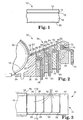
- FIG. 1 A construction of a known photothermographic dry silver film or paper product 10 is shown in Figure 1.
- This construction can be created by coating a plurality of layers onto a substrate.
- One of the layers is a photothermographic emulsion layer 14 made up of a photosensitized silver soap in a binder resin which can include toners, developers, sensitizers and stabilizers.
- a primer layer 16 can be positioned between them.
- a topcoat layer 12 can be positioned above the photothermographic emulsion layer 14 and can be made up of a mar-resistant hard resin with toners and slip agents.
- the substrate 18 can be a paper-based substrate or a polymeric film-based substrate.
- An antihalation layer 20 can be applied to the surface of the substrate 18 opposite the surface on which the primer, photothermographic emulsion, and topcoat layers 16, 14, 12 can be positioned.
- the compositions of layers 16, 14 and 12 are chosen for product performance reasons, and components comprising adjacent coating layers could be incompatible.
- phase separation can result in the inability to coat such a construction using a multi-layer coating technique due to formation of defects such as streaks or fish-eyes, or due to a disruption of flow and the intermixing of separate fluid layers.
- U.S. Patent No. 4,113,903 (Choinski, 1978) teaches that a low viscosity carrier layer tends to be unstable "in the bridge between the coater lip and the web in the bead formed with a bead coater" and can limit the web speed at which the method can be applied.
- Choinski suggests use of a non-Newtonian pseudoplastic liquid as the carrier, such that it has a high viscosity on the slide and in the bead where the shear rate is low, and a low viscosity near the dynamic contact line where the shear rate is high.
- U.S. Patent No. 4,863,765 (Ishizuka, 1988) teaches that using a thin layer of distilled water as carrier allows high coating speeds and also eliminates mixing between the two lowermost layers.
- U.S. Patent No. 4,976,999 and U.S. Patent No. 4,977,852 (Ishizuka, 1990a and 1990b)
- the carrier slide construction with water as carrier (as described in U.S. Patent No. 4,863,765) is used, and it is noted that streaking is reduced by using smaller slot heights for the carrier layer and that bead edges are stabilized by extending the width of the carrier layer beyond the width of the other layers coated above the carrier.
- This patent also does not address strikethrough or phase separation.
- U.S. Patent Nos. 4,001,024, 4,113,903, and 4,525,392 require that the composition of the two bottom layers be adjusted such that interlayer mixing between these layers in the coating bead not lead to defects in the product.
- U.S. Patent No. 4,572,849 (and related U.S. Patent No. 4,569,863), while not restricting layer composition, restricts the coating gap to the range 100 ⁇ m - 400 ⁇ m.
- U.S. Patent Nos. 4,863,765, 4,976,999 and 4,977,852 while not specifically requiring a composition adjustment, are restricted to aqueous solutions by use of distilled water as carrier.
- coating fluids are collected by a vacuum box trough or drain trough and drained to a scrap receptacle. This has the disadvantage of wasting coating fluid(s).
- Yet another alternative is to reduce rather than completely stop the flow of coating fluid(s).
- this method is used with volatile organic solvent based coatings, undesirable dry-out and/or coagulation of the coating fluid(s) on the slide surface and in the slide slots still occurs due to the rapid evaporation of the volatile organic solvent. Again, when coating is resumed streak elimination must be repeated, and stable fluid flows must be reestablished.
- the invention described here is an apparatus and a method for use with a slide coater.
- the method can include the step of flowing a first coating fluid down at least a first slide surface of a slide coater when coating of the first coating fluid from the at least first slide surface onto a substrate is desired. Another step can involve flowing a minimizing fluid down the at least first slide surface.
- the minimizing fluid has a composition which minimizes drying of the first coating fluid on the at least first slide surface.
- the apparatus can include means for accomplishing the method steps noted above.
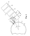
- Figures 2 and 3 illustrate a slide coating apparatus 30 generally made up of a coating back-up roller 32 for the substrate 18, and a slide coater 34.
- the slide coater 34 includes five slide blocks 36, 38, 40, 42, 44 which define four fluid slots 46, 48, 50, 52 and a slide surface 53.
- the first slide block is adjacent to the coating back-up roller 32 and includes a vacuum box 54 for adjusting the vacuum level by the slide coating apparatus 30.
- the vacuum box serves to maintain a differential pressure across the coating bead, thereby stabilizing it.
- a first fluid 55 can be distributed to the first slot 46 via a first fluid supply 56 and a first manifold 58.
- a second fluid 60 can be distributed to the second slot 48 via a second fluid supply 62 and a second manifold 64.
- a third fluid 66 can be distributed to the third fluid slot 50 via a third fluid supply 68 and a third fluid manifold 70.
- a fourth fluid 72 can be distributed to the fourth fluid slot 52 via a fourth fluid supply 74 and a fourth fluid manifold 76.
- This embodiment allows for the creation of up to a four-layer fluid construction 78 including a first fluid layer 80 (a.k.a., a carrier layer), a second fluid layer 82, a third fluid layer 84, and a fourth fluid layer 86. Additional slide blocks can be added for the introduction of additional fluid layers, as required for product performance or ease of operability.
- the fluid manifolds 58, 64, 70 and 76 are designed to allow uniform width-wise distribution out of fluid slots 46, 48, 50, 52, respectively.
- This design is specific to the choice of slot height H (illustrated in Figure 4) for the slots 46, 48, 50, 52.
- the slot height H is made sufficiently small such that the pressure drop in the slot is much higher than the pressure drop across the manifold (without causing undue problems of non-uniformity due to machining limitations or bar deflection due to excessive pressure in the die slot). This ensures that the fluid distributes uniformly in the slot. It is known that slot heights are made smaller when lower flow rates are desired.
- the design of the fluid manifold can also be made specific to the rheology of the fluid that it will carry, taking into account material properties such as but not limited to zero-shear viscosity, the power law index, fluid elasticity, and extensional behavior.
- the fluid supply can be located either at the end of the fluid manifold (end-fed design) or at the center of the fluid manifold (center-fed design).
- the principles of manifold design are also well-documented in literature (see, for example, Gutoff, "Simplified Design of Coating Die Internals," Journal of Imaging Science and Technology, 1993, 37(6) , 615-627) and could be used for all die-fed coating processes such as but not limited to slide, extrusion, and curtain coating. Further details of a preferred manifold design are noted later within this disclosure.
- the slide blocks 38, 40, 42, 44 can be configured to have specific slot heights H as depicted in Figure 4, chosen amongst other reasons to minimize pressure in the die manifolds and to overcome problems of non-uniformity due to machining limitations.
- the slot heights typically used range between 100 - 1500 ⁇ m.
- the slide blocks 38, 40, 42, 44 can also be arranged with a level offset so as to result in slot steps T, also depicted in Figure 4. These steps can aid the uniform flow of fluid down the slide surface 53 by minimizing the possibility of flow separation and fluid recirculation zones that can lead to streaking and other product defects.
- These slot steps can range from 100 - 2000 ⁇ m in height. The use of such steps is well-documented.
- Another method of minimizing the occurrence of flow separation on the slide surface 53 is by machining chamfers C on the downstream side of a fluid slot, as depicted in Figure 4, and could also be used in the embodiment of slide coating as described in this application.
- the finish of the block edges that form the edges of the fluid slots 46, 48, 50, and 52 are important, as is also the front edge of the front block 36 that is adjacent to backup roller 32.
- the presence of nicks, burrs or other defects on these edges can lead to streaking defects in the product.
- the edges are polished to a finish of less than 0.02 ⁇ m. Details regarding the procedure for finishing the die edges are disclosed in PCT publications WO96/39276 and WO 96/39275.
- Figure 4 also illustrates the orientation of the slide coater 34 relative to the back-up roller 32, including the position angle P, attack angle A, and the slide angle S.
- the slide angle S is the sum of the position angle P and the attack angle A.
- a negative position angle P is preferred so as to allow for increased wrap on the back-up roller and thereby greater stability for the coating operation.
- the method could also be used with a zero or positive position angle.
- the slide angle S determines the stability of the flow of fluids down the inclined slide plane. A large slide angle S can lead to the development of surface wave instabilities and consequently coating defects.
- the slide angle is typically set in the range from slightly greater than zero to 45°.
- the distance between the slide coater 34 and the roller 32 at the point of closest approach is known as the gap G.
- the wet thickness W of each layer is the thickness on the surface of the coated substrate 18 substantially far away from the coated bead, but close enough before appreciable drying has occurred.
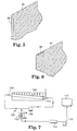
- Figures 5 and 6 illustrate portions of the slide coater which include durable, low surface energy portions 88. These portions 88 are intended to provide the desired surface energy properties to specific locations to uniformly pin the coating fluid to prevent build-up of dried material.
- Figure 7 illustrates a particular type of end-fed manifold 100 and a recirculation loop 102.
- the manifold 100 is shown as being inclined towards the outlet port 106 such that the depth of the slot L decreases from the inlet port 104 to the outlet port 106.
- the incline angle is carefully adjusted to take into account the pressure drop in the fluid as it traverses from the inlet port 104 of the manifold 100 to the outlet port 106 to ensure that the width-wise fluid distribution at the exit of the slot is uniform.
- the illustrated manifold design only a portion of the fluid that enters the manifold 100 leaves through the fluid slot (such as slots 46, 48, 50, or 52), while the remainder flows out through the outlet port 106 to the recirculation loop 102.
- the portion which flows through the outlet port 106 can be recirculated back to the inlet port 104 by a recirculation pump 108.
- the recirculation pump 108 can receive fresh fluid from a fluid reservoir 110 and fresh fluid pump 112.
- a fluid filter 114 and heat exchanger 116 can be included to filter and heat or cool the fresh fluid before it mixes with the recycled fluid.
- the manifold design i.e., the cavity shape and angle of incline, however, depends not only on the choice of slot height and fluid rheology, but on the percent recirculation used.
- the use of a similar recirculation loop for preventing agglomeration in the manifold during coating of highly shear-thinning magnetic materials is disclosed in U.S. Patent No. 4,623,501 (Ishizaki, 1986).
- edge guides 119 serve to pin the solution to the solid surface and result in a fixed width of coating and also stabilize the flow of fluid at the edges.
- the particular type of edge guide 119 illustrated in Figure 3 is commonly known in the coating art. Note that the edge guides are straight, and direct flow perpendicular to the slots 46, 48, 50, 52 over the slide surface.
- the edge guides 119 can be made of one material including metals such as steel, aluminum, etc.; polymers such as polytetrafluoroethylene (e.g., TEFLONTM), polyamide (e.g., NYLONTM), poly(methylene oxide) or polyacetal (e.g., DELRINTM), etc.; wood; ceramic, etc., or can be made of more than one material such as steel coated with polytetrafluoroethylene.
- polymers such as polytetrafluoroethylene (e.g., TEFLONTM), polyamide (e.g., NYLONTM), poly(methylene oxide) or polyacetal (e.g., DELRINTM), etc.
- wood ceramic, etc., or can be made of more than one material such as steel coated with polytetrafluoroethylene.
- the edge guides 119A can be of a convergent type, as illustrated in Figure 8.
- the angle of convergence ⁇ can be between 0° and 90°, with 0° corresponding to the case of straight edge guides of Figure 3.
- the angle ⁇ can be chosen for increased stability of the coating bead edges by increasing coating thickness at the bead edges relative to the center.
- the edge guides can include durable, low surface energy surfaces or portions as described previously.
- a cover or shroud over the slide coater 34 can be used (not shown).
- a sixth slide block (not shown) can be added to those shown in Figures 2 and 3 and can be positioned adjacent to the fifth slide block 44.
- the sixth slide block allows for the introduction of a fifth fluid (not shown) that can coat over the coating surfaces of the first, second, third, fourth, and fifth slide blocks 36, 38, 40, 42, 44.
- the fifth fluid can be used to address the previously described problems of material waste, drying, and streaking that are encountered when it becomes necessary to interrupt the coating process.
- the fifth fluid can form a protective blanket over the other coating fluid(s) which minimizes, if not eliminates, drying of these coating fluids on the slide surface and edge guides.
- the fifth fluid can also self-clean various slide surfaces of contaminants and debris and can pre-wet the slide surface(s) before the coating fluid(s) are introduced to the slide surface(s).
- a fluid can be thought of as a "minimizing fluid” as it minimizes or reduces defects related to, for example, drying and poor wetting of the coating fluid(s), or related to the presence of contaminants or debris on the slide surface(s).
- the fifth fluid can be directed down slide coater 34 when slide coater 34 is a sufficient distance from coating back-up roller 32 such that the fifth fluid does not contact back-up roller 32 or substrate 18, but flows down the front of the first slide block 36 and into the vacuum box and drain.
- the fifth fluid can be composed of a solvent compatible with the solvent system of the coating fluid(s) and can be dispensed at the start-up of a coating run before the flows of the coating fluid(s) are begun; during a short pause in coating above the flows of the coating fluid(s); and alone with the flows of the coating fluid(s) turned off during a prolonged pause in coating or after a coating run has been completed.
- the fifth fluid can be, for example, 100 percent solvent and can be chosen to be miscible with solvents used for the coating fluid(s). It may be filtered in-line or pre-filtered so that no contaminating materials (e.g., particles, fibers) are introduced onto the coating surfaces.
- the flow of fifth fluid is started first to completely pre-wet and clean the coating surface of slide coater 34.
- the flow of coating fluid(s) are then started in order (fluid layers 1, 2, 3, 4, ...) and the flow of each of the fluid layers is established.
- the fifth fluid flow is then stopped and the coater die moved toward back-up roller 32 for pick-up of coating onto the web.
- the fifth fluid assists in the rapid establishment of streak free coating flows.
- the coating assembly When coating is paused or stopped, the coating assembly is retracted from back-up roller 32, and the flow of the first, second, third, and fourth fluids 80, 82, 84, 86 is reduced or stopped to minimize the waste of coating fluid(s).
- the flow of the fifth fluid is started while the flow of coating fluid(s) is substantially reduced.
- the blanket of solvent lying over the coating fluid(s) on the slide surface minimizes or eliminates drying, coagulation, or particle formation within a coating fluid(s) that can cause streaks when coating is resumed.
- the fifth fluid flow is stopped, the flow of coating fluid(s) is increased to normal levels, and the coater die is moved toward back-up roller 32 for pick-up of coating onto the web.
- the fifth fluid assists in the rapid re-establishment of streak free coating flows.
- the flow of the fifth fluid is started while the flow of coating fluid(s) is completely stopped, leaving only the continuous flow of the fifth fluid. In this manner the entire slide surface is self-cleaned by the continuous solvent flow and the drying of any residual coating fluid(s) on various surfaces of the slide coater is minimized, if not entirely prevented.
- the coating fluid layers are restarted in order (fluid layers 1, 2, 3, 4, ...) while the fifth fluid flow is continued. After the coating flows are re-established, the fifth fluid flow is stopped and the coater die engaged to back-up roller 32 for pick-up of coating onto the web.
- the fifth fluid assists in the rapid re-establishment of streak free coating flows.
- the "minimizing" fluid (now a fourth fluid) could be dispensed from the fourth or fifth slot.
- the "minimizing" fluid could instead be a third fluid which minimizes the drying of a first and second fluid.
- the "minimizing” fluid could instead be a second fluid which minimizes the drying of a single coating fluid.
- the solvent flow system need not even be made with the same precision as the coating fluid system.
- the supply of the solvent layer to the surface of the slide coater can be by any suitable means.
- solvent can be delivered to the slide surface by using spray nozzles, porous wicks, porous metal inserts, etc.
Landscapes
- Chemical & Material Sciences (AREA)
- Engineering & Computer Science (AREA)
- Materials Engineering (AREA)
- Physics & Mathematics (AREA)
- General Physics & Mathematics (AREA)
- Coating Apparatus (AREA)
- Application Of Or Painting With Fluid Materials (AREA)
- Non-Silver Salt Photosensitive Materials And Non-Silver Salt Photography (AREA)
Description
Claims (15)
- A method for use with a slide coater (34), the method comprising the steps of:flowing a first coating fluid (55) at a first flow rate down at least a first slide surface (53) of a slide coater (34);coating a substrate (18)' supported on a back-up roller (32) with the first coating fluid (80);retracting the slide coater from the substrate and the back-up roller to interrupt coating the substrate;reducing the flow rate of the first coating fluid down the first slide surface when the slide coater is retracted; andflowing a minimizing fluid down a second slide surface (53) and the first slide surface (53) when the slide coater (34) is retracted wherein the minimizing fluid does not contact the substrate (18), the minimizing fluid having a composition which minimizes drying of the first coating fluid (55) on the first slide surface (53).
- The method of claim 1 further comprising the steps of:prewetting the second slide surface (53) and the first slide surface (53) prior to the step of flowing the first coating fluid (55);halting the prewetting step; andmoving the slide coater (34) toward the back-up roller (32) and the substrate supported thereon.
- The method of claim 1 wherein:the flow rate of the first coating fluid (55) down the first slide surface (53) is reduced to zero during the reducing step.
- The method of claim 1 wherein:the flow rate of the first coating fluid (55) down the first slide surface (53) is reduced but is not stopped during reducing step.
- The method of claim 1 or 4 wherein:the step of flowing the minimizing fluid forms a blanket of solvent over the first coating fluid (55) flowing on the first slide surface (53).
- The method of claim 1, the first coating fluid comprising:a first solute and at least a first solvent, the minimizing fluid comprising the first solvent.
- The method of claim 1 further comprising the steps of:halting the flow of the minimizing fluid down the second slide surface (53) and the first slide surface (53);increasing the flow of the first coating fluid (55) to the first flow rate; andthereafter returning the slide coater (34) back into a coating position.
- The method of claim 1 further comprising the steps of:flowing at least one additional coating fluid (66) down at least one additional slide surface and the first slide surface (53), the at least one additional slide surface being positioned between the first and second slide surfaces;reducing the flow rate of the at least one additional coating fluid (66) down at least one additional slide surface and the first slide surface when the slide coater (34) is retracted; andflowing a minimizing fluid down the second slide surface, the at least one additional slide surface and the first slide surface when the slide coater (34) is retracted wherein the minimizing fluid does not contact the substrate (18).
- The method of claim 1 wherein:the first coating fluid (55) comprises a precursor for an imaging element.
- The method of claim 1 wherein:the first coating fluid (55) comprises a precursor for a data storage element.
- The method of claim 2 wherein:the prewetting step removes debris from at least the first slide surface (53).
- An apparatus (30) for use with a slide coater (34), comprising:means (46) for flowing a first coating fluid (55) at a first flow rate down at least a first slide surface (53) of a slide coater (34) when coating of the first coating fluid (55) from the at least first slide surface (53) onto a substrate (18) is desired,means for retracting the slide coater (34) from the substrate (18) to stop coating of the substrate (18), andmeans (48) for flowing a minimizing fluid down a second slide surface and the first slide surface when the first coating fluid (55) is not flowed onto the substrate (18), wherein the minimizing fluid does not contact the substrate (18), the minimizing fluid having a composition which minimizes drying of the first coating fluid (55) on the at least first slide surface (53).
- The apparatus of claim 12, whereby the means (48) for flowing the minimizing fluid causes the minimizing fluid to flow onto the slide surface (53) before the first coating fluid (55) is coated onto the substrate (18).
- The apparatus of claim 13, whereby the means (48) for flowing the minimizing fluid causes the minimizing fluid to flow when the flowing of the first coating fluid (55) is stopped.
- The apparatus of claim 13, whereby the means (48) causing the flow of the minimizing fluid to stop after flowing of the first coating fluid (55) has begun, also causes the flow to the minimizing fluid to begin again before flowing of the first coating fluid (55) is stopped.
Applications Claiming Priority (3)
| Application Number | Priority Date | Filing Date | Title |
|---|---|---|---|
| US08/786,157 US5849363A (en) | 1997-01-21 | 1997-01-21 | Apparatus and method for minimizing the drying of a coating fluid on a slide coater surface |
| US786157 | 1997-01-21 | ||
| PCT/US1997/019962 WO1998032052A1 (en) | 1997-01-21 | 1997-10-30 | Apparatus and method for minimizing the drying of a coating fluid on a slide coater surface |
Publications (2)
| Publication Number | Publication Date |
|---|---|
| EP0954766A1 EP0954766A1 (en) | 1999-11-10 |
| EP0954766B1 true EP0954766B1 (en) | 2003-04-16 |
Family
ID=25137756
Family Applications (1)
| Application Number | Title | Priority Date | Filing Date |
|---|---|---|---|
| EP97946475A Expired - Lifetime EP0954766B1 (en) | 1997-01-21 | 1997-10-30 | Apparatus and method for minimizing the drying of a coating fluid on a slide coater surface |
Country Status (7)
| Country | Link |
|---|---|
| US (1) | US5849363A (en) |
| EP (1) | EP0954766B1 (en) |
| JP (1) | JP2001508700A (en) |
| KR (1) | KR20000070350A (en) |
| AU (1) | AU5163498A (en) |
| DE (1) | DE69721056T2 (en) |
| WO (1) | WO1998032052A1 (en) |
Cited By (1)
| Publication number | Priority date | Publication date | Assignee | Title |
|---|---|---|---|---|
| CN101952047A (en) * | 2007-12-31 | 2011-01-19 | 3M创新有限公司 | But use the method for application type material |
Families Citing this family (17)
| Publication number | Priority date | Publication date | Assignee | Title |
|---|---|---|---|---|
| US5861195A (en) | 1997-01-21 | 1999-01-19 | Minnesota Mining And Manufacturing Company | Method for coating a plurality of fluid layers onto a substrate |
| US6355405B1 (en) | 1999-02-26 | 2002-03-12 | Eastman Kodak Company | Multi-layer article with improved adhesion and method of making |
| WO2002011131A1 (en) * | 2000-07-27 | 2002-02-07 | Imation Corp. | Magnetic recording media and coating methods |
| US6534114B2 (en) * | 2001-02-28 | 2003-03-18 | Eastman Kodak Company | Coating method for modifying adhesion of thin films to substrates |
| US20030215581A1 (en) * | 2002-05-20 | 2003-11-20 | Eastman Kodak Company | Polycarbonate films prepared by coating methods |
| US20030215583A1 (en) * | 2002-05-20 | 2003-11-20 | Eastman Kodak Company | Sulfone films prepared by coating methods |
| US20040001921A1 (en) * | 2002-06-26 | 2004-01-01 | Imation Corp. | Coating in an environment that includes solvent vapor |
| US6960385B2 (en) | 2002-09-10 | 2005-11-01 | Imation Corp. | Magnetic recording medium |
| US7819077B2 (en) * | 2003-09-17 | 2010-10-26 | 3M Innovative Properties Company | Die coaters |
| US7157736B2 (en) | 2003-12-23 | 2007-01-02 | Eastman Kodak Company | Multi-layer compensation film including stretchable barrier layers |
| US7371424B2 (en) * | 2004-04-14 | 2008-05-13 | Boston Scientific Scimed, Inc. | Method and apparatus for coating a medical device using a coating head |
| US20090074976A1 (en) * | 2007-09-14 | 2009-03-19 | Freking Anthony J | Method of reducing mottle and streak defects in coatings |
| US7468241B1 (en) | 2007-09-21 | 2008-12-23 | Carestream Health, Inc. | Processing latitude stabilizers for photothermographic materials |
| US7524621B2 (en) | 2007-09-21 | 2009-04-28 | Carestream Health, Inc. | Method of preparing silver carboxylate soaps |
| US7622247B2 (en) | 2008-01-14 | 2009-11-24 | Carestream Health, Inc. | Protective overcoats for thermally developable materials |
| US8668960B1 (en) * | 2013-02-08 | 2014-03-11 | Enki Technology, Inc. | Flow coating apparatus and method of coating |
| WO2017123444A1 (en) | 2016-01-15 | 2017-07-20 | Carestream Health, Inc. | Method of preparing silver carboxylate soaps |
Family Cites Families (32)
| Publication number | Priority date | Publication date | Assignee | Title |
|---|---|---|---|---|
| BE513714A (en) * | 1951-08-23 | 1900-01-01 | ||
| CA557259A (en) * | 1955-02-23 | 1958-05-13 | Canadian Kodak Co. Limited | Multiple layer hopper for multiply coating a web |
| US3289632A (en) * | 1963-10-02 | 1966-12-06 | Polaroid Corp | Cascade coating apparatus for applying plural layers of coating material to a moving web |
| US3596275A (en) * | 1964-03-25 | 1971-07-27 | Richard G Sweet | Fluid droplet recorder |
| US3690917A (en) * | 1970-02-03 | 1972-09-12 | Agfa Gevaert Ag | Suction system and process for coating arrangements avoiding the transmission of pressure differences to the coating operation |
| US3735729A (en) * | 1970-09-24 | 1973-05-29 | Eastman Kodak Co | Apparatus for coating a continuous web |
| US4001024A (en) * | 1976-03-22 | 1977-01-04 | Eastman Kodak Company | Method of multi-layer coating |
| US4113903A (en) * | 1977-05-27 | 1978-09-12 | Polaroid Corporation | Method of multilayer coating |
| JPS5575758A (en) * | 1978-12-06 | 1980-06-07 | Fuji Photo Film Co Ltd | Coating method and apparatus therefor |
| CA1140001A (en) * | 1979-04-19 | 1983-01-25 | Karel S. Willemsens | Method and device for slide hopper multilayer coating |
| JPS56108566A (en) * | 1980-01-30 | 1981-08-28 | Fuji Photo Film Co Ltd | Simultaneous multilayer coating |
| US4287240A (en) * | 1980-04-11 | 1981-09-01 | Eastman Kodak Company | Coating apparatus provided with a protective shield |
| DE3014816C2 (en) * | 1980-04-17 | 1984-01-05 | Du Pont de Nemours (Deutschland) GmbH, 4000 Düsseldorf | Device for basting webs with viscous casting solutions |
| JPS6053674B2 (en) * | 1980-07-08 | 1985-11-27 | 富士写真フイルム株式会社 | Application method |
| DE3238905C2 (en) * | 1982-10-21 | 1986-01-23 | Agfa-Gevaert Ag, 5090 Leverkusen | Process for the multiple coating of moving objects or tracks |
| DE3238904A1 (en) * | 1982-10-21 | 1984-04-26 | Agfa-Gevaert Ag, 5090 Leverkusen | METHOD FOR THE MULTIPLE COATING OF MOVING RAILWAYS |
| DE3309343C2 (en) * | 1983-03-16 | 1986-08-14 | Du Pont de Nemours (Deutschland) GmbH, 4000 Düsseldorf | Device for applying at least one casting layer |
| JPS6064662A (en) * | 1983-09-19 | 1985-04-13 | Fuji Photo Film Co Ltd | Coating method |
| JPH067944B2 (en) * | 1985-10-18 | 1994-02-02 | 富士写真フイルム株式会社 | Application method |
| ES2029264T3 (en) * | 1987-07-21 | 1992-08-01 | Agfa-Gevaert Naamloze Vennootschap | COATING METHOD. |
| JP2646251B2 (en) * | 1987-10-20 | 1997-08-27 | 富士写真フイルム株式会社 | Multilayer simultaneous coating method and apparatus |
| DE3876975T2 (en) * | 1988-02-23 | 1993-04-29 | Fuji Photo Film Co Ltd | MULTIPLE COATING PROCESS. |
| JP2781988B2 (en) * | 1989-05-26 | 1998-07-30 | コニカ株式会社 | Coating equipment for manufacturing electrophotographic photoreceptors |
| JP2630513B2 (en) * | 1991-06-03 | 1997-07-16 | 富士写真フイルム株式会社 | Coating method and device |
| US5380365A (en) * | 1992-01-21 | 1995-01-10 | E. I. Du Pont De Nemours And Company | Lip surface geometry for slide bead coating |
| US5593734A (en) * | 1993-03-12 | 1997-01-14 | Eastman Kodak Company | Multiple inlet flow distributor for liquids |
| US5389150A (en) * | 1993-03-26 | 1995-02-14 | Eastman Kodak Company | Coating hopper inserts |
| JP3523663B2 (en) * | 1993-05-31 | 2004-04-26 | 富士写真フイルム株式会社 | Coating device and processing method |
| US5382504A (en) * | 1994-02-22 | 1995-01-17 | Minnesota Mining And Manufacturing Company | Photothermographic element with core-shell-type silver halide grains |
| US5434043A (en) * | 1994-05-09 | 1995-07-18 | Minnesota Mining And Manufacturing Company | Photothermographic element with pre-formed iridium-doped silver halide grains |
| EP0806990B1 (en) * | 1995-02-02 | 2001-06-27 | Minnesota Mining And Manufacturing Company | Method and apparatus for applying thin fluid coatings |
| US5683750A (en) * | 1996-07-30 | 1997-11-04 | Eastman Kodak Company | High speed coating starts for multiple layer coatings using a temporary top coat |
-
1997
- 1997-01-21 US US08/786,157 patent/US5849363A/en not_active Expired - Fee Related
- 1997-10-30 KR KR1019997006583A patent/KR20000070350A/en not_active Withdrawn
- 1997-10-30 EP EP97946475A patent/EP0954766B1/en not_active Expired - Lifetime
- 1997-10-30 AU AU51634/98A patent/AU5163498A/en not_active Abandoned
- 1997-10-30 JP JP53431998A patent/JP2001508700A/en not_active Ceased
- 1997-10-30 DE DE69721056T patent/DE69721056T2/en not_active Expired - Fee Related
- 1997-10-30 WO PCT/US1997/019962 patent/WO1998032052A1/en not_active Ceased
Cited By (1)
| Publication number | Priority date | Publication date | Assignee | Title |
|---|---|---|---|---|
| CN101952047A (en) * | 2007-12-31 | 2011-01-19 | 3M创新有限公司 | But use the method for application type material |
Also Published As
| Publication number | Publication date |
|---|---|
| EP0954766A1 (en) | 1999-11-10 |
| KR20000070350A (en) | 2000-11-25 |
| US5849363A (en) | 1998-12-15 |
| DE69721056D1 (en) | 2003-05-22 |
| JP2001508700A (en) | 2001-07-03 |
| WO1998032052A1 (en) | 1998-07-23 |
| DE69721056T2 (en) | 2004-02-19 |
| AU5163498A (en) | 1998-08-07 |
Similar Documents
| Publication | Publication Date | Title |
|---|---|---|
| EP0954384B1 (en) | Method for coating a plurality of fluid layers onto a substrate | |
| EP0954383B1 (en) | Method for minimizing waste when coating a fluid with a slide coater | |
| US5849363A (en) | Apparatus and method for minimizing the drying of a coating fluid on a slide coater surface | |
| US5306523A (en) | Method of applying organic solvent-based coating solution | |
| US7048969B2 (en) | Coating device and coating method | |
| EP0329802B1 (en) | Method of multi-layer coating | |
| JPH06134380A (en) | Coating method and device therefor | |
| JP2575579B2 (en) | Slide bead coating apparatus and photographic member forming method | |
| JPH01199668A (en) | Coating device | |
| JP5249621B2 (en) | Application method | |
| EP0954765A1 (en) | Die edge cleaning system | |
| JPS6391171A (en) | Coating method | |
| EP0822007A2 (en) | Improved high speed coating starts | |
| JPH0418912B2 (en) | ||
| JP2603816B2 (en) | Slide-bead coating apparatus and coating method | |
| JP2855032B2 (en) | Coating method and device | |
| JP2684448B2 (en) | Application method | |
| JPH06106121A (en) | Coating method and apparatus | |
| JPH0661517B2 (en) | Coating method and device | |
| JPH03153A (en) | Coating device | |
| JPS6351973A (en) | Coating method and apparatus therefor | |
| JPH01180268A (en) | Coating device | |
| JPS63231351A (en) | Photosensitive liquid coating equipment for photosensitive printing plates | |
| JP2003053241A (en) | Coating apparatus and coating method | |
| JPH07116581A (en) | Coating device |
Legal Events
| Date | Code | Title | Description |
|---|---|---|---|
| PUAI | Public reference made under article 153(3) epc to a published international application that has entered the european phase |
Free format text: ORIGINAL CODE: 0009012 |
|
| 17P | Request for examination filed |
Effective date: 19990715 |
|
| AK | Designated contracting states |
Kind code of ref document: A1 Designated state(s): BE DE FR GB IT NL |
|
| 17Q | First examination report despatched |
Effective date: 19991108 |
|
| GRAG | Despatch of communication of intention to grant |
Free format text: ORIGINAL CODE: EPIDOS AGRA |
|
| RAP1 | Party data changed (applicant data changed or rights of an application transferred) |
Owner name: EASTMAN KODAK COMPANY |
|
| GRAG | Despatch of communication of intention to grant |
Free format text: ORIGINAL CODE: EPIDOS AGRA |
|
| GRAH | Despatch of communication of intention to grant a patent |
Free format text: ORIGINAL CODE: EPIDOS IGRA |
|
| GRAH | Despatch of communication of intention to grant a patent |
Free format text: ORIGINAL CODE: EPIDOS IGRA |
|
| GRAA | (expected) grant |
Free format text: ORIGINAL CODE: 0009210 |
|
| AK | Designated contracting states |
Designated state(s): BE DE FR GB IT NL |
|
| PG25 | Lapsed in a contracting state [announced via postgrant information from national office to epo] |
Ref country code: NL Free format text: LAPSE BECAUSE OF FAILURE TO SUBMIT A TRANSLATION OF THE DESCRIPTION OR TO PAY THE FEE WITHIN THE PRESCRIBED TIME-LIMIT Effective date: 20030416 |
|
| REG | Reference to a national code |
Ref country code: GB Ref legal event code: FG4D |
|
| REF | Corresponds to: |
Ref document number: 69721056 Country of ref document: DE Date of ref document: 20030522 Kind code of ref document: P |
|
| NLV1 | Nl: lapsed or annulled due to failure to fulfill the requirements of art. 29p and 29m of the patents act | ||
| ET | Fr: translation filed | ||
| PLBE | No opposition filed within time limit |
Free format text: ORIGINAL CODE: 0009261 |
|
| STAA | Information on the status of an ep patent application or granted ep patent |
Free format text: STATUS: NO OPPOSITION FILED WITHIN TIME LIMIT |
|
| 26N | No opposition filed |
Effective date: 20040119 |
|
| PGFP | Annual fee paid to national office [announced via postgrant information from national office to epo] |
Ref country code: GB Payment date: 20040915 Year of fee payment: 8 |
|
| PGFP | Annual fee paid to national office [announced via postgrant information from national office to epo] |
Ref country code: FR Payment date: 20041004 Year of fee payment: 8 |
|
| PG25 | Lapsed in a contracting state [announced via postgrant information from national office to epo] |
Ref country code: GB Free format text: LAPSE BECAUSE OF NON-PAYMENT OF DUE FEES Effective date: 20051030 |
|
| PGFP | Annual fee paid to national office [announced via postgrant information from national office to epo] |
Ref country code: DE Payment date: 20051031 Year of fee payment: 9 |
|
| PGFP | Annual fee paid to national office [announced via postgrant information from national office to epo] |
Ref country code: BE Payment date: 20051104 Year of fee payment: 9 |
|
| GBPC | Gb: european patent ceased through non-payment of renewal fee |
Effective date: 20051030 |
|
| PG25 | Lapsed in a contracting state [announced via postgrant information from national office to epo] |
Ref country code: FR Free format text: LAPSE BECAUSE OF NON-PAYMENT OF DUE FEES Effective date: 20060630 |
|
| REG | Reference to a national code |
Ref country code: FR Ref legal event code: ST Effective date: 20060630 |
|
| PGFP | Annual fee paid to national office [announced via postgrant information from national office to epo] |
Ref country code: IT Payment date: 20061031 Year of fee payment: 10 |
|
| PG25 | Lapsed in a contracting state [announced via postgrant information from national office to epo] |
Ref country code: DE Free format text: LAPSE BECAUSE OF NON-PAYMENT OF DUE FEES Effective date: 20070501 |
|
| BERE | Be: lapsed |
Owner name: *EASTMAN KODAK CY Effective date: 20061031 |
|
| PG25 | Lapsed in a contracting state [announced via postgrant information from national office to epo] |
Ref country code: IT Free format text: LAPSE BECAUSE OF NON-PAYMENT OF DUE FEES Effective date: 20071030 Ref country code: BE Free format text: LAPSE BECAUSE OF FAILURE TO SUBMIT A TRANSLATION OF THE DESCRIPTION OR TO PAY THE FEE WITHIN THE PRESCRIBED TIME-LIMIT Effective date: 20061031 |