EP0954759B1 - Method for generating seismic shearing waves in a subterranean formation - Google Patents
Method for generating seismic shearing waves in a subterranean formation Download PDFInfo
- Publication number
- EP0954759B1 EP0954759B1 EP97943229A EP97943229A EP0954759B1 EP 0954759 B1 EP0954759 B1 EP 0954759B1 EP 97943229 A EP97943229 A EP 97943229A EP 97943229 A EP97943229 A EP 97943229A EP 0954759 B1 EP0954759 B1 EP 0954759B1
- Authority
- EP
- European Patent Office
- Prior art keywords
- pile
- formation
- waves
- shear waves
- shear
- Prior art date
- Legal status (The legal status is an assumption and is not a legal conclusion. Google has not performed a legal analysis and makes no representation as to the accuracy of the status listed.)
- Expired - Lifetime
Links
Images




Classifications
-
- G—PHYSICS
- G01—MEASURING; TESTING
- G01V—GEOPHYSICS; GRAVITATIONAL MEASUREMENTS; DETECTING MASSES OR OBJECTS; TAGS
- G01V1/00—Seismology; Seismic or acoustic prospecting or detecting
- G01V1/02—Generating seismic energy
- G01V1/04—Details
- G01V1/047—Arrangements for coupling the generator to the ground
- G01V1/053—Arrangements for coupling the generator to the ground for generating transverse waves
-
- G—PHYSICS
- G01—MEASURING; TESTING
- G01V—GEOPHYSICS; GRAVITATIONAL MEASUREMENTS; DETECTING MASSES OR OBJECTS; TAGS
- G01V1/00—Seismology; Seismic or acoustic prospecting or detecting
- G01V1/02—Generating seismic energy
- G01V1/143—Generating seismic energy using mechanical driving means, e.g. motor driven shaft
- G01V1/155—Generating seismic energy using mechanical driving means, e.g. motor driven shaft using reciprocating masses
Definitions
- the present invention concerns seismic wave generation in earth and is particularly adapted for generation of seismic shear waves in earth sediments in a marine environment.
- the fluid contents and elastic parameters in the rock type can be determined by analysing the change in the reflection coefficient with varying distance between the source and the receiver.
- measurement of compressional waves will not show substantial parts of the reservoir, because gas above the reservoir will suppress the amplitudes and in addition lower the velocity of the waves Measurement of shear waves will not, however, be affected by this gas to the same degree, so that an opportunity of better mapping of the reservoir is given.
- Shear waves can be generated indirectly in a marine environment by utilizing the converted energy of the shear waves, which emerges when a compressional wave hits a formation border with an angle of incidence that is not zero degrees.
- the generated shear and compressconal waves can be registered by geophones placed in a well hole or on the surface. A problem with this method is that it is difficult to know where the wave conversion has taken place.
- US-patent No. 4 867 096 describes a device for generating premarily-elliptically polarized shear waves.
- US 4,867,096 discloses a device for generating elliptically polarized shear waves for introduction into a soft earth medium including marshy and water-covered earth surfaces.
- the device consists of a shear wave generator coupled to a coupling tube having a conical lower end that is maintained in energy-coupling relationship within the earth medium.
- Shear waves such as elliptically generated shear waves are introduced into the tube member for travel along the tube and further earth coupling about the bottom cone member as it is progressively driven into the earth medium.
- the marine embodiment of the device comprises, in addition to the source of the shear wave, a "rod" having a conical end comprising a transmission element to the rock. It is, however, clear from the description and drawing that said rod is only to a limited degree able to penetrate into the formation. Among other things this is related to what force is used to press or hit the rod down into the formation, and dimensioning and construction of the rod. For many subsea applications, the equipment described in US-patent No. 4 867 096 will be insufficient to give a good, durable anchoring of the transmission element to the seabed, which is a condition for transmitting strong shear waves.
- US-patent No. 5 128 900 and No. 5 128 906 describe corresponding devices for the generation of elliptically polarized shear waves and normal shear waves, respectively. It can be adapted for use in marine conditions, but as with US-patent No. 4 867 096, it will only be forced down into the formation to a limited degree. Besides, there is a need for continuous stabilizing of the device by means of a tension wire to the sea surface.
- Us-patent No. 4 705 137 describes a device which generates linearly polarized shear waves but will have an unstable and probably bad connection to the sea bed, as the vibrator is sunken into the bottom in the loose sediments without any form of support.
- US-patents No. 4 327 814 and No. 4 219 096 both describe devices which have means of generating horizontally polarized shear waves.
- No. 4 327 814 is not meant for an unconsolidated seabed, but for swamp/land areas.
- No. 4 219 096 is based on seismic impulse-generation by means of a gas explosion.
- the main object of the invention is to provide a method that makes it possible to map sub seabed formations. More specifically, the primary object is to map quantitative content of fluid in a formation, and achieve a good picture of cracks and faults that are present in the formation.
- the invention comprises a method for generation of seismic shear waves in a subterranean formation, characterized by th use of piles that are previously are driven into the formation for other purposes, or piles that are driven down for this purpose, which are used as a transfer medium for the shear waves into the formation, said piles being put into transversal vibration by means of an oscillating mass, said vibrations being adapted to form mainly horizontally polarized waves.
- the piles are driven down into the formation by means of a hammer.
- the hammer may be in the form of a pile driver that is also used on dry land.
- the length of the piles are such that the part of the piles that are situated under the sea bed can extend from 10 to 100 metres. piles driven down in the formation for the above mentioned purpose will thus have a strong and durable anchoring. For the object according to the invention, it is normally the shortest piles that are best suited.
- the oscillating mass that constitutes the shear wave generator is connected to such piles by a vibrating means which is mounted in a separate house which is then located at the top of the pile.
- a vibrating means which is mounted in a separate house which is then located at the top of the pile.
- the shear wave generator When used to search for hydrocarbons in marine environments, the shear wave generator could produce horizontally polarized shear waves for use in vertical seismic profiling. Presently, no other methods exist for performing this in a satisfactory way in marine environments. w
- a further possibility is to put up a number of such piles for mapping a larger part of the subterrain. Measurements will then normally be performed on the sea bed.
- the measurements can be repeated after a certain time. Since the positions of the piles are known, the seismic measurements can be monitored. This solves the problem with conventional seismic monitoring concerning position and source/amplitude variation.
- shear waves are used that are horizontally polarized (that is oscillation in the horizontal plane).
- the polarization direction can, after some time, change a certain number of degrees, so that it is possible to achieve an overview over the shear wave velocity as a function of the azimuth. This can so be used for mapping the anisotropic properties of the formation.
- An important example thereof is the splitting of shear waves (birefringence) that is present when horizontally polarized shear waves are reflected from a system of cracks in the formation.
- the advantage with horizontally polarized waves is that no wave conversion to compressional waves will occur by an oblique incidence for plane horizontal layer.
- the horizontally polarized shear wave will keep their polarization direction both for reflected and transmitted waves.
- Elliptically polarized shear waves as described in US-patent No.5 128 900 will also keep their polarization direction after reflection and transmission.
- the disadvantage in using elliptically polarized shear waves is that it is not possible to use conventional seismic processing equipment for processing the data.
- the pile is equipped with an inner stop plate at a level with the sea bed. This plate will then, together with the lower external walls of the pile form a "skirt" which ensures that the pile even when vibrated, does not sink further down into the formation.
- the need for this securing will vary strongly with the bottom conditions at the location in question. In some places such a skirt will be essential for achieving a durable, stable anchoring to the formation.
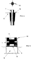
- Fig. 1 illustrates a pile 1 suspended by a suspension means 2 which is used for locating and correctly orienting the pile for introduction/driving into the formation 5.
- the pile can be equipped with a pipe socket 3 for evacuation and filling, respectively, of water, and perforations with filter 4 allowing transport of fluid from the formation into the tube and vice versa.
- the filter inhibits solid particles transported with the water.
- the pile has a preferably circular cross section, but could also have a different shape. However, it is essential that the pile is substantially an open tube.
- Fig. 2a shows the same pile in a down driven condition. It is not shown how the pile is driven down, and this is not a part of the invention.
- a pile driver or a vibrating hammer may be used, but also other techniques can be utilized, as mentioned with reference to Fib. 2b below
- Fig. 2b shows a vertical section of the upper segment of the pile in Fig. 1 and 2a.
- the vibrator 6 is suspended so that it can be driven in the horizontal plane in order to generate shear waves in a plurality of directions.
- the actual rotation mechanism is not shown.
- a plate 7 is attached in the interior of the pile at a height that is substantial equivalent to the level of the formation.
- a filter 8 of geotextile or geocomposite can be provided right under the plate 7 in connection with the tube end 3 for preventing solid particles from entering an evacuation pump (not shown), which is used to evacuate water from the room between the sediments and the plate down in the sea bed. The difference in the pressure arising during this process will lead the tube to be pressed into the sea bed. The tube will then be filled with bottom sediments and the vertical movement is stopped when the shut-in water is pumped out and the plate touches the sea bed.
- the tube can be installed completely by only using pumping.
- extra measures should be taken, as for example using a subsea hammer in a per se known manner.
- Filters of suitable materials may be located in the openings 4 of the pile in order to prevent movement of solid particles with the water in to or out from the pile.
- Fig. 3 illustrates a schematic section of a suitable generator for shear waves, of a hydraulic, power-assisted vibrator type. This is not a part of the invention, but is shown for understanding.
- Hydraulic oil is supplied at 14 and is alternatively lead down to the left and the right, respectively, of the piston 11 which is fixed in relation to the pile by means of connections 17. Since the piston is fixed, the oil pressure in the cylinder 10 hits back and forth in the rhythm determined by the servo valve, and thus transfers shear forces to the pile which are horizontally polarized.
- Typical oscillation mass for such a vibrator can be up to two tons.
- the pile shown in Fig. 4 is equipped with radially extending flanges 18 which gives a larger contact area between pile and formation, and will thus further contribute to achieving a stable anchoring of the pile to the formation.
- This variant can, of course, be combined with the one that contains an inner stop plate.
- Fig. 5 illustrates an embodiment where the vibrator is mounted inside a housing 19, which is located at the top of a previously installed pile.
- the vibrator housing should be adapted to the pile in which it is to be mounted in advance.
- the vibrator housing 19 and the vibrator near the lowermost distal end tip of the pile 1, as illustrated in Fig. 6, or at an intermediate level between pile end and pile top.
- the reason for the above variations is to transfer as much energy as possible from the vibrator to the firmer, deeper structure if, for example, the uppermost layer of sediment is very soft.
- the installation process of pile and vibrator can be achieved by the pile first being penetrated and the enclosed soil being evacuated before the vibrator unit is mounted, or both being installed together as one unit. The latter assumes that the lowermost end is closed and that the sediments are sufficiently soft that penetration can be performed with conventional equipment for use in marine enviro ents.
- Vibroseis technique An appropriate way of monitoring a formation is to let the shear waves sweep through a defined area of frequency over a certain period, the so-called Vibroseis technique. Information as to of the condition of the formation is achieved by cross correlation of the transmitted signal with the measured signal. Theory for this technique is well known, and is not a part of the invention.
- a problem can occur in the shape of local over pressure in the pore, in the vicinity of the pile when it is put in vibrations.
- the mass in the vicinity of the pile can be loosened, so that the shear waves are not transferred to the ground in an effective way.
- the evacuating pump can run continuously, so that a lasting under pressure is developed in the tube and to a certain degree outside of it and a controlled transport of water is achieved from the formation into the tube (pile) through the openings 4 and out through the evacuation pump.
Landscapes
- Engineering & Computer Science (AREA)
- Remote Sensing (AREA)
- Physics & Mathematics (AREA)
- Life Sciences & Earth Sciences (AREA)
- Acoustics & Sound (AREA)
- Environmental & Geological Engineering (AREA)
- Geology (AREA)
- General Life Sciences & Earth Sciences (AREA)
- General Physics & Mathematics (AREA)
- Geophysics (AREA)
- Geophysics And Detection Of Objects (AREA)
Description
Claims (6)
- Method for generating seismic shear waves in an underground formation (5) for mapping of geological resources, in which a tubular pile (1) is installed into the formation by being driven or by other means put into the formation which tubular pile (1) is influenced by an oscillating mass acting in the horizontal plane pile into transversal vibrations which transmit horizontally polarized shear waves into the formation,
characterized by the pile (1) having an open tip which allows the pile (1) to be soil-filled with bottom sediments, and in which a plate (7) is situated in the tubular pile (1) at a level that is flush with the formation surface and arranged to prohibit the pile (1) from penetrating further into the formation. - Method according to Claim 1,
characterized by a vibration source (6) that is mounted inside the pile (1) which is capable of turning about a horizontal axis so that it may vibrate along the vertical axis and generate compressional waves at the pile tip. - Method according to Claim 1,
characterized by a vibration source (6) that is mounted inside the pile (1) which enables the source to turn in the horizontal plane - Method according to above claims,
characterized by that the transversal vibrations are generated in one horizontal direction during an initial period and then in another horizontal direction to get a best possible picture of the formation (5). - Method according to Claim 4,
characterized by that the said directions are in a given angle to each other. - Method according to the above claims,
characterized by that a negative differential pressure inside the pile (1) is maintained to reduce possible pore water pressure in the formation (5) around the pile (1) during vibration.
Applications Claiming Priority (3)
| Application Number | Priority Date | Filing Date | Title |
|---|---|---|---|
| NO964026A NO304203B1 (en) | 1996-09-24 | 1996-09-24 | Procedure for generating seismic waves |
| NO964026 | 1996-09-24 | ||
| PCT/NO1997/000256 WO1998013707A1 (en) | 1996-09-24 | 1997-09-22 | Method for generating seismic shearing waves in a subterranean formation |
Publications (2)
| Publication Number | Publication Date |
|---|---|
| EP0954759A1 EP0954759A1 (en) | 1999-11-10 |
| EP0954759B1 true EP0954759B1 (en) | 2003-05-02 |
Family
ID=19899865
Family Applications (1)
| Application Number | Title | Priority Date | Filing Date |
|---|---|---|---|
| EP97943229A Expired - Lifetime EP0954759B1 (en) | 1996-09-24 | 1997-09-22 | Method for generating seismic shearing waves in a subterranean formation |
Country Status (8)
| Country | Link |
|---|---|
| US (1) | US6105712A (en) |
| EP (1) | EP0954759B1 (en) |
| AU (1) | AU718613B2 (en) |
| CA (1) | CA2266451A1 (en) |
| DE (1) | DE69721568D1 (en) |
| DK (1) | DK0954759T3 (en) |
| NO (1) | NO304203B1 (en) |
| WO (1) | WO1998013707A1 (en) |
Families Citing this family (8)
| Publication number | Priority date | Publication date | Assignee | Title |
|---|---|---|---|---|
| NO310747B2 (en) | 1999-12-10 | 2001-08-20 | Norges Geotekniske Inst | Procedure for generating seismic shear waves in the seabed |
| FR2818754B1 (en) * | 2000-12-21 | 2004-06-18 | Inst Francais Du Petrole | DEVICE FOR GENERATING FOCUSED ELASTIC WAVES IN A MATERIAL MEDIUM SUCH AS THE BASEMENT, AND METHOD FOR ITS IMPLEMENTATION |
| US7063144B2 (en) * | 2003-07-08 | 2006-06-20 | Klamath Falls, Inc. | Acoustic well recovery method and device |
| NO20041565L (en) * | 2004-04-16 | 2005-10-17 | Selantic | Seismic subsea source and method for 4-component seismic |
| US7059403B2 (en) * | 2004-11-11 | 2006-06-13 | Klamath Falls, Inc. | Electroacoustic method and device for stimulation of mass transfer processes for enhanced well recovery |
| NO20045036L (en) * | 2004-11-19 | 2006-05-22 | Ngi | Skjaerbolgegenerator |
| DE102005024367B4 (en) * | 2005-05-27 | 2013-08-22 | Helmholtz-Zentrum Potsdam Deutsches GeoForschungsZentrum - GFZ Stiftung des Öffentlichen Rechts des Landes Brandenburg | Seismic source and method of generating shear seismic waves |
| CA2694633C (en) * | 2007-08-10 | 2015-09-01 | Marvin L. Johnson | Bottom referenced vibratory sources for shallow water acquisition |
Family Cites Families (3)
| Publication number | Priority date | Publication date | Assignee | Title |
|---|---|---|---|---|
| US4310066A (en) * | 1980-02-22 | 1982-01-12 | Won Ihn J | Torsional shear wave generator |
| US4867096A (en) * | 1986-12-12 | 1989-09-19 | Conoco Inc. | Tubular shear wave source |
| US5128906A (en) * | 1991-06-06 | 1992-07-07 | Conoco Inc. | Deep penetrating shear-wave seismic vibratory source for use in marine environments |
-
1996
- 1996-09-24 NO NO964026A patent/NO304203B1/en not_active IP Right Cessation
-
1997
- 1997-09-22 DK DK97943229T patent/DK0954759T3/en active
- 1997-09-22 WO PCT/NO1997/000256 patent/WO1998013707A1/en not_active Ceased
- 1997-09-22 AU AU44752/97A patent/AU718613B2/en not_active Ceased
- 1997-09-22 EP EP97943229A patent/EP0954759B1/en not_active Expired - Lifetime
- 1997-09-22 CA CA002266451A patent/CA2266451A1/en not_active Abandoned
- 1997-09-22 DE DE69721568T patent/DE69721568D1/en not_active Expired - Lifetime
- 1997-09-22 US US09/269,169 patent/US6105712A/en not_active Expired - Lifetime
Also Published As
| Publication number | Publication date |
|---|---|
| AU4475297A (en) | 1998-04-17 |
| DK0954759T3 (en) | 2003-08-25 |
| WO1998013707A1 (en) | 1998-04-02 |
| AU718613B2 (en) | 2000-04-20 |
| EP0954759A1 (en) | 1999-11-10 |
| CA2266451A1 (en) | 1998-04-02 |
| DE69721568D1 (en) | 2003-06-05 |
| NO964026D0 (en) | 1996-09-24 |
| US6105712A (en) | 2000-08-22 |
| NO304203B1 (en) | 1998-11-09 |
| NO964026L (en) | 1998-03-25 |
Similar Documents
| Publication | Publication Date | Title |
|---|---|---|
| US4128011A (en) | Investigation of the soundness of structures | |
| US4003017A (en) | Continuous bit positioning system | |
| JP5352674B2 (en) | Reverse vertical borehole seismic survey by impact measurement in both directions during excavation | |
| JP5818355B2 (en) | Well position determination method using hypocenter and seismic receiver | |
| US11619018B2 (en) | Soil probing device having built-in generators and detectors for compressional waves and shear waves | |
| EP1002934A2 (en) | Drilling apparatus | |
| AU718613B2 (en) | Method for generating seismic shearing waves in a subterranean formation | |
| US5124956A (en) | Geophone with depth sensitive spikes | |
| Broms | Soil sampling in Europe: state-of-the-art | |
| Angemeer et al. | Pile load tests in calcareous soils conducted in 400 feet of water from a semi-submersible exploration rig | |
| CA2743716C (en) | Method and system for fixing an element in a borehole | |
| US5758539A (en) | Logging method and system for measuring mechanical parameters of the formations crossed through by a borehole | |
| Deflandre et al. | Microseismic surveying and repeated VSPs for monitoring an underground gas storage reservoir using permanent geophones | |
| CN110905012B (en) | Building pile foundation detection method | |
| US20140116726A1 (en) | Downhole Sensor and Method of Coupling Same to A Borehole Wall | |
| Ferguson et al. | Seafloor cone penetrometer for deep penetration measurements of ocean sediment strength | |
| Sheshpari et al. | New frontiers in the offshore geotechnics and foundation design | |
| Stokoe et al. | Development of a bottom-hole device for offshore shear wave velocity measurement | |
| Campanella et al. | Seismic cone penetration testing in the near offshore of the MacKenzie Delta | |
| Sullivan | North sea foundation investigation techniques | |
| Yu | A Deep Rock Cavern Captures Stormwater | |
| Chari | Instrumentation problems related to determining geotechnical properties of ocean sediments | |
| CN121781568A (en) | A static cone penetration probe, a static cone penetration device, and a static cone penetration method. | |
| JPS638273B2 (en) | ||
| Ingram et al. | Geotechnical-Acoustical Analysis of Marine Sediments: A Review on the State of The Technology |
Legal Events
| Date | Code | Title | Description |
|---|---|---|---|
| PUAI | Public reference made under article 153(3) epc to a published international application that has entered the european phase |
Free format text: ORIGINAL CODE: 0009012 |
|
| 17P | Request for examination filed |
Effective date: 19990319 |
|
| AK | Designated contracting states |
Kind code of ref document: A1 Designated state(s): DE DK ES FR GB IE IT NL PT |
|
| 17Q | First examination report despatched |
Effective date: 20010925 |
|
| RIC1 | Information provided on ipc code assigned before grant |
Free format text: 7G 01V 1/053 A, 7G 01V 1/155 B |
|
| GRAH | Despatch of communication of intention to grant a patent |
Free format text: ORIGINAL CODE: EPIDOS IGRA |
|
| GRAH | Despatch of communication of intention to grant a patent |
Free format text: ORIGINAL CODE: EPIDOS IGRA |
|
| GRAA | (expected) grant |
Free format text: ORIGINAL CODE: 0009210 |
|
| AK | Designated contracting states |
Designated state(s): DE DK ES FR GB IE IT NL PT |
|
| PG25 | Lapsed in a contracting state [announced via postgrant information from national office to epo] |
Ref country code: NL Free format text: LAPSE BECAUSE OF FAILURE TO SUBMIT A TRANSLATION OF THE DESCRIPTION OR TO PAY THE FEE WITHIN THE PRESCRIBED TIME-LIMIT Effective date: 20030502 Ref country code: IT Free format text: LAPSE BECAUSE OF FAILURE TO SUBMIT A TRANSLATION OF THE DESCRIPTION OR TO PAY THE FEE WITHIN THE PRESCRIBED TIME-LIMIT;WARNING: LAPSES OF ITALIAN PATENTS WITH EFFECTIVE DATE BEFORE 2007 MAY HAVE OCCURRED AT ANY TIME BEFORE 2007. THE CORRECT EFFECTIVE DATE MAY BE DIFFERENT FROM THE ONE RECORDED. Effective date: 20030502 Ref country code: FR Free format text: LAPSE BECAUSE OF FAILURE TO SUBMIT A TRANSLATION OF THE DESCRIPTION OR TO PAY THE FEE WITHIN THE PRESCRIBED TIME-LIMIT Effective date: 20030502 |
|
| REG | Reference to a national code |
Ref country code: GB Ref legal event code: FG4D |
|
| REF | Corresponds to: |
Ref document number: 69721568 Country of ref document: DE Date of ref document: 20030605 Kind code of ref document: P |
|
| REG | Reference to a national code |
Ref country code: IE Ref legal event code: FG4D |
|
| PG25 | Lapsed in a contracting state [announced via postgrant information from national office to epo] |
Ref country code: PT Free format text: LAPSE BECAUSE OF FAILURE TO SUBMIT A TRANSLATION OF THE DESCRIPTION OR TO PAY THE FEE WITHIN THE PRESCRIBED TIME-LIMIT Effective date: 20030804 |
|
| PG25 | Lapsed in a contracting state [announced via postgrant information from national office to epo] |
Ref country code: DE Free format text: LAPSE BECAUSE OF FAILURE TO SUBMIT A TRANSLATION OF THE DESCRIPTION OR TO PAY THE FEE WITHIN THE PRESCRIBED TIME-LIMIT Effective date: 20030805 |
|
| PG25 | Lapsed in a contracting state [announced via postgrant information from national office to epo] |
Ref country code: ES Free format text: LAPSE BECAUSE OF FAILURE TO SUBMIT A TRANSLATION OF THE DESCRIPTION OR TO PAY THE FEE WITHIN THE PRESCRIBED TIME-LIMIT Effective date: 20030813 |
|
| REG | Reference to a national code |
Ref country code: DK Ref legal event code: T3 |
|
| NLV1 | Nl: lapsed or annulled due to failure to fulfill the requirements of art. 29p and 29m of the patents act | ||
| PLBE | No opposition filed within time limit |
Free format text: ORIGINAL CODE: 0009261 |
|
| STAA | Information on the status of an ep patent application or granted ep patent |
Free format text: STATUS: NO OPPOSITION FILED WITHIN TIME LIMIT |
|
| 26N | No opposition filed |
Effective date: 20040203 |
|
| EN | Fr: translation not filed | ||
| PGFP | Annual fee paid to national office [announced via postgrant information from national office to epo] |
Ref country code: DK Payment date: 20110926 Year of fee payment: 15 |
|
| PGFP | Annual fee paid to national office [announced via postgrant information from national office to epo] |
Ref country code: IE Payment date: 20120920 Year of fee payment: 16 Ref country code: GB Payment date: 20120920 Year of fee payment: 16 |
|
| REG | Reference to a national code |
Ref country code: DK Ref legal event code: EBP Effective date: 20130930 |
|
| GBPC | Gb: european patent ceased through non-payment of renewal fee |
Effective date: 20130922 |
|
| REG | Reference to a national code |
Ref country code: IE Ref legal event code: MM4A |
|
| PG25 | Lapsed in a contracting state [announced via postgrant information from national office to epo] |
Ref country code: GB Free format text: LAPSE BECAUSE OF NON-PAYMENT OF DUE FEES Effective date: 20130922 Ref country code: IE Free format text: LAPSE BECAUSE OF NON-PAYMENT OF DUE FEES Effective date: 20130922 |
|
| PG25 | Lapsed in a contracting state [announced via postgrant information from national office to epo] |
Ref country code: DK Free format text: LAPSE BECAUSE OF NON-PAYMENT OF DUE FEES Effective date: 20130930 |