EP0954628B1 - Warp changing apparatus - Google Patents
Warp changing apparatus Download PDFInfo
- Publication number
- EP0954628B1 EP0954628B1 EP98900946A EP98900946A EP0954628B1 EP 0954628 B1 EP0954628 B1 EP 0954628B1 EP 98900946 A EP98900946 A EP 98900946A EP 98900946 A EP98900946 A EP 98900946A EP 0954628 B1 EP0954628 B1 EP 0954628B1
- Authority
- EP
- European Patent Office
- Prior art keywords
- warp
- support
- changing apparatus
- reed
- loom
- Prior art date
- Legal status (The legal status is an assumption and is not a legal conclusion. Google has not performed a legal analysis and makes no representation as to the accuracy of the status listed.)
- Expired - Lifetime
Links
- 235000014676 Phragmites communis Nutrition 0.000 claims description 28
- 238000000034 method Methods 0.000 claims description 4
- 238000009941 weaving Methods 0.000 description 4
- 238000009434 installation Methods 0.000 description 3
- 244000089486 Phragmites australis subsp australis Species 0.000 description 1
- 230000006378 damage Effects 0.000 description 1
- 239000004744 fabric Substances 0.000 description 1
- 238000009730 filament winding Methods 0.000 description 1
- 238000012986 modification Methods 0.000 description 1
- 230000004048 modification Effects 0.000 description 1
- 230000001105 regulatory effect Effects 0.000 description 1
- 230000000284 resting effect Effects 0.000 description 1
- 238000005491 wire drawing Methods 0.000 description 1
- 239000002759 woven fabric Substances 0.000 description 1
Images


Classifications
-
- D—TEXTILES; PAPER
- D03—WEAVING
- D03J—AUXILIARY WEAVING APPARATUS; WEAVERS' TOOLS; SHUTTLES
- D03J1/00—Auxiliary apparatus combined with or associated with looms
- D03J1/001—Cloth or warp beam replacement
Definitions
- the present invention relates to a warp changing apparatus.
- Woven fabrics are woven on the loom by passing the weft yarns through a shed formed between adjacent warp yarns, the warp yarns running perpendicular to the length of the loom. These warp yarns are threaded through healds which each consist of a vertically oriented wire having an eyelet at the base thereof through which an individual warp yarn is threaded. During weaving a shed is formed by raising a heald and consequently the warp yarn threaded through the heald eyelet. After passing through the healds the warp yarns also pass through a reed to ensure a straight path for these yarns.
- Warp yarns are stored on cannisters, often referred to as cans, which are large spools.
- the cans are mounted on a beam running parallel with and behind the loom.
- the warp yam is loaded onto the cans in the so-called warping process in which a plurality of yarns are fed onto each can from a series of individual bobbins. These yarns are fed from the bobbins through a reed and are then wound onto the can.
- the cans are stored in the loom on two beams, one above the other, with each beam being made up of smaller shafts each supporting two cans.
- a mobile gantry is moved into position behind the loom to support the empty cans whilst the shaft is removed.
- the empty cans are then loaded onto carts in order to return them to the warping area.
- Full cans are then moved into position and the shaft re-inserted back into the pair of cans. This is repeated along the entire length of the loom which may contain in the region of 30 warp cans on one beam. Warp cans need to be replaced on both the upper and lower beams, with the operators replacing both the upper and lower can pairs in an alternating fashion. This is a very time consuming task taking around 8 to 16 hours per loom.
- a new loom design aims to solve this problem by providing larger beams with a central flange.
- the beam is at least 5.0m in length having a 300-700 mm diameter shaft holding up to 30 cans (e.g. 27 cans split into sections of 13 and 14 cans on either side of the central flange) or a full beam.
- This type of loom allows the healds to be lowered into the top of the loom.
- a standard loom does not allow this because the healds are loaded from underneath, since a so-called superstructure is normally present in the top of the loom, running along its entire length, to weigh down the loom and prevent it from lifting up during weaving.
- the support structure for the top beam also lifts back to aid installation of the bottom beam
- U.S. Patent 4,910,837 (Fujimoto et al) describes a warp beam carriage towed by an unmanned tractor, and guided by tracks parallel to the back of the loom, being halted automatically and the required positions to exchange a loaded beam for an empty beam. This installation is inflexible, and if a tractor fails on the track, it cannot be bypassed to continue with loading.
- a warp changing apparatus comprising a warp beam support and a hoverpad operative to facilitate or aid movement of the warp beam support along the ground.
- the hoverpad is located at the underside of the base of the warp beam support.
- One or more hoverpads may be used.
- the hoverpad or hoverpads are ideally located substantially in the middle of the underside of the warp beam support. Wheels and/or rollers may further be provided at the underside of the warp beam support.
- a warp changing apparatus of the invention further comprises a warp beam support, a reed support and a heald support, the reed support and heald support being mounted on an arm such that the reed support and heald support may be moved between a raised position and a lowered position.
- the arm preferably comprises two pivot joints which facilitates the collapse of the arm in a manner which does not affect the orientation of the reed support and heald support.
- the reed support and heald support preferably comprise a housing.
- a warp changing apparatus may further comprise a warp beam support, wherein the warp changing apparatus further comprises at least one drive shaft operable to cause rotation of at least one cannister or roll beam located on the warp beam so as to adjust the tension of the warp wrapped around the said cannister or roll beam, wherein means are provided for causing rotation of the drive shaft, said means being located on the warp beam support at a location that does not obstruct access to the support by the beam.
- an individual drive wheel is provided on the shaft for engagement with each cannister to be located thereon.
- the apparatus of the invention facilitates a far quicker change of warp yarns, taking less than 24 hours, compared with the standard 1-3 weeks using conventional apparatus.
- Hoverpad trucks enable heavy loads of between 10 - 30 tonnes to be easily manoeuvred by a single operator.
- the trucks are relatively small and are therefore easy to store and guide around the factory, and are useful for transporting any item of heavy machinery, or component such as rollers, shafts, beams, etc., for instance during filament winding or wire drawing.
- packages of healds, reeds and drawn-in yarns can be removed as single units. For example, if a relatively uncommon warp yarn was being woven on the loom, rather than having the loom sit idle for weeks waiting for another order, the partly-full beams could be removed together with the reed, healds and yarns (still in the healds and reed), due to the collapsible arm and ability to allow for giving or taking off slack on the warp yarns during manoeuvring.
- the warp yarns are cut between the heald and cans, allowing the heald/reed, drawn-in yarns and partly-full cans to be stored separately for later use when these entities would be replaced in the loom and the yarns knotted together, saving the need to re-draw in all the yarns through the healds and reed again.
- the collapsible bracket avoids the need to lift the bottom beam to allow the truck to leave the loom, and it can also be removed to allow the truck to transport cans or beam-supported cans to conventional looms.
- Cannisters are easy to load onto the trucks, especially since they are not end-driven. Therefore there is no gear box or bearing at the end of the trucks to drive the rollers. These would normally have to be removed before putting the cans on the shaft.
- the warp changing apparatus may be used for example in weaving papermaking fabrics or weaving of carpets.
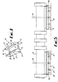
- a warp changing apparatus 10 comprises a truck comprising a base 11 and four vertical walls 12, 13, 14, 15.
- a semi-circular recess 16 is provided in each of the opposing side walls 12,13. No recess is provided in the front and rear upstanding walls.
- a wheel 17 is provided at each comer of the base of the track.
- a hoverpad 18 is provided at the base of the truck.
- the can 19 comprises a tubular spool having flanges on either side thereof.
- the spool is operative to be received on the beam with a snug fit.
- a channel is provided in the interior spool wall which defines the aperture through the tube.
- a groove is also provided in the beam.
- a keyway is operative to be received in the said channel and is affixed thereto by way of an alun key lock. When the keyway is received in the groove and channel simultaneously, the cans are restrained from rotation about the beam.
- the aperture through the can is aligned with the beam.
- the keyway is removed from the can and the can is located on the beam. At this stage the can may rotate freely about the beam. The keyway is now locked into position to prevent this rotation. All of the cans, but one are now located on that end of the beam.
- the beam has a flange provided at roughly the centre of its longitudinal axis. The final can for that end of the beam is simply moved by the truck until the aperture through the can is aligned with the end of the beam. This final can is then simply slipped over the shaft and is locked in position by its keyway. This final can rests on the truck and therefore the truck supports one end of the beam for transportation.
- a truck is also provided for supporting the other end of the beam. It is noted that during the leading operation the horizontal position of the beam is regulated by jacks beneath it.
- the jacks may be located on the truck or may be separate units located on the ground.
- a bracket 20 is illustrated at the front of and above the can in the truck.
- the bracket has three sections 21,22,23.
- the lower section 21 of the bracket is fixed to the front of the truck.
- the base of the middle section 22 of the bracket is secured to the top of the lower section 21 by a pivot joint such that the middle section may move between a vertical position as shown in fig. 1 to a horizontal position as shown in fig.2.
- the base of the upper section 23 of the bracket is secured to the top of the middle section of the bracket via a pivot such that the upper section maintains its vertical orientation as the middle section of the bracket moves between the vertical and horizontal positions.
- the upper section of the bracket comprises a housing 24 for the reed 25 and healds 26 of the warp system.
- the yarns from the charged cans are located on the truck and may be fed to the healds 26 and reed 25 in the bracket housing 24.
- two people would generally carry out this task.
- the work may be done by two operators sitting on chairs rather than being precariously balanced on equipment inside the loom as in the prior art systems. This is a frequent cause of injuries and strains.
- the truck may be moved forward on the hoverpad 18 or hoverpads onto the back of the loom. This allows large loads to be moved by a single operator.
- An overhead crane is used to lift the reed 25 and healds 26 out of the bracket into the loom. During the lifting of the reed 25 and healds 26 the beams are rotated to move the yarns slack to thereby facilitate the manoeuvring of the reed 25 and healds 26 into position.
- the healds 26 are preferably locked into place by simple snap-fit connections.
- the reed 25 is installed and clamped into position.
- drive shafts 27,28 are provided inside the truck adjacent the front and rear walls 14,15 of the truck.
- a plurality of wheels 29 are provided on the drive shafts 27,28.
- One wheel 29 is provided on each drive shaft for engagement with each can.
- the two shafts 27,28 are driven by one or more drive motors which are located at the rear of the truck so as not to prevent access to the truck from the sides 12,13 of the truck and thus impede beam location and removal.
- the drive shafts 27,28 may be driven in a clockwise or anti-clockwise direction so as to give slack or take off slack in the warp yarns.
- the drive shaft mechanism In order to remove the tracks from the loom the drive shaft mechanism is used to take off any slack in the warp yarns.
- the bracket for the healds and reed is collapsed in to the position illustrated in fig. 2 allowing the trucks to be pulled out of the loom.
- the beam supported by the trucks is then lifted by the shaft ends using an overhead crane and then it is lowered so that the ends of the shaft come to rest against brackets at each end of the loom.
- the hoverpad is then deflated.
- the first pair of trucks are now resting on their wheels and can be removed from the loom.
- the support for the top beam which had been lifted up to make access to the back of the loom easier, is now is lowered back into position and locked against the bottom beam support.
- the top beam is moved adjacent the back of the loom on hoverpads and the overhead crane is used to raise and lower the beam into the brackets.
- the truck is then removed by deflating the hoverpad and wheeling the truck away. During these steps the cans may be driven to give or take slack as required.
Landscapes
- Engineering & Computer Science (AREA)
- Textile Engineering (AREA)
- Auxiliary Weaving Apparatuses, Weavers' Tools, And Shuttles (AREA)
- Looms (AREA)
- Treatment Of Fiber Materials (AREA)
- Agricultural Chemicals And Associated Chemicals (AREA)
- Medicines Containing Plant Substances (AREA)
- Bidet-Like Cleaning Device And Other Flush Toilet Accessories (AREA)
Abstract
Description
Claims (13)
- A warp changing apparatus comprising a warp beam support (10) characterised in that it further comprises a hoverpad (18) operative to facilitate or aid movement of the warp beam support along the ground.
- A warp changing apparatus according claim 1, wherein the hoverpad (18) is located at the underside of the base of the warp beam support (10).
- A warp changing apparatus according to claim 1 or claim 2, wherein one or more hoverpads (18) are used.
- A warp changing apparatus according to any preceding claim, wherein the hoverpad or hoverpads (18) are located substantially in the middle of the warp beam support (10).
- A warp changing apparatus according to any preceding claim, wherein wheels and/or rollers (17) are provided at the underside of the warp beam support (10).
- A warp changing apparatus according to claim 1 further comprising a reed support and a heald support (24), the reed support and heald support (24) being mounted on an arm (21) such that the reed support and heald support (24) may be moved between a raised position and a lowered position.
- A warp changing apparatus according to claim 6, wherein the arm (21) comprises two pivot joints which facilitates the collapse of the arm (21) in a manner which does not affect the orientation of the reed support and heald support (24).
- A warp changing apparatus according to claim 6 or claim 7, wherein the reed support and heald support comprise a housing (24).
- A warp changing apparatus according to claim 1 further comprising at least one drive shaft (29) operable to cause rotation of at least one cannister (19) located on the warp beam so as to adjust the tension of the warp wrapped around the said cannister (19), wherein means are provided for causing rotation of the drive shaft (28), said means being located on the warp beam support at a location that does not obstruct access to the support by the beam.
- A warp changing apparatus according to claim 9, wherein an individual drive wheel is provided on the shaft for engagement with each cannister to be located thereon.
- A method of changing the warp on a loom comprising the step of moving a warp beam support, characterised in that the movement is facilitated by a hoverpad.
- A method of changing the warp on a loom according to claim 11 further comprising the steps of mounting a heald support and a reed support on an arm, said arm being moveable between a raised position and a lowered position and wherein the orientation of the reed support and heald support is not affected by the movement of the arm.
- A method of changing the warp on a loom according to claim 11 further comprising the steps of rotation of a cannister or roll beam located on the warp beam so as to adjust the tension of the warp wrapped around the cannister, said warp beam being supported on a warp beam support including said hoverpad, rotation of the cannister caused by a drive shaft operable to cause rotation of at least one cannister or roll beam, wherein means for causing rotation of the drive shaft are located on the warp beam support at a location which does not obstruct access to the support by the beam.
Applications Claiming Priority (3)
| Application Number | Priority Date | Filing Date | Title |
|---|---|---|---|
| GB9701446 | 1997-01-24 | ||
| GBGB9701446.8A GB9701446D0 (en) | 1997-01-24 | 1997-01-24 | Warp changing apparatus |
| PCT/GB1998/000198 WO1998032905A1 (en) | 1997-01-24 | 1998-01-22 | Warp changing apparatus |
Publications (2)
| Publication Number | Publication Date |
|---|---|
| EP0954628A1 EP0954628A1 (en) | 1999-11-10 |
| EP0954628B1 true EP0954628B1 (en) | 2002-05-22 |
Family
ID=10806518
Family Applications (1)
| Application Number | Title | Priority Date | Filing Date |
|---|---|---|---|
| EP98900946A Expired - Lifetime EP0954628B1 (en) | 1997-01-24 | 1998-01-22 | Warp changing apparatus |
Country Status (7)
| Country | Link |
|---|---|
| US (1) | US6314628B1 (en) |
| EP (1) | EP0954628B1 (en) |
| JP (1) | JP2001508840A (en) |
| AT (1) | ATE217916T1 (en) |
| DE (1) | DE69805501D1 (en) |
| GB (1) | GB9701446D0 (en) |
| WO (1) | WO1998032905A1 (en) |
Families Citing this family (6)
| Publication number | Priority date | Publication date | Assignee | Title |
|---|---|---|---|---|
| US20060239153A1 (en) * | 2005-04-25 | 2006-10-26 | Mediatek Incorporation | Methods and circuits for automatic power control |
| US7318456B2 (en) * | 2005-04-25 | 2008-01-15 | Massachusetts Institute Of Technology | Modular weaving system with individual yarn control |
| US7178558B2 (en) | 2005-04-25 | 2007-02-20 | Massachusetts Institute Of Technology | Modular weaving for short production runs |
| DE102005019906B3 (en) * | 2005-04-29 | 2006-03-30 | Lindauer Dornier Gmbh | Loom with releasable coupling between drive and warp beam, based on indentations in supporting wall through which screws can pass so that driver is screwable to or unscrewable from warp beam flange |
| DE502007004733D1 (en) * | 2007-09-12 | 2010-09-23 | Groz Beckert Kg | Transport trolley for needle boards |
| CN107839743A (en) * | 2017-11-28 | 2018-03-27 | 四川玉扬纺织有限公司 | The warp beam transshipment acitivity weaved between each workshop |
Family Cites Families (14)
| Publication number | Priority date | Publication date | Assignee | Title |
|---|---|---|---|---|
| US1304846A (en) * | 1919-05-27 | Wabp-repi | ||
| US1304875A (en) * | 1919-05-27 | Wabp-beplenishing machine | ||
| US2579730A (en) * | 1949-02-19 | 1951-12-25 | Noah W Eurey | Warp beam and harness frame transporting truck |
| US2706056A (en) * | 1952-01-23 | 1955-04-12 | United Merchants & Mfg | Warp beam truck |
| US2994939A (en) * | 1957-05-15 | 1961-08-08 | Us Rubber Co | Apparatus for handling warp beams |
| CH440170A (en) * | 1966-03-08 | 1967-07-15 | Zellweger Uster Ag | Trolley for the transport of warp warps, which consist of at least two axially aligned warp beams |
| GB1292801A (en) * | 1968-07-17 | 1972-10-11 | Tracked Hovercraft Ltd | Linear motor reaction rail assembly |
| US3703869A (en) * | 1970-07-28 | 1972-11-28 | Tracked Hovercraft Ltd | Track guided vehicle |
| DE2635524C3 (en) * | 1976-08-06 | 1981-12-24 | System Schultheis GmbH & Co, Maschinenfabrik, 6400 Fulda | Warp beam lifting and transport trolleys for twin warp beams |
| US4630543A (en) * | 1983-12-16 | 1986-12-23 | Otis Elevator Company | Bogie for cable-drawn vehicle |
| US4910837A (en) | 1986-03-17 | 1990-03-27 | Kabushiki Kaisha Toyoda Jidoshokki Seisakusho | Looming apparatus for a loom |
| DE4234563C2 (en) * | 1992-10-14 | 1996-02-29 | Dornier Gmbh Lindauer | Device for temporary storage of a warp change system prepared for weaving |
| DE4310838C2 (en) * | 1993-04-02 | 1996-03-14 | Dornier Gmbh Lindauer | Carrying device for the weaving harness of a weaving machine |
| BE1008059A3 (en) * | 1994-02-02 | 1996-01-03 | Picanol Nv | METHOD AND APPARATUS FOR DRAWING ON warp threads. |
-
1997
- 1997-01-24 GB GBGB9701446.8A patent/GB9701446D0/en active Pending
-
1998
- 1998-01-22 AT AT98900946T patent/ATE217916T1/en not_active IP Right Cessation
- 1998-01-22 WO PCT/GB1998/000198 patent/WO1998032905A1/en not_active Ceased
- 1998-01-22 EP EP98900946A patent/EP0954628B1/en not_active Expired - Lifetime
- 1998-01-22 DE DE69805501T patent/DE69805501D1/en not_active Expired - Lifetime
- 1998-01-22 JP JP53172598A patent/JP2001508840A/en active Pending
- 1998-01-22 US US09/341,674 patent/US6314628B1/en not_active Expired - Fee Related
Also Published As
| Publication number | Publication date |
|---|---|
| ATE217916T1 (en) | 2002-06-15 |
| JP2001508840A (en) | 2001-07-03 |
| GB9701446D0 (en) | 1997-03-12 |
| US6314628B1 (en) | 2001-11-13 |
| DE69805501D1 (en) | 2002-06-27 |
| WO1998032905A1 (en) | 1998-07-30 |
| EP0954628A1 (en) | 1999-11-10 |
Similar Documents
| Publication | Publication Date | Title |
|---|---|---|
| EP0407162B1 (en) | Carriage for the transportation of a cylindrical object | |
| US4910837A (en) | Looming apparatus for a loom | |
| JPWO1999028230A1 (en) | Crane equipment | |
| EP0567497B1 (en) | Yarn delivery | |
| US6314628B1 (en) | Warp changing apparatus | |
| CN204702277U (en) | Loom replacements carrying device | |
| JPH0671982B2 (en) | Winder installation method and winder installation carriage | |
| US4858746A (en) | Method and apparatus for transporting articles | |
| WO2009092861A1 (en) | Method for handling empty winding shafts delivered to a fibrous web winder | |
| KR940011301B1 (en) | Method of automatically servicing winding apparatus in multi-station textile machines | |
| US4941625A (en) | Creel for the simultaneous changing of reels of metallic wire | |
| JPH06104938B2 (en) | Preliminary roving winding conveying method between roving and spinning processes | |
| US20250243025A1 (en) | Assembly for Handling Reel Spools and a Reel-up - Unwinder System for a Fiber Web Production Line | |
| JP2660977B2 (en) | Roving conveyor | |
| JP2552259B2 (en) | Transfer device for roving bobbin | |
| CA1127194A (en) | Apparatus for handling bobbins | |
| JPS63295729A (en) | Apparatus for exchanging transfer device in preparatory roving pirn transfer system | |
| EP2578523A1 (en) | Arrangement for transferring loads, in particular elongate loads, in connection with production of fiber webs | |
| JP2517819B2 (en) | Ceiling carrier transport system | |
| JPS6323105B2 (en) | ||
| JP2679027B2 (en) | Machinery in loom | |
| JPH1087163A (en) | Package carrier system | |
| KR20020006836A (en) | Method for loading and unloading a spool on or from take-up device of wire twisting and drawing machine, and its apparatus | |
| JPS5854072B2 (en) | Kenshitainotsu Mikaesouchi | |
| JPH0710485A (en) | Heavy object conveyance device |
Legal Events
| Date | Code | Title | Description |
|---|---|---|---|
| PUAI | Public reference made under article 153(3) epc to a published international application that has entered the european phase |
Free format text: ORIGINAL CODE: 0009012 |
|
| 17P | Request for examination filed |
Effective date: 19990720 |
|
| AK | Designated contracting states |
Kind code of ref document: A1 Designated state(s): AT BE CH DE DK ES FI FR GB IE IT LI NL PT SE |
|
| RAP1 | Party data changed (applicant data changed or rights of an application transferred) |
Owner name: VOITH FABRICS HEIDENHEIM GMBH & CO.KG |
|
| GRAG | Despatch of communication of intention to grant |
Free format text: ORIGINAL CODE: EPIDOS AGRA |
|
| 17Q | First examination report despatched |
Effective date: 20010424 |
|
| GRAG | Despatch of communication of intention to grant |
Free format text: ORIGINAL CODE: EPIDOS AGRA |
|
| GRAH | Despatch of communication of intention to grant a patent |
Free format text: ORIGINAL CODE: EPIDOS IGRA |
|
| GRAH | Despatch of communication of intention to grant a patent |
Free format text: ORIGINAL CODE: EPIDOS IGRA |
|
| GRAA | (expected) grant |
Free format text: ORIGINAL CODE: 0009210 |
|
| PG25 | Lapsed in a contracting state [announced via postgrant information from national office to epo] |
Ref country code: NL Free format text: LAPSE BECAUSE OF FAILURE TO SUBMIT A TRANSLATION OF THE DESCRIPTION OR TO PAY THE FEE WITHIN THE PRESCRIBED TIME-LIMIT Effective date: 20020522 Ref country code: LI Free format text: LAPSE BECAUSE OF FAILURE TO SUBMIT A TRANSLATION OF THE DESCRIPTION OR TO PAY THE FEE WITHIN THE PRESCRIBED TIME-LIMIT Effective date: 20020522 Ref country code: IT Free format text: LAPSE BECAUSE OF FAILURE TO SUBMIT A TRANSLATION OF THE DESCRIPTION OR TO PAY THE FEE WITHIN THE PRESCRIBED TIME-LIMIT;WARNING: LAPSES OF ITALIAN PATENTS WITH EFFECTIVE DATE BEFORE 2007 MAY HAVE OCCURRED AT ANY TIME BEFORE 2007. THE CORRECT EFFECTIVE DATE MAY BE DIFFERENT FROM THE ONE RECORDED. Effective date: 20020522 Ref country code: FR Free format text: LAPSE BECAUSE OF FAILURE TO SUBMIT A TRANSLATION OF THE DESCRIPTION OR TO PAY THE FEE WITHIN THE PRESCRIBED TIME-LIMIT Effective date: 20020522 Ref country code: FI Free format text: LAPSE BECAUSE OF FAILURE TO SUBMIT A TRANSLATION OF THE DESCRIPTION OR TO PAY THE FEE WITHIN THE PRESCRIBED TIME-LIMIT Effective date: 20020522 Ref country code: CH Free format text: LAPSE BECAUSE OF FAILURE TO SUBMIT A TRANSLATION OF THE DESCRIPTION OR TO PAY THE FEE WITHIN THE PRESCRIBED TIME-LIMIT Effective date: 20020522 Ref country code: BE Free format text: LAPSE BECAUSE OF FAILURE TO SUBMIT A TRANSLATION OF THE DESCRIPTION OR TO PAY THE FEE WITHIN THE PRESCRIBED TIME-LIMIT Effective date: 20020522 Ref country code: AT Free format text: LAPSE BECAUSE OF FAILURE TO SUBMIT A TRANSLATION OF THE DESCRIPTION OR TO PAY THE FEE WITHIN THE PRESCRIBED TIME-LIMIT Effective date: 20020522 |
|
| REF | Corresponds to: |
Ref document number: 217916 Country of ref document: AT Date of ref document: 20020615 Kind code of ref document: T |
|
| REG | Reference to a national code |
Ref country code: GB Ref legal event code: FG4D |
|
| REG | Reference to a national code |
Ref country code: CH Ref legal event code: EP |
|
| REG | Reference to a national code |
Ref country code: IE Ref legal event code: FG4D |
|
| REF | Corresponds to: |
Ref document number: 69805501 Country of ref document: DE Date of ref document: 20020627 |
|
| PG25 | Lapsed in a contracting state [announced via postgrant information from national office to epo] |
Ref country code: SE Free format text: LAPSE BECAUSE OF FAILURE TO SUBMIT A TRANSLATION OF THE DESCRIPTION OR TO PAY THE FEE WITHIN THE PRESCRIBED TIME-LIMIT Effective date: 20020822 Ref country code: PT Free format text: LAPSE BECAUSE OF FAILURE TO SUBMIT A TRANSLATION OF THE DESCRIPTION OR TO PAY THE FEE WITHIN THE PRESCRIBED TIME-LIMIT Effective date: 20020822 Ref country code: DK Free format text: LAPSE BECAUSE OF FAILURE TO SUBMIT A TRANSLATION OF THE DESCRIPTION OR TO PAY THE FEE WITHIN THE PRESCRIBED TIME-LIMIT Effective date: 20020822 |
|
| PG25 | Lapsed in a contracting state [announced via postgrant information from national office to epo] |
Ref country code: DE Free format text: LAPSE BECAUSE OF FAILURE TO SUBMIT A TRANSLATION OF THE DESCRIPTION OR TO PAY THE FEE WITHIN THE PRESCRIBED TIME-LIMIT Effective date: 20020823 |
|
| NLV1 | Nl: lapsed or annulled due to failure to fulfill the requirements of art. 29p and 29m of the patents act | ||
| PG25 | Lapsed in a contracting state [announced via postgrant information from national office to epo] |
Ref country code: ES Free format text: LAPSE BECAUSE OF FAILURE TO SUBMIT A TRANSLATION OF THE DESCRIPTION OR TO PAY THE FEE WITHIN THE PRESCRIBED TIME-LIMIT Effective date: 20021128 |
|
| REG | Reference to a national code |
Ref country code: CH Ref legal event code: PL |
|
| EN | Fr: translation not filed | ||
| PG25 | Lapsed in a contracting state [announced via postgrant information from national office to epo] |
Ref country code: IE Free format text: LAPSE BECAUSE OF NON-PAYMENT OF DUE FEES Effective date: 20030122 Ref country code: GB Free format text: LAPSE BECAUSE OF NON-PAYMENT OF DUE FEES Effective date: 20030122 |
|
| PLBE | No opposition filed within time limit |
Free format text: ORIGINAL CODE: 0009261 |
|
| STAA | Information on the status of an ep patent application or granted ep patent |
Free format text: STATUS: NO OPPOSITION FILED WITHIN TIME LIMIT |
|
| 26N | No opposition filed |
Effective date: 20030225 |
|
| GBPC | Gb: european patent ceased through non-payment of renewal fee | ||
| REG | Reference to a national code |
Ref country code: IE Ref legal event code: MM4A |