EP0954354B1 - Exercise apparatus - Google Patents
Exercise apparatus Download PDFInfo
- Publication number
- EP0954354B1 EP0954354B1 EP98902425A EP98902425A EP0954354B1 EP 0954354 B1 EP0954354 B1 EP 0954354B1 EP 98902425 A EP98902425 A EP 98902425A EP 98902425 A EP98902425 A EP 98902425A EP 0954354 B1 EP0954354 B1 EP 0954354B1
- Authority
- EP
- European Patent Office
- Prior art keywords
- joint
- arm member
- coupled
- resistance
- brake
- Prior art date
- Legal status (The legal status is an assumption and is not a legal conclusion. Google has not performed a legal analysis and makes no representation as to the accuracy of the status listed.)
- Expired - Lifetime
Links
- 230000033001 locomotion Effects 0.000 claims abstract description 58
- 210000003414 extremity Anatomy 0.000 claims abstract description 31
- 210000003857 wrist joint Anatomy 0.000 claims abstract description 11
- 230000008878 coupling Effects 0.000 claims abstract description 5
- 238000010168 coupling process Methods 0.000 claims abstract description 5
- 238000005859 coupling reaction Methods 0.000 claims abstract description 5
- 230000005540 biological transmission Effects 0.000 claims description 46
- 238000000034 method Methods 0.000 claims description 3
- 238000007493 shaping process Methods 0.000 claims 1
- 210000000323 shoulder joint Anatomy 0.000 description 11
- 210000001503 joint Anatomy 0.000 description 10
- 230000009467 reduction Effects 0.000 description 10
- 238000006073 displacement reaction Methods 0.000 description 7
- 238000012986 modification Methods 0.000 description 2
- 230000004048 modification Effects 0.000 description 2
- 239000005060 rubber Substances 0.000 description 2
- 125000006850 spacer group Chemical group 0.000 description 2
- 230000009182 swimming Effects 0.000 description 2
- 241001307241 Althaea Species 0.000 description 1
- 235000006576 Althaea officinalis Nutrition 0.000 description 1
- 239000004677 Nylon Substances 0.000 description 1
- 229910052782 aluminium Inorganic materials 0.000 description 1
- XAGFODPZIPBFFR-UHFFFAOYSA-N aluminium Chemical compound [Al] XAGFODPZIPBFFR-UHFFFAOYSA-N 0.000 description 1
- 230000003042 antagnostic effect Effects 0.000 description 1
- 238000004891 communication Methods 0.000 description 1
- 230000006378 damage Effects 0.000 description 1
- 238000013016 damping Methods 0.000 description 1
- 238000010586 diagram Methods 0.000 description 1
- 230000000694 effects Effects 0.000 description 1
- 230000036541 health Effects 0.000 description 1
- 230000006698 induction Effects 0.000 description 1
- 230000002452 interceptive effect Effects 0.000 description 1
- 239000006249 magnetic particle Substances 0.000 description 1
- 235000001035 marshmallow Nutrition 0.000 description 1
- 239000000463 material Substances 0.000 description 1
- 239000002184 metal Substances 0.000 description 1
- 229910052751 metal Inorganic materials 0.000 description 1
- 210000003205 muscle Anatomy 0.000 description 1
- 229920001778 nylon Polymers 0.000 description 1
- 230000003287 optical effect Effects 0.000 description 1
- 239000002245 particle Substances 0.000 description 1
- 239000004033 plastic Substances 0.000 description 1
- 229920003023 plastic Polymers 0.000 description 1
- 238000012545 processing Methods 0.000 description 1
- 238000012549 training Methods 0.000 description 1
- 238000004804 winding Methods 0.000 description 1
Images




Classifications
-
- A—HUMAN NECESSITIES
- A63—SPORTS; GAMES; AMUSEMENTS
- A63B—APPARATUS FOR PHYSICAL TRAINING, GYMNASTICS, SWIMMING, CLIMBING, OR FENCING; BALL GAMES; TRAINING EQUIPMENT
- A63B21/00—Exercising apparatus for developing or strengthening the muscles or joints of the body by working against a counterforce, with or without measuring devices
- A63B21/15—Arrangements for force transmissions
- A63B21/151—Using flexible elements for reciprocating movements, e.g. ropes or chains
- A63B21/153—Using flexible elements for reciprocating movements, e.g. ropes or chains wound-up and unwound during exercise, e.g. from a reel
-
- A—HUMAN NECESSITIES
- A61—MEDICAL OR VETERINARY SCIENCE; HYGIENE
- A61H—PHYSICAL THERAPY APPARATUS, e.g. DEVICES FOR LOCATING OR STIMULATING REFLEX POINTS IN THE BODY; ARTIFICIAL RESPIRATION; MASSAGE; BATHING DEVICES FOR SPECIAL THERAPEUTIC OR HYGIENIC PURPOSES OR SPECIFIC PARTS OF THE BODY
- A61H1/00—Apparatus for passive exercising; Vibrating apparatus; Chiropractic devices, e.g. body impacting devices, external devices for briefly extending or aligning unbroken bones
- A61H1/02—Stretching or bending or torsioning apparatus for exercising
- A61H1/0274—Stretching or bending or torsioning apparatus for exercising for the upper limbs
- A61H1/0285—Hand
-
- A—HUMAN NECESSITIES
- A63—SPORTS; GAMES; AMUSEMENTS
- A63B—APPARATUS FOR PHYSICAL TRAINING, GYMNASTICS, SWIMMING, CLIMBING, OR FENCING; BALL GAMES; TRAINING EQUIPMENT
- A63B21/00—Exercising apparatus for developing or strengthening the muscles or joints of the body by working against a counterforce, with or without measuring devices
- A63B21/40—Interfaces with the user related to strength training; Details thereof
- A63B21/4027—Specific exercise interfaces
- A63B21/4033—Handles, pedals, bars or platforms
- A63B21/4035—Handles, pedals, bars or platforms for operation by hand
-
- A—HUMAN NECESSITIES
- A63—SPORTS; GAMES; AMUSEMENTS
- A63B—APPARATUS FOR PHYSICAL TRAINING, GYMNASTICS, SWIMMING, CLIMBING, OR FENCING; BALL GAMES; TRAINING EQUIPMENT
- A63B21/00—Exercising apparatus for developing or strengthening the muscles or joints of the body by working against a counterforce, with or without measuring devices
- A63B21/40—Interfaces with the user related to strength training; Details thereof
- A63B21/4041—Interfaces with the user related to strength training; Details thereof characterised by the movements of the interface
- A63B21/4047—Pivoting movement
-
- A—HUMAN NECESSITIES
- A63—SPORTS; GAMES; AMUSEMENTS
- A63B—APPARATUS FOR PHYSICAL TRAINING, GYMNASTICS, SWIMMING, CLIMBING, OR FENCING; BALL GAMES; TRAINING EQUIPMENT
- A63B23/00—Exercising apparatus specially adapted for particular parts of the body
- A63B23/035—Exercising apparatus specially adapted for particular parts of the body for limbs, i.e. upper or lower limbs, e.g. simultaneously
- A63B23/03508—For a single arm or leg
-
- A—HUMAN NECESSITIES
- A63—SPORTS; GAMES; AMUSEMENTS
- A63B—APPARATUS FOR PHYSICAL TRAINING, GYMNASTICS, SWIMMING, CLIMBING, OR FENCING; BALL GAMES; TRAINING EQUIPMENT
- A63B23/00—Exercising apparatus specially adapted for particular parts of the body
- A63B23/035—Exercising apparatus specially adapted for particular parts of the body for limbs, i.e. upper or lower limbs, e.g. simultaneously
- A63B23/12—Exercising apparatus specially adapted for particular parts of the body for limbs, i.e. upper or lower limbs, e.g. simultaneously for upper limbs or related muscles, e.g. chest, upper back or shoulder muscles
-
- A—HUMAN NECESSITIES
- A63—SPORTS; GAMES; AMUSEMENTS
- A63B—APPARATUS FOR PHYSICAL TRAINING, GYMNASTICS, SWIMMING, CLIMBING, OR FENCING; BALL GAMES; TRAINING EQUIPMENT
- A63B23/00—Exercising apparatus specially adapted for particular parts of the body
- A63B2023/003—Exercising apparatus specially adapted for particular parts of the body by torsion of the body part around its longitudinal axis
-
- A—HUMAN NECESSITIES
- A63—SPORTS; GAMES; AMUSEMENTS
- A63B—APPARATUS FOR PHYSICAL TRAINING, GYMNASTICS, SWIMMING, CLIMBING, OR FENCING; BALL GAMES; TRAINING EQUIPMENT
- A63B21/00—Exercising apparatus for developing or strengthening the muscles or joints of the body by working against a counterforce, with or without measuring devices
- A63B21/005—Exercising apparatus for developing or strengthening the muscles or joints of the body by working against a counterforce, with or without measuring devices using electromagnetic or electric force-resisters
- A63B21/0056—Exercising apparatus for developing or strengthening the muscles or joints of the body by working against a counterforce, with or without measuring devices using electromagnetic or electric force-resisters using electromagnetically-controlled friction, e.g. magnetic particle brakes
-
- A—HUMAN NECESSITIES
- A63—SPORTS; GAMES; AMUSEMENTS
- A63B—APPARATUS FOR PHYSICAL TRAINING, GYMNASTICS, SWIMMING, CLIMBING, OR FENCING; BALL GAMES; TRAINING EQUIPMENT
- A63B21/00—Exercising apparatus for developing or strengthening the muscles or joints of the body by working against a counterforce, with or without measuring devices
- A63B21/012—Exercising apparatus for developing or strengthening the muscles or joints of the body by working against a counterforce, with or without measuring devices using frictional force-resisters
- A63B21/015—Exercising apparatus for developing or strengthening the muscles or joints of the body by working against a counterforce, with or without measuring devices using frictional force-resisters including rotating or oscillating elements rubbing against fixed elements
-
- A—HUMAN NECESSITIES
- A63—SPORTS; GAMES; AMUSEMENTS
- A63B—APPARATUS FOR PHYSICAL TRAINING, GYMNASTICS, SWIMMING, CLIMBING, OR FENCING; BALL GAMES; TRAINING EQUIPMENT
- A63B23/00—Exercising apparatus specially adapted for particular parts of the body
- A63B23/035—Exercising apparatus specially adapted for particular parts of the body for limbs, i.e. upper or lower limbs, e.g. simultaneously
- A63B23/12—Exercising apparatus specially adapted for particular parts of the body for limbs, i.e. upper or lower limbs, e.g. simultaneously for upper limbs or related muscles, e.g. chest, upper back or shoulder muscles
- A63B23/1209—Involving a bending of elbow and shoulder joints simultaneously
-
- Y—GENERAL TAGGING OF NEW TECHNOLOGICAL DEVELOPMENTS; GENERAL TAGGING OF CROSS-SECTIONAL TECHNOLOGIES SPANNING OVER SEVERAL SECTIONS OF THE IPC; TECHNICAL SUBJECTS COVERED BY FORMER USPC CROSS-REFERENCE ART COLLECTIONS [XRACs] AND DIGESTS
- Y10—TECHNICAL SUBJECTS COVERED BY FORMER USPC
- Y10S—TECHNICAL SUBJECTS COVERED BY FORMER USPC CROSS-REFERENCE ART COLLECTIONS [XRACs] AND DIGESTS
- Y10S482/00—Exercise devices
- Y10S482/903—Utilizing electromagnetic force resistance
Definitions
- machines for exercising or rehabilitating muscles and joints are designed to exercise only one particular body motion.
- Such machines typically provide resistance in only one degree of freedom and are not capable of exercising complex functional motions such as throwing a ball or swinging a baseball bat since such complex functional motions have movement in several degrees of freedom.
- an exercise machine is needed which provides resistance and movement in more than one degree of freedom.
- US-A-4,772,015 discloses a shoulder and arm exercise device which has a pair of main hydraulic cylinders mounted in gimbals in a framework with hand grips attached to the distal ends of the cylinder rods. Resistance to movements of the rods is provided by an adjustable flow valve connected between the ports of the cylinders. Auxiliary hydraulic cylinders are provided connected between the framework and main cylinders to resist movements thereof in the vertical and horizontal directions. A chair is attached to the framework which permits the user to grasp the hand grips during exercise.
- the present invention provides a passive exercise apparatus including an interface member for coupling to a user's body (usually to a limb).
- the exercise apparatus has an arm member which is coupled to the interface member by a wrist joint.
- the wrist joint is a gimbal joint allowing rotational motion about three axes.
- a first link is coupled to the arm member by a sliding joint.
- the sliding joint allows translational motion of the arm member relative to the first link.
- a second link is rotatably coupled to the first link by a first rotary joint.
- a third link is rotatably coupled to the second link by a second rotary joint.
- a first brake is coupled to the first rotary joint for resisting movement of the first rotary joint.
- a second brake is coupled to the second rotary joint for resisting movement of the second rotary joint.
- a third brake is coupled to the arm member for resisting movement of the arm member relative to the first link.
- the user is capable of interfacing with the apparatus to exercise a six degree of freedom motion.
- First, second and third transmissions couple the first joint, the second joint and the arm member to the first, second and third brakes, respectively, for reducing torque to the brakes.
- the first and second transmissions are two stage cable drives having torque reduction ratios of about 30:1 or greater.
- the second transmission includes at least one horizontally oriented pulley for engaging a cable.
- the pulley has a wire encircling the pulley for vertically supporting the cable to prevent the cable from slipping off the pulley.
- the third transmission includes a cable secured to the arm member which engages a pulley rotatably coupled to the third brake.
- First, second and third sensors are included for sensing movement of the first rotary joint, the second rotary joint and the arm member, respectively. The amount of resistance provided by the first, second and third brakes is proportional to the movement sensed by the sensors.
- the resistance field is capable of being programmed to include first and second resistance areas where the level of resistance provided by the first area differs from the level of resistance provided by the second area.
- the shape of the first and second resistance areas as well as the level of resistance can be programmably varied.
- the present invention provides an exercise apparatus having a relatively simple linkage arrangement and a minimum number of brakes which allows a user to exercise most functional motions having six degrees of freedom.
- the low number of components allows the exercise apparatus to be relatively inexpensive for an apparatus having such capabilities.
- the present invention exercise apparatus is safe to use since it is a passive exercise apparatus and there is no danger of the user being injured by actively moving members.
- exercise apparatus 10 includes a limb interface 8 which is coupled to the distal end of a tubular arm member 18 by a wrist joint (generally indicated by reference numeral 7 in FIG. 3) having three rotational degrees of freedom.
- Limb interface 8 has a handle 126 (FIG. 3) which a user grips with his/her hand.
- Arm member 18 is coupled to and slides relative to a shoulder member 16 along a linear sliding joint 44.
- Shoulder member 16 is rotatably coupled to a turret 14 by a rotary shoulder joint 46.
- Rotary shoulder joint 46 allows arm member 18 and shoulder member 16 to pivot up and down relative to the ground.
- Turret 14 is rotatably coupled to a base 12 by a rotary waist joint 48.
- Rotary waist joint allows arm member 18 to be swung horizontally relative to the ground.
- Base 12 is supported by a stand 88 which raises exercise apparatus 10 to a height suitable for use by an adult.
- Rotational movement of rotary shoulder joint 46 (indicated by arrows 103) is controllably resisted by a brake B1 which is coupled to rotary shoulder joint 46 by a transmission T1 as seen in FIG. 4.
- Rotational movement of rotary waist joint 48 (indicated by arrows 101) is controllably resisted by a brake B2 which is coupled to rotary waist joint 48 by a transmission T2.
- Linear movement of arm member 18 relative to shoulder member 16 along sliding joint 44 (indicated by arrows 105) is controllably resisted by a brake B3 which is coupled to arm member 18 by a transmission T3.
- Brakes B1, B2 and B3 are preferably magnetic particle brakes which provide a maximum torque of 17 N-M but, alternatively, can be induction or disc brakes.
- Transmissions T1, T2 and T3 reduce the amount of torque that is transmitted to brakes B1, B2 and B3.
- Transmissions T1, T2 and T3 are preferably cable drive transmissions having low friction and zero backlash, but, alternatively, other transmissions can be employed such as gear trains or belt drives.
- Transmissions T1 and T2 preferably provide at least about a 30 to 1 torque reduction ratio.
- the amount of resistance provided by brakes B1, B2 and B3 is controlled by a computer 110 which communicates with brakes B1, B2 and B3 by a communication line 111.
- the amount of resistance provided by brakes B1, B2 and B3 is determined by the speed at which joints 44, 46 and 48 move. The faster joints 44, 46 and 48 move, the greater the resistance brakes B1, B2 and B3 provide. This is known as viscous damping.
- Each joint 44, 46 and 48 is provided with equal amounts of resistance.
- a series of sensors S1, S2 and S3 (FIG. 4) indirectly sense the speed at which joints 44, 46 and 48 move by sensing the rotational displacement of brake shafts 58, 82 and 50 of respective brakes B1, B2 and B3.
- Computer 110 uses this information to determine the appropriate amount of resistance that brakes B1, B2 and B3 should provide and then controls the resistance of brakes B1, B2 and B3 appropriately.
- Sensors S1, S2 and S3 are preferably optical encoders, but, alternatively, can be other types of sensors such as potentiometers or resolvers.
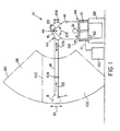
- a user grasping limb interface 8 can move limb interface 8 in the directions indicated by arrows D1, D2 and D3 in a spherical configuration anywhere within the three dimensional resistance field 90 to exercise a full functional motion.
- exercise apparatus 10 only has three degrees of freedom which are braked, the user can exercise a six degree of freedom motion.
- a user can exercise virtually any functional motion, for example, rowing, swimming, pitching, hitting a baseball or hitting a tennis ball, etc.
- Such specificity in training can increase an athlete's performance as well as help reduce injuries.
- the faster the user moves limb interface 8 within resistance field 90 the greater the resistance that is provided by exercise apparatus 10.
- the movement of the user's hand is resisted by exercise apparatus 10 in a direction directly opposite to such movement at any point along the path of movement. This guarantees force velocity colinearity resulting in a natural feeling cause and effect motion.
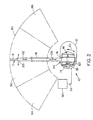
- Computer 110 can be programmed to provide resistance field 90 with separate areas of varying resistance. In this manner, the user can control the workspace providing resistance where it is desired. For example, in FIG. 1, dividing line 100 divides resistance field 90 into two resistance areas 98 and 102. Resistance area 98 provides a different amount of resistance than resistance area 102. Such an arrangement can be employed to simulate, for example, the waterline for exercising swimming or rowing motions. Referring to FIG. 2, resistance field 90 is divided into three different resistance areas 94, 92 and 96 as an example of another configuration of resistance areas. In other preferred embodiments, resistance areas can be employed to help guide a user through a desired motion, for example, a throwing motion. In such a case, one resistance area is shaped to have the path of the throwing motion and has less resistance than the surrounding resistance areas which thus helps passively guide the user along the desired motion. If desired, multiple resistance areas can be employed to simulate actual conditions.
- limb interface 8 includes an outer yoke 120 which is secured to the distal end of arm member 18.
- An intermediate yoke 122 is rotatably mounted to outer yoke 120 along an axis 121 by rotary joints 128a and 128b.
- An inner yoke 124 is rotatably mounted to intermediate yoke 122 along an axis 123 by rotary joint 130.
- Axis 123 is preferably orthogonal to axis 121.
- Gripping handle 126 is rotatably mounted to inner yoke 124 along an axis 125 by rotary joint 132.
- This configuration provides limb interface 8 with a gimbal joint 7 having three unbraked rotational degrees of freedom. The gimbal joint 7 allows the user's hand to be comfortably oriented at almost any position relative to exercise apparatus 10 during use.
- Arm member 18 is an elongate tubular member that is preferably about 4" in diameter and 80" long. Although arm member 18 preferably has a round cross section and is completely hollow, alternatively, arm member 18 can have other suitable cross sections such as polygonal or oval cross sections and can have internal structural supports.
- Sliding joint 44 includes two bearing members 65 which are mounted at opposite ends of shoulder member 16 and are preferably spaced apart about 11 inches.
- Each bearing member 65 includes four nylon rollers 64 about 1 1 ⁇ 4 inches in diameter and 9/16 inches wide. The rollers are rotatably positioned equidistantly from each other at the corners of bearing members 65 and engage the outer surface of arm member 18.
- Bearing members 65 enable sliding joint 44 to be a low friction sliding joint.
- a front stop 104 and a rear stop 106 are positioned on arm member 18 to allow about 40" of travel and prevents the arm member 18 from sliding out of sliding joint 44 by engaging against rollers 64.
- bearing members 65 have been shown to have four rollers 64, alternatively, bearing members 65 can have as little as three rollers or more than four rollers.
- rollers 64 can have a contoured surface to more securely engage the outer surface of arm member 18.
- the dimensions of rollers 64 can be varied and other suitable materials can be employed such as other plastics, rubber or metal.
- Shoulder member 16 includes two side plates 28a and 28b which are spaced apart from each other by bearing members 65, three tie rods 15 and a bottom plate (not shown) extending between the bottoms of bearing members 65.
- Shoulder member 16 is rotatably mounted to turret 14 along rotary shoulder joint 46 by two shafts 52a and 52b which extend from side plates 28a/28b.
- Shafts 52a/52b are supported within the side members 20a/20b of turret 14 by roller bearings 86.
- Side plates 28a/28b are each preferably made of two pieces, an upper and lower piece.
- side plates 28a/28b have outer rims 29a and 29b which extend in a semi-circle about rotary shoulder joint 46 to form a pulley which is preferably about 15 5/8 inches in diameter and 7/8 inches wide (FIG. 8).
- Transmission T3 includes a brake pulley 26 which is mounted to the brake shaft 50 of brake B3. Brake B3 is mounted to side plate 28b with brake shaft 50 extending to side plate 28a where it is rotatably supported by a bearing 51. Transmission T3 further includes two cables 27 which are preferably about 2.4 mm in diameter and have less than 5 mm of deflection for a load of 500 N. One cable 27 extends along arm member 18 from end stop 106 to brake pulley 26. The second cable 27 extends along arm member 18 from end plate 108 to brake pulley 26. The two cables 27 engage and wrap around brake pulley 26 in antagonistic directions (see FIG. 6) and are fixed thereon.
- Brake pulley 26 is preferably about 2 5/8 inches in diameter and is capable of converting longitudinal forces on arm member 18 of up to 500 N into torques on brake shaft 50 of up to 17 N-m.
- a wear band 27a is preferably provided underneath cables 27 along the travel portion of arm member 18 for dampening resonances and providing wear protection of arm member 18.
- Turret 14 includes side members 20a/20b which are mounted to a support plate 22. Side members 20a/20b are further strengthened by support brackets 24a and 24b respectively, which provide lateral support. Side members 20a/20b include open portions 76 and 78 (FIG. 8) which minimizes the weight of turret 14.
- Transmission T1 is a two stage torque reduction cable drive transmission located within turret 14 which couples rotary shoulder joint 46 to brake B1.
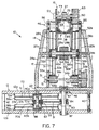
- Transmission T1 includes two turret pulleys 30a and 30b which are rotatably mounted to side members 20a/20b along a shaft 56 with ball bearings 86 (FIG. 7).
- Pulleys 30a/30b have outer rims 33a and 33b, respectively, as well as hubs 32a and 32b which extend inwardly towards each other.
- the hubs 32a/32b are connected to their respective outer rims 33a/33b by spokes 31 (FIG. 8).
- Pulleys 30a/30b are preferably about 15 1/4 inches in diameter and are about 2 inches wide.
- Hubs 32a/32b are preferably about 3 inches in diameter with the outer surfaces being grooved to ensure that cables will wind on them in an orderly fashion.
- Pulleys 30a/30b are spaced apart by a spacer 54.
- a rubber roller 62 is mounted to spacer 54 and serves as a pitch axis stop to prevent shoulder member 16 from over pivoting.
- Transmission T1 also includes brake pulleys 34a and 34b which are supported by a brake shaft 58 extending from brake B1.
- Brake pulleys 34a/34b are preferably about 2 1/4 inches in diameter by 3 inches long and have grooved outer surfaces for winding cable in an orderly fashion.
- Brake B1 is mounted to side member 20b and shaft 58 is supported at side member 20a by a roller bearing 51.
- Sensor S1 is mounted to side member 20a and is positioned at the end of brake shaft 58 for sensing the rotational displacement of brake shaft 58.
- cables 66a and 66b which preferably have diameters of 3.2 mm are fixed to opposing sides of the outer rims 29a/29b of side plates 28a/28b and wrap around a portion of the outer rims 29a/29b before engaging respective hubs 32a/32b of pulleys 30a/30b. Cables 66a/66b wrap around hubs 32a/32b in opposing directions and are fixed to the hubs 32a/32b. As a result, rotation of shoulder member 16 about rotary shoulder joint 46 in either direction causes the rotation of a pulley 30a or 30b.
- This first stage of transmission T1 preferably provides about a 5 to 1 torque reduction between outer rims 29a/29b and hubs 32a/32b.
- cables 68a and 68b which are preferably 2.4 mm in diameter are attached to the outer rims 33a/33b of pulleys 30a/30b. Cables 68a/68b wrap around the outer rims 33a/33b in opposing directions and engage respective brake pulleys 34a/34b. Cables 68a/68b wrap around brake pulleys 34a/34b in opposing directions and are fixed to the brake pulleys.
- This second stage of transmission T1 preferably provides about a 6.5 to 1 torque reduction with the total torque reduction of the two stages of transmission T1 preferably being about 32.5 to 1.
- FIG. 8 depicts the cabling scheme for cables 66a and 68a.
- Cable 66a wraps around the outer rim 29a of side member 28a and hub 32a in the opposite direction that cable 68a wraps around the outer rim 33a of pulley 30a and brake pulley 34a such that brake shaft 58 will rotate in the same direction that rotary shoulder joint 46 is rotated.
- the cabling scheme for cables 66b and 68b is the same but are in the opposite direction.
- rotary waist joint 48 rotatably couples turret 14 to base 12 and includes a shaft 60 extending downwardly from support plate 22.
- Shaft 60 is supported by bearings 87 which are housed in the upper plate 12a and lower plate 12b of base 12.
- Upper plate 12a and lower plate 12b are spaced apart from each other by a series of connecting rods 42 located along the perimeter of the upper and lower plates 12a/12b.
- Transmission T2 is a two stage torque reduction cable drive transmission located within base 12 which couples rotary waist joint 48 to brake B2.
- Transmission T2 includes a turret output pulley 36 which is fixed to shaft 60.
- Output pulley 36 has a semi-circular outer rim 35 which is connected to the inner hub by spokes 31.
- Outer rim 35 preferably has a diameter of about 15 5/8 inches and is about 1 5/8 inches wide.
- a horizontally positioned upper base pulley 38a and a horizontally position lower base pulley 38b are rotatably mounted to base 12 by a shaft 63 and four bearings 86.
- Pulleys 38a/38b are similar to and have the same dimensions as turret pulleys 30a/30b.
- Pulleys 38a/38b straddle output pulley 36 and have respective hubs 40a and 40b which extend inwardly towards each other.
- Brake B2 is mounted to the underside of lower plate 12b.
- Brake shaft 82 extends from brake B2 to upper plate 12a and where it is supported by bearing 51.
- Two brake pulleys 80a and 80b are mounted to brake shaft 82.
- Brake pulleys 80a/80b are similar to and have the same dimensions as brake pulleys 34a/34b.
- Sensor S2 is mounted to upper plate 12a and is positioned at the end of brake shaft 82 for sensing the rotational displacement of brake shaft 82.
- output pulley 36 has two cables 70a and 70b preferably having diameters of 3.2 mm which are fixed to opposite sides of the pulley and wrap about the outer rim 35 in opposing directions.
- Cable 70a engages hub 40a of upper base pulley 38a and cable 70b engages the hub 40b of lower base pulley 38b.
- Cables 70a/70b wrap around hubs 40a/40b in opposing directions and are fixed to hubs 40a/40b.
- cables 72a and 72b which are preferably 2.4 mm in diameter are fixed to the outer rims 37a and 37b of pulleys 38a/38b. Cables 72a/72b wrap about the outer rims 37a/37b in opposite directions and engage brake pulleys 80a/80b respectively. Cables 72a/72b wrap in opposite directions about brake pulleys 80a/80b and are fixed thereon.
- the torque ratio reduction for each stage of transmission T2 is preferably the same as in transmission T1 resulting in a total torque reduction of preferably about 32.5 to 1.
- FIG. 9 depicts the cabling scheme for cables 70b and 72b.
- Cable 70b wraps around the outer rim 35 of pulley 36 and hub 40b in the opposite direction that cable 72b wraps around the outer rim 37b of pulley 38b and brake pulley 80b such that brake shaft 82 will rotate in the same direction that rotary waist joint 48 is rotated.
- the cabling scheme for cables 70a and 72a are similar but are in the opposite direction.
- brake shaft 82 can be rotated in both rotational directions upon rotation of turret 14 about rotary waist joint 48.
- FIG. 10 depicts the cable support scheme for pulley 38b.
- Pulley 38b includes a guide wire 71 wrapped around and bonded to the outer rim 37b in a helix.
- the guide wire 71 supports the lower surface of cable 72b and prevents cable 72b from sliding off the pulley 38b.
- Pulleys 36 and 38a also include a guide wire 71 wrapped about the outer rims in a similar fashion for supporting and preventing cables 70a, 70b and 72a from slipping off.
- exercise apparatus 10 Most of the components of exercise apparatus 10 are preferably made of aluminum to minimize the inertia of the apparatus.
- FIG. 11 depicts a preferred method for controlling brakes B1, B2 and B3.
- brake B1 the control format for brakes B2 and B3 are similar.
- transmission T1 causes brake shaft 58 to rotate and the rotation of brake shaft 58 is sensed by sensor S1.
- a signal proportional to the rate of rotational displacement of brake shaft 58 is provided to computer 110.
- Computer 110 executes a processing step 114 to convert the rotational displacement into rotational velocity and then runs an algorithm step 116 to determine the signal necessary for controlling brake B1 for resisting that rotational velocity.
- This signal is sent to power amplifier 112 which amplifies the signal.
- the amplified signal is then sent to brake B1 which provides the appropriate resistance for the signal received.
- the faster brake shaft 58 turns the more resistance is provided by brake B1.
- FIG. 12 depicts another preferred limb interface 140.
- Limb interface 140 includes an outer yoke 142 which is mounted to arm member 18.
- An inner frame 144 is rotatably mounted to outer yoke 142 by joints 150a and 150b.
- a bearing 146 is mounted to inner frame 144 providing a rotary joint 152 which is orthogonal to rotary joints 150a and 150b.
- a handle 148 is rotatably mounted within bearing 146 along rotary joint 154.
- Limb interface 8 provides three unbraked rotational degrees of freedom.
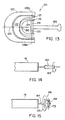
- FIG. 13 depicts another preferred limb interface 180.
- Limb interface differs from limb interface 8 in that a handle of a baseball bat 182 is fixed to handle 126 in order to allow exercising of a bat swinging motion.
- computer 110 can be programmed such that exercise apparatus 10 provides resistance in the forward swing only. The resistance can also be greatest at a position simulating the point of impact with a baseball.
- other types of handles can be fixed to handle 126 such as a hockey stick handle, golf club handle, tennis racket handle, etc.
- handles can be fixed to handle 148 of limb interface 140.
- FIGs. 14 and 15 depict other preferred limb interfaces.
- limb interface 160 includes a handle that is rotatable only about a single axis as indicated by arrow 162.
- a user grasping limb interface 160 can exercise, for example, a rowing motion.
- limb interface 164 provides two rotational degrees of freedom.
- Limb interface 164 includes a yoke 166 and a handle 168 each of which are rotatable about a separate axis as depicted by arrows 170 and 172.
- exercise apparatus 10 has been described for performing exercises, apparatus 10 can also be employed with interactive video games or virtual reality applications. In such uses, complex resistance areas can be programmed into computer 110 to make the experience seem realistic or more exciting.
- exercise apparatus 10 has been described to provide resistance that is proportional to the speed at which joints 44, 46 and 48 move, in other preferred embodiments, exercise apparatus 10 can be programmed to provide constant force resistance or resistance having a load profile which varies depending upon position, velocity or direction.
- a virtual object best described as a "sticky box with marshmallow filling" can be located within the work space. Outside the object, the user is free to move and find the outer surfaces of the object. Once the outer surface is found, the user sticks to the outer surface but with effort, can either pull away from the outer surface or push through the viscous center where the resisting force is proportional to the speed.
- the joints of the limb interfaces are preferably unbraked, selected joints of the limb interfaces can be braked.
- the limb interfaces can also be attached to the legs, elbows, head and torso of the user. In such cases, appropriate modifications to the limb interface are required.
- exercise apparatus 10 is shown to be positioned on a floor stand, alternatively, the present invention exercise apparatus can be suspended upside down or positioned sideways.
Landscapes
- Health & Medical Sciences (AREA)
- Orthopedic Medicine & Surgery (AREA)
- General Health & Medical Sciences (AREA)
- Physical Education & Sports Medicine (AREA)
- Life Sciences & Earth Sciences (AREA)
- Biophysics (AREA)
- Rehabilitation Therapy (AREA)
- Pain & Pain Management (AREA)
- Epidemiology (AREA)
- Animal Behavior & Ethology (AREA)
- Public Health (AREA)
- Veterinary Medicine (AREA)
- Rehabilitation Tools (AREA)
- Supplying Of Containers To The Packaging Station (AREA)
- Eye Examination Apparatus (AREA)
- Percussion Or Vibration Massage (AREA)
Abstract
Description
Claims (10)
- A passive exercise apparatus comprising:an interface member (8) for coupling to a user's body;an arm member (18) coupled to the interface member by a wrist joint (7), the wrist joint (7) having rotational motion about three axes;a first link (16) coupled to the arm member (18) by a sliding joint (44), the sliding joint (44) allowing translational motion of the arm member (18) relative to the first link (16);a second link (14) rotatably coupled to the first link (16) by a first rotary joint (46);a third link (12) rotatably coupled to the second link (14) by a second rotary joint (48);a first rotary brake (B1) coupled to the first rotary joint (46) for resisting movement of the first rotary joint (46);a second rotary brake (B2) coupled to the second rotary joint (48) for resisting movement of the second rotary joint (48); anda third rotary brake (B3) coupled to the arm member (18) for resisting movement of the arm member (18), wherein the user is capable of interfacing with the apparatus to exercise a six degree of freedom motion.
- The apparatus of Claim 1 in which the wrist joint (7) is unbraked.
- The apparatus of Claim 1 further comprising first, second and third transmissions (T1,T2,T3) which are coupled between the first, second and third brakes (B1,B2,B3) and the first joint (46), the second joint (48) and the arm member (18) respectively, for reducing torque to the brakes.
- The apparatus of Claim 3 in which the ratio of the first transmission (TI) is about 30:1 or greater, and, optionally in which the first transmission comprises a two-stage cable drive.
- The apparatus of Claim 3 in which the ratio of the second transmission (T2) is about 30:1 or greater, and, optiernally, in which the second transmission comprises a two-stage cable drive, and, further optionally, in which the second transmission (T2) includes at least one horizontally oriented pulley for engaging a cable, said pulley having a wire encircling the pulley for vertically supporting said cable to prevent said cable from slipping off said pulley.
- The apparatus of Claim 3 in which the third transmission (T3) coupled between the arm member (18) and the third brake (B3) comprises:a cable (27) secured to the arm member (18); anda pulley (26) rotatably coupled to the third brake (B3), said cable (27) rotatably engaging the pulley (26).
- The apparatus of Claim 1 further comprising first, second and third sensors (S1,S2,S3) for sensing movement of the first rotary joint (46), second rotary joint (48) and the arm member (18) respectively, the amount of resistance provided by the first, second and third brakes (B1,B2,B3) being proportional to the movement sensed by the sensors (S1,S2,S3).
- The apparatus of Claim 1 further comprising a three dimensional resistance field in which the user moves the interface member while exercising, and, optionally,
in which the resistance field has first and second resistance areas, wherein the level of resistance provided by the first area differs from the level of resistance provided by the second area, and, further optionally,
in which the first and second resistance areas each have a shape that can be varied. - A method of exercising comprising the steps of:coupling an interface member (8) of an exercise apparatus to a user's body, the interface member (8) being coupled to an arm member (18) by a wrist joint (7), the wrist joint (7) providing rotational motion about three axes, the arm member (8) being coupled to a first link (16) by a sliding joint (44), the sliding joint (44) allowing translational motion of the arm member (18) relative to the first link (16), a second link (14) being rotatably coupled to the first link (16) by a first rotary joint (46) and a third link (12) being rotatably coupled to the second link (14) by a second rotary joint (48);moving the limb in a desired motion relative to the exercise apparatus;resisting movement of the first rotary joint (46) with a first rotary brake (B1) coupled to the first rotary joint (46);resisting movement of the second rotary joint (48) with a second rotary brake (B2) coupled to the second rotary joint (48); andresisting movement of the arm member (18) with a third rotary brake (B3) coupled to the arm member (18), wherein the user is capable of interfacing with the apparatus to exercise a six degree of freedom motion.
- The method of Claim 9 further comprising either:a) the step of coupling the first rotary joint (46), the second rotary joint (48), and the arm member (18) to the first, second and third brakes (B1,B2,B3) with a first transmission, a second transmission and a third transmission (T1,T2,T3) respectively, said transmissions reducing the amount of torque to said brakes;b) the steps of:sensing movement of the first rotary joint (46), second rotary joint (48) and arm member (18) with first, second and third sensors (51,52,53), respectively; andcontrolling the amount of resistance provided by the first, second and third brakes (B1,B2,B3), the amount of resistance provided by each brake being proportional to the movement sensed by the sensors; orc) the step of providing a three dimensional resistance field in which the user moves the interface member while exercising, and, optionally, further comprising the steps of:providing a first resistance area within the resistance field; andproviding a second resistance area within the resistance field, the level of resistance provided by the first resistance area differing from the level of resistance provided by the second resistance area, and, yet further optionally, further comprising the step of shaping the first and second resistance areas.
Applications Claiming Priority (3)
| Application Number | Priority Date | Filing Date | Title |
|---|---|---|---|
| US780650 | 1997-01-09 | ||
| US08/780,650 US5755645A (en) | 1997-01-09 | 1997-01-09 | Exercise apparatus |
| PCT/US1998/000307 WO1998030287A1 (en) | 1997-01-09 | 1998-01-08 | Exercise apparatus |
Publications (2)
| Publication Number | Publication Date |
|---|---|
| EP0954354A1 EP0954354A1 (en) | 1999-11-10 |
| EP0954354B1 true EP0954354B1 (en) | 2003-05-14 |
Family
ID=25120232
Family Applications (1)
| Application Number | Title | Priority Date | Filing Date |
|---|---|---|---|
| EP98902425A Expired - Lifetime EP0954354B1 (en) | 1997-01-09 | 1998-01-08 | Exercise apparatus |
Country Status (6)
| Country | Link |
|---|---|
| US (1) | US5755645A (en) |
| EP (1) | EP0954354B1 (en) |
| AT (1) | ATE240135T1 (en) |
| AU (1) | AU5909598A (en) |
| DE (1) | DE69814588T2 (en) |
| WO (1) | WO1998030287A1 (en) |
Families Citing this family (101)
| Publication number | Priority date | Publication date | Assignee | Title |
|---|---|---|---|---|
| US7083554B1 (en) | 1997-02-27 | 2006-08-01 | Nautilus, Inc. | Exercise machine with infinite position range limiter and automatic belt tensioning system |
| US6183398B1 (en) | 1998-07-23 | 2001-02-06 | Unisen, Inc. | Exercise trainer with a stride multiplier |
| US7025710B2 (en) * | 1998-07-23 | 2006-04-11 | Unisen, Inc. | Elliptical exercise device and arm linkage |
| US6908416B2 (en) | 1998-07-23 | 2005-06-21 | Unisen, Inc. | Exercise and therapeutic trainer |
| WO2001014018A1 (en) * | 1999-08-20 | 2001-03-01 | The Regents Of The University Of California | Method, apparatus and system for automation of body weight support training (bwst) of biped locomotion over a treadmill using a programmable stepper device (psd) operating like an exoskeleton drive system from a fixed base |
| GB2369582B (en) * | 1999-09-01 | 2004-01-21 | Sumitomo Rubber Ind | Ball-batting implement testing device |
| US6517468B1 (en) * | 2000-02-28 | 2003-02-11 | Thomas G. Lapcevic | Exercise device |
| CA2402130C (en) * | 2000-03-06 | 2009-05-12 | Scott Sechrest | Functional trainer |
| US7922635B2 (en) | 2000-03-10 | 2011-04-12 | Nautilus, Inc. | Adjustable-load unitary multi-position bench exercise unit |
| US7108641B2 (en) | 2000-05-03 | 2006-09-19 | Nautilus, Inc. | Exercise equipment with multi-positioning handles |
| US20020052268A1 (en) * | 2000-05-03 | 2002-05-02 | Vicente Morcillo-Quintero | Exercise machine providing for natural movement |
| US7699754B2 (en) * | 2001-05-24 | 2010-04-20 | Kenneth George Schneider | Complete body fitness machine |
| US20040058784A1 (en) * | 2001-07-11 | 2004-03-25 | Roberts Robert E. | Stationary type of exercise apparatus that enables movement of the user's feet in a reciprocating motion |
| US7464630B2 (en) * | 2001-08-27 | 2008-12-16 | Flow International Corporation | Apparatus for generating and manipulating a high-pressure fluid jet |
| US20040077463A1 (en) * | 2002-02-26 | 2004-04-22 | Rodgers Robert E. | Stationary exercise apparatus with pivoting foot platforms |
| US7070545B2 (en) | 2002-07-01 | 2006-07-04 | Nautilus, Inc. | Leg press and abdominal crunch exercise machine |
| US7115080B2 (en) | 2002-08-01 | 2006-10-03 | Nautilus, Inc. | Collapsible seat for combination hack squat and leg press machine |
| US7223213B2 (en) * | 2002-08-08 | 2007-05-29 | Nautilus, Inc. | Dual-direction pulley system |
| US7169089B2 (en) * | 2003-06-06 | 2007-01-30 | Rodgers Jr Robert E | Compact variable path exercise apparatus with a relatively long cam surface |
| US7169088B2 (en) | 2003-06-06 | 2007-01-30 | Rodgers Jr Robert E | Compact variable path exercise apparatus |
| US7214168B2 (en) | 2003-06-06 | 2007-05-08 | Rodgers Jr Robert E | Variable path exercise apparatus |
| US7172531B2 (en) | 2003-06-06 | 2007-02-06 | Rodgers Jr Robert E | Variable stride exercise apparatus |
| US7244217B2 (en) | 2003-06-06 | 2007-07-17 | Rodgers Jr Robert E | Exercise apparatus that allows user varied stride length |
| US7201705B2 (en) | 2003-06-06 | 2007-04-10 | Rodgers Jr Robert E | Exercise apparatus with a variable stride system |
| US7201712B2 (en) * | 2003-07-14 | 2007-04-10 | Leif Tiahrt | Oscillatory resistance exercise device and method |
| US7695414B2 (en) * | 2003-07-14 | 2010-04-13 | Tiahrt Leif K | Varying force vector exercise device for inducing musculature perturbations |
| FR2860439A1 (en) * | 2003-10-02 | 2005-04-08 | Soderel Medical Sarl | Limb muscles and/or joints exercising apparatus for human body, has handle permitting user to rotate ball and socket joint around two axes by exerting force, and computer connected to electronic board to display parameters on screen |
| US20060293617A1 (en) * | 2004-02-05 | 2006-12-28 | Reability Inc. | Methods and apparatuses for rehabilitation and training |
| KR20070061476A (en) * | 2004-02-05 | 2007-06-13 | 모토리카 리미티드 | Neuromuscular stimulation |
| KR20070054596A (en) * | 2004-02-05 | 2007-05-29 | 모토리카 리미티드 | Rehabilitation Methods and Devices and Training Applications |
| US8112155B2 (en) * | 2004-02-05 | 2012-02-07 | Motorika Limited | Neuromuscular stimulation |
| US8888723B2 (en) * | 2004-02-05 | 2014-11-18 | Motorika Limited | Gait rehabilitation methods and apparatuses |
| KR20070054595A (en) * | 2004-02-05 | 2007-05-29 | 모토리카 리미티드 | Methods and apparatus for rehabilitation exercises and training |
| GB0403936D0 (en) * | 2004-02-21 | 2004-03-24 | Mason James R | Fitness apparatus |
| US8938289B2 (en) * | 2004-08-25 | 2015-01-20 | Motorika Limited | Motor training with brain plasticity |
| EP1850824B1 (en) * | 2005-02-04 | 2016-07-13 | Motorika Limited | Methods and apparatuses for rehabilitation and training |
| EP1690569A1 (en) * | 2005-02-12 | 2006-08-16 | Leao Wang | Extendable swing arm assembly for a treadmill |
| RU2293584C1 (en) * | 2005-05-11 | 2007-02-20 | Евгений Петрович Коваль | General-purpose sportive exerciser (versions) |
| US7507215B2 (en) | 2005-07-08 | 2009-03-24 | Jri Development Group, Llc | Orthotic brace |
| CA2650794C (en) | 2006-05-11 | 2014-05-13 | Rehabtronics Inc. | Method and apparatus for automated delivery of therapeutic exercises of the upper extremity |
| US20080026920A1 (en) * | 2006-07-27 | 2008-01-31 | Annaniy Berenshteyn | Weightlifting apparatus for pronation and supination exercises |
| BE1017398A3 (en) * | 2006-12-15 | 2008-08-05 | Arys Yves | Body movement measuring device for muscle exercise and rehabilitation apparatus, includes servo motor for applying controlled load to rotation axes for moving part |
| US8540652B2 (en) * | 2007-05-22 | 2013-09-24 | The Hong Kong Polytechnic University | Robotic training system with multi-orientation module |
| US7854708B2 (en) * | 2007-05-22 | 2010-12-21 | Kai Yu Tong | Multiple joint linkage device |
| WO2010040416A1 (en) * | 2008-10-10 | 2010-04-15 | Fundacion Fatronik | Universal haptic drive system |
| US20100111645A1 (en) * | 2008-11-04 | 2010-05-06 | Mayez Al-Mouhamed | Anthropomorphic force-reflective master arm |
| US8770905B2 (en) * | 2008-11-04 | 2014-07-08 | King Fahd University Of Petroleum And Minerals | Anthropomorphic force-reflective master arm |
| US8574178B2 (en) | 2009-05-26 | 2013-11-05 | The Hong Kong Polytechnic University | Wearable power assistive device for helping a user to move their hand |
| TW201127450A (en) * | 2010-02-12 | 2011-08-16 | B Green Technology Co Ltd | Athletic equipment capable of assorting operations for providing controllable speed power |
| US9339691B2 (en) | 2012-01-05 | 2016-05-17 | Icon Health & Fitness, Inc. | System and method for controlling an exercise device |
| CN102631277B (en) * | 2012-03-31 | 2013-12-18 | 中国科学院宁波材料技术与工程研究所 | Rocker type upper limb rehabilitation device and method for performing rehabilitation training by aid of rocker type upper limb rehabilitation device |
| CN104884133B (en) | 2013-03-14 | 2018-02-23 | 艾肯运动与健康公司 | Force exercise equipment with flywheel |
| EP3974036B1 (en) | 2013-12-26 | 2024-06-19 | iFIT Inc. | Magnetic resistance mechanism in a cable machine |
| WO2015138339A1 (en) | 2014-03-10 | 2015-09-17 | Icon Health & Fitness, Inc. | Pressure sensor to quantify work |
| WO2015191445A1 (en) | 2014-06-09 | 2015-12-17 | Icon Health & Fitness, Inc. | Cable system incorporated into a treadmill |
| WO2015195965A1 (en) | 2014-06-20 | 2015-12-23 | Icon Health & Fitness, Inc. | Post workout massage device |
| KR101555871B1 (en) * | 2014-07-07 | 2015-09-30 | 재단법인대구경북과학기술원 | Upper limb rehabilitation robot |
| WO2016020457A1 (en) * | 2014-08-08 | 2016-02-11 | Ecole polytechnique fédérale de Lausanne (EPFL) | Upper limb rehabilitation system |
| JP6341057B2 (en) * | 2014-10-29 | 2018-06-13 | 村田機械株式会社 | Training equipment |
| US10258828B2 (en) | 2015-01-16 | 2019-04-16 | Icon Health & Fitness, Inc. | Controls for an exercise device |
| US20180289577A1 (en) * | 2015-01-18 | 2018-10-11 | Calabrian High Tech Srl | Six Degrees of Freedom Self Balanced Hybrid Serial-Parallel Robotic Systemfor Rehabilitation of Upper and Lower Limbs, Left and Right |
| US10391361B2 (en) | 2015-02-27 | 2019-08-27 | Icon Health & Fitness, Inc. | Simulating real-world terrain on an exercise device |
| US10953305B2 (en) | 2015-08-26 | 2021-03-23 | Icon Health & Fitness, Inc. | Strength exercise mechanisms |
| US10940360B2 (en) | 2015-08-26 | 2021-03-09 | Icon Health & Fitness, Inc. | Strength exercise mechanisms |
| TWI644702B (en) | 2015-08-26 | 2018-12-21 | 美商愛康運動與健康公司 | Strength exercise mechanisms |
| CN105148455B (en) * | 2015-10-22 | 2018-02-16 | 山东中医药大学附属医院 | Hemiplegia device for rehabilitation |
| US10493349B2 (en) | 2016-03-18 | 2019-12-03 | Icon Health & Fitness, Inc. | Display on exercise device |
| US10441840B2 (en) | 2016-03-18 | 2019-10-15 | Icon Health & Fitness, Inc. | Collapsible strength exercise machine |
| US10272317B2 (en) | 2016-03-18 | 2019-04-30 | Icon Health & Fitness, Inc. | Lighted pace feature in a treadmill |
| US10561894B2 (en) | 2016-03-18 | 2020-02-18 | Icon Health & Fitness, Inc. | Treadmill with removable supports |
| US10293211B2 (en) | 2016-03-18 | 2019-05-21 | Icon Health & Fitness, Inc. | Coordinated weight selection |
| US10625137B2 (en) | 2016-03-18 | 2020-04-21 | Icon Health & Fitness, Inc. | Coordinated displays in an exercise device |
| US10252109B2 (en) | 2016-05-13 | 2019-04-09 | Icon Health & Fitness, Inc. | Weight platform treadmill |
| US9861856B1 (en) | 2016-06-21 | 2018-01-09 | Boston Biomotion, Inc. | Computerized exercise apparatus |
| US10471299B2 (en) | 2016-07-01 | 2019-11-12 | Icon Health & Fitness, Inc. | Systems and methods for cooling internal exercise equipment components |
| US10441844B2 (en) | 2016-07-01 | 2019-10-15 | Icon Health & Fitness, Inc. | Cooling systems and methods for exercise equipment |
| US9823686B1 (en) * | 2016-08-15 | 2017-11-21 | Clause Technology | Three-axis motion joystick |
| US9889874B1 (en) * | 2016-08-15 | 2018-02-13 | Clause Technology | Three-axis motion joystick |
| US10671705B2 (en) | 2016-09-28 | 2020-06-02 | Icon Health & Fitness, Inc. | Customizing recipe recommendations |
| US10500473B2 (en) | 2016-10-10 | 2019-12-10 | Icon Health & Fitness, Inc. | Console positioning |
| US10376736B2 (en) | 2016-10-12 | 2019-08-13 | Icon Health & Fitness, Inc. | Cooling an exercise device during a dive motor runway condition |
| TWI646997B (en) | 2016-11-01 | 2019-01-11 | 美商愛康運動與健康公司 | Distance sensor for console positioning |
| US10661114B2 (en) | 2016-11-01 | 2020-05-26 | Icon Health & Fitness, Inc. | Body weight lift mechanism on treadmill |
| TWI680782B (en) | 2016-12-05 | 2020-01-01 | 美商愛康運動與健康公司 | Offsetting treadmill deck weight during operation |
| RU2655450C1 (en) * | 2017-02-14 | 2018-05-28 | Федеральное государственное бюджетное образовательное учреждение высшего образования "ОРЛОВСКИЙ ГОСУДАРСТВЕННЫЙ УНИВЕРСИТЕТ имени И.С. ТУРГЕНЕВА" (ОГУ им. И.С. Тургенева) | Non-contact finger seal with active gap control |
| US9827461B1 (en) * | 2017-03-27 | 2017-11-28 | Larry D. Miller Trust | Elliptical exercise device |
| US11451108B2 (en) | 2017-08-16 | 2022-09-20 | Ifit Inc. | Systems and methods for axial impact resistance in electric motors |
| US10888732B2 (en) | 2017-11-01 | 2021-01-12 | Proteus Motion Inc. | Exercise device limb interface |
| AT520763B1 (en) * | 2017-12-21 | 2022-09-15 | Hans Kuenz Gmbh | crane control |
| US10729965B2 (en) | 2017-12-22 | 2020-08-04 | Icon Health & Fitness, Inc. | Audible belt guide in a treadmill |
| CN107998617A (en) * | 2017-12-29 | 2018-05-08 | 力迈德医疗(广州)有限公司 | Multi-dimension arm image training robot |
| US12121768B2 (en) * | 2020-03-19 | 2024-10-22 | Proteus Motion Inc. | Exercise device having a linear arm portion |
| US11529543B2 (en) * | 2020-03-19 | 2022-12-20 | Proteus Motion Inc. | Exercise device having a linear arm portion |
| US11607586B1 (en) | 2020-08-03 | 2023-03-21 | Titin Km Biomedical Corp. | Shoulder strengthening apparatus |
| WO2022104312A1 (en) | 2020-11-12 | 2022-05-19 | Proteus Motion Inc. | Exercise handle |
| US12611570B2 (en) | 2020-11-29 | 2026-04-28 | Eun Bee Kim | Exercise method and device |
| US20220288447A1 (en) * | 2021-03-10 | 2022-09-15 | Kenneth Spurgin | Rotational exercise machine |
| WO2023080978A1 (en) * | 2021-11-08 | 2023-05-11 | Titin Km Biomedical Corp. | Shoulder strengthening systems |
| US20240050801A1 (en) * | 2021-11-18 | 2024-02-15 | Rom Technologies, Inc. | System, method and apparatus for rehabilitation and exercise |
| EP4732915A1 (en) * | 2024-10-23 | 2026-04-29 | Free Bionics Taiwan Inc. | Training device and utilizing method thereof |
| CN119792882B (en) * | 2024-12-16 | 2026-02-13 | 浙江理工大学 | A multidimensional exercise trainer for the upper limbs |
Family Cites Families (47)
| Publication number | Priority date | Publication date | Assignee | Title |
|---|---|---|---|---|
| US2139166A (en) * | 1935-08-01 | 1938-12-06 | Rodolphe Lallemand | Universal mechano-surgical apparatus |
| GB1051818A (en) * | 1965-09-14 | 1900-01-01 | ||
| US4235437A (en) * | 1978-07-03 | 1980-11-25 | Book Wayne J | Robotic exercise machine and method |
| US4354676A (en) * | 1978-10-13 | 1982-10-19 | Pepsico, Inc. | Exerciser |
| US4544154A (en) * | 1978-10-13 | 1985-10-01 | Pepsico, Inc. | Passive programmable resistance device |
| US4263915A (en) * | 1978-11-06 | 1981-04-28 | Medtronic, Inc. | Digital cardiac pacemaker with hysteresis |
| US4261562A (en) * | 1978-12-22 | 1981-04-14 | Flavell Evan R | Electromagnetically regulated exerciser |
| US4258913A (en) * | 1979-04-09 | 1981-03-31 | Brentham Jerry D | Forearm exerciser |
| US4478412A (en) * | 1982-05-26 | 1984-10-23 | Muir Arthur M | Exercise device and control valve therefor |
| FR2541574B3 (en) * | 1983-02-24 | 1985-12-13 | Seram | ASSISTANCE APPARATUS SUPPORTING AND BALANCING A RIGHT OR LEFT MEMBER IN ALL POSITIONS |
| US4577862A (en) * | 1984-01-30 | 1986-03-25 | Sagedahl Steven M | Isokinetic exercise apparatus and method |
| US4592545A (en) * | 1984-01-30 | 1986-06-03 | Sagedahl Steven M | Isokinetic exercise apparatus and method |
| US4620703A (en) * | 1984-10-12 | 1986-11-04 | Greenhut Paul M | Exercise apparatus |
| US4629185A (en) * | 1985-07-11 | 1986-12-16 | Amann Michael J | Universal hydraulic exerciser |
| US4628185A (en) * | 1985-08-05 | 1986-12-09 | Black & Decker, Inc. | Toaster oven and protective hood |
| GB8621160D0 (en) * | 1986-09-02 | 1986-10-08 | Cooke & Sons Engineers Est 192 | Training apparatus |
| FR2604911B1 (en) * | 1986-10-13 | 1989-06-02 | Merobel | TRAINING, INVESTIGATION AND REHABILITATION APPARATUS, ESPECIALLY OF THE NEURO-MUSCULAR FUNCTION |
| US4772015A (en) * | 1987-04-23 | 1988-09-20 | The Toro Company | Shoulder and arm exercise machine |
| US4872668A (en) * | 1987-09-16 | 1989-10-10 | Joseph Patrick Mcgillis | Multidirectional exerciser |
| FR2624002B1 (en) * | 1987-12-03 | 1991-01-18 | Monge Lycee Tech | BALANCED ORTHESIS, MODULAR, ADJUSTABLE, ADAPTABLE ON ALL MEDIA AND MOTORALLY TOTALLY OR PARTIALLY, FOR THE FUNCTIONAL ASSISTANCE OF A MEMBER |
| US5410472A (en) * | 1989-03-06 | 1995-04-25 | Ergometrx Corporation | Method for conditioning or rehabilitating using a prescribed exercise program |
| US5039089A (en) * | 1990-01-12 | 1991-08-13 | Lapcevic Thomas G | Exercise device having a variable resistance curve |
| US5244441A (en) * | 1990-01-31 | 1993-09-14 | Loredan Biomedical, Inc. | Position-based motion controller |
| US5052375A (en) * | 1990-02-21 | 1991-10-01 | John G. Stark | Instrumented orthopedic restraining device and method of use |
| US5231998A (en) * | 1990-06-25 | 1993-08-03 | Massachusetts Institute Of Technology | Whole-arm orthosis for steadying limb motion |
| US5042799A (en) * | 1990-10-09 | 1991-08-27 | Stanley Ronald F | Portable arm and leg exercise device utilizing a friction force resister |
| US5242344A (en) * | 1990-10-31 | 1993-09-07 | Hundley Kenneth W | Limb movement exercising and training apparatus |
| US5193963A (en) * | 1990-10-31 | 1993-03-16 | The United States Of America As Represented By The Administrator Of The National Aeronautics And Space Administration | Force reflecting hand controller |
| GB2249733B (en) * | 1990-11-13 | 1994-11-23 | Vincent Frank Basile | A bicep exercise machine |
| US5163451A (en) * | 1990-12-19 | 1992-11-17 | Sutter Corporation | Rehabilitation patient positioning method |
| US5201772A (en) * | 1991-01-31 | 1993-04-13 | Maxwell Scott M | System for resisting limb movement |
| US5072932A (en) * | 1991-02-26 | 1991-12-17 | Johnson John B | Exercise apparatus |
| US5362298A (en) * | 1991-03-13 | 1994-11-08 | Motivator, Inc. | User force application device for an exercise, physical therapy, or rehabilitation apparatus |
| US5254066A (en) * | 1991-03-13 | 1993-10-19 | Motivator, Inc. | User force application device for an exercise, physical therapy, or rehabilitation apparatus |
| JPH0796039B2 (en) * | 1991-05-22 | 1995-10-18 | 英夫 高岡 | Training equipment structure |
| US5324247A (en) * | 1991-11-26 | 1994-06-28 | Alaska Research And Development, Inc. | Apparatus and method for multi-axial spinal testing and rehabilitation |
| US5314390A (en) * | 1992-01-31 | 1994-05-24 | Loredan Biomedical, Inc. | Linear tracking programmable exerciser |
| US5263382A (en) * | 1992-04-13 | 1993-11-23 | Hughes Aircraft Company | Six Degrees of freedom motion device |
| FR2691093B1 (en) * | 1992-05-12 | 1996-06-14 | Univ Joseph Fourier | ROBOT FOR GUIDANCE OF GESTURES AND CONTROL METHOD. |
| US5284464A (en) * | 1992-06-30 | 1994-02-08 | Lee Iii George P | Swing training and exercising apparatus |
| US5250016A (en) * | 1992-07-30 | 1993-10-05 | Higgins David W | Baseball throwing device for muscle development, rehabilitation and training |
| US5277681A (en) * | 1992-08-05 | 1994-01-11 | Parrsboro Metal Fabricators Limited | Stretching exercise machine |
| US5466213A (en) * | 1993-07-06 | 1995-11-14 | Massachusetts Institute Of Technology | Interactive robotic therapist |
| US5393280A (en) * | 1993-07-21 | 1995-02-28 | Haviv; Joseph | Swimming exercise and training apparatus |
| US5476441A (en) * | 1993-09-30 | 1995-12-19 | Massachusetts Institute Of Technology | Controlled-brake orthosis |
| US5354251A (en) * | 1993-11-01 | 1994-10-11 | Sleamaker Robert H | Multifunction excercise machine with ergometric input-responsive resistance |
| US5409435A (en) * | 1993-11-03 | 1995-04-25 | Daniels; John J. | Variable resistance exercise device |
-
1997
- 1997-01-09 US US08/780,650 patent/US5755645A/en not_active Expired - Lifetime
-
1998
- 1998-01-08 AU AU59095/98A patent/AU5909598A/en not_active Abandoned
- 1998-01-08 AT AT98902425T patent/ATE240135T1/en not_active IP Right Cessation
- 1998-01-08 EP EP98902425A patent/EP0954354B1/en not_active Expired - Lifetime
- 1998-01-08 WO PCT/US1998/000307 patent/WO1998030287A1/en not_active Ceased
- 1998-01-08 DE DE69814588T patent/DE69814588T2/en not_active Expired - Fee Related
Also Published As
| Publication number | Publication date |
|---|---|
| ATE240135T1 (en) | 2003-05-15 |
| DE69814588T2 (en) | 2004-04-01 |
| EP0954354A1 (en) | 1999-11-10 |
| AU5909598A (en) | 1998-08-03 |
| WO1998030287A1 (en) | 1998-07-16 |
| US5755645A (en) | 1998-05-26 |
| DE69814588D1 (en) | 2003-06-18 |
Similar Documents
| Publication | Publication Date | Title |
|---|---|---|
| US5755645A (en) | Exercise apparatus | |
| US5192257A (en) | Exercise apparatus | |
| US4592545A (en) | Isokinetic exercise apparatus and method | |
| US6080091A (en) | Exercise machine press arm | |
| US7806780B1 (en) | Robotic golf swing trainer | |
| US6220990B1 (en) | Jumping jack exercise machine | |
| US5554089A (en) | Military press exercise machine | |
| US5050871A (en) | Energy absorbing exercising and training machine | |
| EP1493467B1 (en) | An exercise machine | |
| US11969637B2 (en) | Spherical cage pitch training device with spinning ball | |
| US4577862A (en) | Isokinetic exercise apparatus and method | |
| CA1301795C (en) | Resistance training device | |
| US7867152B1 (en) | Multi-axis, multi-planar multi-exercise collapsible exercise device | |
| US5707323A (en) | Method and apparatus for exercising the rear deltoid muscle | |
| US20060030465A1 (en) | Reconfigurable attachment for rehabilitation equipment | |
| US6283898B1 (en) | Mechanical weightlifting machine | |
| US20050239614A1 (en) | Centrifugal force exercise apparatus and method | |
| JP3503117B2 (en) | Electromagnetic resistance load type trunk strength training machine | |
| EP0411892B1 (en) | Energy absorbing exercising and training machine | |
| EP0346363B1 (en) | A resistance training device | |
| CN223416665U (en) | A physical training device with adjustable training intensity | |
| US20230414990A1 (en) | Exercise Device And Exercise System | |
| CN222467978U (en) | Wrist exerciser | |
| US20250288853A1 (en) | Exercise machine | |
| CA1260032A (en) | Isokinetic exercise apparatus and method |
Legal Events
| Date | Code | Title | Description |
|---|---|---|---|
| PUAI | Public reference made under article 153(3) epc to a published international application that has entered the european phase |
Free format text: ORIGINAL CODE: 0009012 |
|
| 17P | Request for examination filed |
Effective date: 19990728 |
|
| AK | Designated contracting states |
Kind code of ref document: A1 Designated state(s): AT BE CH DE DK ES FI FR GB GR IE IT LI LU MC NL PT SE |
|
| RIN1 | Information on inventor provided before grant (corrected) |
Inventor name: LAROCQUE, BRANDON, D. Inventor name: MATSUOKA, YOKY Inventor name: YOERGER, DANA Inventor name: TOWNSEND, WILLIAM, T. Inventor name: ULRICH, NATHAN Inventor name: MILLER, LARRY, C. |
|
| 17Q | First examination report despatched |
Effective date: 20011218 |
|
| GRAH | Despatch of communication of intention to grant a patent |
Free format text: ORIGINAL CODE: EPIDOS IGRA |
|
| GRAH | Despatch of communication of intention to grant a patent |
Free format text: ORIGINAL CODE: EPIDOS IGRA |
|
| GRAA | (expected) grant |
Free format text: ORIGINAL CODE: 0009210 |
|
| AK | Designated contracting states |
Designated state(s): AT BE CH DE DK ES FI FR GB GR IE IT LI LU MC NL PT SE |
|
| PG25 | Lapsed in a contracting state [announced via postgrant information from national office to epo] |
Ref country code: NL Free format text: LAPSE BECAUSE OF FAILURE TO SUBMIT A TRANSLATION OF THE DESCRIPTION OR TO PAY THE FEE WITHIN THE PRESCRIBED TIME-LIMIT Effective date: 20030514 Ref country code: LI Free format text: LAPSE BECAUSE OF FAILURE TO SUBMIT A TRANSLATION OF THE DESCRIPTION OR TO PAY THE FEE WITHIN THE PRESCRIBED TIME-LIMIT Effective date: 20030514 Ref country code: IT Free format text: LAPSE BECAUSE OF FAILURE TO SUBMIT A TRANSLATION OF THE DESCRIPTION OR TO PAY THE FEE WITHIN THE PRESCRIBED TIME-LIMIT;WARNING: LAPSES OF ITALIAN PATENTS WITH EFFECTIVE DATE BEFORE 2007 MAY HAVE OCCURRED AT ANY TIME BEFORE 2007. THE CORRECT EFFECTIVE DATE MAY BE DIFFERENT FROM THE ONE RECORDED. Effective date: 20030514 Ref country code: FI Free format text: LAPSE BECAUSE OF FAILURE TO SUBMIT A TRANSLATION OF THE DESCRIPTION OR TO PAY THE FEE WITHIN THE PRESCRIBED TIME-LIMIT Effective date: 20030514 Ref country code: CH Free format text: LAPSE BECAUSE OF FAILURE TO SUBMIT A TRANSLATION OF THE DESCRIPTION OR TO PAY THE FEE WITHIN THE PRESCRIBED TIME-LIMIT Effective date: 20030514 Ref country code: BE Free format text: LAPSE BECAUSE OF FAILURE TO SUBMIT A TRANSLATION OF THE DESCRIPTION OR TO PAY THE FEE WITHIN THE PRESCRIBED TIME-LIMIT Effective date: 20030514 Ref country code: AT Free format text: LAPSE BECAUSE OF FAILURE TO SUBMIT A TRANSLATION OF THE DESCRIPTION OR TO PAY THE FEE WITHIN THE PRESCRIBED TIME-LIMIT Effective date: 20030514 |
|
| REG | Reference to a national code |
Ref country code: GB Ref legal event code: FG4D |
|
| REG | Reference to a national code |
Ref country code: CH Ref legal event code: EP |
|
| REG | Reference to a national code |
Ref country code: IE Ref legal event code: FG4D |
|
| REF | Corresponds to: |
Ref document number: 69814588 Country of ref document: DE Date of ref document: 20030618 Kind code of ref document: P |
|
| PG25 | Lapsed in a contracting state [announced via postgrant information from national office to epo] |
Ref country code: SE Free format text: LAPSE BECAUSE OF FAILURE TO SUBMIT A TRANSLATION OF THE DESCRIPTION OR TO PAY THE FEE WITHIN THE PRESCRIBED TIME-LIMIT Effective date: 20030814 Ref country code: PT Free format text: LAPSE BECAUSE OF FAILURE TO SUBMIT A TRANSLATION OF THE DESCRIPTION OR TO PAY THE FEE WITHIN THE PRESCRIBED TIME-LIMIT Effective date: 20030814 Ref country code: GR Free format text: LAPSE BECAUSE OF FAILURE TO SUBMIT A TRANSLATION OF THE DESCRIPTION OR TO PAY THE FEE WITHIN THE PRESCRIBED TIME-LIMIT Effective date: 20030814 Ref country code: DK Free format text: LAPSE BECAUSE OF FAILURE TO SUBMIT A TRANSLATION OF THE DESCRIPTION OR TO PAY THE FEE WITHIN THE PRESCRIBED TIME-LIMIT Effective date: 20030814 |
|
| PG25 | Lapsed in a contracting state [announced via postgrant information from national office to epo] |
Ref country code: ES Free format text: LAPSE BECAUSE OF FAILURE TO SUBMIT A TRANSLATION OF THE DESCRIPTION OR TO PAY THE FEE WITHIN THE PRESCRIBED TIME-LIMIT Effective date: 20030825 |
|
| NLV1 | Nl: lapsed or annulled due to failure to fulfill the requirements of art. 29p and 29m of the patents act | ||
| REG | Reference to a national code |
Ref country code: CH Ref legal event code: PL |
|
| PG25 | Lapsed in a contracting state [announced via postgrant information from national office to epo] |
Ref country code: LU Free format text: LAPSE BECAUSE OF NON-PAYMENT OF DUE FEES Effective date: 20040108 Ref country code: IE Free format text: LAPSE BECAUSE OF NON-PAYMENT OF DUE FEES Effective date: 20040108 |
|
| PG25 | Lapsed in a contracting state [announced via postgrant information from national office to epo] |
Ref country code: MC Free format text: LAPSE BECAUSE OF NON-PAYMENT OF DUE FEES Effective date: 20040131 |
|
| PLBE | No opposition filed within time limit |
Free format text: ORIGINAL CODE: 0009261 |
|
| STAA | Information on the status of an ep patent application or granted ep patent |
Free format text: STATUS: NO OPPOSITION FILED WITHIN TIME LIMIT |
|
| ET | Fr: translation filed | ||
| 26N | No opposition filed |
Effective date: 20040217 |
|
| REG | Reference to a national code |
Ref country code: IE Ref legal event code: MM4A |
|
| PGFP | Annual fee paid to national office [announced via postgrant information from national office to epo] |
Ref country code: DE Payment date: 20090302 Year of fee payment: 12 |
|
| PGFP | Annual fee paid to national office [announced via postgrant information from national office to epo] |
Ref country code: GB Payment date: 20090129 Year of fee payment: 12 |
|
| PGFP | Annual fee paid to national office [announced via postgrant information from national office to epo] |
Ref country code: FR Payment date: 20090119 Year of fee payment: 12 |
|
| GBPC | Gb: european patent ceased through non-payment of renewal fee |
Effective date: 20100108 |
|
| REG | Reference to a national code |
Ref country code: FR Ref legal event code: ST Effective date: 20100930 |
|
| PG25 | Lapsed in a contracting state [announced via postgrant information from national office to epo] |
Ref country code: FR Free format text: LAPSE BECAUSE OF NON-PAYMENT OF DUE FEES Effective date: 20100201 |
|
| PG25 | Lapsed in a contracting state [announced via postgrant information from national office to epo] |
Ref country code: DE Free format text: LAPSE BECAUSE OF NON-PAYMENT OF DUE FEES Effective date: 20100803 |
|
| PG25 | Lapsed in a contracting state [announced via postgrant information from national office to epo] |
Ref country code: GB Free format text: LAPSE BECAUSE OF NON-PAYMENT OF DUE FEES Effective date: 20100108 |