EP0953838A1 - Apparatus for simultaneously monitoring reactions taking place in a plurality of reaction vessels - Google Patents
Apparatus for simultaneously monitoring reactions taking place in a plurality of reaction vessels Download PDFInfo
- Publication number
- EP0953838A1 EP0953838A1 EP98810396A EP98810396A EP0953838A1 EP 0953838 A1 EP0953838 A1 EP 0953838A1 EP 98810396 A EP98810396 A EP 98810396A EP 98810396 A EP98810396 A EP 98810396A EP 0953838 A1 EP0953838 A1 EP 0953838A1
- Authority
- EP
- European Patent Office
- Prior art keywords
- light
- filters
- vessels
- reaction vessels
- optical
- Prior art date
- Legal status (The legal status is an assumption and is not a legal conclusion. Google has not performed a legal analysis and makes no representation as to the accuracy of the status listed.)
- Withdrawn
Links
Images
Classifications
-
- G—PHYSICS
- G01—MEASURING; TESTING
- G01N—INVESTIGATING OR ANALYSING MATERIALS BY DETERMINING THEIR CHEMICAL OR PHYSICAL PROPERTIES
- G01N21/00—Investigating or analysing materials by the use of optical means, i.e. using sub-millimetre waves, infrared, visible or ultraviolet light
- G01N21/62—Systems in which the material investigated is excited whereby it emits light or causes a change in wavelength of the incident light
- G01N21/63—Systems in which the material investigated is excited whereby it emits light or causes a change in wavelength of the incident light optically excited
- G01N21/64—Fluorescence; Phosphorescence
- G01N21/645—Specially adapted constructive features of fluorimeters
- G01N21/6452—Individual samples arranged in a regular 2D-array, e.g. multiwell plates
-
- B—PERFORMING OPERATIONS; TRANSPORTING
- B01—PHYSICAL OR CHEMICAL PROCESSES OR APPARATUS IN GENERAL
- B01J—CHEMICAL OR PHYSICAL PROCESSES, e.g. CATALYSIS OR COLLOID CHEMISTRY; THEIR RELEVANT APPARATUS
- B01J19/00—Chemical, physical or physico-chemical processes in general; Their relevant apparatus
- B01J19/0046—Sequential or parallel reactions, e.g. for the synthesis of polypeptides or polynucleotides; Apparatus and devices for combinatorial chemistry or for making molecular arrays
-
- B—PERFORMING OPERATIONS; TRANSPORTING
- B01—PHYSICAL OR CHEMICAL PROCESSES OR APPARATUS IN GENERAL
- B01J—CHEMICAL OR PHYSICAL PROCESSES, e.g. CATALYSIS OR COLLOID CHEMISTRY; THEIR RELEVANT APPARATUS
- B01J2219/00—Chemical, physical or physico-chemical processes in general; Their relevant apparatus
- B01J2219/00274—Sequential or parallel reactions; Apparatus and devices for combinatorial chemistry or for making arrays; Chemical library technology
- B01J2219/00277—Apparatus
- B01J2219/00279—Features relating to reactor vessels
- B01J2219/00281—Individual reactor vessels
-
- B—PERFORMING OPERATIONS; TRANSPORTING
- B01—PHYSICAL OR CHEMICAL PROCESSES OR APPARATUS IN GENERAL
- B01J—CHEMICAL OR PHYSICAL PROCESSES, e.g. CATALYSIS OR COLLOID CHEMISTRY; THEIR RELEVANT APPARATUS
- B01J2219/00—Chemical, physical or physico-chemical processes in general; Their relevant apparatus
- B01J2219/00274—Sequential or parallel reactions; Apparatus and devices for combinatorial chemistry or for making arrays; Chemical library technology
- B01J2219/00277—Apparatus
- B01J2219/00279—Features relating to reactor vessels
- B01J2219/00306—Reactor vessels in a multiple arrangement
- B01J2219/00308—Reactor vessels in a multiple arrangement interchangeably mounted in racks or blocks
-
- B—PERFORMING OPERATIONS; TRANSPORTING
- B01—PHYSICAL OR CHEMICAL PROCESSES OR APPARATUS IN GENERAL
- B01J—CHEMICAL OR PHYSICAL PROCESSES, e.g. CATALYSIS OR COLLOID CHEMISTRY; THEIR RELEVANT APPARATUS
- B01J2219/00—Chemical, physical or physico-chemical processes in general; Their relevant apparatus
- B01J2219/00274—Sequential or parallel reactions; Apparatus and devices for combinatorial chemistry or for making arrays; Chemical library technology
- B01J2219/00583—Features relative to the processes being carried out
- B01J2219/00585—Parallel processes
-
- B—PERFORMING OPERATIONS; TRANSPORTING
- B01—PHYSICAL OR CHEMICAL PROCESSES OR APPARATUS IN GENERAL
- B01J—CHEMICAL OR PHYSICAL PROCESSES, e.g. CATALYSIS OR COLLOID CHEMISTRY; THEIR RELEVANT APPARATUS
- B01J2219/00—Chemical, physical or physico-chemical processes in general; Their relevant apparatus
- B01J2219/00274—Sequential or parallel reactions; Apparatus and devices for combinatorial chemistry or for making arrays; Chemical library technology
- B01J2219/0068—Means for controlling the apparatus of the process
- B01J2219/00702—Processes involving means for analysing and characterising the products
- B01J2219/00704—Processes involving means for analysing and characterising the products integrated with the reactor apparatus
-
- G—PHYSICS
- G01—MEASURING; TESTING
- G01N—INVESTIGATING OR ANALYSING MATERIALS BY DETERMINING THEIR CHEMICAL OR PHYSICAL PROPERTIES
- G01N21/00—Investigating or analysing materials by the use of optical means, i.e. using sub-millimetre waves, infrared, visible or ultraviolet light
- G01N21/62—Systems in which the material investigated is excited whereby it emits light or causes a change in wavelength of the incident light
- G01N21/63—Systems in which the material investigated is excited whereby it emits light or causes a change in wavelength of the incident light optically excited
- G01N21/64—Fluorescence; Phosphorescence
- G01N21/645—Specially adapted constructive features of fluorimeters
- G01N2021/6463—Optics
- G01N2021/6471—Special filters, filter wheel
-
- G—PHYSICS
- G01—MEASURING; TESTING
- G01N—INVESTIGATING OR ANALYSING MATERIALS BY DETERMINING THEIR CHEMICAL OR PHYSICAL PROPERTIES
- G01N21/00—Investigating or analysing materials by the use of optical means, i.e. using sub-millimetre waves, infrared, visible or ultraviolet light
- G01N21/62—Systems in which the material investigated is excited whereby it emits light or causes a change in wavelength of the incident light
- G01N21/63—Systems in which the material investigated is excited whereby it emits light or causes a change in wavelength of the incident light optically excited
- G01N21/64—Fluorescence; Phosphorescence
- G01N21/645—Specially adapted constructive features of fluorimeters
- G01N2021/6484—Optical fibres
Definitions
- the invention concerns a fluorescence measuring apparatus for simultaneously monitoring reactions taking place in a plurality of removable reaction vessels containing sample-reagent-mixtures apt to emit fluorescent light when illuminated by an excitation light.
- the apparatus also concerns a method of using such an apparatus.
- An apparatus for the automatic execution of temperature cycles is known from EP 0 642 831 A1.
- This apparatus comprises two independent circular vessel holders for each twelve reaction vessels, each of these vessels containing sample-reagent liquid mixtures of about 100 ⁇ l.
- These vessel holders are metallic and allow fast temperature cycling of sample-reagent liquid mixtures contained in said vessels by means of controlled Peltier elements. The holders may be used at different times and the cycles may be different, too.
- a system for real time detection of nucleic acid amplification products is known from WO 95/30139 A1.
- This system allows to carry out fluorescence-based measurements on a plurality of sample-reagent Liquid mixtures within small vessels at different, varying temperatures.
- the excitation light arrives the vessels from the top side via a fiber optic and a focal lens.
- the fluorescent light is collected via the same way in opposite direction and is transmitted to a centralized optical separation and analyses component. This component allows spectral analysis of the fluorescence light received.
- the aim of the invention is therefore to provide an apparatus of the above-mentioned type which offers a wide choice of possible optical measurement configurations and measurements with a minimum of components in order to limit costs.
- a main advantage of the apparatus according to the invention is that it comprises a compact array for a large number of reaction vessels, which is suitable for performing different thermal cycling modes and excitation by light of different wave-lengths.
- the apparatus according to the invention is therefore in particular suitable for monitoring simultaneously reactions taking place in a large plurality of reaction vessels arranged in groups by means of fluorescence measurements. The monitoring can be carried out at any time and during different thermal cycling modes.
- the wavelength of the light used for excitation of the sample-reagent mixtures can be changed and can have e.g. four different values.
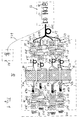
- FIG. 1 shows a block diagram of an apparatus 10 for monitoring reactions, which take place in a first plurality m of reaction vessels 18.
- These are removable vessels 18 the lower parts of which are positioned in respective chambers of e. g. four square vessel holders 11.1 to 11.4.
- Each of these vessel holders comprises a matrix like array of twenty-four chambers, each of these chambers being apt to receive the lower part of one of said vessels 18 which stands in upright position in that chamber.
- the vessel holders 11 have flat ground plates arranged in horizontal position. Each of this ground plates is preferably mechanically and thermally connected with a Peltier element which is used to carry out thermal cycles on the reaction vessels.
- the first plurality m of reaction vessels is consequently 96 as the product of a second plurality n being 24 (24 chambers per vessel holders) and of a third plurality p being 4 (4 vessel holders), but this is of course just an example and other suitable numbers can be chosen for each of the pluralities just mentioned.
- the apparatus 10 further comprises a light source 13, a network of different optic fibers, two sets of movable optical filters, a set of shutters, which in the following will be described in detail, and a set of multiple light receiving elements.
- the single, common light source 13 comprises a controlled electric halogen lamp 14 and optical means 15 comprising a set of lenses in order to form a light beam from the light emitted by the halogen lamp.
- the first set of optical filters comprises a fourth plurality q (e.g. four) of different interference filters 21.1 to 21.4, carried by a motor driven, rotatable wheel 22.
- the relative position of these filters with respect to the vessel holders is changeable and this makes possible allows to illuminate the sample-reagent mixtures contained in the reaction vessels with excitation light of different wavelengths and narrow bandwidth.
- Interference filters 21.1 to 21.4 are so arranged that they are apt to selectively cooperate with two optical units 31.1 to 31.4 and 32.1 to 32.4.
- Optical units 31.1 to 31.4 are needed for paralleling the light beams escaping from optic fibers 31.1 to 31.4 described below.
- second optical units 32.1 to 32.4 focus the light beams traversing the filters into further optic fibers 32.1 to 32.4 described below.
- the second set of optical filters has a structure similar to the one of the above mentioned first set of optical filters and comprises a fourth plurality q (e.g. four) of different second interference filters (23.1 to 23.4, carried by a second, motor driven, rotatable wheel 24.
- Interference filters 23.1 to 23.4 are so arranged that they are apt to selectively cooperate with two optical units 33.1 to 33.4 and 34.1 to 34.4 which serve for paralleling and for focusing light beams respectively.
- the first 21.1 to 21.4 and the second interference filters 23.1 to 23.4 are tuned by pairs with each other to allow transmission of specific pairs of excitation wavelengths and resulting fluorescence wavelengths.
- the network of optic fibers comprises three different kinds of optic fiber bundles.
- a first optic fiber bundle 41 is connected to the light source 13.
- Bundle 41 is composed of a thick main branch 41.1, which separates into four thinner adjoining branches 41.2 to 41.5, and a small test branch 41.6.
- the bundled end piece of bundle 41 takes up the light provided by the light source 13. This light is divided into five parts which are guided to the separated ends of the adjoining branches 41.2 to 41.5 and also to the separated end of test branch 41.6.
- the separated ends of branches 41.2 to 41.5 are close to said first optical units 31.1 to 31.4, respectively, the separated end of branch 41.6 is connected to a reference unit 43.
- Each of bundles 44.1 to 44.4 is composed of a relatively thick main branch 45 which splits up into twenty-four single, second, optic fibers 45.1 to 45.24.
- the main branches 45 take up the excitation light passing through filters 21.1 to 21.4, and the optic fibers 45.1 to 45.24 transmit excitation light to the reaction liquids contained in the reaction vessels 18.
- the third optic fiber bundles 46.1 to 46.4 are each formed of twenty-four third optic fibers 47.1 to 47.24. These third optic fibers are connected at one end individually to said reaction vessels 18 respectively to the chambers bearing these vessels, and at the opposite end the third fibers 47.1 to 47.24 are connected to the third optical units 31.1 to 31.4, respectively.
- the shutters 52.1 to 52.4 are arranged between said adjoining branches 41.2 to 41.5 of the first bundle 41 and said first optical units 31.1 to 31.4., or between said of second optical units 32.1 to 32.4 and said main branches 45 of said second bundles 44.1 to 44.4.
- the shutters are controllable individually and allow to interrupt the light paths between the light source 13 and the reaction vessels 18.
- the light receiving elements 51.1 to 51.4 are compact units of light receiving components and each of these units comprises, e.g. twenty-four light receiving elements so that each of these elements is assigned to one reaction vessel 18.
- the apparatus 10 operates as follows. A plurality of reaction vessels 18 are filled with liquid sample-reagent-mixtures, and positioned on vessel holders 11.1 to 11.4. The excitation light produced by the light source 13 is transmitted by the first bundle 41 to the first optical units 31.1 to 31.4 and to the reference unit 43. This unit 43 controls the luminous intensity of the lamp 14.
- the light escaping from the adjoining optic fiber branches 41.2 to 41.5 reaches the first optical units 31.1 to 31.4, which transmit light as beams of parallel light to the first interference filters 21.1 to 21.4 , which in turn transmit light to the second optical units 32.1 to 32.4, these transmit light to the second optic fiber bundles 44.1 to 44.4, and light eventually reaches the reaction vessels 18 as excitation light of four different kinds.
- These kinds differ by the wavelengths filtered out by filters 21.1 to 21.4 which filter different wavelength bands.
- the fluorescence light emitted by the excitated sample-reagent mixtures is collected individually by the third plurality of optic fibers 47.1 to 47.24 of the third optic fiber bundles 46.1 to 46.4.
- This fluorescence light is transmitted to the third optical units 33.1 to 33.4, through this units to the second interference filters 23.1 to 23.4 as beams of parallel light, is further transmitted to the fourth optical units 34.1 to 34.4, and reaches as focused beams individually assigned light receiving elements 51.1 to 51.4, these elements convert the fluorescence light beams into individual electric monitoring signals corresponding to the reaction vessels 18.
- the monitoring signals of all vessels 18 are obtained in parallel, i.e. simultaneously.
- the shutters 52.1 to 52.4 may be used to interrupt the excitation light as a whole or for one or the other of the light paths through said second bundles 44.1 to 44.4.
- the wheels 22 and 24 By turning the wheels 22 and 24 all the first and second interference filters 21.1 to 21.4, 23.1 to 23.4, respectively, will be changed synchronically and periodically.
- the wheels 22, 24 are rotatable separately, but in practice they are turned in synchronism.
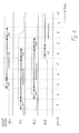
- Figure 2 shows a timetable for a typical process for using the first and second optical filters 21.1 to 21.4 and 23.1 to 23.4 in synchronism and for using the shutters 52.1 to 52.4.
- the time is running from left to right, divided in equal periods given by the stepwise rotation of the wheels 22, 24 bringing the interference filters 21.1 to 21.4 and 23.1 to 23.4 periodically into other positions.
- the excitation light is interrupted for all vessel holders 11.1 to 11.4.
- vessel holder 11.2 is ready for excitation, the excitation beginning at period 2 with excitation light passing filter 21.2, at period 3 the light passing filter 21.3, at period 4 the light passing filter 21.4, at period 5 the light passing filter 21.1, and at period 6 the excitation cycle being terminated for vessel holder 11.2.
- Independent excitation cycles beginning for vessel holder 11.3 at period 2, for vessel holder 11.1 at period 3 and for vessel holder 11.4 at period 6.
- the apparatus 10 allows at any time to excitate the sample-reagent mixtures reacting within the reaction vessels 18 stepwise with light of a desired quality and quantity.
- the resulting fluorescence light emitted is collected by the third optic fibers 47.1 to 47.24 and transmitted to the light receiving elements 51.1 to 51.4, which receivers emit associated monitoring signals.
Landscapes
- Chemical & Material Sciences (AREA)
- Health & Medical Sciences (AREA)
- Organic Chemistry (AREA)
- Life Sciences & Earth Sciences (AREA)
- Nuclear Medicine, Radiotherapy & Molecular Imaging (AREA)
- Physics & Mathematics (AREA)
- Chemical Kinetics & Catalysis (AREA)
- Analytical Chemistry (AREA)
- Biochemistry (AREA)
- General Health & Medical Sciences (AREA)
- General Physics & Mathematics (AREA)
- Immunology (AREA)
- Pathology (AREA)
- Investigating, Analyzing Materials By Fluorescence Or Luminescence (AREA)
- Investigating Or Analysing Materials By The Use Of Chemical Reactions (AREA)
Abstract
The apparatus (10) comprises four square vessel holders
(11.1 to 11.4) each of the holders taking up to twenty-four
removable reaction-vessels 18. The different holders allow
independent temperature cycles for the different groups of
vessels (18). A single light source (13) produces the
excitation light needed. A network of two different kinds of
optic fiber bundles (41, 45) transmits this light to the
reaction vessels through a first set of interference filters
(21.1 to 21.4), second optical units paralleling and
focusing the light, respectively. A test branch 41.6 of the
first bundle (41) is connected to a reference unit (43) for
control purposes. Fluorescence light emitted by sample-reaction-mixtures
is collected by third optic fibers (47)
and is transmitted through a second set of interference
filters (23.1 to 23.4) to individually assigned light
receiving elements (51). The filters are carried by wheels
(22, 24) which are rotated stepwise and in synchronism with
each other. This allows to change periodically the
wavelength of excitation light and the kind of monitoring.
The apparatus makes possible free handling of the vessel
holders (11.1 to 11.4) and random access to vessels to be
monitored.
Description
- The invention concerns a fluorescence measuring apparatus for simultaneously monitoring reactions taking place in a plurality of removable reaction vessels containing sample-reagent-mixtures apt to emit fluorescent light when illuminated by an excitation light.
- The apparatus also concerns a method of using such an apparatus.
- An apparatus for the automatic execution of temperature cycles is known from EP 0 642 831 A1. This apparatus comprises two independent circular vessel holders for each twelve reaction vessels, each of these vessels containing sample-reagent liquid mixtures of about 100 µl. These vessel holders are metallic and allow fast temperature cycling of sample-reagent liquid mixtures contained in said vessels by means of controlled Peltier elements. The holders may be used at different times and the cycles may be different, too.
- A system for real time detection of nucleic acid amplification products is known from WO 95/30139 A1. This system allows to carry out fluorescence-based measurements on a plurality of sample-reagent Liquid mixtures within small vessels at different, varying temperatures. The excitation light arrives the vessels from the top side via a fiber optic and a focal lens. The fluorescent light is collected via the same way in opposite direction and is transmitted to a centralized optical separation and analyses component. This component allows spectral analysis of the fluorescence light received.
- The above mentioned devices do not provide all performance features expected from analyzer systems needed today. Such systems are expected to offer a wide choice of possible optical configurations in order to enable the user to perform a large variety of possible tests. If this need is satisfied by multiplying the number of components in function of the number of reactions to be monitored, the result is a considerable increase of material required with a corresponding increase of costs.
- The aim of the invention is therefore to provide an apparatus of the above-mentioned type which offers a wide choice of possible optical measurement configurations and measurements with a minimum of components in order to limit costs.
- According to the invention this aim is attained with an apparatus which comprises
- (a) a plurality of groups of reaction vessels, each group being positioned in a corresponding vessel holder; each vessel holder allowing independent thermal cycling of the group of vessels it holds
- (b) a single light source,
- (c) a set of optical filters each of which is apt to be selectively positioned in the optical path linking the single light source to one of the groups of reaction vessels, and
- (d) a network of optical fibers for optically connecting said light source said optical filters, said plurality of groups of reaction vessels and a plurality of fluorescence light receiving means.
-
- A main advantage of the apparatus according to the invention is that it comprises a compact array for a large number of reaction vessels, which is suitable for performing different thermal cycling modes and excitation by light of different wave-lengths. The apparatus according to the invention is therefore in particular suitable for monitoring simultaneously reactions taking place in a large plurality of reaction vessels arranged in groups by means of fluorescence measurements. The monitoring can be carried out at any time and during different thermal cycling modes. The wavelength of the light used for excitation of the sample-reagent mixtures can be changed and can have e.g. four different values.
- Preferred embodiments of the invention are characterized by the features defined by
claims 2 to 12. - For a better understanding of the invention, preferred embodiments thereof are described in more detail hereinafter with reference to the accompanying drawings.
- Figure 1 shows a general block diagram of an apparatus for monitoring reactions.
- Figure 2 shows a timetable for a typical random access timing.
-
- Figure 1 shows a block diagram of an
apparatus 10 for monitoring reactions, which take place in a first plurality m ofreaction vessels 18. These areremovable vessels 18 the lower parts of which are positioned in respective chambers of e. g. four square vessel holders 11.1 to 11.4. Each of these vessel holders comprises a matrix like array of twenty-four chambers, each of these chambers being apt to receive the lower part of one of saidvessels 18 which stands in upright position in that chamber. Thevessel holders 11 have flat ground plates arranged in horizontal position. Each of this ground plates is preferably mechanically and thermally connected with a Peltier element which is used to carry out thermal cycles on the reaction vessels. The first plurality m of reaction vessels is consequently 96 as the product of a second plurality n being 24 (24 chambers per vessel holders) and of a third plurality p being 4 (4 vessel holders), but this is of course just an example and other suitable numbers can be chosen for each of the pluralities just mentioned. - The
apparatus 10 further comprises alight source 13, a network of different optic fibers, two sets of movable optical filters, a set of shutters, which in the following will be described in detail, and a set of multiple light receiving elements. - The single,
common light source 13 comprises a controlled electric halogen lamp 14 andoptical means 15 comprising a set of lenses in order to form a light beam from the light emitted by the halogen lamp. - The first set of optical filters comprises a fourth plurality q (e.g. four) of different interference filters 21.1 to 21.4, carried by a motor driven,
rotatable wheel 22. The relative position of these filters with respect to the vessel holders is changeable and this makes possible allows to illuminate the sample-reagent mixtures contained in the reaction vessels with excitation light of different wavelengths and narrow bandwidth. - Interference filters 21.1 to 21.4 are so arranged that they are apt to selectively cooperate with two optical units 31.1 to 31.4 and 32.1 to 32.4. Optical units 31.1 to 31.4 are needed for paralleling the light beams escaping from optic fibers 31.1 to 31.4 described below. At the opposite side of filters 21.1 to 21.4 second optical units 32.1 to 32.4 focus the light beams traversing the filters into further optic fibers 32.1 to 32.4 described below.
- The second set of optical filters has a structure similar to the one of the above mentioned first set of optical filters and comprises a fourth plurality q (e.g. four) of different second interference filters (23.1 to 23.4, carried by a second, motor driven,
rotatable wheel 24. Interference filters 23.1 to 23.4 are so arranged that they are apt to selectively cooperate with two optical units 33.1 to 33.4 and 34.1 to 34.4 which serve for paralleling and for focusing light beams respectively. - The first 21.1 to 21.4 and the second interference filters 23.1 to 23.4 are tuned by pairs with each other to allow transmission of specific pairs of excitation wavelengths and resulting fluorescence wavelengths.
- The network of optic fibers comprises three different kinds of optic fiber bundles. A first
optic fiber bundle 41 is connected to thelight source 13.Bundle 41 is composed of a thick main branch 41.1, which separates into four thinner adjoining branches 41.2 to 41.5, and a small test branch 41.6. The bundled end piece ofbundle 41 takes up the light provided by thelight source 13. This light is divided into five parts which are guided to the separated ends of the adjoining branches 41.2 to 41.5 and also to the separated end of test branch 41.6. The separated ends of branches 41.2 to 41.5 are close to said first optical units 31.1 to 31.4, respectively, the separated end of branch 41.6 is connected to areference unit 43. - Four second identical optic fiber bundles 44.1 to 44.4 are arranged between the second optical units 32.1 to 32.4 and the
reaction vessels 18 positioned on vessel holders 11.1 to 11.4 as shown by Fig. 1. Each of bundles 44.1 to 44.4 is composed of a relatively thick main branch 45 which splits up into twenty-four single, second, optic fibers 45.1 to 45.24. The main branches 45 take up the excitation light passing through filters 21.1 to 21.4, and the optic fibers 45.1 to 45.24 transmit excitation light to the reaction liquids contained in thereaction vessels 18. - The third optic fiber bundles 46.1 to 46.4 are each formed of twenty-four third optic fibers 47.1 to 47.24. These third optic fibers are connected at one end individually to said
reaction vessels 18 respectively to the chambers bearing these vessels, and at the opposite end the third fibers 47.1 to 47.24 are connected to the third optical units 31.1 to 31.4, respectively. - The shutters 52.1 to 52.4 are arranged between said adjoining branches 41.2 to 41.5 of the
first bundle 41 and said first optical units 31.1 to 31.4., or between said of second optical units 32.1 to 32.4 and said main branches 45 of said second bundles 44.1 to 44.4. - The shutters are controllable individually and allow to interrupt the light paths between the
light source 13 and thereaction vessels 18. - In a preferred embodiment the light receiving elements 51.1 to 51.4 are compact units of light receiving components and each of these units comprises, e.g. twenty-four light receiving elements so that each of these elements is assigned to one
reaction vessel 18. - The
apparatus 10 operates as follows. A plurality ofreaction vessels 18 are filled with liquid sample-reagent-mixtures, and positioned on vessel holders 11.1 to 11.4. The excitation light produced by thelight source 13 is transmitted by thefirst bundle 41 to the first optical units 31.1 to 31.4 and to thereference unit 43. Thisunit 43 controls the luminous intensity of the lamp 14. - The light escaping from the adjoining optic fiber branches 41.2 to 41.5 reaches the first optical units 31.1 to 31.4, which transmit light as beams of parallel light to the first interference filters 21.1 to 21.4 , which in turn transmit light to the second optical units 32.1 to 32.4, these transmit light to the second optic fiber bundles 44.1 to 44.4, and light eventually reaches the
reaction vessels 18 as excitation light of four different kinds. These kinds differ by the wavelengths filtered out by filters 21.1 to 21.4 which filter different wavelength bands. - The fluorescence light emitted by the excitated sample-reagent mixtures is collected individually by the third plurality of optic fibers 47.1 to 47.24 of the third optic fiber bundles 46.1 to 46.4. This fluorescence light is transmitted to the third optical units 33.1 to 33.4, through this units to the second interference filters 23.1 to 23.4 as beams of parallel light, is further transmitted to the fourth optical units 34.1 to 34.4, and reaches as focused beams individually assigned light receiving elements 51.1 to 51.4, these elements convert the fluorescence light beams into individual electric monitoring signals corresponding to the
reaction vessels 18. The monitoring signals of allvessels 18 are obtained in parallel, i.e. simultaneously. - The shutters 52.1 to 52.4 may be used to interrupt the excitation light as a whole or for one or the other of the light paths through said second bundles 44.1 to 44.4. By turning the
wheels wheels - Figure 2 shows a timetable for a typical process for using the first and second optical filters 21.1 to 21.4 and 23.1 to 23.4 in synchronism and for using the shutters 52.1 to 52.4. The time is running from left to right, divided in equal periods given by the stepwise rotation of the
wheels period 1 vessel holder 11.2 is ready for excitation, the excitation beginning atperiod 2 with excitation light passing filter 21.2, at period 3 the light passing filter 21.3, at period 4 the light passing filter 21.4, atperiod 5 the light passing filter 21.1, and atperiod 6 the excitation cycle being terminated for vessel holder 11.2. Independent excitation cycles beginning for vessel holder 11.3 atperiod 2, for vessel holder 11.1 at period 3 and for vessel holder 11.4 atperiod 6. - The independence of the different cycles of excitation for the different vessel holders 11.1 to 11.4 gives full freedom for managing different groups of
reaction vessels 18 referring to time of preparation, to method of handling, especially to temperature profile used, etc. - Said freedom is very important for the daily practical use of
apparatus 10. Thus theapparatus 10 allows at any time to excitate the sample-reagent mixtures reacting within thereaction vessels 18 stepwise with light of a desired quality and quantity. The resulting fluorescence light emitted is collected by the third optic fibers 47.1 to 47.24 and transmitted to the light receiving elements 51.1 to 51.4, which receivers emit associated monitoring signals. - It is important, that the excitating light at any time is interruptable without switching off the
light source 13 by said shutters 52.1 to 52.4. This allows e. g. short excitation periods between long dark periods. - There are a lot of variants within the general idea of the invention. The most important variants will be nominated in the following:
- There may be more or less than four vessel holders 11.1 to
11.4 and more or less than twenty-four
reaction vessels 18 perholder 11. - The kind of the first and second optical filters 21.1 to
21.4; 23.1 to 23.4 is free. Preferred four different
interference filters are used, but one of the filters may
be totally transparent, two of the filters may be equal,
or a plurality q other than four is provided, e.g. five
filters per
wheel - The light beams traversing the filters 21.1 to 21.4; 23.1 to 23.4 may be more or less broad. Said optical units 31, 32, 33, 34 may be equal or different in their construction.
- The
filter wheels - The second filters 23.1 to 23.4 may be deleted to get the full fluorescence spectrum for monitoring.
- Additional shutters can be arranged between optic fiber branches 46.1 to 46.4 and optical units (33.1 to 33.4) in order to protect light receivers, like e.g. photomultiplier tubes, from unnecessary and destructive illumination.
Claims (12)
- A fluorescence measuring apparatus (10) for simultaneously monitoring reactions taking place in a plurality of removable reaction vessels containing sample-reagent-mixtures apt to emit fluorescent light when illuminated by an excitation light, said apparatus comprising:(a) a plurality of groups of reaction vessels, each group being positioned in a corresponding vessel holder (11.1 to 11.4); each vessel holder allowing independent thermal cycling of the group of vessels it holds(b) a single light source (13),(c) a first movable set of optical filters (21.1 to 21.4) each of which is apt to be selectively positioned in the optical path linking the single light source (13) to one of the groups of reaction vessels, and(d) a network of optic fibers for optically connecting said light source (13), said optical filters (21.1 to 21.4), said plurality of groups of reaction vessels (18) and a plurality of fluorescence light receiving means (51.1 to 51.4)
- An apparatus according to claim 1, wherein said light source (13) comprises a controlled halogen lamp (14) and optical means (15) optically connected thereto for forming an excitation light beam.
- An apparatus according to claim 1, wherein said network of optic fibers comprisesa first bundle (41) of optic fibers dividing from a single main branch (41.1) which is optically connected to said light source (13) into a third plurality (p) of equal adjoining branches (41.2 to 41.5) connected to said set of optical filters (21.1 to 21.4), and dividing into an additional branch (41.6) connected to a reference unit (43),a plurality (p) of second bundles (44.1 to 44.4) of optic fibers each of which divides from a single branch (45) connected to one of said optical filters (21.1 to 21.4) into a second plurality (n) of equal second fibers (45.1 to 45.24), each of which is connected to one of said reaction vessels (18) positioned on one of said vessel holders (11.1 to 11.4), anda plurality (p) of third bundles (46.1 to 46.4) of optic fibers each of which bundles is formed by a second plurality (n) of third optic fibers (47.1 to 47.24) connecting said reaction vessels (18) of each of said vessel groups positioned on one of said vessel holders (11.1 to 11.4) with an individually assigned fluorescence light receiving element (51.1 to 51.4).
- An apparatus according to claims 1 and 3, wherein said set of optical filters (21.1 to 21.4) comprisesa rotatable wheel (22) for carrying said a plurality (q) of optical filters (21.1 to 21.4),a plurality (p) of first optical units (31.1 to 31.4) for paralleling the light beams escaping said adjoining branches (41.2 to 41.5) of said first bundle (41) and transmitting said optical filters (21.1 to 21.4), anda plurality of second optical units (32.1 to 32.4) for focusing said light beams transmitting said optical filters (21.1 to 21.4) into said main branches (45) of said second bundles (44.1 to 44.4).
- An apparatus according to claims 1 and 4, wherein
a plurality (p) of controlled shutters (52.1 to 52.4) is provided between said adjoining branches (41.2 to 41.5) of said first bundle (41) and said plurality of first optical units (31.1 to 31.4), or between said plurality of second optical units (32.1 to 32.4) and said main branches (45) of said second bundles (44.1 to 44.4), to interrupt individually said excitation light. - An apparatus according to claims 1 to 5, wherein a second set of movable optical filters (23.1 to 23.4) is provided between said third bundles (46.1 to 46.4) and said fluorescence light receiving elements (51.1 to 51.4), and a second rotatable wheel (24) carries said second set of optical filters (23.1 to 23.4).
- An apparatus according to claims 1 and 6, wherein said first set of movable filters (21.1 to 21.4) and said second set of movable filters (23.1 to 23.4) are interference filters, one filter of the first set and one filter of the second set being tuned by pairs with each other.
- An apparatus according to claims 1 and 6, wherein
rotation of said first wheel (22) and rotation of said second wheel (24) are controlled individually and/or are synchronized with each other. - An apparatus according to claim 1, wherein said vessel holders (11.1 to 11.4) are arranged in a same plane.
- An apparatus according to claims 1 to 9, wherein
the plurality of reaction vessels which can be monitored in the apparatus comprises 96 vessels, the plurality of vessels of a group of vessels comprises 24 vessels, the plurality of vessel holders comprises 4 vessel holders and the plurality of different excitation wavelengths comprises 4 wavelengths. - Method for using apparatus 10 according to any of claims 1 to 10, wherein
said different vessel holders (11.1 to 11.4) are used to take up different groups of said reaction vessels (18), and each said groups being excitable by said excitation light at any time independent of the other said groups. - Method according to claim 11, wherein
the wave-length of the excitation light applied to a group of reaction vessels is changed periodically by changing the relative position of said set of filters (21.1 to 21.4), said change of relative position being obtained by stepwise rotation of said wheel (22) carrying said filters.
Priority Applications (1)
| Application Number | Priority Date | Filing Date | Title |
|---|---|---|---|
| EP98810396A EP0953838A1 (en) | 1998-05-01 | 1998-05-01 | Apparatus for simultaneously monitoring reactions taking place in a plurality of reaction vessels |
Applications Claiming Priority (1)
| Application Number | Priority Date | Filing Date | Title |
|---|---|---|---|
| EP98810396A EP0953838A1 (en) | 1998-05-01 | 1998-05-01 | Apparatus for simultaneously monitoring reactions taking place in a plurality of reaction vessels |
Publications (1)
| Publication Number | Publication Date |
|---|---|
| EP0953838A1 true EP0953838A1 (en) | 1999-11-03 |
Family
ID=8236071
Family Applications (1)
| Application Number | Title | Priority Date | Filing Date |
|---|---|---|---|
| EP98810396A Withdrawn EP0953838A1 (en) | 1998-05-01 | 1998-05-01 | Apparatus for simultaneously monitoring reactions taking place in a plurality of reaction vessels |
Country Status (1)
| Country | Link |
|---|---|
| EP (1) | EP0953838A1 (en) |
Cited By (25)
| Publication number | Priority date | Publication date | Assignee | Title |
|---|---|---|---|---|
| GB2404015A (en) * | 2003-06-06 | 2005-01-19 | Bosch Gmbh Robert | Apparatus and method for analysing a material library |
| WO2005066597A1 (en) * | 2003-12-19 | 2005-07-21 | 3M Innovative Properties Company | Multiplexing rotary spectrometer |
| WO2008011875A1 (en) * | 2006-07-28 | 2008-01-31 | Analytik Jena Ag | Arrangement and method for multichannel fluorescence measurement in pcr samples |
| EP1962084A1 (en) * | 2007-02-21 | 2008-08-27 | Roche Diagnostics GmbH | Apparatus for emitting and detecting beams of light |
| EP2511693A1 (en) | 2011-04-13 | 2012-10-17 | F. Hoffmann-La Roche AG | Analysis System with a spectrally controlled light source |
| US8797526B2 (en) | 2010-11-15 | 2014-08-05 | Roche Diagnostics Operations, Inc. | Instrument and method for the automated thermal treatment of liquid samples |
| US8840848B2 (en) | 2010-07-23 | 2014-09-23 | Beckman Coulter, Inc. | System and method including analytical units |
| US8973736B2 (en) | 2011-11-07 | 2015-03-10 | Beckman Coulter, Inc. | Magnetic damping for specimen transport system |
| US9046506B2 (en) | 2011-11-07 | 2015-06-02 | Beckman Coulter, Inc. | Specimen container detection |
| US9089828B2 (en) | 2009-01-08 | 2015-07-28 | It-Is International Limited | Optical system for chemical and/or biochemical reactions |
| US9446418B2 (en) | 2011-11-07 | 2016-09-20 | Beckman Coulter, Inc. | Robotic arm |
| US9482684B2 (en) | 2011-11-07 | 2016-11-01 | Beckman Coulter, Inc. | Centrifuge system and workflow |
| US9482613B2 (en) | 2011-05-16 | 2016-11-01 | Roche Molecular Systems, Inc. | Instrument and method for detecting analytes |
| US9506943B2 (en) | 2011-11-07 | 2016-11-29 | Beckman Coulter, Inc. | Aliquotter system and workflow |
| DE102016200271A1 (en) * | 2016-01-13 | 2017-07-13 | Institut Dr. Foerster Gmbh & Co. Kg | Device for generating and measuring an emission |
| US9910054B2 (en) | 2011-11-07 | 2018-03-06 | Beckman Coulter, Inc. | System and method for processing samples |
| EP2320027B1 (en) * | 2009-11-06 | 2019-07-31 | Precision Energy Services, Inc. | Movable filter assembly for downhole spectroscopy |
| US10444143B2 (en) | 2014-06-27 | 2019-10-15 | Valmet Automation Oy | Optical multi-channel measurement unit, optical multi-channel detector unit and a measurement method for measuring a property of an object |
| DE102018111033A1 (en) * | 2018-05-08 | 2019-11-14 | Byonoy Gmbh | Transmission device for the examination of samples in wells of a microtiter plate and method for examining samples in wells of a microtiter plate by means of transmission |
| CN111022997A (en) * | 2019-12-24 | 2020-04-17 | 冠牌光电智能科技湖北股份有限公司 | LED court street lamp with training function |
| WO2021201597A1 (en) | 2020-03-31 | 2021-10-07 | Seegene, Inc. | Optical signal detection device |
| US11209349B2 (en) * | 2017-02-24 | 2021-12-28 | Pietro Fiorentini (USA), Inc. | Optical fluid analyzer |
| US20220244181A1 (en) * | 2019-05-31 | 2022-08-04 | Seegene, Inc. | Method for detecting target nucleic acid in sample |
| CN115718094A (en) * | 2021-08-24 | 2023-02-28 | 深圳迈瑞生物医疗电子股份有限公司 | Sample analysis device and sample analysis method |
| DE102023122562A1 (en) * | 2023-08-23 | 2025-02-27 | Clemens Gmbh | Method for recording fluorescence signals for a laboratory device and laboratory device |
Citations (7)
| Publication number | Priority date | Publication date | Assignee | Title |
|---|---|---|---|---|
| WO1983000384A1 (en) * | 1981-07-20 | 1983-02-03 | American Hospital Supply Corp | Multichannel spectrophotometer |
| EP0109536A1 (en) * | 1982-10-15 | 1984-05-30 | Kabushiki Kaisha Toshiba | Apparatus for absorptiometric analysis |
| JPS6039533A (en) * | 1983-08-12 | 1985-03-01 | Japan Spectroscopic Co | Spectrochemical analysis device with microplate |
| WO1993013423A1 (en) * | 1991-12-20 | 1993-07-08 | The Salk Institute Biotechnology/Industrial Associates, Inc. | Automated analysis equipment and assay method for detecting cell surface protein and/or cytoplasmic receptor function using same |
| EP0583066A1 (en) * | 1992-07-17 | 1994-02-16 | Becton, Dickinson and Company | Methods and apparatus for detecting bacterial growth by spectrophotometric sampling of a fibre-optic array |
| EP0640826A1 (en) * | 1993-08-27 | 1995-03-01 | Becton, Dickinson and Company | System for detecting bacterial growth in a plurality of culture vials |
| WO1995030139A1 (en) * | 1994-04-29 | 1995-11-09 | Perkin-Elmer Corporation | System for real time detection of nucleic acid amplification products |
-
1998
- 1998-05-01 EP EP98810396A patent/EP0953838A1/en not_active Withdrawn
Patent Citations (7)
| Publication number | Priority date | Publication date | Assignee | Title |
|---|---|---|---|---|
| WO1983000384A1 (en) * | 1981-07-20 | 1983-02-03 | American Hospital Supply Corp | Multichannel spectrophotometer |
| EP0109536A1 (en) * | 1982-10-15 | 1984-05-30 | Kabushiki Kaisha Toshiba | Apparatus for absorptiometric analysis |
| JPS6039533A (en) * | 1983-08-12 | 1985-03-01 | Japan Spectroscopic Co | Spectrochemical analysis device with microplate |
| WO1993013423A1 (en) * | 1991-12-20 | 1993-07-08 | The Salk Institute Biotechnology/Industrial Associates, Inc. | Automated analysis equipment and assay method for detecting cell surface protein and/or cytoplasmic receptor function using same |
| EP0583066A1 (en) * | 1992-07-17 | 1994-02-16 | Becton, Dickinson and Company | Methods and apparatus for detecting bacterial growth by spectrophotometric sampling of a fibre-optic array |
| EP0640826A1 (en) * | 1993-08-27 | 1995-03-01 | Becton, Dickinson and Company | System for detecting bacterial growth in a plurality of culture vials |
| WO1995030139A1 (en) * | 1994-04-29 | 1995-11-09 | Perkin-Elmer Corporation | System for real time detection of nucleic acid amplification products |
Non-Patent Citations (1)
| Title |
|---|
| PATENT ABSTRACTS OF JAPAN vol. 009, no. 163 (P - 371) 9 July 1985 (1985-07-09) * |
Cited By (53)
| Publication number | Priority date | Publication date | Assignee | Title |
|---|---|---|---|---|
| US7479636B2 (en) | 2003-06-06 | 2009-01-20 | Robert Bosch Gmbh | Device and method for analyzing a materials library |
| GB2404015A (en) * | 2003-06-06 | 2005-01-19 | Bosch Gmbh Robert | Apparatus and method for analysing a material library |
| GB2404015B (en) * | 2003-06-06 | 2006-03-22 | Bosch Gmbh Robert | Apparatus and method for analysing a material library |
| US7113282B2 (en) | 2003-12-19 | 2006-09-26 | 3M Innonative Properties Company | Multiplexing rotary spectrometer |
| WO2005066597A1 (en) * | 2003-12-19 | 2005-07-21 | 3M Innovative Properties Company | Multiplexing rotary spectrometer |
| WO2008011875A1 (en) * | 2006-07-28 | 2008-01-31 | Analytik Jena Ag | Arrangement and method for multichannel fluorescence measurement in pcr samples |
| EP1962084A1 (en) * | 2007-02-21 | 2008-08-27 | Roche Diagnostics GmbH | Apparatus for emitting and detecting beams of light |
| EP1962085A3 (en) * | 2007-02-21 | 2008-09-24 | Roche Diagnostics GmbH | Apparatus for emitting and detecting beams of light |
| US7947442B2 (en) | 2007-02-21 | 2011-05-24 | Roche Molecular Systems, Inc. | Apparatus for emitting and detecting light in a nucleic acid amplification reaction |
| EP3889586A1 (en) | 2009-01-08 | 2021-10-06 | IT-IS International Ltd | Optical system for chemical and/or biochemical reactions |
| US10029227B2 (en) | 2009-01-08 | 2018-07-24 | It-Is International Limited | Optical system for chemical and/or biochemical reactions |
| US9089828B2 (en) | 2009-01-08 | 2015-07-28 | It-Is International Limited | Optical system for chemical and/or biochemical reactions |
| EP2584344B1 (en) | 2009-01-08 | 2021-06-30 | IT-IS International Limited | Optical system for detecting light from polymerase chain reactions |
| EP2320027B1 (en) * | 2009-11-06 | 2019-07-31 | Precision Energy Services, Inc. | Movable filter assembly for downhole spectroscopy |
| US8962308B2 (en) | 2010-07-23 | 2015-02-24 | Beckman Coulter, Inc. | System and method including thermal cycler modules |
| US9274132B2 (en) | 2010-07-23 | 2016-03-01 | Beckman Coulter, Inc. | Assay cartridge with reaction well |
| US8996320B2 (en) | 2010-07-23 | 2015-03-31 | Beckman Coulter, Inc. | System and method including analytical units |
| US9046455B2 (en) | 2010-07-23 | 2015-06-02 | Beckman Coulter, Inc. | System and method including multiple processing lanes executing processing protocols |
| US8956570B2 (en) | 2010-07-23 | 2015-02-17 | Beckman Coulter, Inc. | System and method including analytical units |
| US8932541B2 (en) | 2010-07-23 | 2015-01-13 | Beckman Coulter, Inc. | Pipettor including compliant coupling |
| US9140715B2 (en) | 2010-07-23 | 2015-09-22 | Beckman Coulter, Inc. | System and method for controlling thermal cycler modules |
| US9519000B2 (en) | 2010-07-23 | 2016-12-13 | Beckman Coulter, Inc. | Reagent cartridge |
| US9285382B2 (en) | 2010-07-23 | 2016-03-15 | Beckman Coulter, Inc. | Reaction vessel |
| US8840848B2 (en) | 2010-07-23 | 2014-09-23 | Beckman Coulter, Inc. | System and method including analytical units |
| US8797526B2 (en) | 2010-11-15 | 2014-08-05 | Roche Diagnostics Operations, Inc. | Instrument and method for the automated thermal treatment of liquid samples |
| US9956559B2 (en) | 2010-11-15 | 2018-05-01 | Roche Molecular Systems, Inc. | Instrument and method for the automated thermal treatment of liquid samples |
| US9557269B2 (en) | 2010-11-15 | 2017-01-31 | Roche Molecular Systems, Inc. | Instrument and method for the automated thermal treatment of liquid samples |
| EP2511693A1 (en) | 2011-04-13 | 2012-10-17 | F. Hoffmann-La Roche AG | Analysis System with a spectrally controlled light source |
| US9482613B2 (en) | 2011-05-16 | 2016-11-01 | Roche Molecular Systems, Inc. | Instrument and method for detecting analytes |
| US10393659B2 (en) | 2011-05-16 | 2019-08-27 | Roche Molecular Systems, Inc. | Instrument and method for detecting analytes |
| US9046506B2 (en) | 2011-11-07 | 2015-06-02 | Beckman Coulter, Inc. | Specimen container detection |
| US9482684B2 (en) | 2011-11-07 | 2016-11-01 | Beckman Coulter, Inc. | Centrifuge system and workflow |
| US10048284B2 (en) | 2011-11-07 | 2018-08-14 | Beckman Coulter, Inc. | Sample container cap with centrifugation status indicator device |
| US10274505B2 (en) | 2011-11-07 | 2019-04-30 | Beckman Coulter, Inc. | Robotic arm |
| US9446418B2 (en) | 2011-11-07 | 2016-09-20 | Beckman Coulter, Inc. | Robotic arm |
| US9910054B2 (en) | 2011-11-07 | 2018-03-06 | Beckman Coulter, Inc. | System and method for processing samples |
| US8973736B2 (en) | 2011-11-07 | 2015-03-10 | Beckman Coulter, Inc. | Magnetic damping for specimen transport system |
| US9506943B2 (en) | 2011-11-07 | 2016-11-29 | Beckman Coulter, Inc. | Aliquotter system and workflow |
| US10444143B2 (en) | 2014-06-27 | 2019-10-15 | Valmet Automation Oy | Optical multi-channel measurement unit, optical multi-channel detector unit and a measurement method for measuring a property of an object |
| DE102016200271A1 (en) * | 2016-01-13 | 2017-07-13 | Institut Dr. Foerster Gmbh & Co. Kg | Device for generating and measuring an emission |
| US10605732B2 (en) | 2016-01-13 | 2020-03-31 | Institut Dr. Foerster Gmbh & Co. Kg | Portable device for detecting explosive substances comprising a device for generating and measuring the emission of an indicator |
| US11209349B2 (en) * | 2017-02-24 | 2021-12-28 | Pietro Fiorentini (USA), Inc. | Optical fluid analyzer |
| DE102018111033A1 (en) * | 2018-05-08 | 2019-11-14 | Byonoy Gmbh | Transmission device for the examination of samples in wells of a microtiter plate and method for examining samples in wells of a microtiter plate by means of transmission |
| US20220244181A1 (en) * | 2019-05-31 | 2022-08-04 | Seegene, Inc. | Method for detecting target nucleic acid in sample |
| CN111022997B (en) * | 2019-12-24 | 2021-10-29 | 冠牌光电智能科技湖北股份有限公司 | LED court street lamp with training function |
| CN111022997A (en) * | 2019-12-24 | 2020-04-17 | 冠牌光电智能科技湖北股份有限公司 | LED court street lamp with training function |
| WO2021201597A1 (en) | 2020-03-31 | 2021-10-07 | Seegene, Inc. | Optical signal detection device |
| US20230137550A1 (en) * | 2020-03-31 | 2023-05-04 | Seegene, Inc. | Optical signal detection device |
| EP4127677A4 (en) * | 2020-03-31 | 2024-04-24 | Seegene, Inc. | OPTICAL SIGNAL DETECTION DEVICE |
| US12546720B2 (en) * | 2020-03-31 | 2026-02-10 | Seegene, Inc. | Optical signal detection device comprising sample holder divided into sample areas and light source units dedicated thereto |
| CN115718094A (en) * | 2021-08-24 | 2023-02-28 | 深圳迈瑞生物医疗电子股份有限公司 | Sample analysis device and sample analysis method |
| DE102023122562A1 (en) * | 2023-08-23 | 2025-02-27 | Clemens Gmbh | Method for recording fluorescence signals for a laboratory device and laboratory device |
| DE102023122562B4 (en) * | 2023-08-23 | 2025-04-24 | Clemens Gmbh | Method for recording fluorescence signals for a laboratory device and laboratory device |
Similar Documents
| Publication | Publication Date | Title |
|---|---|---|
| EP0953838A1 (en) | Apparatus for simultaneously monitoring reactions taking place in a plurality of reaction vessels | |
| EP1830174B1 (en) | Multi-channel fluorescence sample analyzer | |
| EP2376896B1 (en) | Optical system for chemical and/or biochemical reactions | |
| EP2201352B1 (en) | Fluorescence excitation and detection system and method | |
| US4601537A (en) | Apparatus and methods for forming images and for optical demultiplexing | |
| US8696992B2 (en) | Optical fiber measurement device and measurement method using same | |
| US20020070350A1 (en) | Imaging | |
| WO1996018115A1 (en) | Fluorescence detection apparatus | |
| CA2267622C (en) | Apparatus for simultaneously monitoring reactions taking place in a plurality of reaction vessels | |
| WO2001004608A1 (en) | Light detection device | |
| US20100007877A1 (en) | Narrow-band spectrometric Measurements | |
| US7113285B2 (en) | Multimode reader | |
| CA2331678A1 (en) | Multi-channel optical detection system | |
| WO2014210593A1 (en) | Devices for real-time polymerase chain reaction | |
| EP1348120B1 (en) | Luminescence imager | |
| KR20040048754A (en) | Temperature controlled real time fluorescence detection apparatus | |
| CA2284195A1 (en) | Device and method for capillary electrophoresis | |
| JPH10221242A (en) | Multi-titer plate analyzer | |
| WO2010134104A1 (en) | Modular multi-band fluorescence excitation system. | |
| US20050157299A1 (en) | Optical analysis systems | |
| WO2005069843A2 (en) | Optical analysis systems | |
| CN114276912A (en) | Fluorescence detection system, method and PCR amplification analysis device | |
| CN116790362A (en) | Probe coded liquid drop fluorescence excitation detection equipment | |
| GB2568307A (en) | Spectral excitation device |
Legal Events
| Date | Code | Title | Description |
|---|---|---|---|
| PUAI | Public reference made under article 153(3) epc to a published international application that has entered the european phase |
Free format text: ORIGINAL CODE: 0009012 |
|
| AK | Designated contracting states |
Kind code of ref document: A1 Designated state(s): AT BE CH CY DE DK ES FI FR GB GR IE IT LI LU MC NL PT SE |
|
| AX | Request for extension of the european patent |
Free format text: AL;LT;LV;MK;RO;SI |
|
| AKX | Designation fees paid | ||
| REG | Reference to a national code |
Ref country code: DE Ref legal event code: 8566 |
|
| STAA | Information on the status of an ep patent application or granted ep patent |
Free format text: STATUS: THE APPLICATION IS DEEMED TO BE WITHDRAWN |
|
| 18D | Application deemed to be withdrawn |
Effective date: 20000504 |