EP0953371B1 - Sealing arrangement for filter belt - Google Patents
Sealing arrangement for filter belt Download PDFInfo
- Publication number
- EP0953371B1 EP0953371B1 EP99103082A EP99103082A EP0953371B1 EP 0953371 B1 EP0953371 B1 EP 0953371B1 EP 99103082 A EP99103082 A EP 99103082A EP 99103082 A EP99103082 A EP 99103082A EP 0953371 B1 EP0953371 B1 EP 0953371B1
- Authority
- EP
- European Patent Office
- Prior art keywords
- liquid
- tank
- conduits
- opposed side
- section
- Prior art date
- Legal status (The legal status is an assumption and is not a legal conclusion. Google has not performed a legal analysis and makes no representation as to the accuracy of the status listed.)
- Expired - Lifetime
Links
- 238000007789 sealing Methods 0.000 title description 16
- 239000007788 liquid Substances 0.000 claims description 42
- 239000012530 fluid Substances 0.000 claims description 18
- 230000004888 barrier function Effects 0.000 claims description 5
- 238000001914 filtration Methods 0.000 claims description 5
- 230000000712 assembly Effects 0.000 claims description 4
- 238000000429 assembly Methods 0.000 claims description 4
- 230000033001 locomotion Effects 0.000 claims description 4
- 239000007787 solid Substances 0.000 claims description 4
- 238000007667 floating Methods 0.000 claims description 3
- 239000011236 particulate material Substances 0.000 claims description 3
- 230000003134 recirculating effect Effects 0.000 claims description 2
- 230000002708 enhancing effect Effects 0.000 claims 1
- 239000013618 particulate matter Substances 0.000 description 3
- 230000000052 comparative effect Effects 0.000 description 2
- 230000010006 flight Effects 0.000 description 2
- 238000004140 cleaning Methods 0.000 description 1
- 238000010276 construction Methods 0.000 description 1
- 239000011152 fibreglass Substances 0.000 description 1
- 238000003754 machining Methods 0.000 description 1
- 239000000463 material Substances 0.000 description 1
- 239000013528 metallic particle Substances 0.000 description 1
- 238000005555 metalworking Methods 0.000 description 1
- 238000000034 method Methods 0.000 description 1
- 230000004048 modification Effects 0.000 description 1
- 238000012986 modification Methods 0.000 description 1
- 239000004033 plastic Substances 0.000 description 1
- 239000013589 supplement Substances 0.000 description 1
- XLYOFNOQVPJJNP-UHFFFAOYSA-N water Substances O XLYOFNOQVPJJNP-UHFFFAOYSA-N 0.000 description 1
Images


Classifications
-
- B—PERFORMING OPERATIONS; TRANSPORTING
- B01—PHYSICAL OR CHEMICAL PROCESSES OR APPARATUS IN GENERAL
- B01D—SEPARATION
- B01D29/00—Filters with filtering elements stationary during filtration, e.g. pressure or suction filters, not covered by groups B01D24/00 - B01D27/00; Filtering elements therefor
- B01D29/09—Filters with filtering elements stationary during filtration, e.g. pressure or suction filters, not covered by groups B01D24/00 - B01D27/00; Filtering elements therefor with filtering bands, e.g. movable between filtering operations
- B01D29/096—Construction of filtering bands or supporting belts, e.g. devices for centering, mounting or sealing the filtering bands or the supporting belts
Definitions
- the present invention relates to an improved apparatus for filtering particulate materials from a dirty fluid stream which is passed through a flight of an endless filter medium belt or a strip of continuously fed filter medium with a portion of the recirculated clean fluid being utilized along the side edges of the filter medium for sealing.
- Patents, No. 4,481,108 and No. 5,601,729 issured to Jack R. Bratten on November 6, 1984 and February 11, 1997, respectively, the use of disclosed wear inflicting, inflatable sealing tubes has been relied upon for sealing side edge sealing of filter medium, necessarily resulting in the aforedescribed undue wear of the filter medium. Also in these aforementioned patents the major problem of solids by-passing the medium from the dirty to the clean side of the system, occurs during the indexing movement of the filter medium when the sealing tubes have been deflated to permit filter medium movement.
- the present invention recognizing certain of the problems recognized by the prior art, as well as problems created by prior art solutions, avoids the same with a unique structure and method which is straightforward and economical in construction, operation and maintenance-requiring a comparative minimum of parts and a comparative minimum of steps in resolving prior art difficulties. Further, the present invention uniquely utilizes the sealing machinery itself, to further supplement the novel sealing arrangement of the present invention.
- the present invention provides a fluid filter apparatus according to claim 1.
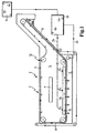
- Filter apparatus 2 includes a horizontally extending dirty liquid receiving tank 3 which incorporates an upper first section 4 disposed between the opposed side walls of tank 3 to receive a dirty liquid stream carrying particulate matter to be separated by a suitable filter medium described in more detail hereinafter.
- a lower second section 6 below first section 4 and also between the opposed side walls of tank 3 serves to receive the clean liquid after particulate matter has been separated from a dirty liquid stream introduced into the first section 4 through dirty liquid inlet 7.
- a suitable porous filter medium can be utilized for filter medium strip 8, the filter medium being selected in accordance with the particulate matter to be removed and the liquid stream carrier industrially involved. It is to be understood, that instead of an endless filter medium 8, a continuous disposable filter medium 8 can be employed with the present invention, as can be seen in Figure 2 of the drawings.
- adjacent and parallel rungs 9 extend between a spaced pair of endless chains 14 of an endless conveyor 11.
- each endless conveyor 11 includes an upper flight 12 and a lower flight 13, with the lower flight 13 traveling between the first or dirty liquid section 4 of receiving tank 3 and the second or clean liquid section 6 of receiving tank 3.
- the bottoms of the adjacent parallel rungs 9 are treated with a gritted engaging surface so as to engage with the upper surfaces of each of the filter mediums 8 ( Figure 1) and 8' ( Figure 2) to move the respective filter mediums 8 and 8' therealong.
- each of rungs 9 can be of a suitable plastic or fiberglass material with a course or gritted bottom as aforedescribed.
- the spaced endless chains 14 of endless conveyor 11 are disposed adjacent opposed side walls of the first or upper section 4 of receiving tank 3 with spaced rung members 9 fixed to and extending between endless chains 14.
- the upper and lower flights of endless conveyor 11 in the embodiments disclosed pass between and through the first section 4 of the tank 3.
- other arrangements of the flights of the endless conveyor could be utilized.
- each fluid conduit 16 is suspended from a plurality of horizontally and linearly spaced stud wall mounting assemblies 17 fastened to the inner faces of opposed side walls of tank 3.
- the other end of baffle 21 is fastened to the outside wall face of fluid conduit 16 along the upper portion thereof so that each conduit floatingly engages in slots 19.
- a second longitudinally and horizontally extending baffle 22 is fastened to each of floatingly mounted liquid conduits along the outer wall face of the liquid conduit to floatingly abut endless conveyor chain 14.
- each of the longitudinally and horizontally extending conduits 16 with their respective upper and lower baffle members 21 and 22 respectively form one of a pair of solid physical barriers spaced from opposed side wall of receiving tank 3 to physically restrain dirty liquid introduced into the first upper tank 4 from by-passing the filter medium 8 by flowing around the side edges thereof.
- the floating liquid conduits 16 are each provided along the bottom portion thereof with a series of spaced fluid outlet orifices 23 which are arranged to direct an extended liquid curtain of clean recirculated liquid against each of the opposed side edges of filter media 8 or 8' (only one of these spaced orifices 23 being disclosed in Figure 3).
- This extended liquid curtain serves as a further barrier, besides the aforedescribed solid barrier, to restrain dirty liquid introduced into the tank section 4 from by-passing filter medium 8 or 8' (as the case might be) by flowing around the side edges of filter medium 8 or 8' and flowing into the otherwise clean fluid tank section 6.
- Power source 26 is disclosed schematically in Figures 1 and 2 and can include (but not shown) an appropriately selected liquid pump connected to recirculating conduit 24, a drive motor connected to endless drive chain 14 and preselectively set adjustably programmed timing controls for the liquid pump and drive motor. As clean liquid runs low, additional clean liquid can be furnished from clean liquid supply 10.
- the discharge orifice for fluid conduits 16 can be in the form of extended longitudinal slits 27 and that the discharge orifices can include adjustable mechanism to provide verturi-like discharge arrangements.
Landscapes
- Chemical & Material Sciences (AREA)
- Chemical Kinetics & Catalysis (AREA)
- Filtering Materials (AREA)
- Filtration Of Liquid (AREA)
- Filtering Of Dispersed Particles In Gases (AREA)
Description
Claims (1)
- A liquid filter apparatus for filtering out particulate materials from a dirty liquid stream comprising a longitudinal, horizontally extending liquid tank (3) including a first upper tank section (4) disposed between opposed side walls of said tank (3) to receive a dirty fluid to be filtered from a dirty fluid source and a second lower tank section (6) disposed between opposed side walls below said first tank section (4) to receive clean fluid after it has been filtered; a longitudinally extending porous filter medium strip (8, 8') having opposed side edges; a power driven endless conveyor structure (11) disposed in said receiving tank for moveably supporting said filter media between said first and second tank sections, said endless conveyor structure (11) including a pair of spaced endless chains (14) disposed adjacent said opposed side walls of said tanks and having horizontally extending media support rung members (9) fixed to and extending there between with the lower flight (13) of said endless conveyor (11) passing between and through said first and second tank sections and the lower flight (13) passing through said lower tank section; said rung members (9) having a gritted engaging bottom surface for enhancing movement of said filter medium strip (8, 8') in a horizontal filtering plane to travel between said first upper and second lower tank sections of said tank; characterised in that a pair of longitudinal, horizontally extending liquid conduits (16) floatingly attached to said opposed side walls of said first tank section (4) of said tank (3) to extend in substantially spaced parallel relation to each other above opposite side edges of said moveable filter media (8, 8'), said fluid conduits being suspended from a plurality of horizontally and linearly spaced study mounting assemblies (17) fastened to the inner faces of said opposed side walls, said spaced stud wall assemblies having baffle (21) receiving slots at the distal end thereof; a first longitudinal and horizontally extending baffle member (21) fastened to each of said liquid conduits at the upper portion thereof to floatingly engage in said slots (19); a second longitudinally extending baffle member (22) fastened to each of said liquid conduits at the lower portion thereof to floatingly abut said endless chain (14), each of said longitudinal and horizontally extending conduits with respective upper and lower baffle members (21, 22) forming a pair of solid physical barriers spaced from opposed side walls of said receiving tank (3) to restrain dirty liquid into said first tank section from by-passing said filter media (8, 8') by flowing around said side edges thereof, said floating liquid conduits (16) being provided with liquid outlets (23) at the bottom thereof to direct liquid curtains of clean recirculated liquid against the opposed side edges of said moveable filter media (8, 8') and serve as a further barrier to restrain dirty liquid from by-passing said filter media (8, 8') by flowing around said side edges of said filter media; and, a liquid pump recirculating system (26) connected between said second section of said tank and said floating liquid curtain forming conduits to create a vacuum in said second section of said tank and pump a portion of said clean liquid to said curtain forming liquid conduits (16).
Applications Claiming Priority (2)
| Application Number | Priority Date | Filing Date | Title |
|---|---|---|---|
| US35569 | 1998-02-19 | ||
| US09/035,569 US6093315A (en) | 1998-02-19 | 1998-02-19 | Sealing arrangement for filter belt |
Publications (3)
| Publication Number | Publication Date |
|---|---|
| EP0953371A2 EP0953371A2 (en) | 1999-11-03 |
| EP0953371A3 EP0953371A3 (en) | 2002-04-24 |
| EP0953371B1 true EP0953371B1 (en) | 2005-11-02 |
Family
ID=21883501
Family Applications (1)
| Application Number | Title | Priority Date | Filing Date |
|---|---|---|---|
| EP99103082A Expired - Lifetime EP0953371B1 (en) | 1998-02-19 | 1999-02-17 | Sealing arrangement for filter belt |
Country Status (4)
| Country | Link |
|---|---|
| US (2) | US6093315A (en) |
| EP (1) | EP0953371B1 (en) |
| BR (1) | BR9915413A (en) |
| DE (1) | DE69928039D1 (en) |
Families Citing this family (11)
| Publication number | Priority date | Publication date | Assignee | Title |
|---|---|---|---|---|
| US6612445B2 (en) * | 2001-03-29 | 2003-09-02 | Jack R. Bratten | Industrial filter with arrangement for removing machining chips from coolant prior to filtering |
| EP1381441A4 (en) * | 2001-04-26 | 2005-01-26 | Engineered Machined Products I | AUXILIARY FILTERING SYSTEM AND ASSOCIATED METHOD |
| DE10223294A1 (en) * | 2002-05-24 | 2003-12-11 | Mayfran Int Bv | Device for receiving and separating chips and coolant (seal) from machine tools |
| US7029579B2 (en) * | 2002-12-26 | 2006-04-18 | Tapp Floyd G | System for solid-liquid separation |
| US20060054571A1 (en) * | 2004-09-10 | 2006-03-16 | Lopez Gerardo V | Continuous loop filter media and method of filtering particulate |
| EP1759753A3 (en) * | 2005-09-06 | 2007-04-04 | Mann+Hummel Gmbh | Filter system |
| US7913854B2 (en) * | 2006-03-07 | 2011-03-29 | Bratten Jack R | Filter apparatus and method with simplified filter belt indexing and sealing |
| US20100089816A1 (en) * | 2008-10-09 | 2010-04-15 | Mann+Hummel Gmbh | Liquid filter apparatus |
| DE202009009535U1 (en) * | 2009-07-13 | 2009-09-17 | Deckel Maho Pfronten Gmbh | Device for the treatment of cooling lubricant |
| US11213772B2 (en) * | 2013-08-29 | 2022-01-04 | John Christopher Mitchell | Liquid solid separator |
| JP6007309B1 (en) | 2015-12-25 | 2016-10-12 | 株式会社ブンリ | Filtration device |
Family Cites Families (13)
| Publication number | Priority date | Publication date | Assignee | Title |
|---|---|---|---|---|
| US3464557A (en) * | 1966-12-12 | 1969-09-02 | Bowser Inc | Movable filter and magnetic sealing means |
| US3899426A (en) * | 1974-05-20 | 1975-08-12 | Hydromation Filter Co | Apparatus and method for filter seal |
| US4137169A (en) * | 1976-11-12 | 1979-01-30 | Filter Tech, Inc. | Liquid filtration system |
| GB1591965A (en) * | 1977-03-21 | 1981-07-01 | Schneider Co Inc J R | Filter |
| DE2758434A1 (en) * | 1977-03-21 | 1978-09-28 | Schneider Co Inc J R | FILTER DEVICE |
| US4390428A (en) * | 1981-11-06 | 1983-06-28 | Bratten Jack R | Filtration apparatus |
| US4421647A (en) * | 1982-06-28 | 1983-12-20 | Barnes Drill Co. | Filter with indexable filter web |
| US4481108A (en) * | 1982-11-29 | 1984-11-06 | Bratten Jack R | Belt filter |
| US4693836A (en) * | 1986-04-28 | 1987-09-15 | Amsted Industries Incorporated | Filter apparatus with bypass prevention |
| US5008007A (en) * | 1989-04-17 | 1991-04-16 | H. R. Black Company | Apparatus for filtering industrial process liquids |
| US5089143A (en) * | 1989-04-17 | 1992-02-18 | H. R. Black Company, Inc. | Method of filtering industrial liquids and apparatus therefor |
| US5221469A (en) * | 1991-12-09 | 1993-06-22 | Hydroflow, Inc. | Filtration system |
| US5601729A (en) * | 1991-12-24 | 1997-02-11 | Filtra-Systems Company | Filter apparatus and method with media edge sealing |
-
1998
- 1998-02-19 US US09/035,569 patent/US6093315A/en not_active Expired - Fee Related
-
1999
- 1999-02-17 EP EP99103082A patent/EP0953371B1/en not_active Expired - Lifetime
- 1999-02-17 DE DE69928039T patent/DE69928039D1/en not_active Expired - Lifetime
- 1999-02-19 BR BR9915413-7A patent/BR9915413A/en not_active Application Discontinuation
- 1999-11-03 US US09/433,091 patent/US6117339A/en not_active Expired - Fee Related
Also Published As
| Publication number | Publication date |
|---|---|
| BR9915413A (en) | 2001-08-14 |
| US6093315A (en) | 2000-07-25 |
| EP0953371A2 (en) | 1999-11-03 |
| EP0953371A3 (en) | 2002-04-24 |
| DE69928039D1 (en) | 2005-12-08 |
| US6117339A (en) | 2000-09-12 |
Similar Documents
| Publication | Publication Date | Title |
|---|---|---|
| US6277276B1 (en) | Filter apparatus with magnetic separation | |
| US5738782A (en) | Cleaning apparatus for fluids | |
| US5624579A (en) | Method of simultaneously indexing permanent and disposable filter media in a vacuum filter apparatus | |
| US6093315A (en) | Sealing arrangement for filter belt | |
| US4390428A (en) | Filtration apparatus | |
| US7820062B2 (en) | Tertiary filter | |
| US6066255A (en) | Belt type filtration apparatus for industrial liquids having multiple sized debris | |
| US4137169A (en) | Liquid filtration system | |
| US3706378A (en) | Automatic endless belt type filter | |
| US6042726A (en) | Apparatus for filtering industrial liquids | |
| US5601729A (en) | Filter apparatus and method with media edge sealing | |
| US5961847A (en) | Filter apparatus with dual drive loops | |
| US4514301A (en) | Continuous media filter | |
| US4242205A (en) | Traveling belt filter | |
| EP1245259B1 (en) | Industrial filter with arrangement for removing machining chips from coolant prior to filtering | |
| US5362384A (en) | Multi-cell filter apparatus and turbidity monitor | |
| WO1991017807A1 (en) | Band screen | |
| EP0244151B1 (en) | Filter apparatus | |
| US5238565A (en) | Liquid filtration apparatus with adjustable media guide and improved segregation of clean and contaminated liquid | |
| US4842749A (en) | Inversion tube press | |
| US5240609A (en) | Sludge filtering device and grid system | |
| US2969880A (en) | Filter | |
| US7334688B2 (en) | Filtration system and seal assembly | |
| CA1172969A (en) | Traveling belt filter | |
| US4201675A (en) | Liquid filter with novel seal means |
Legal Events
| Date | Code | Title | Description |
|---|---|---|---|
| PUAI | Public reference made under article 153(3) epc to a published international application that has entered the european phase |
Free format text: ORIGINAL CODE: 0009012 |
|
| AK | Designated contracting states |
Kind code of ref document: A2 Designated state(s): AT BE CH CY DE DK ES FI FR GB GR IE IT LI LU MC NL PT SE Kind code of ref document: A2 Designated state(s): BE DE ES FR GB IT SE |
|
| AX | Request for extension of the european patent |
Free format text: AL;LT;LV;MK;RO;SI |
|
| RIN1 | Information on inventor provided before grant (corrected) |
Inventor name: CROKET, FRANK M. |
|
| PUAL | Search report despatched |
Free format text: ORIGINAL CODE: 0009013 |
|
| AK | Designated contracting states |
Kind code of ref document: A3 Designated state(s): AT BE CH CY DE DK ES FI FR GB GR IE IT LI LU MC NL PT SE |
|
| AX | Request for extension of the european patent |
Free format text: AL;LT;LV;MK;RO;SI |
|
| RIC1 | Information provided on ipc code assigned before grant |
Free format text: 7B 01D 29/09 A, 7B 01D 33/04 B, 7B 01D 29/60 B |
|
| 17P | Request for examination filed |
Effective date: 20020614 |
|
| AKX | Designation fees paid |
Free format text: BE DE ES FR GB IT SE |
|
| RAP1 | Party data changed (applicant data changed or rights of an application transferred) |
Owner name: MANN + HUMMEL GMBH |
|
| 17Q | First examination report despatched |
Effective date: 20031128 |
|
| GRAP | Despatch of communication of intention to grant a patent |
Free format text: ORIGINAL CODE: EPIDOSNIGR1 |
|
| GRAS | Grant fee paid |
Free format text: ORIGINAL CODE: EPIDOSNIGR3 |
|
| GRAA | (expected) grant |
Free format text: ORIGINAL CODE: 0009210 |
|
| AK | Designated contracting states |
Kind code of ref document: B1 Designated state(s): BE DE ES FR GB IT SE |
|
| PG25 | Lapsed in a contracting state [announced via postgrant information from national office to epo] |
Ref country code: IT Free format text: LAPSE BECAUSE OF FAILURE TO SUBMIT A TRANSLATION OF THE DESCRIPTION OR TO PAY THE FEE WITHIN THE PRESCRIBED TIME-LIMIT;WARNING: LAPSES OF ITALIAN PATENTS WITH EFFECTIVE DATE BEFORE 2007 MAY HAVE OCCURRED AT ANY TIME BEFORE 2007. THE CORRECT EFFECTIVE DATE MAY BE DIFFERENT FROM THE ONE RECORDED. Effective date: 20051102 Ref country code: BE Free format text: LAPSE BECAUSE OF FAILURE TO SUBMIT A TRANSLATION OF THE DESCRIPTION OR TO PAY THE FEE WITHIN THE PRESCRIBED TIME-LIMIT Effective date: 20051102 |
|
| REG | Reference to a national code |
Ref country code: GB Ref legal event code: FG4D |
|
| REF | Corresponds to: |
Ref document number: 69928039 Country of ref document: DE Date of ref document: 20051208 Kind code of ref document: P |
|
| PG25 | Lapsed in a contracting state [announced via postgrant information from national office to epo] |
Ref country code: SE Free format text: LAPSE BECAUSE OF FAILURE TO SUBMIT A TRANSLATION OF THE DESCRIPTION OR TO PAY THE FEE WITHIN THE PRESCRIBED TIME-LIMIT Effective date: 20060202 |
|
| PG25 | Lapsed in a contracting state [announced via postgrant information from national office to epo] |
Ref country code: DE Free format text: LAPSE BECAUSE OF FAILURE TO SUBMIT A TRANSLATION OF THE DESCRIPTION OR TO PAY THE FEE WITHIN THE PRESCRIBED TIME-LIMIT Effective date: 20060203 |
|
| PG25 | Lapsed in a contracting state [announced via postgrant information from national office to epo] |
Ref country code: ES Free format text: LAPSE BECAUSE OF FAILURE TO SUBMIT A TRANSLATION OF THE DESCRIPTION OR TO PAY THE FEE WITHIN THE PRESCRIBED TIME-LIMIT Effective date: 20060213 |
|
| PG25 | Lapsed in a contracting state [announced via postgrant information from national office to epo] |
Ref country code: GB Free format text: LAPSE BECAUSE OF NON-PAYMENT OF DUE FEES Effective date: 20060217 |
|
| PLBE | No opposition filed within time limit |
Free format text: ORIGINAL CODE: 0009261 |
|
| STAA | Information on the status of an ep patent application or granted ep patent |
Free format text: STATUS: NO OPPOSITION FILED WITHIN TIME LIMIT |
|
| 26N | No opposition filed |
Effective date: 20060803 |
|
| GBPC | Gb: european patent ceased through non-payment of renewal fee |
Effective date: 20060217 |
|
| EN | Fr: translation not filed | ||
| PG25 | Lapsed in a contracting state [announced via postgrant information from national office to epo] |
Ref country code: FR Free format text: LAPSE BECAUSE OF FAILURE TO SUBMIT A TRANSLATION OF THE DESCRIPTION OR TO PAY THE FEE WITHIN THE PRESCRIBED TIME-LIMIT Effective date: 20061222 |
|
| PG25 | Lapsed in a contracting state [announced via postgrant information from national office to epo] |
Ref country code: FR Free format text: LAPSE BECAUSE OF FAILURE TO SUBMIT A TRANSLATION OF THE DESCRIPTION OR TO PAY THE FEE WITHIN THE PRESCRIBED TIME-LIMIT Effective date: 20060228 |
|
| PG25 | Lapsed in a contracting state [announced via postgrant information from national office to epo] |
Ref country code: FR Free format text: LAPSE BECAUSE OF FAILURE TO SUBMIT A TRANSLATION OF THE DESCRIPTION OR TO PAY THE FEE WITHIN THE PRESCRIBED TIME-LIMIT Effective date: 20051102 |