EP0953157B1 - Procede de recalage d'images sonar au moyen de sous-antennes - Google Patents
Procede de recalage d'images sonar au moyen de sous-antennes Download PDFInfo
- Publication number
- EP0953157B1 EP0953157B1 EP98902065A EP98902065A EP0953157B1 EP 0953157 B1 EP0953157 B1 EP 0953157B1 EP 98902065 A EP98902065 A EP 98902065A EP 98902065 A EP98902065 A EP 98902065A EP 0953157 B1 EP0953157 B1 EP 0953157B1
- Authority
- EP
- European Patent Office
- Prior art keywords
- sub
- antenna
- sonar
- recurrence
- respect
- Prior art date
- Legal status (The legal status is an assumption and is not a legal conclusion. Google has not performed a legal analysis and makes no representation as to the accuracy of the status listed.)
- Expired - Lifetime
Links
- 238000000034 method Methods 0.000 title claims description 39
- 238000006073 displacement reaction Methods 0.000 claims description 15
- 230000005540 biological transmission Effects 0.000 claims description 9
- 230000033001 locomotion Effects 0.000 description 26
- 230000008569 process Effects 0.000 description 19
- 230000010363 phase shift Effects 0.000 description 5
- 230000008901 benefit Effects 0.000 description 4
- 230000015572 biosynthetic process Effects 0.000 description 4
- 238000012937 correction Methods 0.000 description 4
- 238000002592 echocardiography Methods 0.000 description 4
- 230000003071 parasitic effect Effects 0.000 description 3
- 238000004458 analytical method Methods 0.000 description 2
- 230000009977 dual effect Effects 0.000 description 2
- 230000000694 effects Effects 0.000 description 2
- 238000001914 filtration Methods 0.000 description 2
- 238000012545 processing Methods 0.000 description 2
- 238000000926 separation method Methods 0.000 description 2
- XLYOFNOQVPJJNP-UHFFFAOYSA-N water Substances O XLYOFNOQVPJJNP-UHFFFAOYSA-N 0.000 description 2
- 238000010009 beating Methods 0.000 description 1
- 230000008859 change Effects 0.000 description 1
- 238000010276 construction Methods 0.000 description 1
- 238000007796 conventional method Methods 0.000 description 1
- 230000002596 correlated effect Effects 0.000 description 1
- 230000000875 corresponding effect Effects 0.000 description 1
- 230000007423 decrease Effects 0.000 description 1
- 238000001514 detection method Methods 0.000 description 1
- 238000010586 diagram Methods 0.000 description 1
- 238000000605 extraction Methods 0.000 description 1
- 238000003384 imaging method Methods 0.000 description 1
- 230000006872 improvement Effects 0.000 description 1
- 230000010354 integration Effects 0.000 description 1
- 238000005305 interferometry Methods 0.000 description 1
- 230000004807 localization Effects 0.000 description 1
- 238000005259 measurement Methods 0.000 description 1
- 230000003287 optical effect Effects 0.000 description 1
- 238000009304 pastoral farming Methods 0.000 description 1
- 230000037361 pathway Effects 0.000 description 1
- 230000004044 response Effects 0.000 description 1
- 230000000717 retained effect Effects 0.000 description 1
- 230000002441 reversible effect Effects 0.000 description 1
- 239000004576 sand Substances 0.000 description 1
- 230000003595 spectral effect Effects 0.000 description 1
- 230000006641 stabilisation Effects 0.000 description 1
- 238000011105 stabilization Methods 0.000 description 1
- 230000002123 temporal effect Effects 0.000 description 1
- 230000007704 transition Effects 0.000 description 1
- 238000002604 ultrasonography Methods 0.000 description 1
- 230000037303 wrinkles Effects 0.000 description 1
Images


Classifications
-
- G—PHYSICS
- G01—MEASURING; TESTING
- G01S—RADIO DIRECTION-FINDING; RADIO NAVIGATION; DETERMINING DISTANCE OR VELOCITY BY USE OF RADIO WAVES; LOCATING OR PRESENCE-DETECTING BY USE OF THE REFLECTION OR RERADIATION OF RADIO WAVES; ANALOGOUS ARRANGEMENTS USING OTHER WAVES
- G01S15/00—Systems using the reflection or reradiation of acoustic waves, e.g. sonar systems
- G01S15/88—Sonar systems specially adapted for specific applications
- G01S15/89—Sonar systems specially adapted for specific applications for mapping or imaging
- G01S15/8902—Side-looking sonar
- G01S15/8904—Side-looking sonar using synthetic aperture techniques
Definitions
- the present invention relates to methods for resetting images of a sonar with synthetic antenna, formed by the displacement of a linear antenna of length L transducers. All transducers are active in reception and some of them are also active in the show. The transmitters may also not be part of the antenna.
- This method [2] also describes an extension to the case of the simultaneous use of several displaced transducers.
- the synthetic antenna is sufficiently spatially oversampled, we can move at least two transducers in reception, estimate at least two phase shifts according to the previous method, and extrapolate these multiple estimates with a law of phase shifts varying linearly along of the physical antenna.
- C 1 C 2 can be seen as a synthetic interferometric base along Oz, with a resolution of ⁇ / 2P, so that the phase error can only be assumed to be constant if the variation in bearing, relative to the axis of the interferometric base, echoes of the distance box, remains of the order of ⁇ / 16P.
- the distance box located at 200m range extends according to Ox over more than 20m.
- the request [3] proposes to carry out the auxiliary transmissions with thinner beams than the main broadcast.
- the auxiliary beams are 2 ° while the beam main is 8 °.
- the problem posed is that of estimating the shifts ⁇ u and ⁇ of (1), for all (u, ⁇ ) of physical image n ° 1, from the signals only sonar. It arises identically for all synthetic modes realized with a linear antenna (lateral sonar, frontal sonar ...) and especially for the modes described above.
- the invention proposes a method for registration of sonar images by means of sub-antennas, mainly characterized in that one chooses on two successive recurrences n ° 1 and n ° 2, for a point F determined by its coordinates in the sonar image at the recurrence n ° 1, two equal portions of the physical antenna located at opposite ends of it and forming two sub-antennas, which one forms with the first sub-antenna a first channel pointed at F, and with the second sub-antenna a plurality of second distributed channels on a sector large enough to contain F, and that we retain that second channels which maximizes the intercorrelation peak between the first lane and each of the second lanes, which determines, together with the two sub-antennas, the coordinates of F in the sonar image at the recurrence # 2.
- these operations are repeated for the two directions of movement and for a plurality of sub-antenna sizes, to retain the direction and the size which maximizes the so-called peaks intercorrelation.
- these operations are repeated for a grid of points F of the sonar image at recurrence n ° 1, which allows to use the quantities estimated for a point close to F as conditions initials and readjust the set of two images between the recurrences successive.
- a joint estimate is made for a whole subset of grid points, by introducing a model parametric of the variations of the quantities sought on the subset.
- At least one additional transmitter and at least one additional emission code are provided.
- Innovation consists in forming tracks built with a sub-antenna moved to reception.
- Track formation provides immediate response to problems related to lack of angular resolution identified above because it takes advantage of the directivity of the sub-antenna to estimate the angular variations sought.
- the channel formation allows the use of sub-antenna gain to improve signal-to-noise ratio, resulting in a gain in estimation precision which is added to the previous angular resolution gain.
- a first embodiment concerns the antennas synthetic linear.
- the angular resolution of the estimate is fixed by the size of the sub-antenna, and the temporal resolution by that of the time slots. These resolutions also fix the maximum dimensions of the meshes of the estimation grid, the estimated offsets can be smoothed and interpolated so as to reconstruct a step estimate, in general much more end, of the synthetic image.
- an estimate is made joint, for a subset U of the grid points, of the magnitudes previously estimated separately for each point F (i.e. the best sub-antenna size, field offset and delay of the first path and the best second path).
- F the best sub-antenna size, field offset and delay of the first path and the best second path.
- a variant consists in forming fictitious transducers whose signals are the intercorrelations, on the previous time slots, paired transducers from sub-antennas 1 and 2.
- We match like this the transducer at the end 611 of sub-antenna n ° 1 with the transducer at the end 621 of sub-antenna No. 2 and so on, step by step, to the transducers at ends 612 and 622.
- We then vary the size of sub-antenna to retain the one that achieves the maximum maximorum.
- the movement in reception ⁇ R takes into account the errors of movement and the relief of the background unlike the prior art.
- C 2 is, as in Figure 2, the position of the second phase center recommended by the prior art while C 2 'is the second position recommended by the invention, that which achieves the maximum of correlation.
- F 1 and F 2 are not at the same deposit relative to the interferometric base C 1 C 2 , so that they can be resolved if the amplitude of the heaving and the inclination of the background are sufficient.
- the phase error is not the same for all the points of the resolution cell, in particular for F 1 and for F 2 , which leads to a partial decorrelation of the reverberation signals in C 1 and C 2 . It is different with the interferometric base C 1 C 2 'whose axis is perpendicular to the bottom so as to bring F 1 and F 2 , and all the points of the resolution cell, to the same deposit relative to C 1 C' 2 . The phase error is then the same for all the diffusers, which restores the correlation.
- the process extends to all synthetic modes produced with a linear antenna and in particular with frontal sonar.
- the only difference is the direction of movement in reception.
- For a side sonar this is always the same for all points F and it is opposed to the movement of the carrier.
- the displacement aims at canceling the component of the perpendicular movement, in the tangent plane at F at the bottom, to the hypogola isogically passing through F.
- Figure 9 we must move from starboard to port for a bottom echo F to port and vice-versa.
- the movement errors mean that the direction of movement is not obvious to determine a priori. In that case the above method is applied simultaneously to two sub-antennas moved in opposite directions and we retain the direction for which the peak of correlation is maximum.
- a fundamental constraint in implementing the process remains the size L- ⁇ R of the sub-antenna which must be as large as possible for improve the directivity and therefore the quality of the estimate. Size exact depends on F and motion errors but, when the errors are small, remains close to that in the absence of errors. So for the lateral sonar, ⁇ R remains close to 2vT so that it is necessary, as we saw it, to oversample the synthetic antenna to have a resolution sufficient angular. For the frontal sonar, ⁇ R is close to 2vT / tg ⁇ , as we see it in figure 9. The size of the sub-antenna is therefore close to L in the central axis of emission, but it decreases towards the ends of the sector, this which limits the opening of it.
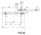
- any displacement on emission of ⁇ E in the appropriate direction, where ⁇ E is the separation between the transmitters, makes it possible to reduce the amplitude of the additional movement to be carried out by reception.
- the size of the sub-antenna is therefore extended by ⁇ E relative to the if the movement is made only at reception.
- This dual frequency auxiliary transmission mode is also usable for a frontal sonar.
- a synthetic mode of a lateral surveillance sonar is considered.
- this sonar makes it possible to operate at a maximum speed close to 10 knots with a resolution of around 20cm at the maximum range of 100m.
- One of these two transmitters transmits the main code and the two transmitters transmit the two auxiliary codes alternately.
- the bandwidth of the three transmissions is around 10 kHz.
- the minimum size of the isoplanetic zones is then of the order of 20 cm to 100 m.
Landscapes
- Engineering & Computer Science (AREA)
- Radar, Positioning & Navigation (AREA)
- Remote Sensing (AREA)
- Physics & Mathematics (AREA)
- Acoustics & Sound (AREA)
- Computer Networks & Wireless Communication (AREA)
- General Physics & Mathematics (AREA)
- Measurement Of Velocity Or Position Using Acoustic Or Ultrasonic Waves (AREA)
Description
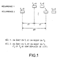
- la figure 1, une représentation d'un transducteur déplacé en réception utilisé par l'art antérieur;
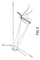
- la figure 2, une vue du fond de la mer obtenue à l'aide d'un sonar présentant un pilonnement vertical, permettant de mettre en évidence les limitations de l'art antérieur;
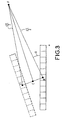
- la figure 3, une vue d'une antenne physique à l'émission et à la réception, permettant de définir les paramètres utilisés;
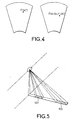
- la figure 4, deux images sonar successives obtenues avec l'antenne physique, permettant d'illustrer le déplacement dans l'image d'un écho de fond;
- la figure 5, une représentation des tranches temporelles sur lesquelles s'effectuent les intercorrelations permettant d'estimer les décalages;
- la figure 6, une représentation d'une sous-antenne déplacée en réception entre les récurrences n°1 et n°2, de la première voie pointée sur un écho de fond F, et d'une pluralité de deuxièmes voies permettant la recherche de F à la récurrence n°2;
- la figure 7, un schéma permettant d'illustrer les changements de coordonnées sonar entre l'antenne et la sous-antenne;
- la figure 8, une représentation des positions des centres de phase déplacés relatifs à l'invention et à l'art antérieur;
- la figure 9, une représentation du déplacement de la sous-antenne pour un sonar frontal et pour un écho de fond à bâbord; et
- la figure 10, une représentation de la sous-antenne dans le cas où le déplacement est effectué simultanément à l'émission et à la réception et où l'antenne physique se déplace de plus que U2 entre deux récurrences consécutives.
Claims (5)
- Procédé de recalage d'images sonar au moyen de sous-antennes, caractérisé en ce que l'on choisit sur deux récurrences successives n°1 et n°2, pour un point F déterminé par ses coordonnées dans l'image sonar à la récurrence n°1, deux portions égales de l'antenne physique situées aux extrémités opposées de celle-ci et formant deux sous-antennes, que l'on forme avec la première sous-antenne une première voie pointée sur F, et avec la deuxième sous-antenne une pluralité de deuxièmes voies réparties sur un secteur suffisamment large pour contenir F, et que l'on retient celle des deuxièmes voies qui maximise le pic d'intercorrélation entre la première voie et chacune des deuxièmes voies, ce qui détermine, conjointement avec les deux sous-antennes, les coordonnées de F dans l'image sonar à la récurrence n°2.
- Procédé selon la revendication 1, caractérisé en ce que l'on répète ces opérations pour les deux sens de déplacement et pour une pluralité de tailles de sous-antenne, pour retenir le sens et la taille qui maximise les dits maxima des pics d'intercorrélation.
- Procédé selon l'une quelconque des revendications 1 et 2, caractérisé en ce que l'on répète ces opérations pour une grille de points F de l'image sonar à la récurrence n°1, ce qui permet d'utiliser les grandeurs estimées pour un point voisin de F comme conditions initiales et de recaler l'ensemble des deux images entre les récurrences successives.
- Procédé selon l'une quelconque des revendications 1 à 3, caractérisé en ce que l'on fait une estimation conjointe pour tout un sous-ensemble de points de la grille, en introduisant un modèle paramétrique des variations des grandeurs recherchées sur le sous-ensemble.
- Procédé selon l'une quelconque des revendications 1 à 4, caractérisé en ce que l'on utilise en outre au moins un émetteur supplémentaire et au moins un code d'émission supplémentaire.
Applications Claiming Priority (3)
| Application Number | Priority Date | Filing Date | Title |
|---|---|---|---|
| FR9700487A FR2758629B1 (fr) | 1997-01-17 | 1997-01-17 | Procede de recalage d'images sonar au moyen de sous-antennes |
| FR9700487 | 1997-01-17 | ||
| PCT/FR1998/000050 WO1998032031A1 (fr) | 1997-01-17 | 1998-01-13 | Procede de recalage d'images sonar au moyen de sous-antennes |
Publications (2)
| Publication Number | Publication Date |
|---|---|
| EP0953157A1 EP0953157A1 (fr) | 1999-11-03 |
| EP0953157B1 true EP0953157B1 (fr) | 2001-04-18 |
Family
ID=9502717
Family Applications (1)
| Application Number | Title | Priority Date | Filing Date |
|---|---|---|---|
| EP98902065A Expired - Lifetime EP0953157B1 (fr) | 1997-01-17 | 1998-01-13 | Procede de recalage d'images sonar au moyen de sous-antennes |
Country Status (5)
| Country | Link |
|---|---|
| US (1) | US6240050B1 (fr) |
| EP (1) | EP0953157B1 (fr) |
| DE (1) | DE69800713T2 (fr) |
| FR (1) | FR2758629B1 (fr) |
| WO (1) | WO1998032031A1 (fr) |
Families Citing this family (3)
| Publication number | Priority date | Publication date | Assignee | Title |
|---|---|---|---|---|
| US6922494B1 (en) * | 1999-09-24 | 2005-07-26 | Eye Web, Inc. | Automated image scaling |
| FR2905766B1 (fr) * | 2006-09-08 | 2011-09-30 | Ixsea | Sonar a antenne deformable et procede associe de traitement du signal pour former une antenne synthetique |
| FR3025031A1 (fr) * | 2014-08-25 | 2016-02-26 | Eca Robotics | Procede et dispositif sonar de determination de la vitesse de deplacement d'un vehicule naval par rapport au fond marin |
Family Cites Families (2)
| Publication number | Priority date | Publication date | Assignee | Title |
|---|---|---|---|---|
| US4930111A (en) * | 1989-06-30 | 1990-05-29 | The United States Of America As Represented By The Secretary Of The Navy | Overlap correlator synthetic aperture processor |
| US4987563A (en) * | 1990-02-07 | 1991-01-22 | Westinghouse Electric Corp. | Synthetic aperture minimum redundancy sonar apparatus |
-
1997
- 1997-01-17 FR FR9700487A patent/FR2758629B1/fr not_active Expired - Fee Related
-
1998
- 1998-01-13 WO PCT/FR1998/000050 patent/WO1998032031A1/fr not_active Ceased
- 1998-01-13 US US09/341,662 patent/US6240050B1/en not_active Expired - Fee Related
- 1998-01-13 EP EP98902065A patent/EP0953157B1/fr not_active Expired - Lifetime
- 1998-01-13 DE DE69800713T patent/DE69800713T2/de not_active Expired - Fee Related
Also Published As
| Publication number | Publication date |
|---|---|
| FR2758629B1 (fr) | 1999-04-09 |
| DE69800713D1 (de) | 2001-05-23 |
| WO1998032031A1 (fr) | 1998-07-23 |
| EP0953157A1 (fr) | 1999-11-03 |
| US6240050B1 (en) | 2001-05-29 |
| DE69800713T2 (de) | 2001-11-22 |
| FR2758629A1 (fr) | 1998-07-24 |
Similar Documents
| Publication | Publication Date | Title |
|---|---|---|
| EP0070494B1 (fr) | Sonar sous-marin | |
| Hansen et al. | Signal processing for AUV based interferometric synthetic aperture sonar | |
| EP0944844B1 (fr) | Sonar lateral a antenne synthetique | |
| FR3058227A1 (fr) | Radar fmcw multifaisceaux, notamment pour automobile | |
| FR2940462A1 (fr) | Procede de localisation par estimation multi-voies des tdoa et fdoa des multi-trajets d'une source avec ou sans aoa | |
| EP0855079B1 (fr) | Procede d'autofocalisation pour sonar a antenne synthetique | |
| FR3054888A1 (fr) | Procede de mesure de la hauteur d'une cible par rapport au sol par un radar en mouvement, et radar mettant en oeuvre un tel procede | |
| CN105891836A (zh) | 一种基于测深侧扫声纳的二次回波抑制及地貌图融合方法 | |
| FR2998975A1 (fr) | Procede de filtrage, dans un signal radar, des ambiguites distance par codage d'impulsions et traitement multi-voies | |
| EP0953157A1 (fr) | Procede de recalage d'images sonar au moyen de sous-antennes | |
| FR2864249A1 (fr) | Systeme d'evitement d'obstacles pour navires multi-coques rapides | |
| CA2652564A1 (fr) | Sonar frontal ameliore | |
| CA2901647C (fr) | Procede et dispositif sonar de determination de la vitesse de deplacement d'un vehicle naval par rapport au fond marin | |
| EP1354218B1 (fr) | Antenne sonar synthetique interferometrique | |
| EP1204884B1 (fr) | Systeme de reperage acoustique par bouees sous-marines | |
| Pinto | Use of frequency and transmitter location diversities for ambiguity suppression in synthetic aperture sonar systems | |
| Shippey et al. | Position correction using echoes from a navigation fix for synthetic aperture sonar imaging | |
| EP0626073B1 (fr) | Procede de detection de cible sous-marine avec diversite de frequence | |
| Novella et al. | Low frequency SAS: Influence of multipaths on spatial coherence | |
| EP1522871B1 (fr) | Radar à formation de voies d'écartométrie synthétiques | |
| Bienvenu | Signal sonar processing | |
| EP3074783B1 (fr) | Systeme et procede de localisation d'emissions sonar interceptees | |
| EP0593532B1 (fr) | Systeme d'exploration des fonds marins | |
| Burlet | Platform motion estimation of a low frequency synthetic aperture sonar for buried objects detection | |
| EP2558881B1 (fr) | Traitement adaptatif de formation de voies pour sonar actif |
Legal Events
| Date | Code | Title | Description |
|---|---|---|---|
| PUAI | Public reference made under article 153(3) epc to a published international application that has entered the european phase |
Free format text: ORIGINAL CODE: 0009012 |
|
| 17P | Request for examination filed |
Effective date: 19990712 |
|
| AK | Designated contracting states |
Kind code of ref document: A1 Designated state(s): DE GB SE |
|
| GRAG | Despatch of communication of intention to grant |
Free format text: ORIGINAL CODE: EPIDOS AGRA |
|
| 17Q | First examination report despatched |
Effective date: 20000822 |
|
| GRAG | Despatch of communication of intention to grant |
Free format text: ORIGINAL CODE: EPIDOS AGRA |
|
| GRAH | Despatch of communication of intention to grant a patent |
Free format text: ORIGINAL CODE: EPIDOS IGRA |
|
| GRAH | Despatch of communication of intention to grant a patent |
Free format text: ORIGINAL CODE: EPIDOS IGRA |
|
| GRAA | (expected) grant |
Free format text: ORIGINAL CODE: 0009210 |
|
| AK | Designated contracting states |
Kind code of ref document: B1 Designated state(s): DE GB SE |
|
| REF | Corresponds to: |
Ref document number: 69800713 Country of ref document: DE Date of ref document: 20010523 |
|
| GBT | Gb: translation of ep patent filed (gb section 77(6)(a)/1977) |
Effective date: 20010713 |
|
| REG | Reference to a national code |
Ref country code: GB Ref legal event code: IF02 |
|
| PLBE | No opposition filed within time limit |
Free format text: ORIGINAL CODE: 0009261 |
|
| STAA | Information on the status of an ep patent application or granted ep patent |
Free format text: STATUS: NO OPPOSITION FILED WITHIN TIME LIMIT |
|
| 26N | No opposition filed | ||
| PGFP | Annual fee paid to national office [announced via postgrant information from national office to epo] |
Ref country code: SE Payment date: 20070104 Year of fee payment: 10 |
|
| PGFP | Annual fee paid to national office [announced via postgrant information from national office to epo] |
Ref country code: GB Payment date: 20070110 Year of fee payment: 10 |
|
| PGFP | Annual fee paid to national office [announced via postgrant information from national office to epo] |
Ref country code: DE Payment date: 20070111 Year of fee payment: 10 |
|
| EUG | Se: european patent has lapsed | ||
| GBPC | Gb: european patent ceased through non-payment of renewal fee |
Effective date: 20080113 |
|
| PG25 | Lapsed in a contracting state [announced via postgrant information from national office to epo] |
Ref country code: DE Free format text: LAPSE BECAUSE OF NON-PAYMENT OF DUE FEES Effective date: 20080801 |
|
| PG25 | Lapsed in a contracting state [announced via postgrant information from national office to epo] |
Ref country code: GB Free format text: LAPSE BECAUSE OF NON-PAYMENT OF DUE FEES Effective date: 20080113 |
|
| PG25 | Lapsed in a contracting state [announced via postgrant information from national office to epo] |
Ref country code: SE Free format text: LAPSE BECAUSE OF NON-PAYMENT OF DUE FEES Effective date: 20080114 |