EP0952264A2 - Drain cleaning apparatus - Google Patents
Drain cleaning apparatus Download PDFInfo
- Publication number
- EP0952264A2 EP0952264A2 EP99630032A EP99630032A EP0952264A2 EP 0952264 A2 EP0952264 A2 EP 0952264A2 EP 99630032 A EP99630032 A EP 99630032A EP 99630032 A EP99630032 A EP 99630032A EP 0952264 A2 EP0952264 A2 EP 0952264A2
- Authority
- EP
- European Patent Office
- Prior art keywords
- cable
- drum
- housing
- axis
- drain cleaning
- Prior art date
- Legal status (The legal status is an assumption and is not a legal conclusion. Google has not performed a legal analysis and makes no representation as to the accuracy of the status listed.)
- Granted
Links
Images


Classifications
-
- B—PERFORMING OPERATIONS; TRANSPORTING
- B08—CLEANING
- B08B—CLEANING IN GENERAL; PREVENTION OF FOULING IN GENERAL
- B08B9/00—Cleaning hollow articles by methods or apparatus specially adapted thereto
- B08B9/02—Cleaning pipes or tubes or systems of pipes or tubes
- B08B9/027—Cleaning the internal surfaces; Removal of blockages
- B08B9/04—Cleaning the internal surfaces; Removal of blockages using cleaning devices introduced into and moved along the pipes
- B08B9/043—Cleaning the internal surfaces; Removal of blockages using cleaning devices introduced into and moved along the pipes moved by externally powered mechanical linkage, e.g. pushed or drawn through the pipes
- B08B9/045—Cleaning the internal surfaces; Removal of blockages using cleaning devices introduced into and moved along the pipes moved by externally powered mechanical linkage, e.g. pushed or drawn through the pipes the cleaning devices being rotated while moved, e.g. flexible rotating shaft or "snake"
Definitions
- This invention relates to the art of drain cleaning apparatus and, more particularly, to improvements in connection with transmitting torque to the drain cleaning cable in such apparatus and directing and feeding the cable into a drain or waste line to be cleaned.
- Drain cleaning apparatus of the character to which the present invention is directed is generally comprised of a motor driven snake or drain cleaning cable drum in which the drain cleaning cable is wound about the axis of the drum and is rotatable therewith.
- the drum has an open front end through which a free or outer end of the cable extends for entrance into a drain to be cleaned and, in order to optimize the torque transmitted to the cable by rotation of the drum, cable guide tubes have been provided in the drum, or the inner end of the cable has been clamped to the drum.
- Guide tube arrangements are structurally complex and require somewhat complicated mountings in the drum, and cable clamps require mounting holes through the drum which leads to water leakage relative to the drum.
- the snake or drain cleaning cable in such apparatus is an elongate, flexible member made of tightly wound spring wire, and the free or outer end thereof is adapted to be pulled from or pushed back into the drum in which the cable is stored during periods of non-use.
- the drum, or a cable cartridge within the drum can be removed to facilitate connecting successive lengths of cable for feeding into a waste line, or for using different diameter drain cleaning cables with the apparatus.
- drain cleaners of the foregoing character not only require that the cable be manually pulled or pushed relative to the cable drum housing, but also require the operator to manually bend or flex the cable in order to direct it into the entrance of a drain or waste line to be cleaned.
- the torque transmitted from a cable storage drum or cartridge to a cable having its inner end detached from the drum is considerably increased over that heretofore obtainable.
- the inner end of a drain cleaning cable in a storage drum or cartridge is provided with an attachment which frictionally engages the inner surface of the storage container to resist slippage therebetween and thus increase the torque transmitted to the cable during operation of the apparatus.
- the outer or free end of a drain cleaning cable extends through a flexible guide tube which is provided on its outer end with a manually operable device for feeding the cable from and to the storage drum, thus to preclude an operator having to manually pull or push the cable relative to the drum.
- the flexibility of the guide tube advantageously enables the operator to direct the free end of the cable into a drain or waste line to be cleaned, whereby both the entrance of the cable into the drain opening and the advancement thereof during the cleaning operation can be achieved without the operator having to touch the cable.
- the drain cleaning apparatus is more convenient to use than apparatus heretofore available, and the cleaning operation is achieved more quickly and more efficiently than heretofore possible as a result of the flexible guide tube and cable feeding components.
- the flexible guide tube and cable feed device, or the cable feed device alone are selectively mountable on the apparatus for use with the drain cleaning cable thereof, thereby providing versatility with respect to the options available to an operator in connection with use of the apparatus.
- Another object is the provision of drain cleaning apparatus of the foregoing character in which the inner end of the drain cleaning cable coiled in the drum is detached therefrom and provided with an arrangement for frictionally interengaging with the drum in a manner to increase the transmission of torque to the cable relative to such apparatus heretofore available in which the inner end of the cable is detached from the drum.
- Still another object is the provision of apparatus of the foregoing character in which the outer or free end of the drain cleaning cable can be displaced relative to the storage drum and into the entrance of a drain or waste line to be cleaned without hand contact of the cable by the operator.
- a further object is the provision of drain cleaning apparatus of the foregoing character in which a manually operable drain cleaning cable feed device is selectively attachable to the apparatus alone or through the use of a flexible guide tube, thus promoting versatility with respect to use of the apparatus by an operator and enabling the extension and retraction of the cable relative to the storage drum and direction of the cable into the inlet end of a drain to be cleaned without hand contact of the cable by the operator.
- Yet another object is the provision of apparatus of the foregoing character which is more convenient to use than similar apparatus heretofore available and which is more efficient in connection with achieving a drain or waste line cleaning operation.
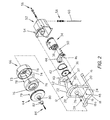
- Figures 1 and 2 illustrate drain cleaning apparatus 10 comprising a frame 12 which supports a cable drum assembly 14 for rotation about a cable drum axis A.
- Frame 12 comprises a tubular metal base portion having laterally spaced apart legs 16 interconnected at their forward ends by a U-shaped bridging portion 18 which inclines upwardly and forwardly relative to legs 16.
- the frame further includes an inverted U-shaped tubular metal frame member having laterally spaced apart legs 20 welded to and extending upwardly from legs 16 of the base portion of the frame and having a bridging portion 22 between the upper ends of the legs, and a mounting and support plate 24 which extends between and is welded or otherwise secured to legs 20.
- Cable drum assembly 14 is supported on plate 24 for rotation about axis A by a bearing support member 26 which is welded on plate 24, bearing sleeves 28 and 30 received in axially opposite ends of member 26, and a drum shaft 32 rotatably supported by the bearing sleeves and interconnected with the drum assembly as set forth hereinafter.
- Drum shaft 32 is adapted to be driven by a reversible motor 34 through a pulley and endless belt unit including a pulley 36 mounted on and driven by motor shaft 38, a pulley 40 mounted on the inner end of drum shaft 32 and interconnected therewith such as by a flat so as to rotate the drum shaft, and an endless belt 42 trained about pulleys 36 and 40.
- Motor 34 is attached to a motor mounting plate 44 by means of a plurality of button head screws 46, and mounting plate 44 is secured to mounting and support plate 24 of the frame by carriage bolts 48 and nuts 50.
- the drive motor, pulleys and drive belt are enclosed in a housing 52 which is attached to support plate 24 by a plurality of threaded fasteners 54, and housing 52 supports a toggle switch unit 56 for controlling motor 34 and a flexible protective sleeve 58 through which motor power cord 60 extends for connection to a source of AC current.
- frame 12 includes a handle 62 which extends rearwardly over housing 52 and by which the apparatus can be carried.
- Cable drum assembly 14 comprises front and rear cable drum housing members 64 and 66, respectively, and an intermediate cable cartridge 68 in which, as will be appreciated from Figure 3, a drain cleaning snake or cable 70 is coiled about axis A.
- Rear housing member 66 includes a hub 72 which is internally threaded on the inner or rear end thereof to interengage with threaded axially outer end 32a of drum shaft 32 so as to mount the cable drum assembly on shaft 32 for rotation therewith.
- Rear housing 66 is further secured to drum shaft 32 by a flat head screw 73 which extends through an opening therefor in hub 72 and into a threaded bore in end 32a of the drum shaft.
- Rear housing member 66 further includes radially inwardly extending ribs 74 which axially slidably interengage with recesses 76 in the outer periphery of cartridge 68 so as to engage the latter with housing member 66 for rotation therewith.
- Cartridge 68 is axially retained in rear housing member 66 by front housing member 64 which is secured to housing member 66 by a plurality of headed fasteners 78 in the outer ends of ribs 74 and drum clips 79 mounted on front housing member 64 and providing bayonet slots for fasteners 78.
- Front housing member 64 has a forwardly extending hub 80 to which an exit collar 82 is secured by means of a set screw, not designated numerically, and cable 70 extends through the hub and exit collar drum from cartridge 68 and has a free or outer end 84 for entry into a drain or waste line to be cleaned. Accordingly, it will be appreciated that the hub and exit collar provide an opening at the front of cable drum assembly 14 through which the free end of the drain cleaning cable extends for entry into a drain to be cleaned.
- cable drum cartridge 68 includes an outer peripheral wall 86, a closed inner or rear end defined by a peripheral wall 88 extending radially inwardly from wall 86 and an axially forwardly extending peripheral wall 90 spaced radially inwardly from outer wall 86 and terminating in a cone-shaped forward end wall 92, and a front end defined by a peripheral wall 94 extending radially inwardly from outer wall 86.
- the radially inner end of wall 94 is spaced radially outwardly from cone-shaped wall 92 and provides a peripheral opening 96 therewith through which cable 70 extends for passage through hub 80 and exit collar 82 of the drum assembly.
- cable 70 is wound in the cartridge about axis A between the front and rear ends of the cartridge and, as a result of the bias of the spring metal from which the cable is constructed, is biased radially outwardly against wall 86 of the cartridge.
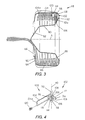
- cable 70 has an inner end 98 disposed adjacent the juncture between outer wall 86 and rear wall 88 of the cartridge incasing and provided with a torque arm 100 which operates as set forth hereinafter to increase the torque applied to cable 70 in response to rotation of the drum assembly during operation of the drain cleaning apparatus.
- torque arm 100 is constructed from a strip of cold rolled steel and has a mounting end 102 by which the torque arm is attached to end 98 of the cable.
- the torque arm comprises an elongate, planar first leg 104 extending from mounting end 102, and the latter is defined by a pair of second legs 106 each of which is parallel to leg 104 and integrally interconnected therewith by a corresponding U-shaped bridging portion 108.
- Bridging portions 108 provide mounting end 102 of the torque arm with an axis 110 with respect to which legs 106 are spaced apart from one another and, preferably, the torque arm further includes a finger 112 axially between legs 106 and bridging portions 108 and which is integral with first leg 104 and extends perpendicular thereto and tangential to bridging portions 108.
- a nut or other block member 114 extends between first leg 104 and the free ends of second legs 106 and is securely fastened thereto such as by weldments 116.
- Block 114 is provided with a threaded opening 118 therethrough extending radially of axis 110 for receiving a threaded fastener 120, such as a set screw, by which the torque arm is removably mounted on end 98 of the drain cleaning cable.
- a threaded fastener 120 such as a set screw
- leg 104 of the torque arm is adjacent outer wall 86 of the cartridge housing and extends from the juncture between outer wall 86 and rear wall 88 to a point adjacent the juncture between the outer wall and front wall 94.
- the torque arm is biased radially outwardly by the resiliency and coiled condition of cable 70 in the cartridge housing and frictionally engages outer wall 86 along the length of leg 104 to front edge 104a thereof and into the bridging portions 108 at mounting end 102 of the torque arm.
- Finger 112 extends radially inwardly from mounting end 102 and engages rear wall 88 of the cartridge housing along upper or radially inner edge 112a of the finger.
- torque arm 100 resists sliding of cable 70 relative to the cartridge housing when an obstruction or the like is encountered by the leading end of the snake which is disposed in the drain or waste line being cleaned. While finger 112 contributes to the resistance to sliding, its primary purpose is to stabilize the torque against pivotal movement clockwise in Figure 3 about axis 110 when the radially outward bias on leg 104 by the cable is reduced, such as when the cable is nearly fully extended from the cartridge housing.
- the cold rolled steel strip of which the torque arm is constructed has a thickness of 0.06 inch, a width of 0.75 inch and a length of 2.50 inches from axis 110 to edge 104a of leg 104.
- the curvature of bridging portions 106 has a radius of 0.22 inch with respect to axis 110
- finger 112 has a length of 0.69 inch from axis 110 to edge 112a of the finger.
- Each of the legs 106 and finger 112 have a width of 0.25 inch in the direction of axis 110.
- U-shaped portion 18 of the base of frame 12 includes a portion 18a extending horizontally across the front end of drum assembly 14 below exit collar 82 thereof, and a manually operable cable feed device 122 is mounted on frame portion 18a by means of a mounting bracket 124 to facilitate the selective feeding of drain cleaning cable 70 outwardly and inwardly relative to drum assembly 14.
- Cable feed device 122 corresponds structurally and functionally to the cable feed device disclosed in co-pending patent application Serial No. 901,653 filed July 28, 1997 in the names of Michael J. Rutkowski and Jon R. Dunkin and assigned to the same assignee as the present application.
- cable feed device 122 comprises a tubular housing 126 having an axis coinciding with axis A of the apparatus and axially opposite front and rear ends 128 and 130, respectively.
- Housing 126 includes a wall 132 therein transverse to axis A and having a passage 134 for receiving cable 70.
- Wall 132 includes roll mounting nodes 136 on the front side thereof, and the feed device includes a pair of cable driving rolls 138 and 140 mounted on nodes 136 by socket head cap screws 142 and 144, respectively.
- the cap screws provide axes for rotation of the respective driving rolls, and each driving roll axis is skewed both horizontally and vertically relative to the housing axis.
- Driving rolls 138 and 140 have smooth outer surfaces 146 and 148, respectively, and the skewed mounting thereof provides for driving drain cleaning cable 7G in a well known manner when the cable is rotated and displaced against the driving rolls.
- Housing 126 further includes a radially extending bore 150 having an inner end which opens into cable passage 134 and which slidably and removably receives a cable drive actuating unit including a drive actuating roll support member 152.
- Support member 152 has a radially inner end on which a drive actuating roll 154 is mounted by means of a socket head cap screw 156 which provides an axis for the drive actuating roll, and an axially outer end on which an operating knob member 158 is mounted by way of a threaded stem 160 received in a threaded recess therefor in roll support member 152, not designated numerically.
- Operating knob member 158 is axially adjustable relative to roll support member 152 for adjusting the axial length of the drive actuating unit, and a compression spring 162 surrounds the roll support member between the radially outer end of bore 150 and the underside of operating knob member 158 to bias the drive actuating unit radially outwardly of the housing.
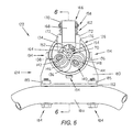
- Drive actuating roll 154 has a smooth outer surface 164 and, as will be appreciated from Figure 5, the driving rolls and actuator drive roll are equally spaced apart circumferentially about axis A. Further, drive actuating roll support member 152 supports drive actuating roll 154 in housing 12 for the axis of the drive actuating roll to be skewed horizontally with respect to axis A, preferably at the same angle as that of driving rolls 138 and 140 which, preferably, is 30° with respect to both the horizontal and vertical directions of the skew thereof.
- the drive actuating unit of feed device 122 is adapted to be displaced radially inwardly of housing 126 against the bias of spring 162 by means of an operating lever 166 which includes a mounting leg 168 and a handle portion 170 extending perpendicular thereto.
- the front end of housing 126 is provided with a pair of lever mounting ears 172, and mounting leg 168 of the lever is received between ears 172 and has a rolled tubular lower end 174 receiving a pivot pin 176 extending through openings therefor in ears 172 to provide a lever pivot axis transverse to and laterally spaced from axis A.
- Handle portion 170 extends across the outer surface of operating knob member 158 and is provided with a finger 178 which frictionally engages with the peripheral outer surface of the knob member to releasably hold the drive actuating unit in bore 150 and to restrain rotation of the operating knob member relative to drive actuating roll support member 152.
- mounting bracket 124 includes an L-shaped bracket plate having a vertical leg 180 and a horizontal leg 182 extending forwardly from the lower end thereof and secured to frame portion 18a such as by a pair of bolts 184 extending upwardly through openings therefor in frame portion 18a and into threaded engagement with nuts 185 welded on leg 182 of the bracket plate.
- Leg 180 is provided with an opening 186 coaxial with axis A, and the mounting bracket further includes an annular adaptor sleeve 188 mounted on the front side of leg 180 such as by welding and so as to be coaxial with axis A.
- Inner end 130 of housing 126 of the cable feed device axially receives adaptor sleeve 188 therein, and the housing is provided with diametrically opposed pairs of openings 190 adapted to be aligned with corresponding bores 192 in the radially outer side of adaptor sleeve 188. Openings 190 are internally threaded to receive the threaded shanks of bolts 194 by which housing 126 and thus feed device 122 is removably mountable on the drain cleaning apparatus.
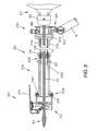
- drain cleaning cable feed device 122 is mounted on the outer end of a flexible guide tube assembly 196 having its inner end detachably connected to adaptor 188 of mounting bracket 124. More particularly, guide tube 196 comprises a flexible hose 198 having coupling arrangements 200 and 202 on the opposite ends of the hose and which respectively provide the axially outer and axially inner ends of the flexible guide tube.
- Coupling arrangement 200 comprises a ferrule axially received on the outer end of hose 198 and including an inner sleeve 206 extending axially inwardly of the hose, and a connector member 208 having a central flange 209, a recess 210 on one side thereof receiving ferrule 204, and an externally threaded sleeve 212 on the other side thereof.
- Coupling arrangement 200 further includes a gland ring 214 and a compression nut 216 by which ferrule 204 and thus the corresponding end of hose 198 is attached to connector member 208, and a tubular mounting collar 218 which is internally threaded at one end for threaded interengagement with externally threaded sleeve 212 of connector member 208.
- Mounting collar 218 is axially received in inner end 130 of housing 126 of the cable feed device and is provided with an outwardly open annular recess 220 which is adapted to receive the inner ends of fasteners 194 provided on housing 126 in diametrically opposed pairs.
- the inner ends of fasteners 194 and recess 220 are dimensioned for the fasteners to slide circumferentially in the recess, whereby an operator can rotate cable feed device 122 about the axis of the flexible guide tube.
- Coupling arrangement 202 comprises a mounting collar having an axially outer end 224 for receiving adaptor 188 of mounting bracket 124 and having an axially inner end which is necked in to provide a cradle 226 underlying the corresponding end of hose 198.
- a hose clamp 228 and fasteners 229 secure hose 198 to cradle 226 and thus the mounting collar.
- Collar 224 supports a spring biased mounting plunger 230 which includes a post 232 extending radially through an opening therefor in collar 224 and into one of the bores 192 in adaptor 188.
- the plunger includes an operating member 234 on the radially outer end of post 232, and a spring unit 236 normally biases post 232 radially inwardly of bore 192. Accordingly, it will be appreciated that the guide tube and cable feed device can readily be detached from the drain cleaning apparatus by pulling outwardly on operating member 234 to withdraw post 232 from bore 192 so as to free the mounting collar 224 for axial separation from adaptor 188.
- drain cleaning cable 70 is adapted to extend through the flexible hose and coupling arrangements and outwardly through feed device 122 which is operable in the manner described hereinabove to displace the cable axially in response to rotation of the cable drum assembly.
- Hose 198 can be of any desired length and, preferably, has a length of about three feet which advantageously enables the operator to hold feed device 122 in one hand and to flex the guide tube as is necessary to direct outer end 84 of the cable into a drain or waste line to be cleaned. Accordingly, the operator can perform a drain cleaning operation without having to physically touch the drain cleaning cable.
- Figure 9 illustrates a modification of the flexible guide tube shown in Figures 7 and 8 and, in this respect, illustrates a hand grip component 238 which replaces mounting collar 218 of the guide tube assembly shown in the latter figures.
- Hand grip 238 is a tubular metal member having an axial length and outer diameter to accommodate an operator's hand and is provided at one of the opposite ends thereof with internal threads 240 for threaded interengagement with externally threaded collar 212 of connector member 208.
- the other end of the hand grip is provided with a radially outwardly open circumferential recess 242 which receives and cooperates with fasteners 194 on the feed device housing to support the feed device for rotation about the axis of the guide tube as described hereinabove in connection with the embodiment of Figures 7 and 8.
- the flexible guide tube can be used with drain cleaning apparatus independent of a torque arm on the inner end of the drain cleaning cable in the cable drum.
- a torque arm according to the invention can be used in conjunction with the detached end of a cable wound in a cable drum per se as opposed to a cartridge removably mounted in a drum housing.
Abstract
Description
- This invention relates to the art of drain cleaning apparatus and, more particularly, to improvements in connection with transmitting torque to the drain cleaning cable in such apparatus and directing and feeding the cable into a drain or waste line to be cleaned.
- Drain cleaning apparatus of the character to which the present invention is directed is generally comprised of a motor driven snake or drain cleaning cable drum in which the drain cleaning cable is wound about the axis of the drum and is rotatable therewith. The drum has an open front end through which a free or outer end of the cable extends for entrance into a drain to be cleaned and, in order to optimize the torque transmitted to the cable by rotation of the drum, cable guide tubes have been provided in the drum, or the inner end of the cable has been clamped to the drum. Guide tube arrangements are structurally complex and require somewhat complicated mountings in the drum, and cable clamps require mounting holes through the drum which leads to water leakage relative to the drum. While it is preferred to avoid the foregoing problems by eliminating the guide tube or not attaching the inner end of the cable to the drum, the result is that the slippage between the cable and drum restricts the transmission of torque to the cable by the drum and thus restricts the magnitude of a blockage which can be broken up or cleared with the apparatus.
- The snake or drain cleaning cable in such apparatus, as is conventional, is an elongate, flexible member made of tightly wound spring wire, and the free or outer end thereof is adapted to be pulled from or pushed back into the drum in which the cable is stored during periods of non-use. In many such apparatus, the drum, or a cable cartridge within the drum, can be removed to facilitate connecting successive lengths of cable for feeding into a waste line, or for using different diameter drain cleaning cables with the apparatus. Often, drain cleaners of the foregoing character not only require that the cable be manually pulled or pushed relative to the cable drum housing, but also require the operator to manually bend or flex the cable in order to direct it into the entrance of a drain or waste line to be cleaned. Even though an operator may wear gloves, whereby his or her hands are protected from dirt and/or abrasive contact with the drain cleaning cable, such protection is not obtained in the absence of gloves and, in any event, pulling, pushing and flexing the cable into position is inconvenient for the operator.
- In accordance with the present invention, improvements are provided by which the foregoing and other problems encountered with motor driven drain cleaning apparatus arc minimized or overcome. In accordance with one aspect of the invention, the torque transmitted from a cable storage drum or cartridge to a cable having its inner end detached from the drum is considerably increased over that heretofore obtainable. In this respect, the inner end of a drain cleaning cable in a storage drum or cartridge is provided with an attachment which frictionally engages the inner surface of the storage container to resist slippage therebetween and thus increase the torque transmitted to the cable during operation of the apparatus.
- In accordance with another aspect of the invention, the outer or free end of a drain cleaning cable extends through a flexible guide tube which is provided on its outer end with a manually operable device for feeding the cable from and to the storage drum, thus to preclude an operator having to manually pull or push the cable relative to the drum. Moreover, the flexibility of the guide tube advantageously enables the operator to direct the free end of the cable into a drain or waste line to be cleaned, whereby both the entrance of the cable into the drain opening and the advancement thereof during the cleaning operation can be achieved without the operator having to touch the cable. Accordingly, the drain cleaning apparatus is more convenient to use than apparatus heretofore available, and the cleaning operation is achieved more quickly and more efficiently than heretofore possible as a result of the flexible guide tube and cable feeding components. Preferably, the flexible guide tube and cable feed device, or the cable feed device alone, are selectively mountable on the apparatus for use with the drain cleaning cable thereof, thereby providing versatility with respect to the options available to an operator in connection with use of the apparatus.
- It is accordingly an outstanding object of the present invention to provide improvements in connection with drain cleaning apparatus of the character comprising a motor driven storage drum in which a drain cleaning cable is coiled about the axis of the drum and has a free or outer end extending outwardly of the drum for entry into a drain or waste line to be cleaned.
- Another object is the provision of drain cleaning apparatus of the foregoing character in which the inner end of the drain cleaning cable coiled in the drum is detached therefrom and provided with an arrangement for frictionally interengaging with the drum in a manner to increase the transmission of torque to the cable relative to such apparatus heretofore available in which the inner end of the cable is detached from the drum.
- Still another object is the provision of apparatus of the foregoing character in which the outer or free end of the drain cleaning cable can be displaced relative to the storage drum and into the entrance of a drain or waste line to be cleaned without hand contact of the cable by the operator.
- A further object is the provision of drain cleaning apparatus of the foregoing character in which a manually operable drain cleaning cable feed device is selectively attachable to the apparatus alone or through the use of a flexible guide tube, thus promoting versatility with respect to use of the apparatus by an operator and enabling the extension and retraction of the cable relative to the storage drum and direction of the cable into the inlet end of a drain to be cleaned without hand contact of the cable by the operator.
- Yet another object is the provision of apparatus of the foregoing character which is more convenient to use than similar apparatus heretofore available and which is more efficient in connection with achieving a drain or waste line cleaning operation.
- The foregoing objects, and others, will in part be obvious, and in part pointed out more fully hereinafter in conjunction with the written description of preferred embodiments of the invention illustrated in the accompanying drawings in which:
- FIGURE 1 is a perspective view of drain cleaning apparatus in accordance with the present invention;
- FIGURE 2 is an exploded perspective view of the apparatus shown in Figure 1;
- FIGURE 3 is a sectional elevation view through the cable cartridge component of the drum assembly and showing a torque arm on the inner end of the cable in accordance with the invention;
- FIGURE 4 is a perspective view of the torque arm illustrated in Figure 3;
- FIGURE 5 is an end elevation view showing a manually operable cable feed device mounted on a frame component of the apparatus illustrated in Figure 1;
- FIGURE 6 is a sectional elevation view of the cable feed device taken along lines 6-6 in Figure 5;
- FIGURE 7 is a perspective view of one embodiment of a flexible guide tube and cable feed attachment for the drain cleaning apparatus;
- FIGURE 8 is a sectional elevation view of the attachment in Figure 7; and,
- FIGURE 9 is a sectional elevation view showing a modification of the flexible guide tube attachment.
- Referring now in greater detail to the drawings, wherein the showings are for the purpose of illustrating preferred embodiments of the invention only and not for the purpose of limiting the invention, Figures 1 and 2 illustrate drain cleaning apparatus 10 comprising a
frame 12 which supports acable drum assembly 14 for rotation about a cable drumaxis A. Frame 12 comprises a tubular metal base portion having laterally spaced apartlegs 16 interconnected at their forward ends by aU-shaped bridging portion 18 which inclines upwardly and forwardly relative tolegs 16. The frame further includes an inverted U-shaped tubular metal frame member having laterally spaced apartlegs 20 welded to and extending upwardly fromlegs 16 of the base portion of the frame and having abridging portion 22 between the upper ends of the legs, and a mounting andsupport plate 24 which extends between and is welded or otherwise secured tolegs 20.Cable drum assembly 14 is supported onplate 24 for rotation about axis A by abearing support member 26 which is welded onplate 24, bearingsleeves member 26, and adrum shaft 32 rotatably supported by the bearing sleeves and interconnected with the drum assembly as set forth hereinafter.Drum shaft 32 is adapted to be driven by areversible motor 34 through a pulley and endless belt unit including apulley 36 mounted on and driven bymotor shaft 38, apulley 40 mounted on the inner end ofdrum shaft 32 and interconnected therewith such as by a flat so as to rotate the drum shaft, and anendless belt 42 trained aboutpulleys Motor 34 is attached to amotor mounting plate 44 by means of a plurality ofbutton head screws 46, andmounting plate 44 is secured to mounting and supportplate 24 of the frame bycarriage bolts 48 andnuts 50. The drive motor, pulleys and drive belt are enclosed in ahousing 52 which is attached to supportplate 24 by a plurality of threadedfasteners 54, andhousing 52 supports atoggle switch unit 56 for controllingmotor 34 and a flexibleprotective sleeve 58 through whichmotor power cord 60 extends for connection to a source of AC current. Preferably,frame 12 includes ahandle 62 which extends rearwardly overhousing 52 and by which the apparatus can be carried. -
Cable drum assembly 14 comprises front and rear cabledrum housing members intermediate cable cartridge 68 in which, as will be appreciated from Figure 3, a drain cleaning snake orcable 70 is coiled about axis A. Rearhousing member 66 includes ahub 72 which is internally threaded on the inner or rear end thereof to interengage with threaded axially outer end 32a ofdrum shaft 32 so as to mount the cable drum assembly onshaft 32 for rotation therewith.Rear housing 66 is further secured todrum shaft 32 by aflat head screw 73 which extends through an opening therefor inhub 72 and into a threaded bore in end 32a of the drum shaft.Rear housing member 66 further includes radially inwardly extendingribs 74 which axially slidably interengage withrecesses 76 in the outer periphery ofcartridge 68 so as to engage the latter withhousing member 66 for rotation therewith. Cartridge 68 is axially retained inrear housing member 66 byfront housing member 64 which is secured tohousing member 66 by a plurality of headedfasteners 78 in the outer ends ofribs 74 anddrum clips 79 mounted onfront housing member 64 and providing bayonet slots forfasteners 78.Front housing member 64 has a forwardly extendinghub 80 to which anexit collar 82 is secured by means of a set screw, not designated numerically, andcable 70 extends through the hub and exit collar drum fromcartridge 68 and has a free orouter end 84 for entry into a drain or waste line to be cleaned. Accordingly, it will be appreciated that the hub and exit collar provide an opening at the front ofcable drum assembly 14 through which the free end of the drain cleaning cable extends for entry into a drain to be cleaned. - In the embodiment illustrated in the drawings, and as best seen in Figure 3,
cable drum cartridge 68 includes an outerperipheral wall 86, a closed inner or rear end defined by aperipheral wall 88 extending radially inwardly fromwall 86 and an axially forwardly extendingperipheral wall 90 spaced radially inwardly fromouter wall 86 and terminating in a cone-shapedforward end wall 92, and a front end defined by aperipheral wall 94 extending radially inwardly fromouter wall 86. The radially inner end ofwall 94 is spaced radially outwardly from cone-shaped wall 92 and provides a peripheral opening 96 therewith through whichcable 70 extends for passage throughhub 80 andexit collar 82 of the drum assembly. As will be further appreciated from Figure 3,cable 70 is wound in the cartridge about axis A between the front and rear ends of the cartridge and, as a result of the bias of the spring metal from which the cable is constructed, is biased radially outwardly againstwall 86 of the cartridge. - In accordance with one aspect of the present invention, and as best seen in Figures 3 and 4 of the drawing,
cable 70 has aninner end 98 disposed adjacent the juncture betweenouter wall 86 andrear wall 88 of the cartridge incasing and provided with atorque arm 100 which operates as set forth hereinafter to increase the torque applied tocable 70 in response to rotation of the drum assembly during operation of the drain cleaning apparatus. In the embodiment illustrated,torque arm 100 is constructed from a strip of cold rolled steel and has a mountingend 102 by which the torque arm is attached toend 98 of the cable. More particularly, the torque arm comprises an elongate, planarfirst leg 104 extending from mountingend 102, and the latter is defined by a pair ofsecond legs 106 each of which is parallel toleg 104 and integrally interconnected therewith by a correspondingU-shaped bridging portion 108. Bridgingportions 108 provide mountingend 102 of the torque arm with anaxis 110 with respect to whichlegs 106 are spaced apart from one another and, preferably, the torque arm further includes afinger 112 axially betweenlegs 106 and bridgingportions 108 and which is integral withfirst leg 104 and extends perpendicular thereto and tangential to bridgingportions 108. A nut orother block member 114 extends betweenfirst leg 104 and the free ends ofsecond legs 106 and is securely fastened thereto such as byweldments 116.Block 114 is provided with a threadedopening 118 therethrough extending radially ofaxis 110 for receiving a threadedfastener 120, such as a set screw, by which the torque arm is removably mounted onend 98 of the drain cleaning cable. It will be appreciated thatlegs 106, bridgingportions 108 andblock 114 define a collar on mountingend 102 of the torque arm which snugly receives and surroundsend 98 of the cable and providesaxis 110. - As will be appreciated from Figure 3,
leg 104 of the torque arm is adjacentouter wall 86 of the cartridge housing and extends from the juncture betweenouter wall 86 andrear wall 88 to a point adjacent the juncture between the outer wall andfront wall 94. The torque arm is biased radially outwardly by the resiliency and coiled condition ofcable 70 in the cartridge housing and frictionally engagesouter wall 86 along the length ofleg 104 tofront edge 104a thereof and into the bridgingportions 108 at mountingend 102 of the torque arm.Finger 112 extends radially inwardly from mountingend 102 and engagesrear wall 88 of the cartridge housing along upper or radiallyinner edge 112a of the finger. Accordingly, it will be appreciated that in response to rotation of the cable drum assembly and thus cartridge housing 68 in connection with a drain cleaning operation,torque arm 100 resists sliding ofcable 70 relative to the cartridge housing when an obstruction or the like is encountered by the leading end of the snake which is disposed in the drain or waste line being cleaned. Whilefinger 112 contributes to the resistance to sliding, its primary purpose is to stabilize the torque against pivotal movement clockwise in Figure 3 aboutaxis 110 when the radially outward bias onleg 104 by the cable is reduced, such as when the cable is nearly fully extended from the cartridge housing. - In the embodiment illustrated, the cold rolled steel strip of which the torque arm is constructed has a thickness of 0.06 inch, a width of 0.75 inch and a length of 2.50 inches from
axis 110 toedge 104a ofleg 104. Further, the curvature ofbridging portions 106 has a radius of 0.22 inch with respect toaxis 110, andfinger 112 has a length of 0.69 inch fromaxis 110 toedge 112a of the finger. Each of thelegs 106 andfinger 112 have a width of 0.25 inch in the direction ofaxis 110. In a cable drum having the structure described hereinabove and in which the inner end of the drain cleaning cable corresponding to end 98 is not attached to the cartridge housing and does not have a torque arm attached thereto, slippage between the drain cleaning cable and cartridge housing with the free end of the cable held against rotationadjacent exit collar 82 occurs at a torque of between 5 and 10 in.-lbs. In comparison, with a torque arm of the foregoing structure attached to the inner end of the cable, slippage does not occur until a torque of about 35 in.-lbs. is applied to the cable by a cartridge housing. - In accordance with another aspect of the invention, as shown in Figures 5 and 6 of the drawing,
U-shaped portion 18 of the base offrame 12 includes aportion 18a extending horizontally across the front end ofdrum assembly 14 belowexit collar 82 thereof, and a manually operablecable feed device 122 is mounted onframe portion 18a by means of a mountingbracket 124 to facilitate the selective feeding ofdrain cleaning cable 70 outwardly and inwardly relative to drumassembly 14.Cable feed device 122 corresponds structurally and functionally to the cable feed device disclosed in co-pending patent application Serial No. 901,653 filed July 28, 1997 in the names of Michael J. Rutkowski and Jon R. Dunkin and assigned to the same assignee as the present application. Whilecable feed device 122 will be described herein in considerable detail, the foregoing co-pending application is hereby incorporated herein by reference and can be referred to for further structural detail. Figures 5 and 6 in the present application correspond respectively to Figures 2 and 4 in the foregoing co-pending application. - As shown in Figures 5 and 6,
cable feed device 122 comprises atubular housing 126 having an axis coinciding with axis A of the apparatus and axially opposite front andrear ends Housing 126 includes awall 132 therein transverse to axis A and having apassage 134 for receivingcable 70.Wall 132 includesroll mounting nodes 136 on the front side thereof, and the feed device includes a pair of cable driving rolls 138 and 140 mounted onnodes 136 by sockethead cap screws outer surfaces Housing 126 further includes aradially extending bore 150 having an inner end which opens intocable passage 134 and which slidably and removably receives a cable drive actuating unit including a drive actuatingroll support member 152.Support member 152 has a radially inner end on which adrive actuating roll 154 is mounted by means of a sockethead cap screw 156 which provides an axis for the drive actuating roll, and an axially outer end on which anoperating knob member 158 is mounted by way of a threadedstem 160 received in a threaded recess therefor inroll support member 152, not designated numerically. Operatingknob member 158 is axially adjustable relative to rollsupport member 152 for adjusting the axial length of the drive actuating unit, and acompression spring 162 surrounds the roll support member between the radially outer end ofbore 150 and the underside of operatingknob member 158 to bias the drive actuating unit radially outwardly of the housing. Drive actuatingroll 154 has a smoothouter surface 164 and, as will be appreciated from Figure 5, the driving rolls and actuator drive roll are equally spaced apart circumferentially about axis A. Further, drive actuatingroll support member 152 supports drive actuatingroll 154 inhousing 12 for the axis of the drive actuating roll to be skewed horizontally with respect to axis A, preferably at the same angle as that of drivingrolls - The drive actuating unit of
feed device 122 is adapted to be displaced radially inwardly ofhousing 126 against the bias ofspring 162 by means of an operatinglever 166 which includes a mountingleg 168 and ahandle portion 170 extending perpendicular thereto. The front end ofhousing 126 is provided with a pair oflever mounting ears 172, and mountingleg 168 of the lever is received betweenears 172 and has a rolled tubularlower end 174 receiving apivot pin 176 extending through openings therefor inears 172 to provide a lever pivot axis transverse to and laterally spaced from axisA. Handle portion 170 extends across the outer surface of operatingknob member 158 and is provided with afinger 178 which frictionally engages with the peripheral outer surface of the knob member to releasably hold the drive actuating unit inbore 150 and to restrain rotation of the operating knob member relative to drive actuatingroll support member 152. - As mentioned above,
cable feed device 122 is adapted to be mounted onframe portion 18a by means of a mountingbracket 124. As seen in Figures 5 and 6, mountingbracket 124 includes an L-shaped bracket plate having avertical leg 180 and ahorizontal leg 182 extending forwardly from the lower end thereof and secured to frameportion 18a such as by a pair ofbolts 184 extending upwardly through openings therefor inframe portion 18a and into threaded engagement withnuts 185 welded onleg 182 of the bracket plate.Leg 180 is provided with anopening 186 coaxial with axis A, and the mounting bracket further includes anannular adaptor sleeve 188 mounted on the front side ofleg 180 such as by welding and so as to be coaxial with axis A.Inner end 130 ofhousing 126 of the cable feed device axially receivesadaptor sleeve 188 therein, and the housing is provided with diametrically opposed pairs ofopenings 190 adapted to be aligned withcorresponding bores 192 in the radially outer side ofadaptor sleeve 188.Openings 190 are internally threaded to receive the threaded shanks ofbolts 194 by whichhousing 126 and thus feeddevice 122 is removably mountable on the drain cleaning apparatus. - In operation of the feed device, the component parts thereof are initially in the positions shown in Figure 6, whereby
cable 70 rotates relative tohousing 126 in response to rotation of the cable drum assembly. There is no axial displacement of the cable at this time in thatactuating drive roll 154 is disengaged from the cable. When handle 170 oflever 166 is displaced clockwise from the position shown in Figure 6, driveactuator roll 154 is displaced radially inwardly againstcable 70 to displace the latter against drive rolls 138 and 140 as shown in Figure 5. As a result of the skewed disposition of the rolls, they interengage with the rotating cable to cause the latter to advance axially ofhousing 126 in the direction relative to the housing which depends on the direction of rotation of the cable. In this respect, rotation of the cable in one direction advances the latter axially outwardly fromfront end 128 of the housing while rotation of the cable in the opposite direction draws the cable axially inwardly of the housing. When it is desired to stop axial displacement of the cable in either direction, handle 170 is released forspring 162 to return the drive actuating unit to the position thereof shown in Figure 6 and in which roll 152 disengages the cable. - In accordance with yet another aspect of the invention, as shown in Figures 7 and 8 of the drawing, drain cleaning
cable feed device 122 is mounted on the outer end of a flexibleguide tube assembly 196 having its inner end detachably connected toadaptor 188 of mountingbracket 124. More particularly, guidetube 196 comprises aflexible hose 198 havingcoupling arrangements arrangement 200 comprises a ferrule axially received on the outer end ofhose 198 and including aninner sleeve 206 extending axially inwardly of the hose, and aconnector member 208 having acentral flange 209, arecess 210 on one side thereof receivingferrule 204, and an externally threadedsleeve 212 on the other side thereof. Couplingarrangement 200 further includes agland ring 214 and acompression nut 216 by whichferrule 204 and thus the corresponding end ofhose 198 is attached toconnector member 208, and a tubular mounting collar 218 which is internally threaded at one end for threaded interengagement with externally threadedsleeve 212 ofconnector member 208. Mounting collar 218 is axially received ininner end 130 ofhousing 126 of the cable feed device and is provided with an outwardly open annular recess 220 which is adapted to receive the inner ends offasteners 194 provided onhousing 126 in diametrically opposed pairs. The inner ends offasteners 194 and recess 220 are dimensioned for the fasteners to slide circumferentially in the recess, whereby an operator can rotatecable feed device 122 about the axis of the flexible guide tube. - Coupling
arrangement 202 comprises a mounting collar having an axiallyouter end 224 for receivingadaptor 188 of mountingbracket 124 and having an axially inner end which is necked in to provide acradle 226 underlying the corresponding end ofhose 198. Ahose clamp 228 andfasteners 229secure hose 198 to cradle 226 and thus the mounting collar.Collar 224 supports a spring biased mountingplunger 230 which includes apost 232 extending radially through an opening therefor incollar 224 and into one of thebores 192 inadaptor 188. The plunger includes an operatingmember 234 on the radially outer end ofpost 232, and aspring unit 236 normally biases post 232 radially inwardly ofbore 192. Accordingly, it will be appreciated that the guide tube and cable feed device can readily be detached from the drain cleaning apparatus by pulling outwardly on operatingmember 234 to withdrawpost 232 frombore 192 so as to free the mountingcollar 224 for axial separation fromadaptor 188. As will be appreciated from Figure 8, when the guide tube is mounted on the drain cleaning apparatus, drain cleaningcable 70 is adapted to extend through the flexible hose and coupling arrangements and outwardly throughfeed device 122 which is operable in the manner described hereinabove to displace the cable axially in response to rotation of the cable drum assembly.Hose 198 can be of any desired length and, preferably, has a length of about three feet which advantageously enables the operator to holdfeed device 122 in one hand and to flex the guide tube as is necessary to directouter end 84 of the cable into a drain or waste line to be cleaned. Accordingly, the operator can perform a drain cleaning operation without having to physically touch the drain cleaning cable. - Figure 9 illustrates a modification of the flexible guide tube shown in Figures 7 and 8 and, in this respect, illustrates a
hand grip component 238 which replaces mounting collar 218 of the guide tube assembly shown in the latter figures.Hand grip 238 is a tubular metal member having an axial length and outer diameter to accommodate an operator's hand and is provided at one of the opposite ends thereof withinternal threads 240 for threaded interengagement with externally threadedcollar 212 ofconnector member 208. The other end of the hand grip is provided with a radially outwardly opencircumferential recess 242 which receives and cooperates withfasteners 194 on the feed device housing to support the feed device for rotation about the axis of the guide tube as described hereinabove in connection with the embodiment of Figures 7 and 8. - While considerable emphasis has been placed herein on the structures and structural interrelationships between the component parts of the preferred embodiments of the invention, it will be appreciated that other embodiments as well as modifications of the embodiments disclosed herein can be made without departing from the principles of the invention. In this respect, it will be appreciated that the flexible guide tube can be used with drain cleaning apparatus independent of a torque arm on the inner end of the drain cleaning cable in the cable drum. Likewise, it will be appreciated that a torque arm according to the invention can be used in conjunction with the detached end of a cable wound in a cable drum per se as opposed to a cartridge removably mounted in a drum housing. Further, it will be appreciated that structures other than the fingers and nut disclosed herein can be used to provide a collar for mounting the torque arm on the drain cleaning cable. These and other modifications of the preferred embodiments as well as other embodiments of the invention will be obvious and suggested to those skilled in the art from the disclosure herein, whereby it is to be distinctly understood that the foregoing descriptive matter is to be interpreted merely as illustrative of the present invention and not as a limitation.
Claims (43)
- In drain cleaning apparatus comprising a rotatable cable storagc drum having an axis, axially spaced front and rear ends and a radially outer peripheral wall between said ends, said front end having an opening therethrough, a drain cleaning cable coiled in said drum about said axis and between said ends and said outer wall, said cable having an inner end slidably engaging said outer wall and an outer end for extending through said opening and into a drain to be cleaned, the improvement comprising. a torque arm on said inner end of said cable for frictionally engaging said outer wall to restrain sliding of said cable relative to said drum.
- The improvement according to claim 1, wherein said torque arm is removably mounted on said inner end of said cable.
- The improvement according to claim 1, wherein said inner end of said cable is adjacent said rear end of said drum and said torque arm includes a leg extending axially from said inner end of said cable toward said front end of said drum.
- The improvement according to claim 3, wherein said torque arm includes a finger at said inner end of said cable extending radially inwardly of said drum and engaging said rear end of said drum.
- The improvement according o claim 4, wherein said torque arm is removably mounted on said inner end of said cable.
- The improvement according to claim 1, wherein said torque arm has a mounting end, and means for removably attaching said mounting end to said inner end of said cable.
- The improvement according to claim 6, wherein said mounting end includes means providing a cable opening having an axis, said inner end of said cable being in said cable opening, and fastener means for releasably engaging said inner end of said cable in said cable opening.
- The improvement according to claim 7, wherein said means providing said cable opening includes a collar extending about said inner end of said cable, said fastener means including a threaded opening through said collar radially of said cable opening and a threaded fastener member in said threaded opening and having an inner end for radially engaging against said inner end of said cable.
- The improvement according to claim 7, wherein said torque arm is of metal plate material and said mounting end is U-shaped and includes a bridging portion and first and second legs extending therefrom parallel to one another, said means providing said cable opening including said bridging portion and a block member extending between and fastened to said first and second legs, and said fastener means including a threaded opening through said block member radially of said axis of said cable opening and a threaded fastener member in said threaded opening having an inner end for radially engaging against said inner end of said cable.
- The improvement according to claim 9, wherein one of said first and second legs is adjacent said outer wall of said drum and extends axially forwardly of said drum from said block member toward said front end of said drum.
- The improvement according to claim 10, wherein said mounting end includes a finger extending radially inwardly of said drum from said bridging portion and engaging said rear end of said drum.
- The improvement according to claim 11, wherein the other of said first and second legs includes a pair of leg member axially spaced apart with respect to the axis of said cable opening, said finger being axially between said leg members.
- The improvement according to claim 12, wherein each leg member has an outer end and said block member engages against and is welded to the outer ends of the leg members and to said one leg.
- The improvement according to claim 9, wherein one of said first and second legs is adjacent said outer wall of said drum and extends axially forwardly of said drum from said block member toward said front end of said drum.
- The improvement according to claim 14, wherein said torque arm further includes a finger extending radially inwardly of said drum from said cable opening and engaging said rear end of said drum.
- The improvement according to claim 15, wherein said means providing said cable opening includes collar means between said leg and said finger, said fastener means including a threaded opening through said collar radially of said cable opening and a threaded fastener in said threaded opening and having an inner end for radially engaging against said inner end of said cable.
- Drain cleaning apparatus comprising a frame, a rotatable cable storage drum having an axis, axially spaced front and rear ends and a radially outer peripheral wall between said ends, said front end having an opening therethrough, means supporting said drum on said frame for rotation about said axis, drive means on said frame for rotating said drain, a drain cleaning cable coiled in said drum about said axis and between said ends and said outer wall, said cable having an inner end slidably engaging said outer wall and an outer end for extending through said opening and into a drain to be cleaned, a torque arm on said inner end of said cable for frictionally engaging said outer wall to restrain sliding of said cable relative to said drum, and a manually operable cable feed device outwardly of said opening for selectively axially displacing said cable relative to said drum during rotation of said drum and said cable about said axis.
- Drain cleaning apparatus according to claim 17, wherein said frame includes a frame portion outwardly adjacent said opening, and means for mounting said cable feed device on said frame portion.
- Drain cleaning apparatus according to claim 18, wherein said feed device comprises a housing having a housing axis and a passage axially therethrough for receiving said cable, cable driving roll means supported on said housing, drive actuating means supported on said housing for radially displacing said cable against said cable driving roll means, said drive actuating means having radially inner and outer ends, and lever means pivotally mounted on said housing for engaging said outer end and radially displacing said drive actuating means against said cable.
- Drain cleaning apparatus according to claim 19, further including means for biasing said drive actuating means radially outwardly of said passage.
- Drain cleaning apparatus according to claim 20, wherein said cable driving roll means includes a pair of cable driving rolls each mounted on said housing for rotation about a drive roll axis radially fixed relative to said opening.
- Drain cleaning apparatus according to claim 21, wherein said drive actuating means includes a drive actuating roll providing said inner end thereof and rotatable about an actuating roll axis.
- Drain cleaning apparatus according to claim 22, wherein each said drive roll axis and said actuating roll axis is skewed relative to said housing axis, and each of said cable driving rolls and said actuating roll has a smooth outer surface.
- Drain cleaning apparatus according to claim 23, wherein said means for mounting said feed device on said frame portion includes a mounting bracket on said frame portion and fastener means removably interconnecting said mounting bracket and said housing.
- Drain cleaning apparatus according to claim 18, wherein said means for mounting said feed device on said frame portion includes a mounting bracket on said frame portion and a flexible guide tube having axially inner and outer ends, said inner end being fastened to said mounting bracket, and means for mounting said cable feed device on said outer end.
- Drain cleaning apparatus according to claim 25, wherein said guide tube includes a hose of elastomeric material.
- Drain cleaning apparatus according to claim 26, wherein said feed device comprises a housing having a housing axis and a passage axially therethrough for receiving said cable, cable driving roll means supported on said housing, drive actuating means supported on said housing for radially displacing said cable against said cable driving roll means, said drive actuating means having radially inner and outer ends, and lever means pivotally mounted on said housing for engaging said outer end and radially displacing said drive actuating means against said cable.
- Drain cleaning apparatus according to claim 27, wherein said means for mounting said cable feed device includes coupling means attached to said hose and means interengaging said coupling means and said housing for said feed device to be rotatable relative to said hose.
- Drain cleaning apparatus according to claim 27, wherein said hose has an outer end and said guide tube includes a tubular hand grip having an inner end connected to said outer end of said hose and having an outer end, and means interengaging said outer end of said hand grip and said housing for said feed device to be rotatable relative to said hand grip.
- Drain cleaning apparatus, comprising a frame, a cable drum supported on said frame for rotation about a drum axis, said drum having axially spaced front and rear ends and an opening through said front end, a drain cleaning cable coiled in said drum about said axis and having an end for extending through said opening and into a drain to be cleaned, a drive motor supported on said frame for rotating said drum and cable, said frame including a frame portion outwardly adjacent said opening, a guide tube for receiving said end of said cable, said guide tube having an inner end mounted on said frame portion and an outer end spaced from said frame portion, said guide tube being flexible between said inner and outer ends for directing said outer end toward a drain to be cleaned, and a manually operable cable feed device on said outer end of said guide tube for selectively axially displacing said cable relative to said drum during rotation of said drum and cable about said drum axis.
- Drain cleaning apparatus according to claim 30, wherein said feed device comprises a housing having a housing axis and a passage axially therethrough for receiving said cable, cable driving roll means supported on said housing, drive actuating means supported on said housing for radially displacing said cable against said cable driving roll means, said drive actuating means having radially inner and outer ends, and lever means pivotally mounted on said housing for engaging said outer end and radially displacing said drive actuating means against said cable.
- Drain cleaning apparatus according to claim 31, further including means for biasing said drive actuating means radially outwardly of said passage.
- Drain cleaning apparatus according to claim 32, wherein said cable driving roll means includes a pair of cable driving rolls each mounted on said housing for rotation about a drive roll axis radially fixed relative to said opening.
- Drain cleaning apparatus according to claim 33, wherein said drive actuating means includes a drive actuating roll providing said inner end thereof and rotatable about an actuating roll axis.
- Drain cleaning apparatus according to claim 34, wherein each said drive roll axis and said actuating roll axis is skewed relative to said housing axis, and each of said cable driving rolls and said actuating roll has a smooth outer surface.
- Drain cleaning apparatus according to claim 30, further including a mounting bracket on said frame portion, said guide tube including a hose of elastomeric material having opposite ends, said inner end of said guide tube comprising coupling means on one of said ends of said hose for connecting said hose to said mounting bracket, and said outer end of said guide tube comprising means on the other end of said hose for connecting said hose to said feed device.
- Drain cleaning apparatus according to claim 36, wherein said feed device comprises a housing having a housing axis and a passage axially therethrough for receiving said cable, cable driving roll means supported on said housing, drive actuating means supported on said housing for radially displacing said cable against said cable driving roll means, said drive actuating means having radially inner and outer ends, and lever means pivotally mounted on said housing for engaging said outer end and radially displacing said drive actuating means against said cable.
- Drain cleaning apparatus according to claim 37, wherein said coupling means is first coupling means and said means on the other end of said hose includes second coupling means and means interconnecting said second coupling means and said housing for said feed device to be rotatable relative to said hose.
- Drain cleaning apparatus according to claim 38, wherein said housing includes a tubular end portion having an axis and axially receiving said second coupling means, and said means interconnecting said second coupling means and said housing includes a peripheral recess in said second coupling means coaxial with said axis of said end portion and a plurality of pins extending radially inwardly of said end portion into said recess.
- Drain cleaning apparatus according to claim 39, wherein said cable driving roll means includes a pair of cable driving rolls each mounted on said housing for rotation about a drive roll axis radially fixed relative to said opening and wherein said drive actuating means includes a drive actuating roll providing said inner end thereof and rotatable about an actuating roll axis.
- Drain cleaning apparatus according to claim 40, wherein each said drive roll axis and said actuating roll axis is skewed relative to said housing axis, and each of said cable driving rolls and said actuating roll has a smooth outer surface.
- Drain cleaning apparatus according to claim 37, wherein said means on the other end of said hose includes a tubular hand grip having an inner end connected to said other end of said hose and having an outer end and means interconnecting said outer end of said hand grip and said housing for said feed device to be rotatable relative to said hose.
- Drain cleaning apparatus according to claim 42, wherein said housing includes a tubular end portion having an axis and axially receiving said outer end of said hand grip, and said means interconnecting said outer end of said hand grip and said housing includes a peripheral recess in said outer end of said hand grip coaxial with said axis of said end portion and a plurality of pins extending radially inwardly of said end portion into said recess.
Priority Applications (1)
| Application Number | Priority Date | Filing Date | Title |
|---|---|---|---|
| EP00202480A EP1041207A3 (en) | 1998-07-16 | 1999-04-02 | Drain cleaning apparatus |
Applications Claiming Priority (2)
| Application Number | Priority Date | Filing Date | Title |
|---|---|---|---|
| US09/116,225 US6009588A (en) | 1998-07-16 | 1998-07-16 | Drain cleaning apparatus |
| US116225 | 1998-07-16 |
Related Child Applications (1)
| Application Number | Title | Priority Date | Filing Date |
|---|---|---|---|
| EP00202480A Division EP1041207A3 (en) | 1998-07-16 | 1999-04-02 | Drain cleaning apparatus |
Publications (3)
| Publication Number | Publication Date |
|---|---|
| EP0952264A2 true EP0952264A2 (en) | 1999-10-27 |
| EP0952264A3 EP0952264A3 (en) | 2000-05-10 |
| EP0952264B1 EP0952264B1 (en) | 2001-08-22 |
Family
ID=22365970
Family Applications (2)
| Application Number | Title | Priority Date | Filing Date |
|---|---|---|---|
| EP00202480A Withdrawn EP1041207A3 (en) | 1998-07-16 | 1999-04-02 | Drain cleaning apparatus |
| EP99630032A Expired - Lifetime EP0952264B1 (en) | 1998-07-16 | 1999-04-02 | Drain cleaning apparatus |
Family Applications Before (1)
| Application Number | Title | Priority Date | Filing Date |
|---|---|---|---|
| EP00202480A Withdrawn EP1041207A3 (en) | 1998-07-16 | 1999-04-02 | Drain cleaning apparatus |
Country Status (8)
| Country | Link |
|---|---|
| US (3) | US6009588A (en) |
| EP (2) | EP1041207A3 (en) |
| JP (1) | JP4142206B2 (en) |
| CN (2) | CN1181933C (en) |
| BR (1) | BR9901371A (en) |
| CA (1) | CA2246077C (en) |
| DE (2) | DE952264T1 (en) |
| ES (1) | ES2162513T3 (en) |
Families Citing this family (78)
| Publication number | Priority date | Publication date | Assignee | Title |
|---|---|---|---|---|
| US6470525B1 (en) * | 1999-11-30 | 2002-10-29 | Arthur A. Silverman | Drain cleaning apparatus having remote power feed |
| US6343398B1 (en) * | 2000-04-13 | 2002-02-05 | General Wire Spring Company | Drain cleaning apparatus with feed control |
| US6637064B2 (en) | 2001-01-02 | 2003-10-28 | Lee H. Silverman | Drain cleaning apparatus with remotely adjustable feed control |
| US6626195B1 (en) * | 2001-03-16 | 2003-09-30 | Aqua Dynamics, Inc. | High pressure tube cleaning apparatus |
| US7178534B2 (en) * | 2001-03-16 | 2007-02-20 | Aquadynamics, Inc. | High pressure tube cleaning apparatus |
| US6618891B2 (en) | 2001-08-10 | 2003-09-16 | Masco Corporation | Rotary drum release for a drain cleaning machine |
| US6760948B2 (en) | 2001-08-16 | 2004-07-13 | Masco Corporation | Snap latch drum release for a drain cleaning machine |
| US6618892B2 (en) | 2001-09-27 | 2003-09-16 | Masco Corporation | Socket latch drum release for a drain cleaning machine |
| DE10227204B4 (en) * | 2002-06-18 | 2005-01-05 | Rothenberger Ag | Method for cleaning pipelines and pipe cleaning machine therefor |
| US7367077B2 (en) * | 2004-03-04 | 2008-05-06 | Emerson Electric Co. | Drain cleaning apparatus |
| US7685669B2 (en) * | 2004-03-04 | 2010-03-30 | Emerson Electric Co. | Feed control device for plumbing tools |
| US7478451B2 (en) * | 2004-03-04 | 2009-01-20 | Emerson Electric Co. | Feed control device for plumbing tools |
| DE102004020686B3 (en) | 2004-04-28 | 2006-01-05 | Se Tylose Gmbh & Co. Kg | Method and apparatus for grinding cellulose |
| US7269874B2 (en) * | 2005-03-04 | 2007-09-18 | Yoen Hung | Cleaning device for cleaning ducts and pipes |
| WO2006112848A1 (en) * | 2005-04-14 | 2006-10-26 | Emerson Electric Co. | Feed control device for plumbing tools |
| US7419038B2 (en) * | 2005-05-31 | 2008-09-02 | Great Stuff, Inc. | Reel and reel housing |
| DE102006006602A1 (en) | 2006-02-14 | 2007-08-16 | Rothenberger Ag | Pipe cleaning machine with a drum for a spring shaft |
| US8312572B2 (en) | 2006-10-05 | 2012-11-20 | Robert Scott Heffner | Telescoping plumbing device and method |
| US20080098544A1 (en) * | 2006-10-30 | 2008-05-01 | Emerson Electric Co. | Drain cleaning machine with added stability, portability and maneuverability |
| US20080148503A1 (en) | 2006-12-21 | 2008-06-26 | Emerson Electric Co. | Cable feeding device with indicator |
| US20090293214A1 (en) * | 2007-05-09 | 2009-12-03 | Ackerman Bryan L | Drain clog remover and shaft usable therewith |
| US20090056042A1 (en) * | 2007-08-30 | 2009-03-05 | Daniel Pena | Cleaning tool |
| US8615837B2 (en) * | 2008-02-27 | 2013-12-31 | Electric Eel Manufacturing Company, Inc. | Motorized drain cleaning machine with speed controller |
| CN101524965B (en) * | 2008-03-03 | 2011-04-06 | 株洲南车时代电气股份有限公司 | Electrical locomotive overvoltage suppression absorbing system |
| KR100960654B1 (en) * | 2008-03-07 | 2010-06-07 | (주)아리수텍 | Apparatus for removing scale in pipe |
| DE202008018563U1 (en) | 2008-03-25 | 2015-11-03 | Rothenberger Ag | Cleaning device for cleaning pipelines |
| DE102008015532B4 (en) | 2008-03-25 | 2014-08-07 | Rothenberger Ag | Cleaning device for cleaning pipelines |
| US8176593B2 (en) | 2008-05-22 | 2012-05-15 | Emerson Electric Co. | Drain cleaning apparatus with electronic cable monitoring system |
| US8046862B2 (en) * | 2008-08-08 | 2011-11-01 | Emerson Electric Co. | Drain cleaning apparatus with electronic cable counter |
| EP2313211B1 (en) * | 2008-05-22 | 2015-09-30 | Emerson Electric Co. | Drain cleaning apparatus, method to determine cable length electronic and cable monitoring system. |
| US7889980B2 (en) | 2008-11-21 | 2011-02-15 | Emerson Electric Co. | Graphical representation of enclosed inspection area |
| US8739968B2 (en) * | 2008-12-02 | 2014-06-03 | S.C. Johnson & Son, Inc. | Drain clog remover |
| WO2010065106A1 (en) * | 2008-12-02 | 2010-06-10 | S. C. Johnson & Son, Inc. | Drain clog remover |
| EP2277634B1 (en) | 2009-07-24 | 2012-06-27 | Rothenberger AG | Cleaning device for cleaning conduits |
| US8887343B2 (en) * | 2010-03-12 | 2014-11-18 | Stoneage, Inc. | System for propelling a coil clad hose and method thereof |
| US8878397B2 (en) | 2010-08-31 | 2014-11-04 | Great Stuff, Inc. | Electrical cord reel with control system to limit overheating |
| DE102012112599A1 (en) * | 2011-12-21 | 2013-06-27 | Emerson Electric Co. | Manually or manually-operated drain pipe cleaner, particularly screw conveyor, has drum and cable which is partially held in drum, where section of elongated, flexible cable is extended from drum with cable axis |
| US9550649B2 (en) | 2013-05-30 | 2017-01-24 | Stoneage, Inc. | Apparatus for propelling a coil clad hose |
| CN103711187A (en) * | 2013-12-20 | 2014-04-09 | 柳州博泽科技有限公司 | Cleaning device for drainage pipeline |
| CN103711186A (en) * | 2013-12-20 | 2014-04-09 | 柳州博泽科技有限公司 | High-pressure water cleaning device for drainage pipeline |
| US10071401B2 (en) | 2014-12-23 | 2018-09-11 | Ridge Tool Company | Feed control device for plumbing tools |
| EP3387194A4 (en) | 2015-12-09 | 2019-11-13 | Milwaukee Electric Tool Corporation | Drain cleaner |
| US10851868B2 (en) | 2016-03-18 | 2020-12-01 | Ridge Tool Company | Motor dampener and drive train for plumbing tools |
| US10646905B2 (en) * | 2016-03-18 | 2020-05-12 | Ridge Tool Company | Modular guide hose system for plumbing tools |
| US10626593B2 (en) | 2016-04-05 | 2020-04-21 | Black & Decker Inc. | Powered drain auger |
| US10240330B2 (en) * | 2016-05-31 | 2019-03-26 | Brasscraft Manufacturing Company | Compact drain snake |
| US10480171B2 (en) | 2016-07-27 | 2019-11-19 | Milwaukee Electric Tool Corporation | Cable feed control mechanism for drain cleaner |
| US11103900B2 (en) | 2016-09-29 | 2021-08-31 | Ken Beyer | Drain servicing assembly |
| US10704250B2 (en) * | 2016-10-28 | 2020-07-07 | Milwaukee Electric Tool Corporation | Sewer cleaning machine |
| US10465372B2 (en) | 2016-11-24 | 2019-11-05 | Ridge Tool Company | Drain cleaning tools |
| EP3327211B1 (en) | 2016-11-24 | 2019-10-30 | Ridge Tool Company | Drain cleaning tools |
| US10722928B2 (en) | 2016-11-28 | 2020-07-28 | Milwaukee Electric Tool Corporation | Drain cleaner |
| WO2018102487A1 (en) * | 2016-11-30 | 2018-06-07 | Ridge Tool Company | Hybrid power tools |
| USD830806S1 (en) | 2017-02-15 | 2018-10-16 | Black & Decker Inc. | Drain auger |
| CN106996142A (en) * | 2017-05-25 | 2017-08-01 | 上海澄泓管道机器人有限公司 | A kind of partition of pipe robot flexible pipe |
| CA2978115A1 (en) * | 2017-08-25 | 2019-02-25 | David EMSLIE | Novel apparatus for unclogging drains |
| US10519646B2 (en) | 2017-10-27 | 2019-12-31 | Tti (Macao Commercial Offshore) Limited | Cable feed mechanism for a drain cleaner |
| CN108005226B (en) * | 2017-11-20 | 2023-04-28 | 郑州中原科技工程研究院有限公司 | Roller for fixing dredging cable in pipeline dredging machine |
| US11426776B2 (en) * | 2017-11-29 | 2022-08-30 | Ridge Tool Company | Mechanism for retention of multiple apparatus on plumbing tools |
| US10646906B2 (en) * | 2017-11-29 | 2020-05-12 | Ridge Tool Company | Mechanism for retention of multiple apparatus on plumbing tools |
| US11846528B2 (en) * | 2017-11-30 | 2023-12-19 | Ridge Tool Company | Systems and methods for identifying points of interest in pipes or drain lines |
| DE102018220546B4 (en) | 2017-11-30 | 2022-10-13 | Ridge Tool Company | SYSTEMS AND METHODS FOR IDENTIFYING POINTS OF INTEREST IN PIPES OR DRAIN LINES |
| US11148184B2 (en) * | 2017-12-14 | 2021-10-19 | Ridge Tool Company | Sectional drain cleaner cable system for clean use, storage, and transport |
| CN213329375U (en) | 2018-01-05 | 2021-06-01 | 米沃奇电动工具公司 | Sewer cleaner |
| US11505229B2 (en) | 2018-04-13 | 2022-11-22 | Milwaukee Electric Tool Corporation | Tool support |
| CN108571043B (en) * | 2018-05-12 | 2020-05-05 | 徐佩登 | Detachable is convenient for downcomer of mediation |
| CN216728634U (en) | 2018-08-10 | 2022-06-14 | 米沃奇电动工具公司 | Drainpipe cleaner |
| US11313114B2 (en) | 2018-09-11 | 2022-04-26 | Milwaukee Electric Tool Corporation | Drain cleaner |
| EP3956524A1 (en) | 2019-04-16 | 2022-02-23 | Ridge Tool Company | Handheld drain cleaning machine with bipod support |
| CN216379912U (en) | 2019-04-19 | 2022-04-26 | 米沃奇电动工具公司 | Feed mechanism for drain cleaner, drain cleaner assembly and related system |
| US11603654B2 (en) | 2019-05-15 | 2023-03-14 | Milwaukee Electric Tool Corporation | Drain cleaning device |
| CN114423533B (en) * | 2019-09-30 | 2024-01-23 | 米沃奇电动工具公司 | Motor control for drain cleaning machine |
| DE102021201374A1 (en) * | 2020-02-14 | 2021-08-19 | Jetter Pro, Inc. | POWERED DRAIN CLEANER WITH FLEXIBLE STEM |
| CN111268318B (en) * | 2020-03-09 | 2021-04-06 | 南京溧水高新创业投资管理有限公司 | Automatic garbage bin of clearing up of sewer |
| WO2022072557A1 (en) * | 2020-09-29 | 2022-04-07 | Milwaukee Electric Tool Corporation | Drain cleaner |
| EP4015680A1 (en) * | 2020-12-18 | 2022-06-22 | Saurer Intelligent Technology AG | Cleaning device for a yarn forming element of an air spinning nozzle and method for cleaning such a yarn forming element |
| WO2024012466A1 (en) * | 2022-07-12 | 2024-01-18 | 杭州巨星科技股份有限公司 | Unclogging device |
| USD1000734S1 (en) | 2022-10-27 | 2023-10-03 | Emerson Professional Tools, Llc | Drain cleaner |
Family Cites Families (94)
| Publication number | Priority date | Publication date | Assignee | Title |
|---|---|---|---|---|
| US1076870A (en) * | 1912-06-15 | 1913-10-28 | Benjamin Dahl | Conduit fish-wire machine. |
| US2090174A (en) | 1935-08-07 | 1937-08-17 | Albright William Fredrick | Flexible drive shaft |
| US2167268A (en) | 1936-10-24 | 1939-07-25 | George J Sanger | Rotary sewer cleaning machine |
| US2272387A (en) * | 1938-06-09 | 1942-02-10 | Earl M Myers | Clearway for clogged ducts |
| US2318172A (en) | 1939-07-22 | 1943-05-04 | Long Hugh | Universal tool |
| US2267493A (en) | 1940-08-05 | 1941-12-23 | Clotz Edward | Sewer cleaning machine |
| US2355733A (en) * | 1941-03-15 | 1944-08-15 | Buys | Pipe cleaning device |
| US2431089A (en) * | 1943-12-27 | 1947-11-18 | Robert F Therrien | Duct interior cleaning means |
| US2467849A (en) | 1944-06-14 | 1949-04-19 | Brien O | Portable electric rotary drain cleaner |
| US2468490A (en) | 1945-03-15 | 1949-04-26 | Joseph John Di | Pipe cleaning power cable feeder |
| US2600707A (en) | 1949-04-15 | 1952-06-17 | James E Turnbaugh | Flexible rotary reaming apparatus |
| US2769191A (en) | 1954-01-22 | 1956-11-06 | Marco Products Co | Plumber's tool |
| US3007186A (en) * | 1955-02-10 | 1961-11-07 | H D Conkey & Company | Sewer cleaning machines |
| US2926372A (en) * | 1957-02-21 | 1960-03-01 | H D Conkey & Company | Sewer cleaning machine |
| US2953799A (en) | 1959-03-23 | 1960-09-27 | Jimmie D Arnold | Pipe cleaning machine and cable feeding mechanism therefor |
| US3093854A (en) | 1960-06-13 | 1963-06-18 | Silverman Abraham | Machine for automatically feeding a plumber's snake |
| US3159861A (en) * | 1963-04-08 | 1964-12-08 | Dominick C Sarcone | Sewer cleaning machine |
| US3224024A (en) | 1964-03-23 | 1965-12-21 | Marco Products Co | Feed means for plumbers' tool |
| US3206782A (en) | 1964-04-27 | 1965-09-21 | John H Larsen | Plumber's snake device |
| US3268937A (en) * | 1964-06-01 | 1966-08-30 | Burton J Bollinger | Power driven plumber snake |
| US3283353A (en) | 1964-10-30 | 1966-11-08 | Bruce A Kirk | Plumber's snake unit |
| US3329044A (en) | 1965-10-04 | 1967-07-04 | Singer Louis | Cable handling device |
| US3370599A (en) * | 1965-10-21 | 1968-02-27 | Flexible Inc | Sewer cleaning apparatus with rotary hydraulic cleaning tool |
| US3394599A (en) | 1966-06-23 | 1968-07-30 | Council A. Tucker | Positive feed advancing mechanism |
| US3449782A (en) | 1967-09-15 | 1969-06-17 | Lawrence Irwin F | Grip handle chuck |
| US3451089A (en) | 1967-11-06 | 1969-06-24 | Conco Inc | Conduit cleaning apparatus |
| US3444578A (en) | 1967-12-12 | 1969-05-20 | Charles B Caperton | Manhole brace for sewer rod guide tube |
| US3776179A (en) | 1968-09-24 | 1973-12-04 | W Raney | Device for pushing and pulling implements, including cables, into and from conduits and the like |
| US3612487A (en) | 1968-09-24 | 1971-10-12 | William E Raney | Device for pushing and pulling implements, including cables, into and from conduits and the like |
| US3497899A (en) | 1969-03-13 | 1970-03-03 | Charles B Caperton | Manhole brace for sewer rod guide tube |
| US3609788A (en) | 1969-08-11 | 1971-10-05 | Lawrence Irwin F | Plumbers' tool |
| US3691583A (en) | 1971-01-06 | 1972-09-19 | Gen Wire Spring Co | Sewer augering machine |
| US3673627A (en) | 1971-06-25 | 1972-07-04 | Charles B Caperton | Drive for rodding machine |
| US3703015A (en) | 1971-08-25 | 1972-11-21 | Lester H Naeve | Conduit cleaning apparatus |
| US3809366A (en) | 1973-04-26 | 1974-05-07 | S Crees | Apparatus for drawing conductor wires through conduits |
| US3882565A (en) | 1973-11-30 | 1975-05-13 | Lawrence F Irwin | Spring feed device |
| JPS50109466A (en) | 1974-02-06 | 1975-08-28 | ||
| JPS50139471A (en) | 1974-04-24 | 1975-11-07 | ||
| US3897602A (en) | 1974-08-26 | 1975-08-05 | Richard N Waterbury | Pipe cleanout accessory |
| US3958293A (en) * | 1974-08-26 | 1976-05-25 | Augerscope, Inc. | Pipe cleaning machine |
| US3928885A (en) | 1975-01-27 | 1975-12-30 | Roto Rooter Corp | Pipe cleaning machine and cable retrieving mechanism therefor |
| JPS52112266A (en) | 1976-03-17 | 1977-09-20 | Hitachi Ltd | Function switch circuit of digital circuit |
| US4287630A (en) | 1978-05-15 | 1981-09-08 | Thomas Perez | Pipe cleaning apparatus |
| US4153966A (en) | 1978-06-12 | 1979-05-15 | Lawrence Irwin F | Spring feed device |
| JPS5539283A (en) | 1978-09-16 | 1980-03-19 | Sato Chiyuukichi | Cleaning device of inside of pipe |
| US4218802A (en) | 1979-03-14 | 1980-08-26 | Emerson Electric Co. | Drain cleaning apparatus |
| US4291429A (en) | 1979-10-03 | 1981-09-29 | Robert Servadio | Drill attachment |
| US4395791A (en) * | 1980-03-03 | 1983-08-02 | Lawrence Irwin F | Spring feeding mechanism |
| JPS603588B2 (en) | 1980-10-23 | 1985-01-29 | 株式会社安田工業所 | Vacuuming drain pipes, etc. |
| DE3109876A1 (en) | 1981-03-14 | 1982-09-30 | Rothenberger GmbH & Co Werkzeuge-Maschinen KG, 6000 Frankfurt | PIPE CLEANING MACHINE WITH A CONTAINER FOR RECEIVING CLEANING SPIRALS OF DIFFERENT DIAMETERS |
| US4364139A (en) | 1981-05-07 | 1982-12-21 | Emerson Electric Co. | Drum type sewer cleaner |
| USD271436S (en) | 1981-06-26 | 1983-11-15 | Emerson Electric Co. | Sewer cleaning machine |
| JPS5849828A (en) | 1981-09-18 | 1983-03-24 | Matsushita Electric Ind Co Ltd | Air-fuel ratio controller |
| GB2117078B (en) * | 1982-03-16 | 1985-04-03 | Yi Wah Kwok Mina | Drain cleaning device |
| GB2122712A (en) * | 1982-06-10 | 1984-01-18 | Pennwalt Ltd | Method and apparatus for axially feeding a flexible shaft along a pipe with simultaneous rotation of the shaft |
| US4686732A (en) * | 1984-01-19 | 1987-08-18 | Lawrence Irwin F | Waste line cleanout apparatus |
| US4580306A (en) | 1984-01-19 | 1986-04-08 | Lawrence Irwin F | Waste line cleanout apparatus |
| US4570281A (en) * | 1984-03-22 | 1986-02-18 | Boelens David A | Rotary drain cleaner |
| US4617693A (en) * | 1984-08-06 | 1986-10-21 | Meyer Marjorie A | Drain pipe cleaning tool |
| US4611360A (en) | 1984-11-15 | 1986-09-16 | Lawrence Irwin F | Pipe cleaning machine |
| CN85200011U (en) * | 1985-04-01 | 1986-03-12 | 北京缝纫机一厂 | Auto cleaning machine for sewer |
| US4773113A (en) | 1985-10-02 | 1988-09-27 | Russell V Lee | Multiple use cleaning apparatus |
| US4716613A (en) * | 1986-03-25 | 1988-01-05 | Lawrence Irwin F | Pipe cleaning machine |
| US5181668A (en) | 1987-09-07 | 1993-01-26 | Osaka Gas Co., Ltd. | Apparatus for running a wire through a pipe |
| US4819292A (en) | 1987-10-13 | 1989-04-11 | Kerr Stanton W | Transmission device for plumbing snakes |
| US4763374A (en) | 1987-12-07 | 1988-08-16 | Lewisan Products, Inc. | Powered drain cleaner |
| US4837887A (en) | 1988-02-02 | 1989-06-13 | Mclaughlin Thomas L | Power cleaning apparatus |
| US4914775A (en) * | 1988-12-19 | 1990-04-10 | Emerson Electric Co. | Retainer mechanism for drain cleaner drum |
| US4956889A (en) * | 1989-07-03 | 1990-09-18 | Emerson Electric Co. | Portable drain cleaning apparatus |
| US5107568A (en) * | 1989-09-14 | 1992-04-28 | Steamatic, Inc. | Duct sweeper |
| US5029356A (en) | 1989-09-25 | 1991-07-09 | General Wire Spring Company | Sewer augering apparatus |
| US5193242A (en) | 1989-12-11 | 1993-03-16 | Lawrence Irwin F | Wasteline cleanout apparatus |
| US5031263A (en) | 1990-02-20 | 1991-07-16 | Emerson Electric Co. | Drain cleaning machine |
| US5031276A (en) | 1990-02-20 | 1991-07-16 | Emerson Electric Co. | Drain cleaning machine |
| US5235718A (en) | 1991-10-24 | 1993-08-17 | Goodway Tools Corporation | Tube cleaning apparatus |
| US5239724A (en) | 1992-01-30 | 1993-08-31 | Spartan Tool | Mechanism for advancing a rotating cylindrical member |
| CN2117218U (en) * | 1992-03-09 | 1992-09-30 | 卜庆德 | Manual pipeline cleaner |
| US5222270A (en) | 1992-03-12 | 1993-06-29 | Spartan Tool, A Div. Of Heico, Inc. | Electromagnetic motor brake unit for rotary drain and sewer router |
| US5199129A (en) | 1992-03-24 | 1993-04-06 | Spartan Tool, A Div. Of Heico, Inc. | Torque monitoring system for rotary drain and sewer cleaning apparatus |
| US5309595A (en) | 1992-09-24 | 1994-05-10 | Spartan Tool Div. Of Pettibone Corp. | Drain cleaning apparatus |
| US5265301A (en) | 1992-11-02 | 1993-11-30 | Lawrence Irwin F | Drain cleaning apparatus |
| US5329662A (en) | 1993-04-13 | 1994-07-19 | Spartan Tool Div. Of Pettibone Corp. | Manipulator for conduit cleaner |
| US5379476A (en) | 1993-04-13 | 1995-01-10 | Spartan Tool Div. Of Pettibone Corp. | Skid assembly for conduit cleaner |
| US5333448A (en) | 1993-04-13 | 1994-08-02 | Spartan Tool Div. Of Pettibone Corp. | Fluid control nozzle for conduit cleaner |
| US5335388A (en) | 1993-04-13 | 1994-08-09 | Spartan Tool Div. Of Pettibone Corp. | Cutter assembly for conduit cleaner |
| CN2180348Y (en) * | 1994-02-03 | 1994-10-26 | 北京新星机械厂 | Fully-automatic pipe cleaning machine |
| US5390389A (en) | 1994-05-16 | 1995-02-21 | Emerson Electric Company | Wheeled load carrier |
| US5414888A (en) | 1994-06-24 | 1995-05-16 | Augerscope, Inc. | Grip handle chuck |
| US5535473A (en) | 1994-12-05 | 1996-07-16 | Maniar; Mark A. | Drain cleaning apparatus |
| CN2224676Y (en) * | 1995-01-11 | 1996-04-17 | 鲍兴民 | Hand pipe dredger with rolling cylinder |
| US5507062A (en) | 1995-03-24 | 1996-04-16 | Spartan Tool Div. Of Pettibone Corp. | Sealing structure on a mechanism for advancing a rotating cylindrical member |
| US5618123A (en) | 1995-08-11 | 1997-04-08 | Pettibone Corporation | Coupling device for sewer and drain cleaning cable |
| US5640736A (en) | 1995-09-12 | 1997-06-24 | Pettibone Corporation | Power feed device for hand held drain and sewer cleaner |
| CA2233939A1 (en) * | 1995-10-06 | 1997-04-17 | Hanspeter Hug | Pulling arrangement for a domestic electric cable |
-
1998
- 1998-07-16 US US09/116,225 patent/US6009588A/en not_active Expired - Lifetime
- 1998-09-30 CA CA002246077A patent/CA2246077C/en not_active Expired - Fee Related
-
1999
- 1999-04-02 DE DE0952264T patent/DE952264T1/en active Pending
- 1999-04-02 DE DE69900223T patent/DE69900223T2/en not_active Expired - Lifetime
- 1999-04-02 EP EP00202480A patent/EP1041207A3/en not_active Withdrawn
- 1999-04-02 ES ES99630032T patent/ES2162513T3/en not_active Expired - Lifetime
- 1999-04-02 EP EP99630032A patent/EP0952264B1/en not_active Expired - Lifetime
- 1999-04-20 BR BR9901371A patent/BR9901371A/en not_active IP Right Cessation
- 1999-05-04 CN CNB991053990A patent/CN1181933C/en not_active Expired - Fee Related
- 1999-05-04 CN CNB2004100904854A patent/CN1315588C/en not_active Expired - Lifetime
- 1999-05-27 JP JP14749099A patent/JP4142206B2/en not_active Expired - Fee Related
- 1999-12-13 US US09/459,587 patent/US6243905B1/en not_active Expired - Lifetime
-
2001
- 2001-07-16 US US09/906,178 patent/US6412136B1/en not_active Expired - Lifetime
Also Published As
| Publication number | Publication date |
|---|---|
| JP4142206B2 (en) | 2008-09-03 |
| CN1181933C (en) | 2004-12-29 |
| US6412136B1 (en) | 2002-07-02 |
| EP0952264B1 (en) | 2001-08-22 |
| US6243905B1 (en) | 2001-06-12 |
| BR9901371A (en) | 2000-03-21 |
| CN1637214A (en) | 2005-07-13 |
| EP0952264A3 (en) | 2000-05-10 |
| ES2162513T3 (en) | 2001-12-16 |
| CN1315588C (en) | 2007-05-16 |
| JP2000042506A (en) | 2000-02-15 |
| EP1041207A3 (en) | 2001-02-07 |
| EP1041207A2 (en) | 2000-10-04 |
| DE69900223T2 (en) | 2002-05-08 |
| US6009588A (en) | 2000-01-04 |
| CA2246077A1 (en) | 2000-01-16 |
| DE69900223D1 (en) | 2001-09-27 |
| CN1242265A (en) | 2000-01-26 |
| DE952264T1 (en) | 2000-04-06 |
| CA2246077C (en) | 2002-06-18 |
Similar Documents
| Publication | Publication Date | Title |
|---|---|---|
| US6009588A (en) | Drain cleaning apparatus | |
| US6615436B1 (en) | Powered drain cleaner | |
| CA2280343C (en) | Feed control devices for hand operated drain cleaning tools | |
| EP1574630B1 (en) | Feed control device for plumbing tools | |
| US20220088649A1 (en) | Closet auger | |
| US6637064B2 (en) | Drain cleaning apparatus with remotely adjustable feed control | |
| US9234342B1 (en) | Handheld powered cable-drum drain cleaning machine | |
| JPS6159190B2 (en) | ||
| JPH0338286A (en) | Waste water pipe cleaning device | |
| US5640736A (en) | Power feed device for hand held drain and sewer cleaner | |
| EP0786564B1 (en) | Drain cleaning apparatus | |
| US7827647B2 (en) | Automatic tube/conduit cleaning system | |
| US4716613A (en) | Pipe cleaning machine | |
| US20220098849A1 (en) | Drain cleaner | |
| US3086234A (en) | Power driven snake canister | |
| CN220760409U (en) | Drain pipe cleaner |
Legal Events
| Date | Code | Title | Description |
|---|---|---|---|
| PUAI | Public reference made under article 153(3) epc to a published international application that has entered the european phase |
Free format text: ORIGINAL CODE: 0009012 |
|
| AK | Designated contracting states |
Kind code of ref document: A2 Designated state(s): DE ES GB IT NL |
|
| AX | Request for extension of the european patent |
Free format text: AL;LT;LV;MK;RO;SI |
|
| ITCL | It: translation for ep claims filed |
Representative=s name: RICCARDI SERGIO & CO. |
|
| TCNL | Nl: translation of patent claims filed | ||
| PUAL | Search report despatched |
Free format text: ORIGINAL CODE: 0009013 |
|
| DET | De: translation of patent claims | ||
| AK | Designated contracting states |
Kind code of ref document: A3 Designated state(s): AT BE CH CY DE DK ES FI FR GB GR IE IT LI LU MC NL PT SE |
|
| AX | Request for extension of the european patent |
Free format text: AL;LT;LV;MK;RO;SI |
|
| 17P | Request for examination filed |
Effective date: 20000902 |
|
| GRAG | Despatch of communication of intention to grant |
Free format text: ORIGINAL CODE: EPIDOS AGRA |
|
| 17Q | First examination report despatched |
Effective date: 20001127 |
|
| AKX | Designation fees paid |
Free format text: DE ES GB IT NL |
|
| GRAG | Despatch of communication of intention to grant |
Free format text: ORIGINAL CODE: EPIDOS AGRA |
|
| GRAG | Despatch of communication of intention to grant |
Free format text: ORIGINAL CODE: EPIDOS AGRA |
|
| GRAH | Despatch of communication of intention to grant a patent |
Free format text: ORIGINAL CODE: EPIDOS IGRA |
|
| GRAH | Despatch of communication of intention to grant a patent |
Free format text: ORIGINAL CODE: EPIDOS IGRA |
|
| GRAA | (expected) grant |
Free format text: ORIGINAL CODE: 0009210 |
|
| AK | Designated contracting states |
Kind code of ref document: B1 Designated state(s): DE ES GB IT NL |
|
| REF | Corresponds to: |
Ref document number: 69900223 Country of ref document: DE Date of ref document: 20010927 |
|
| REG | Reference to a national code |
Ref country code: ES Ref legal event code: FG2A Ref document number: 2162513 Country of ref document: ES Kind code of ref document: T3 |
|
| REG | Reference to a national code |
Ref country code: GB Ref legal event code: IF02 |
|
| PLBE | No opposition filed within time limit |
Free format text: ORIGINAL CODE: 0009261 |
|
| STAA | Information on the status of an ep patent application or granted ep patent |
Free format text: STATUS: NO OPPOSITION FILED WITHIN TIME LIMIT |
|
| 26N | No opposition filed | ||
| PGFP | Annual fee paid to national office [announced via postgrant information from national office to epo] |
Ref country code: NL Payment date: 20150426 Year of fee payment: 17 |
|
| PGFP | Annual fee paid to national office [announced via postgrant information from national office to epo] |
Ref country code: ES Payment date: 20150427 Year of fee payment: 17 |
|
| REG | Reference to a national code |
Ref country code: NL Ref legal event code: MM Effective date: 20160501 |
|
| PG25 | Lapsed in a contracting state [announced via postgrant information from national office to epo] |
Ref country code: NL Free format text: LAPSE BECAUSE OF NON-PAYMENT OF DUE FEES Effective date: 20160501 |
|
| PGFP | Annual fee paid to national office [announced via postgrant information from national office to epo] |
Ref country code: GB Payment date: 20170427 Year of fee payment: 19 |
|
| PGFP | Annual fee paid to national office [announced via postgrant information from national office to epo] |
Ref country code: IT Payment date: 20170421 Year of fee payment: 19 |
|
| PG25 | Lapsed in a contracting state [announced via postgrant information from national office to epo] |
Ref country code: ES Free format text: LAPSE BECAUSE OF NON-PAYMENT OF DUE FEES Effective date: 20160403 |
|
| PGFP | Annual fee paid to national office [announced via postgrant information from national office to epo] |
Ref country code: DE Payment date: 20180427 Year of fee payment: 20 |
|
| REG | Reference to a national code |
Ref country code: ES Ref legal event code: FD2A Effective date: 20181128 |
|
| GBPC | Gb: european patent ceased through non-payment of renewal fee |
Effective date: 20180402 |
|
| PG25 | Lapsed in a contracting state [announced via postgrant information from national office to epo] |
Ref country code: GB Free format text: LAPSE BECAUSE OF NON-PAYMENT OF DUE FEES Effective date: 20180402 |
|
| REG | Reference to a national code |
Ref country code: DE Ref legal event code: R071 Ref document number: 69900223 Country of ref document: DE |
|
| PG25 | Lapsed in a contracting state [announced via postgrant information from national office to epo] |
Ref country code: IT Free format text: LAPSE BECAUSE OF NON-PAYMENT OF DUE FEES Effective date: 20180402 |