EP0950807A1 - Metal gasket - Google Patents
Metal gasket Download PDFInfo
- Publication number
- EP0950807A1 EP0950807A1 EP98106866A EP98106866A EP0950807A1 EP 0950807 A1 EP0950807 A1 EP 0950807A1 EP 98106866 A EP98106866 A EP 98106866A EP 98106866 A EP98106866 A EP 98106866A EP 0950807 A1 EP0950807 A1 EP 0950807A1
- Authority
- EP
- European Patent Office
- Prior art keywords
- base plate
- cylinder
- grommet
- plate
- beads
- Prior art date
- Legal status (The legal status is an assumption and is not a legal conclusion. Google has not performed a legal analysis and makes no representation as to the accuracy of the status listed.)
- Granted
Links
Images


Classifications
-
- F—MECHANICAL ENGINEERING; LIGHTING; HEATING; WEAPONS; BLASTING
- F02—COMBUSTION ENGINES; HOT-GAS OR COMBUSTION-PRODUCT ENGINE PLANTS
- F02F—CYLINDERS, PISTONS OR CASINGS, FOR COMBUSTION ENGINES; ARRANGEMENTS OF SEALINGS IN COMBUSTION ENGINES
- F02F11/00—Arrangements of sealings in combustion engines
- F02F11/002—Arrangements of sealings in combustion engines involving cylinder heads
-
- F—MECHANICAL ENGINEERING; LIGHTING; HEATING; WEAPONS; BLASTING
- F16—ENGINEERING ELEMENTS AND UNITS; GENERAL MEASURES FOR PRODUCING AND MAINTAINING EFFECTIVE FUNCTIONING OF MACHINES OR INSTALLATIONS; THERMAL INSULATION IN GENERAL
- F16J—PISTONS; CYLINDERS; SEALINGS
- F16J15/00—Sealings
- F16J15/02—Sealings between relatively-stationary surfaces
- F16J15/06—Sealings between relatively-stationary surfaces with solid packing compressed between sealing surfaces
- F16J15/08—Sealings between relatively-stationary surfaces with solid packing compressed between sealing surfaces with exclusively metal packing
- F16J15/0818—Flat gaskets
- F16J15/0825—Flat gaskets laminated
-
- F—MECHANICAL ENGINEERING; LIGHTING; HEATING; WEAPONS; BLASTING
- F02—COMBUSTION ENGINES; HOT-GAS OR COMBUSTION-PRODUCT ENGINE PLANTS
- F02F—CYLINDERS, PISTONS OR CASINGS, FOR COMBUSTION ENGINES; ARRANGEMENTS OF SEALINGS IN COMBUSTION ENGINES
- F02F1/00—Cylinders; Cylinder heads
- F02F1/02—Cylinders; Cylinder heads having cooling means
- F02F1/10—Cylinders; Cylinder heads having cooling means for liquid cooling
- F02F2001/104—Cylinders; Cylinder heads having cooling means for liquid cooling using an open deck, i.e. the water jacket is open at the block top face
-
- F—MECHANICAL ENGINEERING; LIGHTING; HEATING; WEAPONS; BLASTING
- F16—ENGINEERING ELEMENTS AND UNITS; GENERAL MEASURES FOR PRODUCING AND MAINTAINING EFFECTIVE FUNCTIONING OF MACHINES OR INSTALLATIONS; THERMAL INSULATION IN GENERAL
- F16J—PISTONS; CYLINDERS; SEALINGS
- F16J15/00—Sealings
- F16J15/02—Sealings between relatively-stationary surfaces
- F16J15/06—Sealings between relatively-stationary surfaces with solid packing compressed between sealing surfaces
- F16J15/08—Sealings between relatively-stationary surfaces with solid packing compressed between sealing surfaces with exclusively metal packing
- F16J15/0818—Flat gaskets
- F16J2015/0837—Flat gaskets with an edge portion folded over a second plate or shim
Definitions
- the present invention relates to a metal gasket interposed between a mating surface of an open deck type cylinder block, in which a cast type cylinder sleeve or a cylinder liner with a flange is provided in the inner periphery of a cylinder bore and a cooling water passage is formed endlessly or half-endlessly in the outer periphery of a cylindrical portion encircling the cylinder bore, and a mating surface of a cylinder head.
- the cylinder block is produced using the diecast method as the procedure for enhancing productivity.
- diecast casting is the procedure, which requires no "core”, and in which casting, cooling and removal of products are carried out by metallic molds with a draft, thereby realizing short tact periods.
- the open deck type is employed in which a cooling water passage is formed endlessly in the outer periphery of the cylindrical portion encircling the cylinder bore.
- the metal gasket In the case where the metal gasket is interposed between the mating surfaces of the cylinder head and the cylinder block, bolting is made in the state in which the metal gasket is sandwiched between the outer wall of the cylinder block and the cylinder head, and therefore when the engine is operated under load, the cylindrical portion of the cylinder block shows independent behavior different from the outer wall of the cylinder block having a bolted portion. Because of this, the metal gasket comes in contact with the upper surface of the cylindrical portion of the cylinder block and vibrates, thus posing a problem in that roughness occurs on the surface of the metal gasket, cracks occur in beads formed on the metal gasket, and blow-by of combustion gas from the cylinder bore tends to occur.
- An object of the present invention is to provide a metal gasket interposed between a mating surface of an open deck type cylinder block, in which a cast type cylinder sleeve or a cylinder liner with a flange is provided in the inner periphery of a cylinder bore and a cooling water passage is formed endlessly or half-endlessly in the outer periphery of a cylindrical portion encircling the cylinder bore, and a mating surface of a cylinder head, whereby a depression or deformation of the cylinder sleeve or the cylinder liner is prevented, and a sealing performance of high durability is secured.
- a metal gasket interposed between a mating surface of an open deck type cylinder block, in which a cast type cylinder sleeve or a cylinder liner with a flange is provided in the inner periphery of cylinder bore and a cooling water passage is formed endlessly or half-endlessly in the outer periphery of a cylindrical portion encircling the cylinder bore, and a mating surface of a cylinder bead, characterized in that a grommet applied with a molybdenum film on the outer surface thereof is provided, along the inner periphery of the cylinder bore, at a base plate interposed over both the cylindrical portion of said cylinder block and an outer wall forming the outside of said cooling water passage, said grommet having an extension piece extending to the vicinity of the inner periphery of said cooling water passage on the cylinder block side and having a turn piece on the cylinder head side, said turn piece having its outer pe
- the inner peripheral end of said grommet, in the inner peripheral side of the cylinder bore, at said base plate is pressed whereby the thickness of the turn piece and the extension piece put of said grommet upon another is smaller than said largest thickness portion.
- a molybdenum film is applied to the outer surface of the grommet.
- rubber film or molybdenum is applied to the other portions than said grommet.
- the rubber film is applied to a contact surface on the base plate side of said sub-plate to secure said sub-plate to said base plate by securing means such as a rivet or the like.
- the contact surface on the base plate side of said sub-plate is not provided with a film, and beads are formed in the state in which said sub-plate is secured to said base plate by an adhesive.
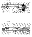
- Fig. 1 is a sectional view showing Embodiment 1 of a metal gasket according to the present invention.
- Fig. 2 is a sectional view showing Embodiment 2 of a metal gasket according to the present invention.
- Fig. 3(a) is a sectional view showing Embodiment 3 of a metal gasket according to the present invention.
- Fig. 3(b) is a sectional view in which a base plate and a sub-plate are fixed by a notch of the sub plate.
- Fig. 4 is a sectional view showing Embodiment 4 of the metal gasket according to the present invention.
- Fig. 5 is a sectional view showing Embodiment 5 of the metal gasket according to the present invention.
- a metal gasket according to the present invention is interposed between a mating surface of an open deck type cylinder block 17, in which a cast type cylinder sleeve 12 (see Fig. 1) or a cylinder liner 11 with a flange 13 (see Fig.
- a cooling water passage 16 is formed endlessly or half-endlessly (which is the state in which the cooling water passage 16 is not formed completely endlessly in the outer periphery of the cylindrical portion 15, but the cylindrical portion 15 and the outer wall 19 are partly connected) in the outer periphery of a cylindrical portion 15 of the cylinder block encircling the cylinder bore 11, and a mating surface of a cylinder head l8.
- the metal gasket shown in Fig. 1 is formed with a base plate 1 formed from a hard stainless steel plate so that the latter can be interposed over both the cylindrical portion 15 of the cylinder block 17 and the outer wall 19 constituting the outside of the cooling water passage 16, and formed with a plurality of cooling water holes 2 leading to the cooling water passage 16.
- a grommet 4 formed, for example, from a soft stainless plate and applied with a molybdenum film 3b to the entire outer surface is provided along the inner periphery of the cylinder bore 11 of the base plate 1.
- the grommet 4 is formed to have an extension piece 5 extending to the vicinity of the inner periphery of the cooling water passage 16 on the side of the cylinder block 17 and to have a turn piece 6 on the side of the cylinder head 18, and the turn piece 6 of the grommet 4 has its outer periphery close to the outside of the cylinder sleeve 12 and a total thickness T1 of the extension piece 5 of the grommet 4 and the base plate 1 put one upon another forms the largest thickness portion 7 thicker than the other parts T2, T3 and T4.
- two difference-in-level beads 9a, 9a are formed in the state in which the base plate 1 and the extension piece 5 of the grommet 4 are in contact with each other from the outside of the turn portion 6 of the grommet 4 to the outer periphery of the cylindrical portion 15 of the cylinder block 17.
- a sub-plate 8 formed, for example, from a soft or hard stainless steel plate or an iron plate is secured to the base plate 1 over the upper surface of the outer wall 19 of the cylinder block 17 by a rivet 10 or the like, a total thickness T3 of the sub-plate 8 and the base plate 1 is smaller to the thickness T1 of the largest thickness portion 7, and difference-in-level beads 9a are formed on both or one of the base plate 1 and the sub-plate 8.
- the difference-in-level beads 9a are formed on both sides parted from the largest thickness portion 7 and the cooling water passage 16 whereby the cooling water flowing through the cooling water passage 16 can be well sealed.
- the largest thickness portion 7 has a load F1 which is far greater than bead loads F2, F3.
- the load F1 of the largest thickness portion 7 forms a primary seal to a clearance between the mating surfaces, and the bead loads F2, F3 form a secondary seal.
- the clearance between the mating surfaces can be double sealed.
- the cylindrical portion 15 of the cylinder block 17 shows its own behavior different from the outer wall 19 of the cylinder block 17 at the time of combustion.
- a molybdenum film 3b excellent in sliding performance is applied to the outside of the grommet 4, even in the state in which the largest thickness portion 7 having the maximum load F1 is held between the cylinder head 18 and the cylindrical portion 15 of the cylinder block 17, it slidably moves with respect to the own behavior of the cylindrical portion 15, whereby no excessive force occurs in the beads or the like, and the beads or the like can be protected satisfactorily.
- the inner peripheral end 4a of the grommet 4 is pressed and collapsed whereby the thickness T4 of the turn piece 6 and the extension piece 5 of the grommet 4 put one upon another is smaller than the largest thickness portion 7.
- a rubber film 3a or a molybdenum film 3b is applied on the side of the cylinder head 18 at the base plate 1.
- the rubber film 3a is applied, there is excellent contact with respect to the surface rough of the cylinder head 18 so that blow-bye of combustion can be well prevented.
- the molybdenum film 3b is applied, it is useful in protection of beads 8 on both sides since the sliding performance is improved.
- the sub-plate 8 to both sides of which the rubber film 3a is applied is secured to the base plate 1 by the rivet 10.
- the rubber film 3a is applied to both sides of the sub-plate 8
- there is provided better contact with respect to the metal surface on the side of the cylinder block 17 at the base plate 1 no exposure to the cooling water passage 16 occurs, and the metal surface on the side of the cylinder block 17 at the base plate 1 does not face to cooling water flowing through the cooling water passage 16 to peel rubber.
- the metal gasket shown in Fig. 2 though construction thereof is substantially similar to Embodiment 1, is interposed between the mating surface of the open deck type cylinder block 17, in which the cylinder liner 14 with a flange 13 is provided on the inner periphery of the cylinder bore 11, and the mating surface of the cylinder head 18.
- the construction of the metal gasket in the figure is formed so that the largest thickness portion 7 is positioned in the flange 13 of the cylinder liner 14.
- the maximum load of the largest thickness portion 7 presses the flange 13 of the cylinder liner 14 so as to act on the difference-in-level of the cylinder block 17 supporting the flange 13 to prevent depression and deformation of the cylinder liner 14.
- the molybdenum film 3b having a good sliding performance is applied to the outside of the grommet 4, the largest thickness portion 7 slidably moves with respect to the behavior of the cylindrical portion 15 of the cylinder block 17 whereby no forcible force applies to the beads or the like, and the beads or the like can be protected satisfactorily.
- both are engaged in difference-in-level shape to improve the adhesive property, and the beads can be formed simultaneously on the sub-plate 8 and the base plate 1 thus matched.
- the extension piece 5 of the grommet 4 and the base plate 1 form the different-in-level beads 9a with a clearance 20 above the cylindrical portion 15 of the cylinder block 17. While the beads of the base plate 1 and the beads of the extension piece 5 of the grommet 4 come closely in contact with one another have a spring force totaling the bead loads of both beads, as in Embodiment 1, both beads according to Embodiment 2 are separated, whereby the loads of both separated beads are distributed, so that both separated beads can exhibit bead loads smaller than the bead loads of the beads closely in contact.
- the metal gasket shown in Fig. 3(b) is, though construction thereof is substantially similar to Embodiment 1, different from Embodiment 1 in a difference-in-level beads 9a formed at the extension piece 5 of the grommet 4 and the method of securing a sub-plate 8 on the base plate 1.
- the base plate 1 is formed with two-stage difference-in-level beads 9a.
- the extension piece 5 of the grommet 4 is formed into a convex difference-in-level to meet the difference-in-level beads 9a on the lower stage side of the base plate 1 and to reversibly part from the difference-in-level beads 9a on the upper stage side of the base plate 1.
- the method of securing the sub-plate 8 to the base plate 1 comprises a securing means comprising: applying rubber films 3a to both surfaces of the sub-plate 8, and inserting into a through-bole 10b provided in the base plate 4 with a notch lOa of the sub-plate 8 stood upright and turning it, as shown in Fig. 3(b).
- the metal gasket shown in Fig. 4 is, though construction thereof is substantially similar to Embodiment I, different from Embodiment 1 in the beads formed above the cylindrical portion 15 of the cylinder block 17, in the beads of the grommet 4, and in the difference-in-level beads 9a of the base plate 1 and the sub-plate 8 formed above the outer wall 19 of the cylinder block 17.
- the beads of the base plate 1 formed above the cylindrical portion 15 of the cylinder block 17 are formed into the difference-in-level beads 9a in the vicinity of the turn piece 6 of the grommet 4, the beads 9b circular in section are formed externally thereof, the difference-in-level beads 9a formed on the extension piece 5 of the grommet 4 are placed upon the difference-in-level beads 9a of the base plate 1, and the similar beads 9b circular in section are formed on the side opposite to the beads 9b circular in section of the base plate 1.
- difference-in-level beads 9a, 9a of the base plate 1 and the sub-plate 8 formed above the outer wall 19 of the cylinder block 17 are formed into the difference-in-level beads 9a in the direction opposed to each other, which beads 9a are substantially registered in bead height with the beads 9b circular in section on the side of the cylindrical portion 15 of the cylinder block 17 so as to provide a balance in the bead height therebetween.
- the metal gasket of Fig. 5 is interposed between the mating surface of the open deck type cylinder block 17, in which the cylinder liner 14 with a flange 13 is provided in the inner periphery of the cylinder bore 11, and the mating surface of the cylinder head 18.
- the present metal gasket also is, though construction thereof is substantially similar to Embodiment 1, different from Embodiment 1 in the bead construction formed above the cylindrical portion 15 of the cylinder block 17, in the bead construction of the base plate 1 formed above the cuter wall 19 of the cylinder block 1, and in the sub-plate 8.
- the difference-in-level beads 9a are formed on the intermediate plate 21, materials of the intermediate plate 21 are selected to adjust the hardness of materials, and the clearance 20 is varied whereby the bead load in the secondary seal can be increased and adjusted.
- the difference-in-level beads 9a are formed in the vicinity of the cooling water passage 16 of the base plate 1 and in a state of close contact with the flat sub-plate 8 applied with the rubber films 3a to both surfaces, the beads 9b circular in section are formed externally thereof via the fastening portion of a bolt 23 inserted into the bolt hole 22, and both the sub-plate 8 and the base plate 1 are fixed by the rivet 10.
- the load of the entire metal gasket is that the turn piece of the grommet has its outer periphery close to the outside of the cylinder sleeve or on the upper surface of the flange of the cylinder liner and there provides the greatest load in the largest thickness portion of the extension piece of the grommet and the base plate placed upon one another to provide a primary seal with respect to the clearance between the mating surfaces of the cylinder head and the cylinder block, and the beads formed on the base plate and the extension piece of the grommet from the outside of the turn piece of the grommet to the outer periphery of the cylindrical portion of the cylinder block, and the beads formed on both or one of the sub-plate over the upper surface of the outer wall of the cylinder block and the base plate secured to thereto provide a secondary seal, and the clearance of the mating surface can be double sealed.
- the largest thickness portion applied with the molybdenum film excellent in sliding performance externally of the grommet is in the state sandwiched between the cylinder head and the cylindrical portion of the cylinder block.
- the metal gasket is inserted between the mating surface of the open deck type cylinder block, in which the cooling water passage is formed endlessly or half-endlessly in the outer periphery of the cylindrical portion encircling the cylinder bore, and the mating surface of the cylinder head and bolted at the outer wall, in which case it slidably moves with respect to the cylindrical portion indicative of its own behavior different from the outer wall of the cylinder block at the time of combustion explosion, whereby no forcible force occurs in beads or the like, and these can be protected satisfactorily.
- the inner peripheral end of the grommet is not in contact with the upper surface of the cylinder sleeve, and no depression or deformation occurs in the cylinder sleeve.
Abstract
Description
- The present invention relates to a metal gasket interposed between a mating surface of an open deck type cylinder block, in which a cast type cylinder sleeve or a cylinder liner with a flange is provided in the inner periphery of a cylinder bore and a cooling water passage is formed endlessly or half-endlessly in the outer periphery of a cylindrical portion encircling the cylinder bore, and a mating surface of a cylinder head.
- In recent gasoline engines or diesel engines, it has been generalized, in order to reduce the weight and to speed up the production, the cylinder heads and the cylinder blocks have been formed of aluminum.
- Among them, the cylinder block is produced using the diecast method as the procedure for enhancing productivity. Unlike the low pressure casting method, diecast casting is the procedure, which requires no "core", and in which casting, cooling and removal of products are carried out by metallic molds with a draft, thereby realizing short tact periods.
- In the cylinder block formed by the diecasting as described above, the open deck type is employed in which a cooling water passage is formed endlessly in the outer periphery of the cylindrical portion encircling the cylinder bore.
- In the case where the metal gasket is interposed between the mating surfaces of the cylinder head and the cylinder block, bolting is made in the state in which the metal gasket is sandwiched between the outer wall of the cylinder block and the cylinder head, and therefore when the engine is operated under load, the cylindrical portion of the cylinder block shows independent behavior different from the outer wall of the cylinder block having a bolted portion. Because of this, the metal gasket comes in contact with the upper surface of the cylindrical portion of the cylinder block and vibrates, thus posing a problem in that roughness occurs on the surface of the metal gasket, cracks occur in beads formed on the metal gasket, and blow-by of combustion gas from the cylinder bore tends to occur.
- On the other hand, in the case where the inner periphery of the cylinder bore has a cast type cylinder sleeve or a cylinder liner with a flange, there occurs the problem in that due to the bolting force or the pressing force of the metal gasket at the time of combustion, a depression occurs in the cylinder sleeve or the cylinder liner, resulting in deformation.
- The present invention is achieved in order to overcome these problems as noted above. An object of the present
invention is to provide a metal gasket interposed between a mating surface of an open deck type cylinder block, in which a cast type cylinder sleeve or a cylinder liner with a flange is provided in the inner periphery of a cylinder bore and a cooling water passage is formed endlessly or half-endlessly in the outer periphery of a cylindrical portion encircling the cylinder bore, and a mating surface of a cylinder head, whereby a depression or deformation of the cylinder sleeve or the cylinder liner is prevented, and a sealing performance of high durability is secured. - For achieving the aforesaid object, according to the present invention, there is provided a metal gasket interposed between a mating surface of an open deck type cylinder block, in which a cast type cylinder sleeve or a cylinder liner with a flange is provided in the inner periphery of cylinder bore and a cooling water passage is formed endlessly or half-endlessly in the outer periphery of a cylindrical portion encircling the cylinder bore, and a mating surface of a cylinder bead, characterized in that a grommet applied with a molybdenum film on the outer surface thereof is provided, along the inner periphery of the cylinder bore, at a base plate interposed over both the cylindrical portion of said cylinder block and an outer wall forming the outside of said cooling water passage, said grommet having an extension piece extending to the vicinity of the inner periphery of said cooling water passage on the cylinder block side and having a turn piece on the cylinder head side, said turn piece having its outer periphery close to the outside of said cylinder sleeve or on the upper surface of the flange of said cylinder liner, the total thickness of the extension piece of said grommet and said base plate put one upon another is larger in thickness and thicker than the other parts, beads are formed on said base plate and the extension piece of said grommet from the outside of the turn piece of said grommet to the outer periphery of the cylindrical portion of said cylinder block, whereas the total thickness of a sub-plate over the upper surface of the outer wall of said cylinder block secured to said base plate is smaller than said largest thickness portion, and both of or one of said base plate and said sub-plate (are) is formed with beads.
- Preferably, the inner peripheral end of said grommet, in the inner peripheral side of the cylinder bore, at said base plate is pressed whereby the thickness of the turn piece and the extension piece put of said grommet upon another is smaller than said largest thickness portion.
- Preferably, a molybdenum film is applied to the outer surface of the grommet.
- Preferably, rubber film or molybdenum is applied to the other portions than said grommet.
- Alternatively, the rubber film is applied to a contact surface on the base plate side of said sub-plate to secure said sub-plate to said base plate by securing means such as a rivet or the like.
- Alternatively, the contact surface on the base plate side of said sub-plate is not provided with a film, and beads are formed in the state in which said sub-plate is secured to said base plate by an adhesive.
- The embodiments of the present invention will be described hereinafter with reference to the drawings.
- Fig. 1 is a sectional
view showing Embodiment 1 of a metal gasket according to the present invention. Fig. 2 is a sectionalview showing Embodiment 2 of a metal gasket according to the present invention. Fig. 3(a) is a sectional view showing Embodiment 3 of a metal gasket according to the present invention. Fig. 3(b) is a sectional view in which a base plate and a sub-plate are fixed by a notch of the sub plate. Fig. 4 is a sectionalview showing Embodiment 4 of the metal gasket according to the present invention. Fig. 5 is a sectionalview showing Embodiment 5 of the metal gasket according to the present invention. - As shown in Figs. 1 and 2, a metal gasket according to the present invention is interposed between a mating surface of an open deck
type cylinder block 17, in which a cast type cylinder sleeve 12 (see Fig. 1) or acylinder liner 11 with a flange 13 (see Fig. 2 or 5) is provided in the inner periphery of acylinder bore 11 and acooling water passage 16 is formed endlessly or half-endlessly (which is the state in which thecooling water passage 16 is not formed completely endlessly in the outer periphery of thecylindrical portion 15, but thecylindrical portion 15 and theouter wall 19 are partly connected) in the outer periphery of acylindrical portion 15 of the cylinder block encircling thecylinder bore 11, and a mating surface of a cylinder head l8. - The metal gasket shown in Fig. 1 is formed with a
base plate 1 formed from a hard stainless steel plate so that the latter can be interposed over both thecylindrical portion 15 of thecylinder block 17 and theouter wall 19 constituting the outside of thecooling water passage 16, and formed with a plurality ofcooling water holes 2 leading to thecooling water passage 16. - A
grommet 4 formed, for example, from a soft stainless plate and applied with amolybdenum film 3b to the entire outer surface is provided along the inner periphery of the cylinder bore 11 of thebase plate 1. Thegrommet 4 is formed to have anextension piece 5 extending to the vicinity of the inner periphery of thecooling water passage 16 on the side of thecylinder block 17 and to have aturn piece 6 on the side of thecylinder head 18, and theturn piece 6 of thegrommet 4 has its outer periphery close to the outside of thecylinder sleeve 12 and a total thickness T1 of theextension piece 5 of thegrommet 4 and thebase plate 1 put one upon another forms thelargest thickness portion 7 thicker than the other parts T2, T3 and T4. - Further, two difference-in-
level beads base plate 1 and theextension piece 5 of thegrommet 4 are in contact with each other from the outside of theturn portion 6 of thegrommet 4 to the outer periphery of thecylindrical portion 15 of thecylinder block 17. - On the other hand, a
sub-plate 8 formed, for example, from a soft or hard stainless steel plate or an iron plate is secured to thebase plate 1 over the upper surface of theouter wall 19 of thecylinder block 17 by arivet 10 or the like, a total thickness T3 of thesub-plate 8 and thebase plate 1 is smaller to the thickness T1 of thelargest thickness portion 7, and difference-in-level beads 9a are formed on both or one of thebase plate 1 and thesub-plate 8. - As described above, the difference-in-
level beads 9a are formed on both sides parted from thelargest thickness portion 7 and thecooling water passage 16 whereby the cooling water flowing through thecooling water passage 16 can be well sealed. - In the case where the metal gasket of Fig. 1 is interposed between the mating surface of the
cylinder head 18 and the mating surface of thecylinder block 17 and bolted at the position of theouter wall 19 of thecylinder block 17, as shown in Fig. 5, thelargest thickness portion 7 has a load F1 which is far greater than bead loads F2, F3. The load F1 of thelargest thickness portion 7 forms a primary seal to a clearance between the mating surfaces, and the bead loads F2, F3 form a secondary seal. The clearance between the mating surfaces can be double sealed. - Further, the
cylindrical portion 15 of thecylinder block 17 shows its own behavior different from theouter wall 19 of thecylinder block 17 at the time of combustion. However, since amolybdenum film 3b excellent in sliding performance is applied to the outside of thegrommet 4, even in the state in which thelargest thickness portion 7 having the maximum load F1 is held between thecylinder head 18 and thecylindrical portion 15 of thecylinder block 17, it slidably moves with respect to the own behavior of thecylindrical portion 15, whereby no excessive force occurs in the beads or the like, and the beads or the like can be protected satisfactorily. - Further, the inner
peripheral end 4a of thegrommet 4 is pressed and collapsed whereby the thickness T4 of theturn piece 6 and theextension piece 5 of thegrommet 4 put one upon another is smaller than thelargest thickness portion 7. - While the inner
peripheral end 4a of thegrommet 4 in Fig. 1 is in the state in which theturn piece 6 and theextension piece 5 are pressed, it is noted that both need not always be in contact with each other, but a clearance (Fig. 5) may be formed between theturn piece 6 and theextension piece 5. The innerperipheral end 4a of thegrommet 4 does not come in contact with the upper surface of thecylinder sleeve 12, and depression or deformation of thecylinder sleeve 12 does not occur. - Further, in the metal gasket in Fig. 1, a
rubber film 3a or amolybdenum film 3b is applied on the side of thecylinder head 18 at thebase plate 1. In the case where therubber film 3a is applied, there is excellent contact with respect to the surface rough of thecylinder head 18 so that blow-bye of combustion can be well prevented. In the case where themolybdenum film 3b is applied, it is useful in protection ofbeads 8 on both sides since the sliding performance is improved. - Further, the
sub-plate 8 to both sides of which therubber film 3a is applied is secured to thebase plate 1 by therivet 10. In case where therubber film 3a is applied to both sides of thesub-plate 8, there is provided better contact with respect to the metal surface on the side of thecylinder block 17 at thebase plate 1, no exposure to thecooling water passage 16 occurs, and the metal surface on the side of thecylinder block 17 at thebase plate 1 does not face to cooling water flowing through thecooling water passage 16 to peel rubber. - The metal gasket shown in Fig. 2, though construction thereof is substantially similar to
Embodiment 1, is interposed between the mating surface of the open decktype cylinder block 17, in which thecylinder liner 14 with aflange 13 is provided on the inner periphery of thecylinder bore 11, and the mating surface of thecylinder head 18. - The construction of the metal gasket in the figure is formed so that the
largest thickness portion 7 is positioned in theflange 13 of thecylinder liner 14. The maximum load of thelargest thickness portion 7 presses theflange 13 of thecylinder liner 14 so as to act on the difference-in-level of thecylinder block 17 supporting theflange 13 to prevent depression and deformation of thecylinder liner 14. - Further, since the
molybdenum film 3b having a good sliding performance is applied to the outside of thegrommet 4, thelargest thickness portion 7 slidably moves with respect to the behavior of thecylindrical portion 15 of thecylinder block 17 whereby no forcible force applies to the beads or the like, and the beads or the like can be protected satisfactorily. - Other points which distinguish the present metal gasket as different from that
Embodiment 1 are as follows: Therubber film 3a is applied only on the side of thecylinder block 17 at thesub-plate 8, the contact surface on the side of thebase plate 1 at thesub-plate 8 has no film, and the beads are formed in the state in which thesub-late 8 is secured to thebase plate 1 by the adhesive. - By doing so, both are engaged in difference-in-level shape to improve the adhesive property, and the beads can be formed simultaneously on the
sub-plate 8 and thebase plate 1 thus matched. - The
extension piece 5 of thegrommet 4 and thebase plate 1 form the different-in-level beads 9a with aclearance 20 above thecylindrical portion 15 of thecylinder block 17. While the beads of thebase plate 1 and the beads of theextension piece 5 of thegrommet 4 come closely in contact with one another have a spring force totaling the bead loads of both beads, as inEmbodiment 1, both beads according toEmbodiment 2 are separated, whereby the loads of both separated beads are distributed, so that both separated beads can exhibit bead loads smaller than the bead loads of the beads closely in contact. - The metal gasket shown in Fig. 3(b) is, though construction thereof is substantially similar to
Embodiment 1, different fromEmbodiment 1 in a difference-in-level beads 9a formed at theextension piece 5 of thegrommet 4 and the method of securing asub-plate 8 on thebase plate 1. - That is, above the
cylindrical portion 15 of thecylinder block 17, thebase plate 1 is formed with two-stage difference-in-level beads 9a. However, theextension piece 5 of thegrommet 4 is formed into a convex difference-in-level to meet the difference-in-level beads 9a on the lower stage side of thebase plate 1 and to reversibly part from the difference-in-level beads 9a on the upper stage side of thebase plate 1. By the bead shape of theextension piece 5 of thegrommet 4 as described above, the bead load totaled to the beads of thebase plate 1 can be made higher than the beads closely in contact, enabling the enhancement of the secondary sealing performance provided by these beads. - The method of securing the
sub-plate 8 to thebase plate 1 comprises a securing means comprising: applyingrubber films 3a to both surfaces of thesub-plate 8, and inserting into a through-bole 10b provided in thebase plate 4 with a notch lOa of thesub-plate 8 stood upright and turning it, as shown in Fig. 3(b). - The metal gasket shown in Fig. 4 is, though construction thereof is substantially similar to Embodiment I, different from
Embodiment 1 in the beads formed above thecylindrical portion 15 of thecylinder block 17, in the beads of thegrommet 4, and in the difference-in-level beads 9a of thebase plate 1 and the sub-plate 8 formed above theouter wall 19 of thecylinder block 17. - That is, the beads of the
base plate 1 formed above thecylindrical portion 15 of thecylinder block 17 are formed into the difference-in-level beads 9a in the vicinity of theturn piece 6 of thegrommet 4, thebeads 9b circular in section are formed externally thereof, the difference-in-level beads 9a formed on theextension piece 5 of thegrommet 4 are placed upon the difference-in-level beads 9a of thebase plate 1, and thesimilar beads 9b circular in section are formed on the side opposite to thebeads 9b circular in section of thebase plate 1. By doing so, it is possible to form thebeads 9b circular in section, contributing to the enhancement of the secondary sealing property due to the bead shape circular in section. - Further, the difference-in-
level beads base plate 1 and the sub-plate 8 formed above theouter wall 19 of thecylinder block 17 are formed into the difference-in-level beads 9a in the direction opposed to each other, whichbeads 9a are substantially registered in bead height with thebeads 9b circular in section on the side of thecylindrical portion 15 of thecylinder block 17 so as to provide a balance in the bead height therebetween. - The metal gasket of Fig. 5 is interposed between the mating surface of the open deck
type cylinder block 17, in which thecylinder liner 14 with aflange 13 is provided in the inner periphery of the cylinder bore 11, and the mating surface of thecylinder head 18. - The present metal gasket also is, though construction thereof is substantially similar to
Embodiment 1, different fromEmbodiment 1 in the bead construction formed above thecylindrical portion 15 of thecylinder block 17, in the bead construction of thebase plate 1 formed above thecuter wall 19 of thecylinder block 1, and in thesub-plate 8. - That is, in the state in which above the
cylindrical portion 15 of thecylinder block 17, anintermediate plate 21 is inserted between thebase plate 1 and theextension piece 5 of thegrommet 4, two-stage difference-in-level beads 9a are formed on thebase plate 1 and theextension piece 5 of thegrommet 4, and aclearance 20 is formed between thebeads - As described above, the difference-in-
level beads 9a are formed on theintermediate plate 21, materials of theintermediate plate 21 are selected to adjust the hardness of materials, and theclearance 20 is varied whereby the bead load in the secondary seal can be increased and adjusted. - Also, above the
outer wall 19 of thecylinder block 17, the difference-in-level beads 9a are formed in the vicinity of the coolingwater passage 16 of thebase plate 1 and in a state of close contact with theflat sub-plate 8 applied with therubber films 3a to both surfaces, thebeads 9b circular in section are formed externally thereof via the fastening portion of abolt 23 inserted into thebolt hole 22, and both thesub-plate 8 and thebase plate 1 are fixed by therivet 10. - As described above, according to the metal gasket of the present invention, the load of the entire metal gasket is that the turn piece of the grommet has its outer periphery close to the outside of the cylinder sleeve or on the upper surface of the flange of the cylinder liner and there provides the greatest load in the largest thickness portion of the extension piece of the grommet and the base plate placed upon one another to provide a primary seal with respect to the clearance between the mating surfaces of the cylinder head and the cylinder block, and the beads formed on the base plate and the extension piece of the grommet from the outside of the turn piece of the grommet to the outer periphery of the cylindrical portion of the cylinder block, and the beads formed on both or one of the sub-plate over the upper surface of the outer wall of the cylinder block and the base plate secured to thereto provide a secondary seal, and the clearance of the mating surface can be double sealed.
- Further, in the metal gasket according to the present invention, the largest thickness portion applied with the molybdenum film excellent in sliding performance externally of the grommet is in the state sandwiched between the cylinder head and the cylindrical portion of the cylinder block. The metal gasket is inserted between the mating surface of the open deck type cylinder block, in which the cooling water passage is formed endlessly or half-endlessly in the outer periphery of the cylindrical portion encircling the cylinder bore, and the mating surface of the cylinder head and bolted at the outer wall, in which case it slidably moves with respect to the cylindrical portion indicative of its own behavior different from the outer wall of the cylinder block at the time of combustion explosion, whereby no forcible force occurs in beads or the like, and these can be protected satisfactorily.
- Further, since the largest thickness portion exhibits the maximum load of the metal gasket close to the outside of the cylinder sleeve or on the upper surface of the flange of the cylinder liner, the inner peripheral end of the grommet is not in contact with the upper surface of the cylinder sleeve, and no depression or deformation occurs in the cylinder sleeve.
-
- Fig. I
- is a sectional
view showing Embodiment 1 of a metal gasket according to the present invention. - Fig. 2
- is a sectional
view showing Embodiment 2 of a metal gasket according to the present invention. - Fig. 3(a)
- is a sectional view showing Embodiment 3 of the present invention, and
- Fig. 3(b)
- is a sectional view in which a base plate and a sub-plate are secured by a notch of the sub-plate.
- Fig. 4
- is a sectional
view showing Embodiment 4 of a metal gasket according to the present invention. - Fig. 5
- is a sectional
view showing Embodiment 5 of a metal gasket according to the present invention.
Claims (5)
- A metal gasket interposed between a mating surface of an open deck type cylinder block (17), in which a cast type cylinder sleeve or a cylinder liner (12) with a flange (13) is provided in the inner periphery of a cylinder bore (11) and a cool water passage (16) is formed endlessly or half-endlessly in the outer periphery of a cylindrical portion encircling the cylinder bore (11), and a mating surface of a cylinder head (10), characterized in that a grommet (4) applied with a molybdenum film on the outer surface thereof is provided, along the inner periphery of the cylinder bore (11), at a base plate (1) interposed over both the cylindrical portion of said cylinder block (17) and an outer wall (19) forming the outside of said cooling water passage (16), said grommet (4) having an extension piece (5) extending to the vicinity of the inner periphery of said cooling water passage (16) on the cylinder block (17) side and having a turn piece (6) on the cylinder head (18) side, said turn piece (6) having its outer periphery close to the outside of said cylinder sleeve (12) or on the upper surface of the flange (13) of said cylinder liner (14), the total thickness of the extension piece of said grommet (4) and said base plate (1) put one upon another is the largest thickness thicker than other parts, beads are formed on said base plate (1) and the extension piece (5) of said grommet (4) from the outside of the turn portion (6) of said grommet (4) to the outer periphery of the cylindrical portion (15) of said cylinder block (17), whereas the total thickness of a sub-plate (8) over the upper surface of the outer wall (19) of said cylinder block (17) secured to said base plate (1) is smaller than said largest thickness portion (7), and both of or one of said base plate (1) and said sub-plate (8) are, (is) formed with beads.
- The metal gasket of claim 1, wherein the inner peripheral end of said grommet (4), in the inner peripheral side of the cylinder bore (11), at said base plate (1) is pressed whereby the thickness of the turn portion (6) and the extension piece of said grommet (4) put upon another is smaller than said largest thickness portion (7).
- The metal gasket of claim 1, wherein a rubber film (3a) or a molybdenum film (3b) is applied to portions other than said grommet (4).
- The metal gasket of claim 1, wherein the rubber film (3a) is applied to a contact surface on the base plate side of said sub-plate (8) to secure said sub-plate (8) to said base plate (1) by securing means such as a rivet (10) or the like.
- The metal gasket of claim 1, wherein the contact surface on the base plate side of said sub-plate (8) is not provided with a film (3), and beads are formed in a state in which said sub-plate (8) is secured to said base plate (1) by an adhesive.
Priority Applications (2)
| Application Number | Priority Date | Filing Date | Title |
|---|---|---|---|
| EP19980106866 EP0950807B1 (en) | 1998-04-16 | 1998-04-16 | Metal gasket |
| DE1998606120 DE69806120T2 (en) | 1998-04-16 | 1998-04-16 | Metallic flat gasket |
Applications Claiming Priority (1)
| Application Number | Priority Date | Filing Date | Title |
|---|---|---|---|
| EP19980106866 EP0950807B1 (en) | 1998-04-16 | 1998-04-16 | Metal gasket |
Publications (2)
| Publication Number | Publication Date |
|---|---|
| EP0950807A1 true EP0950807A1 (en) | 1999-10-20 |
| EP0950807B1 EP0950807B1 (en) | 2002-06-19 |
Family
ID=8231766
Family Applications (1)
| Application Number | Title | Priority Date | Filing Date |
|---|---|---|---|
| EP19980106866 Expired - Lifetime EP0950807B1 (en) | 1998-04-16 | 1998-04-16 | Metal gasket |
Country Status (2)
| Country | Link |
|---|---|
| EP (1) | EP0950807B1 (en) |
| DE (1) | DE69806120T2 (en) |
Cited By (4)
| Publication number | Priority date | Publication date | Assignee | Title |
|---|---|---|---|---|
| DE10123487B4 (en) * | 2001-05-15 | 2005-04-07 | Elringklinger Ag | Cylinder head gasket for engines with cylinder liners |
| WO2008009318A1 (en) * | 2006-07-15 | 2008-01-24 | Elringklinger Ag | Flat seal |
| WO2016114323A1 (en) * | 2015-01-14 | 2016-07-21 | Nok株式会社 | Gasket |
| CN111465787A (en) * | 2017-12-11 | 2020-07-28 | K&K株式会社 | Sealing gasket |
Families Citing this family (2)
| Publication number | Priority date | Publication date | Assignee | Title |
|---|---|---|---|---|
| DE102009008791A1 (en) * | 2009-02-13 | 2010-09-16 | Federal-Mogul Sealing Systems Gmbh | Flat seals with additional sealing element |
| DE102012219808A1 (en) * | 2012-10-30 | 2014-04-30 | Federal-Mogul Sealing Systems Gmbh | Metal elastomer seal with integrated dirt and media seal |
Citations (3)
| Publication number | Priority date | Publication date | Assignee | Title |
|---|---|---|---|---|
| JPH07119837A (en) * | 1993-10-22 | 1995-05-12 | Ket & Ket:Kk | Metallic gasket |
| JPH09152036A (en) * | 1995-12-04 | 1997-06-10 | Ket & Ket:Kk | Metal gasket |
| JPH102421A (en) * | 1996-06-13 | 1998-01-06 | Ket & Ket:Kk | Metallic gasket |
-
1998
- 1998-04-16 EP EP19980106866 patent/EP0950807B1/en not_active Expired - Lifetime
- 1998-04-16 DE DE1998606120 patent/DE69806120T2/en not_active Expired - Fee Related
Patent Citations (3)
| Publication number | Priority date | Publication date | Assignee | Title |
|---|---|---|---|---|
| JPH07119837A (en) * | 1993-10-22 | 1995-05-12 | Ket & Ket:Kk | Metallic gasket |
| JPH09152036A (en) * | 1995-12-04 | 1997-06-10 | Ket & Ket:Kk | Metal gasket |
| JPH102421A (en) * | 1996-06-13 | 1998-01-06 | Ket & Ket:Kk | Metallic gasket |
Non-Patent Citations (3)
| Title |
|---|
| PATENT ABSTRACTS OF JAPAN vol. 95, no. 8 29 September 1995 (1995-09-29) * |
| PATENT ABSTRACTS OF JAPAN vol. 97, no. 10 30 October 1997 (1997-10-30) * |
| PATENT ABSTRACTS OF JAPAN vol. 98, no. 5 30 April 1998 (1998-04-30) * |
Cited By (8)
| Publication number | Priority date | Publication date | Assignee | Title |
|---|---|---|---|---|
| DE10123487B4 (en) * | 2001-05-15 | 2005-04-07 | Elringklinger Ag | Cylinder head gasket for engines with cylinder liners |
| WO2008009318A1 (en) * | 2006-07-15 | 2008-01-24 | Elringklinger Ag | Flat seal |
| US8646783B2 (en) | 2006-07-15 | 2014-02-11 | Elringklinger Ag | Flat gasket |
| EP3115656A1 (en) * | 2006-07-15 | 2017-01-11 | ElringKlinger AG | Flat gasket |
| WO2016114323A1 (en) * | 2015-01-14 | 2016-07-21 | Nok株式会社 | Gasket |
| CN107110359A (en) * | 2015-01-14 | 2017-08-29 | Nok株式会社 | Pad |
| CN111465787A (en) * | 2017-12-11 | 2020-07-28 | K&K株式会社 | Sealing gasket |
| CN111465787B (en) * | 2017-12-11 | 2023-10-24 | K&K株式会社 | Sealing gasket |
Also Published As
| Publication number | Publication date |
|---|---|
| DE69806120D1 (en) | 2002-07-25 |
| EP0950807B1 (en) | 2002-06-19 |
| DE69806120T2 (en) | 2005-02-17 |
Similar Documents
| Publication | Publication Date | Title |
|---|---|---|
| US6827352B2 (en) | Metal gasket | |
| US6283480B1 (en) | Metal gasket | |
| US6076833A (en) | Metal gasket | |
| EP0459060B1 (en) | Metallic gasket | |
| JPH086805B2 (en) | Metal gasket | |
| EP0866245A3 (en) | Metal gasket | |
| EP1564453A1 (en) | Cylinder head gasket | |
| US20060017232A1 (en) | Metal gasket | |
| KR100950000B1 (en) | Cylinder head gasket | |
| EP0833087A1 (en) | Metal gasket with bead and thermal sprayed layer thereof | |
| US7311309B2 (en) | Cylinder head gasket | |
| EP1094258B1 (en) | Metal gasket assembly for cylinder head | |
| EP0950807A1 (en) | Metal gasket | |
| JP2753779B2 (en) | Molding method of metal gasket and stopper | |
| JP2005180596A (en) | Metal laminate type gasket | |
| US7108268B2 (en) | Metal laminate gasket | |
| JP2932375B2 (en) | Metal gasket | |
| JP2003322256A (en) | Metal gasket | |
| JP2002005292A (en) | Metal gasket | |
| JPH08114266A (en) | Metal gasket | |
| JPH09303560A (en) | Metallic gasket | |
| EP1180621A3 (en) | Cylinder head gasket with partial resin layer | |
| KR200297475Y1 (en) | Metal gasket with multi stopper structure | |
| JPH0488265A (en) | Metal gasket | |
| JP2002349345A (en) | Combining sealing method and multicylindered engine |
Legal Events
| Date | Code | Title | Description |
|---|---|---|---|
| PUAI | Public reference made under article 153(3) epc to a published international application that has entered the european phase |
Free format text: ORIGINAL CODE: 0009012 |
|
| 17P | Request for examination filed |
Effective date: 19981016 |
|
| AK | Designated contracting states |
Kind code of ref document: A1 Designated state(s): AT BE CH CY DE DK ES FI FR GB GR IE IT LI LU MC NL PT SE Kind code of ref document: A1 Designated state(s): DE FR GB IT SE |
|
| AX | Request for extension of the european patent |
Free format text: AL;LT;LV;MK;RO;SI |
|
| AKX | Designation fees paid |
Free format text: DE FR GB IT SE |
|
| 17Q | First examination report despatched |
Effective date: 20000711 |
|
| GRAG | Despatch of communication of intention to grant |
Free format text: ORIGINAL CODE: EPIDOS AGRA |
|
| GRAG | Despatch of communication of intention to grant |
Free format text: ORIGINAL CODE: EPIDOS AGRA |
|
| GRAH | Despatch of communication of intention to grant a patent |
Free format text: ORIGINAL CODE: EPIDOS IGRA |
|
| RAP1 | Party data changed (applicant data changed or rights of an application transferred) |
Owner name: CARL FREUDENBERG KG |
|
| GRAH | Despatch of communication of intention to grant a patent |
Free format text: ORIGINAL CODE: EPIDOS IGRA |
|
| GRAA | (expected) grant |
Free format text: ORIGINAL CODE: 0009210 |
|
| AK | Designated contracting states |
Kind code of ref document: B1 Designated state(s): DE FR GB IT SE |
|
| REG | Reference to a national code |
Ref country code: GB Ref legal event code: FG4D |
|
| REF | Corresponds to: |
Ref document number: 69806120 Country of ref document: DE Date of ref document: 20020725 |
|
| ET | Fr: translation filed | ||
| PLBE | No opposition filed within time limit |
Free format text: ORIGINAL CODE: 0009261 |
|
| STAA | Information on the status of an ep patent application or granted ep patent |
Free format text: STATUS: NO OPPOSITION FILED WITHIN TIME LIMIT |
|
| 26N | No opposition filed |
Effective date: 20030320 |
|
| PGFP | Annual fee paid to national office [announced via postgrant information from national office to epo] |
Ref country code: DE Payment date: 20060316 Year of fee payment: 9 |
|
| PGFP | Annual fee paid to national office [announced via postgrant information from national office to epo] |
Ref country code: FR Payment date: 20060418 Year of fee payment: 9 Ref country code: SE Payment date: 20060418 Year of fee payment: 9 |
|
| PGFP | Annual fee paid to national office [announced via postgrant information from national office to epo] |
Ref country code: IT Payment date: 20060430 Year of fee payment: 9 |
|
| GBPC | Gb: european patent ceased through non-payment of renewal fee |
Effective date: 20070416 |
|
| PG25 | Lapsed in a contracting state [announced via postgrant information from national office to epo] |
Ref country code: DE Free format text: LAPSE BECAUSE OF NON-PAYMENT OF DUE FEES Effective date: 20071101 |
|
| PG25 | Lapsed in a contracting state [announced via postgrant information from national office to epo] |
Ref country code: GB Free format text: LAPSE BECAUSE OF NON-PAYMENT OF DUE FEES Effective date: 20070416 |
|
| PG25 | Lapsed in a contracting state [announced via postgrant information from national office to epo] |
Ref country code: SE Free format text: LAPSE BECAUSE OF NON-PAYMENT OF DUE FEES Effective date: 20070417 |
|
| PG25 | Lapsed in a contracting state [announced via postgrant information from national office to epo] |
Ref country code: FR Free format text: LAPSE BECAUSE OF NON-PAYMENT OF DUE FEES Effective date: 20070430 |
|
| PGFP | Annual fee paid to national office [announced via postgrant information from national office to epo] |
Ref country code: GB Payment date: 20060322 Year of fee payment: 9 |
|
| PG25 | Lapsed in a contracting state [announced via postgrant information from national office to epo] |
Ref country code: IT Free format text: LAPSE BECAUSE OF NON-PAYMENT OF DUE FEES Effective date: 20070416 |