EP0950199B1 - Apparatus for sensing vehicles - Google Patents
Apparatus for sensing vehicles Download PDFInfo
- Publication number
- EP0950199B1 EP0950199B1 EP97918693A EP97918693A EP0950199B1 EP 0950199 B1 EP0950199 B1 EP 0950199B1 EP 97918693 A EP97918693 A EP 97918693A EP 97918693 A EP97918693 A EP 97918693A EP 0950199 B1 EP0950199 B1 EP 0950199B1
- Authority
- EP
- European Patent Office
- Prior art keywords
- support section
- sections
- conduit
- support
- probe
- Prior art date
- Legal status (The legal status is an assumption and is not a legal conclusion. Google has not performed a legal analysis and makes no representation as to the accuracy of the status listed.)
- Expired - Lifetime
Links
Images



Classifications
-
- G—PHYSICS
- G08—SIGNALLING
- G08G—TRAFFIC CONTROL SYSTEMS
- G08G1/00—Traffic control systems for road vehicles
- G08G1/01—Detecting movement of traffic to be counted or controlled
- G08G1/042—Detecting movement of traffic to be counted or controlled using inductive or magnetic detectors
-
- G—PHYSICS
- G01—MEASURING; TESTING
- G01V—GEOPHYSICS; GRAVITATIONAL MEASUREMENTS; DETECTING MASSES OR OBJECTS; TAGS
- G01V3/00—Electric or magnetic prospecting or detecting; Measuring magnetic field characteristics of the earth, e.g. declination, deviation
-
- G—PHYSICS
- G01—MEASURING; TESTING
- G01V—GEOPHYSICS; GRAVITATIONAL MEASUREMENTS; DETECTING MASSES OR OBJECTS; TAGS
- G01V3/00—Electric or magnetic prospecting or detecting; Measuring magnetic field characteristics of the earth, e.g. declination, deviation
- G01V3/08—Electric or magnetic prospecting or detecting; Measuring magnetic field characteristics of the earth, e.g. declination, deviation operating with magnetic or electric fields produced or modified by objects or geological structures or by detecting devices
- G01V3/10—Electric or magnetic prospecting or detecting; Measuring magnetic field characteristics of the earth, e.g. declination, deviation operating with magnetic or electric fields produced or modified by objects or geological structures or by detecting devices using induction coils
Definitions
- the present invention is directed to an underground apparatus and method for sensing vehicles and to a method for installing the apparatus.
- Detecting the presence of a vehicle is done for a variety of reasons. Vehicles may be detected to monitor the traffic flow and determine road usage This information may be utilized for transportation planning and traffic light control. Pairs of the sensing devices may also be utilized to monitor vehicle speeds.
- the '475 patent requires that the conduit is installed when building the roadway or that a wide slot is made through the surface following road creation. Further, an access box must be installed at each side of the roadway to provide access to the conduit for installing the sensors through the conduit and for wiring the system. Installation of this detection system may require cutting through the reinforcing bars used in concrete roadway construction which further complicates the installation. In addition, the accuracy of the change in resistance may be adversely affected by magnetism in the reinforcing grid and reduction in the earth's magnetic field concentration by the grid.
- U.S. Patent number 4,449,115 Another device shown in U.S. Patent number 4,449,115, requires a bore drilled through the pavement with sensing devices inserted into the bore to sense the change in impedance when a vehicle is present. These devices typically also require cutting a slot in the pavement surface for wiring from the sensor to the side of the pavement. Although this system provides an accurate sensing system, it is also destructive to the pavement and requires extended lane closures for installation and repair.
- Cuts made in the pavement surface allow water to seep into cracks so that expansion and contraction from freeze and thaw cycles cause the road to deteriorate faster. Pavement expansion and contraction may also damage the vehicle detection system wiring, requiring repair and/or replacement. Sealing compounds to fill the cuts often attack asphalt and accelerate deterioration and seepage.
- a new and improved underground system for detecting vehicles is needed.
- Such a system should accurately and precisely detect all vehicles passing over a predetermined location.
- Such a system should eliminate cutting the pavement surface to decrease the number and length of time for lane closures.
- Such a system should insert below the pavement through a single access point.
- Such a system should provide for easy and accurate placement and alignment of sensor probes which are placed below the pavement, rather than through or into the pavement.
- Underground installations are desirable as they cannot be run into by vehicles, are less affected and have lower rates of change due to temperature changes, and are not affected by common pavement restoration methods or maintenance equipment such as plows or street cleaners.
- the probe support structure should be separable into a plurality of sections for angular alignment, easy insertion and removal. The present invention addresses these, as well as other problems associated with underground vehicle sensing systems.
- the present invention relates to an underground vehicle sensing system, and in particular to a vehicle sensing system which is placed beneath a vehicle travel surface, typically pavement.
- a vehicle passing over the pavement causes a change in impedance in one or more of a plurality of probes placed beneath the pavement.
- the probes must be fixed in orientation and stable to reliably detect the presence of a vehicle.
- the sensor probes are placed in an extended support structure which extends below the surface of the pavement from one side of the pavement.
- a surface access hole or hand hole connects with the structure and allows for insertion of the support structure and array of sensors.
- the support structure typically includes a plurality of support sections which clip together to form the extended structure
- the system may also utilize members or other connecting material that does not support probes to connect probe supporting sections. These non-supporting sections may be made from a shaft or other structure that maintains relative distance and rotational alignment between supporting sections.
- each support section is connected in an end-to-end manner with a clip that provides for retaining adjacent sections and preventing relative angular displacement.
- the sections may be substantially rounded to be self-centering and be weighted to maintain the probes in a substantially vertically oriented position.
- the present invention may use various wiring configurations extending through the sections and connecting the probes to a processor or other controller, placed either at the side of the road or in a remote location.
- Each probe supporting section includes a frame portion with mounting holes placed therein which receive the sensor probes.
- the sections fit within the orifice or conduit extending substantially parallel to the pavement surface, typically at a depth of 16 to 24 inches below the surface.
- Assembly of the system is easily performed as a first section is placed into the surface access hole with a sensor probe mounted therein.
- the first section may include a rounded nose portion and a retrieval line to assist in pulling the structure out, should removal for maintenance or repair be required.
- the first section may be slid along the conduit until there is sufficient room in the hand hole for the next section.
- the second section is then inserted and clipped onto the first section, with this step being repeated for a predetermined spacing. Probes are mounted in predetermined sections to achieve the desired detection coverage area. This process is repeated until an extended structure is assembled with the sections aligned in an end-to-end configuration with the sensor probes positioned along the structure.
- the last section is clipped in place at the surface access hole so that the sensor probes are retained at their correct spacing and substantially vertical orientation.
- the vehicle sensing system 20 generally is positioned below a vehicle travel surface 22 , normally pavement such as concrete or asphalt, and typically at a depth of 41 to 61 cm (16 to 24 inches) below the upper surface of the vehicle travel surface 22 .
- a bore or conduit 24 extends horizontally under the vehicle 22 from a surface access hole 26 , commonly referred to as a hand hole, at the side of the vehicle travel surface 22 .
- the surface access hole 26 typically includes a cover 28 to protect the wiring, electronics and other elements of the vehicle sensing system 20 .
- a cradle 70 having an open upper portion 74 attaches to the conduit 24 with a sleeve member 72 in the access hole 26 .
- the sensing system 20 includes a plurality of sensor probes 50 in spaced apart relationship.
- each of the probes 50 includes a housing 52 having a top portion 54 and bottom portion 56 with an electronic sensor 50 extending substantially vertically in the housing.
- the probes are connected by cable 60 , as shown in Figure 2 or each probe 50 may have a separate cable leading to a processor or controller.
- the sensor 60 includes a microloop coil 62 mounted on a planar strip 64 and circuitry box 66 for sensing the change in impedance when a vehicle passes over the probe's position. Rebar or other ferro-magnetic material already present in the road does not normally affect the sensitivity or accuracy of the sensor 50 .
- the probe 50 When the probe 50 senses the presence of a vehicle, a signal is sent to a microprocessor or other control system for processing, such as traffic light control or other traffic analysis. To function properly, the probes 50 should be aligned in a substantially vertical orientation, as the efficiency is decreased when tilted substantially away from vertical or the preferred design position.
- the probe housing 52 may include flanges or other structure to aid in stabilizing the sensor 50 in proper orientation. It has been found that the performance of the sensor 50 is substantially unaffected when the sensor 50 is within 10° of vertical. In addition, satisfactory performance has been achieved when the sensor 50 is within 45° of vertical.
- the probes 50 are housed in probe carrier support sections 32 forming extended protective supporting structure 30 which protects, spaces and aligns the probes 50 .
- Each of the sections 32 includes a rounded outer wall 34 which preferably inserts into the conduit 24 .
- the sections 32 each have a rounded outer wall 34 with an open top portion 36 .
- a frame portion 38 includes probe mounting holes 40 for receiving and aligning the probes 50 , as shown on Figure 2.
- the frame 38 also includes a clip 44 which mounts at one end of the section 32 .
- the frame 38 or lower portion of the support section 32 may be weighted to stabilize the section and hold the probe 50 in a substantially vertical stabie position.
- the clip 44 attaches to the next adjacent section 32 to hold the sections in a connected arrangement and angularly aligned.
- the clip 44 includes a retaining section 46 which engages a clip slot 42 formed in the opposite end of the adjacent section frame 38 and resists removal once inserted.
- the clip 44 is a corrosion resistant material, such as 300 series stainless steel or plastic. It can be appreciated that a plurality of the sections 32 may be connected to form an extended support 30 housing a plurality of probes 50 in spaced apart relationship. It can be appreciated that the frame 38 includes two or more probe mounting holes 40 in spaced apart relationship so that the spacing of the probes may be varied to accommodate probe spacing specifications.
- a conical rounded nose piece 78 may be affixed to the first support section 32 to aid in clearing any irregularities in the conduit 24 , such as joints or bends or to displace debris collected within the bore of conduit 24 .
- a retrieval cord or line 76 is attached to the first section 32 so that the sections may be pulled back for retrieval and removal.
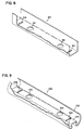
- the support section 90 includes a planar bottom portion and sides extending upward therefrom.
- Probe mounting orifices 92 are formed in the bottom portion and spaced apart for receiving sensor probes 58 .
- Slots 94 are formed near the end of the support section 90 .
- the sections 90 accommodate a clip member 44 , shown in Figure 4, to attach to sections in an end-to-end relationship. It can be appreciated that the sections 90 insert within the conduit and support the probes 50 in a spaced apart relationship and substantially vertically aligning the sensors 58 .
- the support section 100 includes an outer portion 102 and a mounting portion 104 .
- the outer portion 102 and mounting portion 104 are integrally formed of a single element but may be attached in other ways as well.
- the outer portion 102 forms an open top for receiving probes 58 mounting in orifices 106 in the upper portion of the mounting portion 104 .
- the mounting portion 104 accommodates a clip 44 , shown in Figure 4, for connecting the sections 100 in an end-to-end relationship.
- the clips 44 attach to the slots 108 in adjacent sections.
- the support section 140 includes an arcing outer portion 142 and a mounting potion 144 having slots 148 formed therein.
- the outer portion 142 forms an open top for receiving probes 58 mounting in orifices 146 in the upper portion of the mounting portion 144 .
- the mounting portion 144 accommodates the clip 44 shown in Figure 4, for connecting the sections 140 in an end-to-end relationship.
- the clips 44 attach to the slots 148 in adjacent sections with the clips 44 being inverted from the position shown in Figure 4.
- the support structure 30 and the probes 50 may be placed.
- the first section 32 is placed into the access hole 26 and placed into the opening 74 of the cradle member 70 .
- the cradle member 70 is connected via the sleeve member 72 to the remainder of the conduit 24 .
- the first sensor probe 50 is placed into a mounting hole 40 in the frame 38 and the associated wiring is fed backward toward the open end.
- the retrieval line 76 is connected to the first section and extended backward.
- the section 32 is pushed forward into the conduit until sufficient room is made in the opening 74 of the cradle 70 with the second section 32 placed so that the clip member 44 engages the slot 42 in the frame 38 of the first section 32 .
- the string of sensors is placed through the open top 36 of the second section 32 and the retrieval line 76 is also placed over the openings in the section 32 . If spacing dictates that a probe 50 should be placed in a section 32 , the probe 50 is inserted into one of the mounting holes 40 .
- the connected sections 32 are pushed forward into the conduit 24 . This process is repeated until sufficient sections 32 have been placed into the conduit 24 so that the sensor probes 50 are aligned with their predetermined sensing positions beneath the vehicle travel surface 22 .
- a cradle clip 80 is placed onto the opening 74 of the cradle member 70 and over the last section 32 .
- the cradle clip 80 includes a support section frame engaging portion 82 which fits over the frame 38 of the support section 32 .
- the cradle clip 80 also includes a support section wall engaging portion 84 which extends over the opening 36 and the curved wall 34 .
- a cradle engaging portion 86 attaches to the edge of the cradle opening 74 .
- the clip 80 secures the last section 32 into place and retains the entire support structure 30 in proper alignment and positioned at the proper distance into the conduit 24 .
- the wiring 60 is then fed to the proper processors for data analysis, which may either be placed at the hand hole 26 or placed remotely therefrom.
- FIG. 11 there is shown a second embodiment of vehicle sensing system 120 similar to the system 20 shown in Figure 1.
- the system 120 includes sensor probes 50 mounted in support sections 32 within a conduit 24 .
- intermediate connector sections 122 may be inserted in place of the selected support sections 32 .
- the connector sections 122 may be solidly attached to the sections 32 or may include a hinge 124 for connecting the connector sections 122 to the support sections 32 .
- connector sections 122 may be reduced weight and low cost shafts or struts.
- the connector sections 122 are typically clipped or otherwise detachably connected to the support sections 32 in such a manner that the distance between the sections 32 and the relative alignment of the sections 32 is maintained. In this manner, the connector sections 122 may be utilized in conjunction with the support sections to provide a low cost, light weight and simple to install and remove system 120 .
- the vehicle sensing system 130 includes support sections 32 inserted into conduit 24 .
- a single access hole 26 may be utilized for installation of the system 130 .
- connector material 132 may be utilized.
- the system 130 utilizes the connector material 132 which clips or otherwise attaches to the support sections 32 .
- the connector material 132 may be substantially stiff material which possesses some flexibility such that it may be coiled or rolled.
- the connector material 132 maintains the distance between the support sections 32 and the relative angular alignment. In this manner, support sections 32 may be clipped or otherwise attached to the connector material 132 at predetermined locations along the material 132 or supporting sensors 50 .
- the method for installation requires placement of only a single support section 32 , 90 , 100 or 140 at a time.
- the support structure 30 does not need to be pulled through and requires only a single opening 26 at one side of the vehicle travel surface 22 rather than openings at each end for pulling electronics and other structures through the hole.
- the structure provides a light weight support structure 30 which can be easily inserted.
- Each of the sections provide for no relative angular movement between adjacent sections 32 so that all of the probes 50 may be substantially vertically aligned for improved performance.
- the structure can be pulled outward through the access hole 26 by removing one section 32 at a time and pulling the sections back with the retrieval line 76 or by taking the end most section 32 and pulling it into the opening and unclipping the end most section 32 from the next adjacent section 32 .
- the distance to the endmost sensor may be measured from the access hole 26 and that sufficient support sections 32 may be inserted until the end probe 50 is placed at the proper position beneath the pavement.
- the distance back from which a sensor probe 50 needs to be placed from the first section may be marked on the retrieval line 76 or on the wiring and a probe inserted into the sections 32 proximate the predetermined position. In this manner, easy installation is provided for following placement of the first endmost probe 50 .
- the present structure provides for magneto-inductive sensing which reduces the number of false readings and provides for a more accurate reading of even smaller vehicles.
- the probes may be placed at different positions within each lane under the pavement for covering substantially the entire width of the pavement, if so desired.
- the probes 50 may be placed at a lower depth so that the pavement may be left intact, thereby reducing the number of lanes which must be closed, as well as the length of time that traffic flows is interrupted during initial installation of the system 20 .
- service or maintenance typically does not require any lane closures. This provides for substantial labor savings and decreased traffic interruption through the location where the presence of vehicles is being sensed.
- the present invention also provides for easy installation or repair of the vehicle sensing system 20 after the pavement has been laid without loss of efficiency.
Landscapes
- Life Sciences & Earth Sciences (AREA)
- Physics & Mathematics (AREA)
- Engineering & Computer Science (AREA)
- Remote Sensing (AREA)
- General Physics & Mathematics (AREA)
- Environmental & Geological Engineering (AREA)
- Geology (AREA)
- General Life Sciences & Earth Sciences (AREA)
- Geophysics (AREA)
- Electromagnetism (AREA)
- Geophysics And Detection Of Objects (AREA)
- Traffic Control Systems (AREA)
Description
Claims (11)
- A system for detecting vehicles on a vehicle travel surface, comprising:(a) a conduit for installation under the vehicle travel surface; and(b) a support section adapted to fit within the conduit, said support section arranged to carry a sensor probe at a fixed orientation relative to the support section to a predetermined position within the conduit, the support section adapted for rotation within the conduit to permit adjustment of the orientation of the sensor probe with respect to the vehicle travel surface.
- A system according to claim I, further comprising a second support section connected to said support section in an end to end manner, so that both support sections may be rotated together within the conduit.
- A system according to claim 2, wherein each support section is separable from each adjacent support section.
- A system according to claim 2, further comprising at least one clip for detachably connecting adjacent support sections to each other.
- A system according to claim 1, wherein the system further comprises a sensor probe within the support section.
- A system according to claim 5, wherein said sensor probe is wired to a remote indicator.
- A system according to claim 1, wherein the system includes a support section that is weighted to orient that support section.
- A system according to claim 1, further comprising spacers for insertion intermediate said support section and an adjacent support section for connecting the selected support sections at a fixed position relative to each other.
- A support section for a probe, comprising:(a) outer walls;(b) a receiving portion for receiving the probe;(c) a mounting portion; and(d) an attachment structure adjacent an end of the support section, the attachment structure being attachable to a like mounting portion of an adjacent support section and, when so attached, maintaining rotational alignment between adjacent support sections.
- The support section according to claim 9, wherein the mounting portion is a tab, and the attachment structure is a slot for receiving the tab.
- A support section according to claim 9, wherein the receiving portion is configured for aligning the probes toward the open top portion.
Applications Claiming Priority (3)
| Application Number | Priority Date | Filing Date | Title |
|---|---|---|---|
| US08/777,298 US5850192A (en) | 1996-12-27 | 1996-12-27 | Apparatus for sensing vehicles |
| US777298 | 1996-12-27 | ||
| PCT/US1997/006408 WO1998029765A1 (en) | 1996-12-27 | 1997-04-17 | Apparatus for sensing vehicles |
Publications (2)
| Publication Number | Publication Date |
|---|---|
| EP0950199A1 EP0950199A1 (en) | 1999-10-20 |
| EP0950199B1 true EP0950199B1 (en) | 2002-03-20 |
Family
ID=25109865
Family Applications (1)
| Application Number | Title | Priority Date | Filing Date |
|---|---|---|---|
| EP97918693A Expired - Lifetime EP0950199B1 (en) | 1996-12-27 | 1997-04-17 | Apparatus for sensing vehicles |
Country Status (10)
| Country | Link |
|---|---|
| US (1) | US5850192A (en) |
| EP (1) | EP0950199B1 (en) |
| JP (1) | JP3978467B2 (en) |
| KR (1) | KR100467303B1 (en) |
| AU (1) | AU725229B2 (en) |
| BR (1) | BR9714101B1 (en) |
| CA (1) | CA2274969C (en) |
| DE (1) | DE69711234T2 (en) |
| ES (1) | ES2170947T3 (en) |
| WO (1) | WO1998029765A1 (en) |
Families Citing this family (14)
| Publication number | Priority date | Publication date | Assignee | Title |
|---|---|---|---|---|
| US6546344B1 (en) | 1999-07-02 | 2003-04-08 | Banner Engineering Corporation | Magnetic anomaly sensor system |
| US6166660A (en) * | 1999-09-15 | 2000-12-26 | Grenier; Frank | Driveway alarm system |
| US7102244B2 (en) * | 2002-10-03 | 2006-09-05 | Hunter Jr John P | Vehicle actuated road imbedded magneto generator |
| US7005850B2 (en) * | 2003-02-20 | 2006-02-28 | Sensonix, Inc. | Magnetic sensor system and method for installing magnetic sensors |
| US6870489B2 (en) * | 2003-02-28 | 2005-03-22 | 3M Innovative Properties Company | Vehicle sensing system |
| US20040174273A1 (en) * | 2003-03-03 | 2004-09-09 | 3M Innovative Properties Company | Vehicle sensing system |
| US8028961B2 (en) | 2006-12-22 | 2011-10-04 | Central Signal, Llc | Vital solid state controller |
| EP2308035A4 (en) * | 2008-06-13 | 2011-10-19 | Tmt Services And Supplies Pty Ltd | Traffic control system and method |
| US20130063282A1 (en) | 2010-05-31 | 2013-03-14 | Central Signal, Llc | Roadway detection |
| DE102013018003B4 (en) * | 2013-11-29 | 2015-09-24 | Hermann Eser | Apparatus and method for speed measurement |
| DE102015202780A1 (en) * | 2015-02-17 | 2016-08-18 | Robert Bosch Gmbh | sensor device |
| US12579887B1 (en) | 2018-02-09 | 2026-03-17 | Applied Information, Inc. | Systems, methods, and devices for communication between traffic controller systems and mobile transmitters and receivers |
| US11069234B1 (en) | 2018-02-09 | 2021-07-20 | Applied Information, Inc. | Systems, methods, and devices for communication between traffic controller systems and mobile transmitters and receivers |
| US11205345B1 (en) | 2018-10-02 | 2021-12-21 | Applied Information, Inc. | Systems, methods, devices, and apparatuses for intelligent traffic signaling |
Family Cites Families (18)
| Publication number | Priority date | Publication date | Assignee | Title |
|---|---|---|---|---|
| US3249915A (en) * | 1965-04-20 | 1966-05-03 | Trw Inc | Method and apparatus for vehicle detection |
| US3649958A (en) * | 1970-03-25 | 1972-03-14 | Canoga Controls Corp | Vehicle detection system |
| US3714626A (en) * | 1971-03-18 | 1973-01-30 | Canoga Controls Corp | Vehicle detection system |
| US3775742A (en) * | 1972-09-18 | 1973-11-27 | Canoga Controls Corp | Vehicle detection system |
| US3943339A (en) * | 1974-04-29 | 1976-03-09 | Canoga Controls Corporation | Inductive loop detector system |
| DE2437797C3 (en) * | 1974-08-06 | 1979-04-26 | Elmeg-Elektro-Mechanik Gmbh, 3150 Peine | Arrangement for counting vehicles |
| US3984764A (en) * | 1975-03-03 | 1976-10-05 | Canoga Controls Corporation | Inductive loop structure for detecting the presence of vehicles over a roadway |
| US4032096A (en) * | 1976-03-03 | 1977-06-28 | Frederick Perrault | Curved bracket adapter |
| US4449115A (en) * | 1980-10-15 | 1984-05-15 | Minnesota Mining And Manufacturing Company | Apparatus for detecting ferromagnetic material |
| US4839480A (en) * | 1986-11-05 | 1989-06-13 | The Gates Rubber Company | Vehicle sensing device |
| US4943805A (en) * | 1986-11-13 | 1990-07-24 | Dennison James L | Conduit-enclosed induction loop for a vehicle detector |
| CH683714A5 (en) * | 1990-12-19 | 1994-04-29 | Kk Holding Ag | Force sensor arrangement, in particular for the dynamic axle load, speed, center distance and total weight determination of vehicles. |
| US5265481A (en) * | 1990-12-19 | 1993-11-30 | Kistler Instrumente Ag | Force sensor systems especially for determining dynamically the axle load, speed, wheelbase and gross weight of vehicles |
| US5442136A (en) * | 1992-07-02 | 1995-08-15 | Allen; Jerry L. | Method of installation of partitioning device for a tubular conduit |
| US5486820A (en) * | 1992-12-18 | 1996-01-23 | The Whitaker Corporation | Traffic sensor having piezoelectric sensors which distinguish lanes |
| US5491475A (en) * | 1993-03-19 | 1996-02-13 | Honeywell Inc. | Magnetometer vehicle detector |
| US5520056A (en) * | 1993-04-01 | 1996-05-28 | Etat Francais | Process for conditioning and for placing a traffic sensor |
| GB2437797A (en) * | 2006-05-05 | 2007-11-07 | Robert Stephen Scott | Flood barrier |
-
1996
- 1996-12-27 US US08/777,298 patent/US5850192A/en not_active Expired - Lifetime
-
1997
- 1997-04-17 WO PCT/US1997/006408 patent/WO1998029765A1/en not_active Ceased
- 1997-04-17 CA CA002274969A patent/CA2274969C/en not_active Expired - Lifetime
- 1997-04-17 AU AU26739/97A patent/AU725229B2/en not_active Expired
- 1997-04-17 EP EP97918693A patent/EP0950199B1/en not_active Expired - Lifetime
- 1997-04-17 KR KR10-1999-7005830A patent/KR100467303B1/en not_active Expired - Lifetime
- 1997-04-17 ES ES97918693T patent/ES2170947T3/en not_active Expired - Lifetime
- 1997-04-17 DE DE69711234T patent/DE69711234T2/en not_active Expired - Lifetime
- 1997-04-17 JP JP52995898A patent/JP3978467B2/en not_active Expired - Lifetime
- 1997-04-17 BR BRPI9714101-1A patent/BR9714101B1/en not_active IP Right Cessation
Also Published As
| Publication number | Publication date |
|---|---|
| ES2170947T3 (en) | 2002-08-16 |
| DE69711234T2 (en) | 2002-07-18 |
| AU725229B2 (en) | 2000-10-12 |
| JP2001508568A (en) | 2001-06-26 |
| KR100467303B1 (en) | 2005-01-24 |
| JP3978467B2 (en) | 2007-09-19 |
| KR20000062349A (en) | 2000-10-25 |
| CA2274969A1 (en) | 1998-07-09 |
| AU2673997A (en) | 1998-07-31 |
| WO1998029765A1 (en) | 1998-07-09 |
| BR9714101A (en) | 2000-03-21 |
| CA2274969C (en) | 2005-02-08 |
| EP0950199A1 (en) | 1999-10-20 |
| DE69711234D1 (en) | 2002-04-25 |
| BR9714101B1 (en) | 2009-05-05 |
| US5850192A (en) | 1998-12-15 |
Similar Documents
| Publication | Publication Date | Title |
|---|---|---|
| US5850192A (en) | Apparatus for sensing vehicles | |
| US6072405A (en) | Meter transmission unit for use with a pit set utility meter | |
| JP3466625B2 (en) | Positioning of independent underground boring machines | |
| KR101457649B1 (en) | System for sensing collapse of the slope | |
| US5044303A (en) | Sub-surface conduit marking apparatus | |
| US8988969B2 (en) | Detection of cross bores involving buried utilities | |
| US5320180A (en) | Dual antenna radio frequency locating apparatus and method | |
| US5660505A (en) | Silt fence anchor | |
| WO2017222271A1 (en) | System and method for rapidly detecting ground subsidence | |
| US5949373A (en) | Automated cable installation method and apparatus | |
| US7419140B2 (en) | Security fence module | |
| ES2200436T3 (en) | PROBE OF MEASUREMENT FOR WATER SUPPLY NETWORKS AND PROCEDURE FOR DETECTION OF LEAKS. | |
| US20110148420A1 (en) | Service tee marker fixture | |
| US20070120035A1 (en) | In-ground anchor structure for interchangeable posts and signs | |
| US20070044329A1 (en) | Apparatus and method for locating subterranean objects | |
| US20040178930A1 (en) | Vehicle sensing system | |
| KR100919722B1 (en) | Traffic monitoring apparatus | |
| JP2001296151A (en) | Optical fiber scour sensor and scour detection system using the same | |
| CN113235712A (en) | Mounting method of urban drainage pipe network monitoring system | |
| KR100983103B1 (en) | Magnetic Mark Fixture for Checking Pipe Lines | |
| EP2166391B1 (en) | Splice box and marking device | |
| KR100672012B1 (en) | Sewage pipe buried location map sign installation structure | |
| US20220163314A1 (en) | A ground movement monitoring system and method | |
| KR102375669B1 (en) | Underground driveway waterway icing prevention system | |
| CN113430973B (en) | High-stability electric car stopping structure and construction method of structure |
Legal Events
| Date | Code | Title | Description |
|---|---|---|---|
| PUAI | Public reference made under article 153(3) epc to a published international application that has entered the european phase |
Free format text: ORIGINAL CODE: 0009012 |
|
| 17P | Request for examination filed |
Effective date: 19990608 |
|
| AK | Designated contracting states |
Kind code of ref document: A1 Designated state(s): DE ES FR GB IT NL SE |
|
| GRAG | Despatch of communication of intention to grant |
Free format text: ORIGINAL CODE: EPIDOS AGRA |
|
| 17Q | First examination report despatched |
Effective date: 20010420 |
|
| GRAG | Despatch of communication of intention to grant |
Free format text: ORIGINAL CODE: EPIDOS AGRA |
|
| GRAG | Despatch of communication of intention to grant |
Free format text: ORIGINAL CODE: EPIDOS AGRA |
|
| GRAH | Despatch of communication of intention to grant a patent |
Free format text: ORIGINAL CODE: EPIDOS IGRA |
|
| GRAH | Despatch of communication of intention to grant a patent |
Free format text: ORIGINAL CODE: EPIDOS IGRA |
|
| REG | Reference to a national code |
Ref country code: GB Ref legal event code: IF02 |
|
| GRAA | (expected) grant |
Free format text: ORIGINAL CODE: 0009210 |
|
| AK | Designated contracting states |
Kind code of ref document: B1 Designated state(s): DE ES FR GB IT NL SE |
|
| REF | Corresponds to: |
Ref document number: 69711234 Country of ref document: DE Date of ref document: 20020425 |
|
| ET | Fr: translation filed | ||
| REG | Reference to a national code |
Ref country code: ES Ref legal event code: FG2A Ref document number: 2170947 Country of ref document: ES Kind code of ref document: T3 |
|
| PLBE | No opposition filed within time limit |
Free format text: ORIGINAL CODE: 0009261 |
|
| STAA | Information on the status of an ep patent application or granted ep patent |
Free format text: STATUS: NO OPPOSITION FILED WITHIN TIME LIMIT |
|
| 26N | No opposition filed |
Effective date: 20021223 |
|
| NLS | Nl: assignments of ep-patents |
Owner name: 3M INNOVATIVE PROPERTIES COMPANY Effective date: 20070508 Owner name: 3M COMPANY Effective date: 20070508 |
|
| REG | Reference to a national code |
Ref country code: GB Ref legal event code: 732E |
|
| REG | Reference to a national code |
Ref country code: FR Ref legal event code: TP Ref country code: FR Ref legal event code: CD |
|
| REG | Reference to a national code |
Ref country code: FR Ref legal event code: TP |
|
| REG | Reference to a national code |
Ref country code: FR Ref legal event code: PLFP Year of fee payment: 20 |
|
| PGFP | Annual fee paid to national office [announced via postgrant information from national office to epo] |
Ref country code: NL Payment date: 20160426 Year of fee payment: 20 |
|
| PGFP | Annual fee paid to national office [announced via postgrant information from national office to epo] |
Ref country code: DE Payment date: 20160427 Year of fee payment: 20 Ref country code: GB Payment date: 20160427 Year of fee payment: 20 Ref country code: ES Payment date: 20160426 Year of fee payment: 20 |
|
| PGFP | Annual fee paid to national office [announced via postgrant information from national office to epo] |
Ref country code: IT Payment date: 20160421 Year of fee payment: 20 Ref country code: FR Payment date: 20160425 Year of fee payment: 20 Ref country code: SE Payment date: 20160427 Year of fee payment: 20 |
|
| REG | Reference to a national code |
Ref country code: DE Ref legal event code: R071 Ref document number: 69711234 Country of ref document: DE |
|
| REG | Reference to a national code |
Ref country code: NL Ref legal event code: MK Effective date: 20170416 |
|
| REG | Reference to a national code |
Ref country code: GB Ref legal event code: PE20 Expiry date: 20170416 |
|
| PG25 | Lapsed in a contracting state [announced via postgrant information from national office to epo] |
Ref country code: GB Free format text: LAPSE BECAUSE OF EXPIRATION OF PROTECTION Effective date: 20170416 |
|
| REG | Reference to a national code |
Ref country code: ES Ref legal event code: FD2A Effective date: 20180508 |
|
| PG25 | Lapsed in a contracting state [announced via postgrant information from national office to epo] |
Ref country code: ES Free format text: LAPSE BECAUSE OF EXPIRATION OF PROTECTION Effective date: 20170418 |