EP0949982B1 - An improved process and apparatus for the preparation of particulate parts - Google Patents
An improved process and apparatus for the preparation of particulate parts Download PDFInfo
- Publication number
- EP0949982B1 EP0949982B1 EP97935127A EP97935127A EP0949982B1 EP 0949982 B1 EP0949982 B1 EP 0949982B1 EP 97935127 A EP97935127 A EP 97935127A EP 97935127 A EP97935127 A EP 97935127A EP 0949982 B1 EP0949982 B1 EP 0949982B1
- Authority
- EP
- European Patent Office
- Prior art keywords
- tube
- particles
- microwave
- outlet
- sintered
- Prior art date
- Legal status (The legal status is an assumption and is not a legal conclusion. Google has not performed a legal analysis and makes no representation as to the accuracy of the status listed.)
- Expired - Lifetime
Links
Images

Classifications
-
- F—MECHANICAL ENGINEERING; LIGHTING; HEATING; WEAPONS; BLASTING
- F27—FURNACES; KILNS; OVENS; RETORTS
- F27D—DETAILS OR ACCESSORIES OF FURNACES, KILNS, OVENS OR RETORTS, IN SO FAR AS THEY ARE OF KINDS OCCURRING IN MORE THAN ONE KIND OF FURNACE
- F27D99/00—Subject matter not provided for in other groups of this subclass
- F27D99/0001—Heating elements or systems
- F27D99/0006—Electric heating elements or system
-
- B—PERFORMING OPERATIONS; TRANSPORTING
- B22—CASTING; POWDER METALLURGY
- B22F—WORKING METALLIC POWDER; MANUFACTURE OF ARTICLES FROM METALLIC POWDER; MAKING METALLIC POWDER; APPARATUS OR DEVICES SPECIALLY ADAPTED FOR METALLIC POWDER
- B22F3/00—Manufacture of workpieces or articles from metallic powder characterised by the manner of compacting or sintering; Apparatus specially adapted therefor ; Presses and furnaces
- B22F3/10—Sintering only
- B22F3/105—Sintering only by using electric current other than for infrared radiant energy, laser radiation or plasma ; by ultrasonic bonding
-
- B—PERFORMING OPERATIONS; TRANSPORTING
- B22—CASTING; POWDER METALLURGY
- B22F—WORKING METALLIC POWDER; MANUFACTURE OF ARTICLES FROM METALLIC POWDER; MAKING METALLIC POWDER; APPARATUS OR DEVICES SPECIALLY ADAPTED FOR METALLIC POWDER
- B22F7/00—Manufacture of composite layers, workpieces, or articles, comprising metallic powder, by sintering the powder, with or without compacting wherein at least one part is obtained by sintering or compression
- B22F7/06—Manufacture of composite layers, workpieces, or articles, comprising metallic powder, by sintering the powder, with or without compacting wherein at least one part is obtained by sintering or compression of composite workpieces or articles from parts, e.g. to form tipped tools
-
- C—CHEMISTRY; METALLURGY
- C22—METALLURGY; FERROUS OR NON-FERROUS ALLOYS; TREATMENT OF ALLOYS OR NON-FERROUS METALS
- C22C—ALLOYS
- C22C1/00—Making non-ferrous alloys
- C22C1/04—Making non-ferrous alloys by powder metallurgy
- C22C1/05—Mixtures of metal powder with non-metallic powder
- C22C1/051—Making hard metals based on borides, carbides, nitrides, oxides or silicides; Preparation of the powder mixture used as the starting material therefor
-
- C—CHEMISTRY; METALLURGY
- C23—COATING METALLIC MATERIAL; COATING MATERIAL WITH METALLIC MATERIAL; CHEMICAL SURFACE TREATMENT; DIFFUSION TREATMENT OF METALLIC MATERIAL; COATING BY VACUUM EVAPORATION, BY SPUTTERING, BY ION IMPLANTATION OR BY CHEMICAL VAPOUR DEPOSITION, IN GENERAL; INHIBITING CORROSION OF METALLIC MATERIAL OR INCRUSTATION IN GENERAL
- C23C—COATING METALLIC MATERIAL; COATING MATERIAL WITH METALLIC MATERIAL; SURFACE TREATMENT OF METALLIC MATERIAL BY DIFFUSION INTO THE SURFACE, BY CHEMICAL CONVERSION OR SUBSTITUTION; COATING BY VACUUM EVAPORATION, BY SPUTTERING, BY ION IMPLANTATION OR BY CHEMICAL VAPOUR DEPOSITION, IN GENERAL
- C23C30/00—Coating with metallic material characterised only by the composition of the metallic material, i.e. not characterised by the coating process
- C23C30/005—Coating with metallic material characterised only by the composition of the metallic material, i.e. not characterised by the coating process on hard metal substrates
-
- F—MECHANICAL ENGINEERING; LIGHTING; HEATING; WEAPONS; BLASTING
- F27—FURNACES; KILNS; OVENS; RETORTS
- F27B—FURNACES, KILNS, OVENS OR RETORTS IN GENERAL; OPEN SINTERING OR LIKE APPARATUS
- F27B21/00—Open or uncovered sintering apparatus; Other heat-treatment apparatus of like construction
-
- F—MECHANICAL ENGINEERING; LIGHTING; HEATING; WEAPONS; BLASTING
- F27—FURNACES; KILNS; OVENS; RETORTS
- F27D—DETAILS OR ACCESSORIES OF FURNACES, KILNS, OVENS OR RETORTS, IN SO FAR AS THEY ARE OF KINDS OCCURRING IN MORE THAN ONE KIND OF FURNACE
- F27D1/00—Casings; Linings; Walls; Roofs
- F27D1/16—Making or repairing linings ; Increasing the durability of linings; Breaking away linings
-
- H—ELECTRICITY
- H05—ELECTRIC TECHNIQUES NOT OTHERWISE PROVIDED FOR
- H05B—ELECTRIC HEATING; ELECTRIC LIGHT SOURCES NOT OTHERWISE PROVIDED FOR; CIRCUIT ARRANGEMENTS FOR ELECTRIC LIGHT SOURCES, IN GENERAL
- H05B6/00—Heating by electric, magnetic or electromagnetic fields
- H05B6/64—Heating using microwaves
- H05B6/80—Apparatus for specific applications
-
- B—PERFORMING OPERATIONS; TRANSPORTING
- B22—CASTING; POWDER METALLURGY
- B22F—WORKING METALLIC POWDER; MANUFACTURE OF ARTICLES FROM METALLIC POWDER; MAKING METALLIC POWDER; APPARATUS OR DEVICES SPECIALLY ADAPTED FOR METALLIC POWDER
- B22F3/00—Manufacture of workpieces or articles from metallic powder characterised by the manner of compacting or sintering; Apparatus specially adapted therefor ; Presses and furnaces
- B22F3/10—Sintering only
- B22F3/105—Sintering only by using electric current other than for infrared radiant energy, laser radiation or plasma ; by ultrasonic bonding
- B22F2003/1054—Sintering only by using electric current other than for infrared radiant energy, laser radiation or plasma ; by ultrasonic bonding by microwave
-
- B—PERFORMING OPERATIONS; TRANSPORTING
- B22—CASTING; POWDER METALLURGY
- B22F—WORKING METALLIC POWDER; MANUFACTURE OF ARTICLES FROM METALLIC POWDER; MAKING METALLIC POWDER; APPARATUS OR DEVICES SPECIALLY ADAPTED FOR METALLIC POWDER
- B22F5/00—Manufacture of workpieces or articles from metallic powder characterised by the special shape of the product
- B22F2005/001—Cutting tools, earth boring or grinding tool other than table ware
-
- B—PERFORMING OPERATIONS; TRANSPORTING
- B22—CASTING; POWDER METALLURGY
- B22F—WORKING METALLIC POWDER; MANUFACTURE OF ARTICLES FROM METALLIC POWDER; MAKING METALLIC POWDER; APPARATUS OR DEVICES SPECIALLY ADAPTED FOR METALLIC POWDER
- B22F2999/00—Aspects linked to processes or compositions used in powder metallurgy
-
- F—MECHANICAL ENGINEERING; LIGHTING; HEATING; WEAPONS; BLASTING
- F27—FURNACES; KILNS; OVENS; RETORTS
- F27B—FURNACES, KILNS, OVENS OR RETORTS IN GENERAL; OPEN SINTERING OR LIKE APPARATUS
- F27B9/00—Furnaces through which the charge is moved mechanically, e.g. of tunnel type; Similar furnaces in which the charge moves by gravity
- F27B9/30—Details, accessories or equipment specially adapted for furnaces of these types
- F27B9/38—Arrangements of devices for charging
- F27B2009/386—Lateral intake or outtake
-
- F—MECHANICAL ENGINEERING; LIGHTING; HEATING; WEAPONS; BLASTING
- F27—FURNACES; KILNS; OVENS; RETORTS
- F27B—FURNACES, KILNS, OVENS OR RETORTS IN GENERAL; OPEN SINTERING OR LIKE APPARATUS
- F27B9/00—Furnaces through which the charge is moved mechanically, e.g. of tunnel type; Similar furnaces in which the charge moves by gravity
- F27B9/14—Furnaces through which the charge is moved mechanically, e.g. of tunnel type; Similar furnaces in which the charge moves by gravity characterised by the path of the charge during treatment; characterised by the means by which the charge is moved during treatment
- F27B9/142—Furnaces through which the charge is moved mechanically, e.g. of tunnel type; Similar furnaces in which the charge moves by gravity characterised by the path of the charge during treatment; characterised by the means by which the charge is moved during treatment the charge moving along a vertical axis
-
- F—MECHANICAL ENGINEERING; LIGHTING; HEATING; WEAPONS; BLASTING
- F27—FURNACES; KILNS; OVENS; RETORTS
- F27D—DETAILS OR ACCESSORIES OF FURNACES, KILNS, OVENS OR RETORTS, IN SO FAR AS THEY ARE OF KINDS OCCURRING IN MORE THAN ONE KIND OF FURNACE
- F27D99/00—Subject matter not provided for in other groups of this subclass
- F27D99/0001—Heating elements or systems
- F27D99/0006—Electric heating elements or system
- F27D2099/0028—Microwave heating
-
- F—MECHANICAL ENGINEERING; LIGHTING; HEATING; WEAPONS; BLASTING
- F27—FURNACES; KILNS; OVENS; RETORTS
- F27D—DETAILS OR ACCESSORIES OF FURNACES, KILNS, OVENS OR RETORTS, IN SO FAR AS THEY ARE OF KINDS OCCURRING IN MORE THAN ONE KIND OF FURNACE
- F27D3/00—Charging; Discharging; Manipulation of charge
- F27D3/04—Ram or pusher apparatus
Definitions
- Microwave heating has demonstrated itself to be a powerful technique for sintering various ceramics, especially through the past decade. Microwave heating may decrease the sintering temperatures and times dramatically, and is economically advantageous due to considerable energy savings.
- one of the major limitations is the volume and/or size of the ceramic products that can be microwave sintered because an inhomogeneous microwave energy distribution inside the applicator which often results in a non-uniform heating. Considerable research has gone into making microwave sintering technology commercially viable.
- green materials refers to those which have been provided but have not been sintered. For particulate matter, they typically have the form of powders.
- the preparation of loose material which is sintered defines small particles which can be used later in abrasive wheels and the like. Normally, these materials must be sintered to a specified grain size. In many applications, the quality or performance of the material is directly impacted by the grain size accomplished in the sintering process. In one aspect, grain size has an undesirable impact on the finished product. More specifically, this arises from the fact that additives often are placed in control quantities in the material prior to sintering so that the grain boundaries are defined by the additives. While there are additives available which do control grain size, the additives weaken or reduce the hardness of the finished product. Therefore such additives, while desirable in one aspect, are not desirable in other regards.
- grain boundary additives are material factors, thereby providing a balanced mix of properties where the properties themselves result in some kind of compromise in the design of such sintered products. Effectively, grain boundary size is controlled only at a cost in sintered particle hardness.
- the microwave applicator is designed to focus the microwave field in the central area as uniformly as possible.
- a long cylindrical ceramic hollow tube contains the unsintered (or green) material which is fed into the microwave applicator at a constant feed speed. As the green material enters the microwave cavity, it is heated and gradually sintered while passing through the microwave zone. The heating rate, sintering time and cooling rate are controlled by the input microwave power, the feeding speed, and the thermal insulation surrounding the heated material.
- the ceramic hollow tube is also rotated during processing for uniform and homogeneous heating. As the green.'material passes through the high temperature zone, the particles are sintered entirely.
- the ceramic hollow tube is moved continuously in the axial direction during the processing, there is virtually no limitation to the length or volume of the product that can be processed by this technique. Consequently, it is possible to scale up the volume of the ceramic products to be microwave sintered by this technique by implementing a continuous process.
- Sintered particles prepared by this method exhibited greater micro Vickers hardness, even as much as 1500 kg/mm 2 . better crystalline uniformity and average grain size less than sintered materials processed in the conventional manner.
- the process of the present invention uses microwave sintering to obtain higher heating rates to form better conventional products.
- microwave heat is generated internally within the material instead of originating from external heating sources and is a function of the material being processed.
- the dielectric loss begins to increase rapidly and the sintered part begins to absorb microwaves more efficiently. This also raises the temperature.
- heating rates are as high as 300°C/minute. Both batch and continuous processing systems can be employed.
- the performance of the particulates with the same hardness, toughness and density improves with decrease in grain size. It is possible to achieve very small grain sizes with high hardness, toughness and density, using the microwave processes thereby improving the characteristics when compared to the conventional process. This process requires much lower temperature (less than about 1350°C) than conventional sintering techniques (around 1500°C).
- the microwave system 10 incorporates a microwave generator 22 which forms the microwave radiation at some extremely high frequency which is conveyed by a wave guide 24 to the microwave cavity.
- the cavity is defined on the interior of an insulative sleeve 26.
- the sleeve 26 prevents heat loss through the tube 12 as will be explained.
- the microwave cavity communicates to the central area 20.
- the material is heated in a first zone 28 and reaches the maximum or sintering temperature in an intermediate zone 30.
- Zone 30 is contiguous with the zone 28.
- Zone 30 is contiguous with the zone 28.
- the sintered material is delivered through the lower end 36.
- a valve 38 is affixed at the lower end to meter the delivered product.
- the tube is open at the top end 40 and the raw ingredients are introduced through the upper end.
- the collar or clamp 14 fastens on the exterior and preferably leaves the top end 40 open for material to be added. The clamp 14 holds the tube 12 for rotation when driven by the motor 16.
- An adjacent upstanding frame 42 supports a protruding bracket 44 aligned with a bottom bracket 46.
- the brackets 44 and 46 hold a rotating screw 48 which serves as a feed screw.
- a movable carriage 50 travels up and down as driven by the screw.
- the screw 48 is rotated by the feed motor 52 shown at the lower end of the equipment. Rotation in one direction or the other causes the carriage 50 to move up or down as the case may be.
- the microwave system is provided with an adjustable power control 56 and a timer 58.
- the timer is used in batch fabrication while the system. 10 is normally simply switched on for continuous sintering. Attention is momentarily diverted to one aspect of the tube 12.
- It preferably is a dual tube construction with a tube 60 fitting snugly inside the outer tube 12. This defines an internal cavity through which the porous particulate alumina is added at the top 40. It flows along the tube; at a rate determined by the rate at which the valve 38 is operated so that the material is maintained in the hottest zone 30 for a controlled interval. For instance, the rate of flow down through the tube can be increased or decreased by throttling the flow through the valve 38. This assures that the material remains in the hottest portion 30 of the microwave cavity.
- the particles are processed as appropriate by microwave sintering.
- the microwave oven employed (equipped with a power control and a timer) produces microwave energy of 2.45 GHz frequency and power output of 900 W.
- the particulate material is placed in the closed insulating chamber, called the microwave cavity.
- the insulating material is an aluminum silicate based material.
- An inner sleeve 60 of porous zirconia is also included.
- the system reduces heat loss while maintaining high temperatures.
- a sheathed thermocouple is introduced for temperature measurement, and placed in the zone 30.
- This microwave oven procedure provides batch or continuous processing of alumina abrasive grains. For a continuous set-up, the material is added to the top of the tube 12 in the microwave field.
- Fig. 1 shows a gas supply which can optionally flood the region of heated material and force oxygen out. This may reduce the risk of oxidation.
- the starting materials came from Carborundum Universal Ltd., India. It consisted of sol-gel derived alumina grit with average particle size of about 0.6 to about 1 mm.
- the green grit is first dried at 90°C for 24 hours in an electrical dryer, and is then packed into a high purity alumina tube (30 mm in diameter and 900 mm in length) 12 which is held by a metal clamp 14 and connected to the shaft of the rotating motor 16.
- the tube 12 is inserted into the microwave applicator 18 with a middle portion located in the central area 20 of the cavity. At the beginning, the tube is stationary in the original position and is held while rotating only, without vertical feeding movement.
- Microwave power is introduced to the applicator 18 and controlled to achieve a heating rate of 50°C/min.
- the feeding motor 22 is started to feed the tube at the desired speed (about 2 mm per min.).
- the temperature of the sample is monitored by an IR pyrometer (Accufiber Inc.), and is controlled by adjusting the incident microwave power. Sintering temperature and time can be varied from 1350° to 1500C and 5 to 45 minutes respectively. Parallel experiments from conventional furnace are reported to compare the results of the two processes.
- the morphology and microstructure of the samples were characterized by SEM, the densities of the sintered samples were measured by the Archimedes method, and the Vickers hardness was measured by Micro. indentation method.
- the grit morphology of the starting and sintered particles is shown in Figure 2.
- the shape of the particles did not change, but the average particle size of the sintered sample decreased about one third because of the shrinkage during the sintering. It was expected that the particles would bind together tightly after the sintering. However, the results showed that there was no or very weak bonding between the particles.
- the particles sintered at 1500°C can be very easily separated by hand. This is important as it makes it possible to feed the green particles into the alumina tube continuously with the automatic feeder during the microwave sintering. Thus, processing of large amounts for commercial production can be achieved.
- Fig. 3 shows the micro structures of the samples processed under different sintering conditions in microwave and conventionally.
- the starting particles are the agglomerates of very fine particles with average grain size of 50-100 ⁇ m.
- the sintered samples show an obvious grain growth. The grain size grew up to about 0.2 mm after being sintered at 1400C, and about 1.0 m at 1500°C. There are some pores in the sample sintered at 1400°C. These pores disappeared at higher sintering temperature (1500°C). The density of the samples increased at the same time. Conventionally sintered samples under the identical conditions also show similar microstructure but with much higher porosity (see Figure 4).
- the quality of the microwave sintered particles mainly depends on the sintering temperature and time.
- the temperature is controlled by microwave power, and the sintering time (actually, this is the residence time of the samples in the high temperature zone) depends on the height of the high temperature zone and the feeding speed. Theoretically, higher feeding speed will lead to a higher product output, but has to be optimized for each material type to accomplish high quality products.
- the uniform high temperature zone is about 30 mm long in the microwave applicator. In this case, the residence time of the sample in the high temperature zone was about 15 minutes at a feeding speed of 2 mm/min.
- Table 1 lists properties of sintered particles processed by conventional method and in the microwave field.
- the density of the samples increased with the longer sintering time or higher sintering temperature during the microwave sintering, but the conventionally sintered samples did not exhibit any substantial change in the density after processing above 1400C. It is also noted from these results that higher abrasive index and. hardness values. were obtained in microwave sintered samples.
- Sample No. Sintering conditions Microwave Conventional VI 1450°C x 15 min. 3.70 3.92 VIII 1400°C x 45 min. 3.94 3.96 X 1500°C x 15 min. 3.96 3.89 Abrasion Index VI 95 68 VIII 100 65 X 94 94 Micro Vicker's VI 2205 732 Hardness VIII 2387 1026 (Kg/mm 2 ) X 2316 1885
Landscapes
- Engineering & Computer Science (AREA)
- Mechanical Engineering (AREA)
- Chemical & Material Sciences (AREA)
- Materials Engineering (AREA)
- General Engineering & Computer Science (AREA)
- Manufacturing & Machinery (AREA)
- Metallurgy (AREA)
- Organic Chemistry (AREA)
- Physics & Mathematics (AREA)
- Chemical Kinetics & Catalysis (AREA)
- Composite Materials (AREA)
- Electromagnetism (AREA)
- Optics & Photonics (AREA)
- Powder Metallurgy (AREA)
- Compositions Of Oxide Ceramics (AREA)
Abstract
Description
- Microwave heating has demonstrated itself to be a powerful technique for sintering various ceramics, especially through the past decade. Microwave heating may decrease the sintering temperatures and times dramatically, and is economically advantageous due to considerable energy savings. However, one of the major limitations is the volume and/or size of the ceramic products that can be microwave sintered because an inhomogeneous microwave energy distribution inside the applicator which often results in a non-uniform heating. Considerable research has gone into making microwave sintering technology commercially viable.
- In all instances, it will be described so that the sintering process begins or acts on what are known as green materials. The term green materials refers to those which have been provided but have not been sintered. For particulate matter, they typically have the form of powders.
- The preparation of loose material which is sintered defines small particles which can be used later in abrasive wheels and the like. Normally, these materials must be sintered to a specified grain size. In many applications, the quality or performance of the material is directly impacted by the grain size accomplished in the sintering process. In one aspect, grain size has an undesirable impact on the finished product. More specifically, this arises from the fact that additives often are placed in control quantities in the material prior to sintering so that the grain boundaries are defined by the additives. While there are additives available which do control grain size, the additives weaken or reduce the hardness of the finished product. Therefore such additives, while desirable in one aspect, are not desirable in other regards. The amount, nature, and dispersal of such grain boundary additives is a material factor, thereby providing a balanced mix of properties where the properties themselves result in some kind of compromise in the design of such sintered products. Effectively, grain boundary size is controlled only at a cost in sintered particle hardness.
- Continuous microwave sintering of alumina in a rotary tube furnace is known from US 5 653 775.
- Continuous microwave sintering of alumina is newly developed. One aspect of the continuous microwave sintering furnace is shown in Figure 1. The microwave applicator is designed to focus the microwave field in the central area as uniformly as possible. A long cylindrical ceramic hollow tube contains the unsintered (or green) material which is fed into the microwave applicator at a constant feed speed. As the green material enters the microwave cavity, it is heated and gradually sintered while passing through the microwave zone. The heating rate, sintering time and cooling rate are controlled by the input microwave power, the feeding speed, and the thermal insulation surrounding the heated material. The ceramic hollow tube is also rotated during processing for uniform and homogeneous heating. As the green.'material passes through the high temperature zone, the particles are sintered entirely. Since the ceramic hollow tube is moved continuously in the axial direction during the processing, there is virtually no limitation to the length or volume of the product that can be processed by this technique. Consequently, it is possible to scale up the volume of the ceramic products to be microwave sintered by this technique by implementing a continuous process.
- This disclosure proves the continuous microwave sintering technique for small or large quantities of green material. The results show better physical properties than the conventionally, processed material in respect of a loose, unconsolidated particulate product, generally referred to below as sintered particles,
- Sintered particles prepared by this method exhibited greater micro Vickers hardness, even as much as 1500 kg/mm2. better crystalline uniformity and average grain size less than sintered materials processed in the conventional manner.
- The process of the present invention uses microwave sintering to obtain higher heating rates to form better conventional products. In the process of the invention, microwave heat is generated internally within the material instead of originating from external heating sources and is a function of the material being processed. As temperature increases above a point, the dielectric loss begins to increase rapidly and the sintered part begins to absorb microwaves more efficiently. This also raises the temperature. Hence, heating rates are as high as 300°C/minute. Both batch and continuous processing systems can be employed.
- As a rule of thumb, the performance of the particulates with the same hardness, toughness and density improves with decrease in grain size. It is possible to achieve very small grain sizes with high hardness, toughness and density, using the microwave processes thereby improving the characteristics when compared to the conventional process. This process requires much lower temperature (less than about 1350°C) than conventional sintering techniques (around 1500°C).
- So that the manner in which the above recited features, advantages an objects of the present invention are attained and can be understood in detail, more particular description of the invention, briefly summarized above, ma be. had by reference to the embodiments thereof which are illustrated in th appended drawings.
- It is to be noted, however, that the appended drawings illustrate onl typical embodiments of this invention and are therefore not to be considere limiting of its scope, for the invention may admit to other equally effective embodiments.
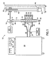
- Fig. 1 is a system drawing of a microwave oven arrangement for reduced temperature sintering;
- Fig. 2 shows a microwave sintered alumina grit in a microphotograph; and
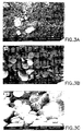
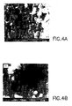
- Figs. 3 and 4 show different microwave sintered grit processed with different conditions.
-
- Going over the apparatus in Fig. 1 in some detail, the
microwave system 10 incorporates amicrowave generator 22 which forms the microwave radiation at some extremely high frequency which is conveyed by awave guide 24 to the microwave cavity. The cavity is defined on the interior of aninsulative sleeve 26. Thesleeve 26 prevents heat loss through thetube 12 as will be explained. The microwave cavity communicates to thecentral area 20. In the central area, the material is heated in a first zone 28 and reaches the maximum or sintering temperature in an intermediate zone 30. Zone 30 is contiguous with the zone 28. As the product moves downwardly, it enters into the zone 32 where cooling begins. There is adischarge zone 34 at the lower end. The sintered material is delivered through thelower end 36. For the sake of controlling the flow rate, avalve 38 is affixed at the lower end to meter the delivered product. At the upper end, the tube is open at thetop end 40 and the raw ingredients are introduced through the upper end. The collar or clamp 14 fastens on the exterior and preferably leaves thetop end 40 open for material to be added. The clamp 14 holds thetube 12 for rotation when driven by themotor 16. - An adjacent
upstanding frame 42 supports a protrudingbracket 44 aligned with abottom bracket 46. Thebrackets screw 48 which serves as a feed screw. Amovable carriage 50 travels up and down as driven by the screw. Thescrew 48 is rotated by thefeed motor 52 shown at the lower end of the equipment. Rotation in one direction or the other causes thecarriage 50 to move up or down as the case may be. - The microwave system is provided with an
adjustable power control 56 and atimer 58. The timer is used in batch fabrication while the system. 10 is normally simply switched on for continuous sintering. Attention is momentarily diverted to one aspect of thetube 12. It preferably is a dual tube construction with atube 60 fitting snugly inside theouter tube 12. This defines an internal cavity through which the porous particulate alumina is added at the top 40. It flows along the tube; at a rate determined by the rate at which thevalve 38 is operated so that the material is maintained in the hottest zone 30 for a controlled interval. For instance, the rate of flow down through the tube can be increased or decreased by throttling the flow through thevalve 38. This assures that the material remains in the hottest portion 30 of the microwave cavity. By rotating the tube continuously and continuing a feed through thetube 12 which causes gradual downward linear motion, the particles are processed as appropriate by microwave sintering. By rotating without feeding thetube 12 through thecavity 20, but with controlled particulate flow through thetube 12 andvalve 38, continuous sintering of a controlled flow can be done. - The microwave oven employed (equipped with a power control and a timer) produces microwave energy of 2.45 GHz frequency and power output of 900 W. The particulate material is placed in the closed insulating chamber, called the microwave cavity. The insulating material is an aluminum silicate based material. An
inner sleeve 60 of porous zirconia is also included. The system reduces heat loss while maintaining high temperatures. A sheathed thermocouple is introduced for temperature measurement, and placed in the zone 30. This microwave oven procedure provides batch or continuous processing of alumina abrasive grains. For a continuous set-up, the material is added to the top of thetube 12 in the microwave field. The material for sintering is continuously fed from the top and sintered grains are drained at the bottom of the tube at a controlled rate. Fig. 1 shows a gas supply which can optionally flood the region of heated material and force oxygen out. This may reduce the risk of oxidation. - The particulate manufacturing process is set out in the examples given below which are provided by way of illustration only and should not be construed to limit the scope of this present invention.
- The starting materials came from Carborundum Universal Ltd., India. It consisted of sol-gel derived alumina grit with average particle size of about 0.6 to about 1 mm. The green grit is first dried at 90°C for 24 hours in an electrical dryer, and is then packed into a high purity alumina tube (30 mm in diameter and 900 mm in length) 12 which is held by a metal clamp 14 and connected to the shaft of the
rotating motor 16. Thetube 12 is inserted into themicrowave applicator 18 with a middle portion located in thecentral area 20 of the cavity. At the beginning, the tube is stationary in the original position and is held while rotating only, without vertical feeding movement. Microwave power is introduced to theapplicator 18 and controlled to achieve a heating rate of 50°C/min. When the sample temperature reaches the set temperature, the feedingmotor 22 is started to feed the tube at the desired speed (about 2 mm per min.). The temperature of the sample is monitored by an IR pyrometer (Accufiber Inc.), and is controlled by adjusting the incident microwave power. Sintering temperature and time can be varied from 1350° to 1500C and 5 to 45 minutes respectively. Parallel experiments from conventional furnace are reported to compare the results of the two processes. - The morphology and microstructure of the samples were characterized by SEM, the densities of the sintered samples were measured by the Archimedes method, and the Vickers hardness was measured by Micro. indentation method.
- The grit morphology of the starting and sintered particles is shown in Figure 2. The shape of the particles did not change, but the average particle size of the sintered sample decreased about one third because of the shrinkage during the sintering. It was expected that the particles would bind together tightly after the sintering. However, the results showed that there was no or very weak bonding between the particles. The particles sintered at 1500°C can be very easily separated by hand. This is important as it makes it possible to feed the green particles into the alumina tube continuously with the automatic feeder during the microwave sintering. Thus, processing of large amounts for commercial production can be achieved.
- Fig. 3 shows the micro structures of the samples processed under different sintering conditions in microwave and conventionally. The starting particles are the agglomerates of very fine particles with average grain size of 50-100 µm. The sintered samples show an obvious grain growth. The grain size grew up to about 0.2 mm after being sintered at 1400C, and about 1.0 m at 1500°C. There are some pores in the sample sintered at 1400°C. These pores disappeared at higher sintering temperature (1500°C). The density of the samples increased at the same time. Conventionally sintered samples under the identical conditions also show similar microstructure but with much higher porosity (see Figure 4).
- The quality of the microwave sintered particles mainly depends on the sintering temperature and time. During the continuous microwave sintering processing, the temperature is controlled by microwave power, and the sintering time (actually, this is the residence time of the samples in the high temperature zone) depends on the height of the high temperature zone and the feeding speed. Theoretically, higher feeding speed will lead to a higher product output, but has to be optimized for each material type to accomplish high quality products. The uniform high temperature zone is about 30 mm long in the microwave applicator. In this case, the residence time of the sample in the high temperature zone was about 15 minutes at a feeding speed of 2 mm/min.
- Table 1 lists properties of sintered particles processed by conventional method and in the microwave field. The density of the samples increased with the longer sintering time or higher sintering temperature during the microwave sintering, but the conventionally sintered samples did not exhibit any substantial change in the density after processing above 1400C. It is also noted from these results that higher abrasive index and. hardness values. were obtained in microwave sintered samples.
Sample No. Sintering conditions Microwave Conventional VI 1450°C x 15 min. 3.70 3.92 VIII 1400°C x 45 min. 3.94 3.96 X 1500°C x 15 min. 3.96 3.89 Abrasion Index VI 95 68 VIII 100 65 X 94 94 Micro Vicker's VI 2205 732 Hardness VIII 2387 1026 (Kg/mm2) X 2316 1885
Claims (4)
- A method of preparing sintered particles comprising the steps of:so that the particles pass sequentially through a first zone (28) where they are heated up by the microwave radiation, an intermediate zone (30) where they reach maximum temperature and are sintered by the continued application of the microwave radiation, and a further zone (32) where cooling occurs before passing to the outlet for discharge.a) putting green particles into an elongate hollow tube (12,60) which has an inlet (at 40), an outlet (at 36) and an axial passage therebetween to enable flow of particles from the inlet to the outlet, and which has a region between the inlet and the outlet which is surrounded by an insulated sleeve (26);b) directing microwave radiation into the region of the tube surrounded by the sleeve (26);c) rotating the tube about its axis; andd) moving the particles along the tube (12,60) relative to the microwave radiation by controllably discharging sintered particles from the outlet
- A method according to claim 1 including the further step of moving the tube (12,60) linearly with respect to the sleeve (26) and the microwave radiation.
- Apparatus for sintering loose particles comprising:a) a microwave generator (22) coupled by a waveguide (24) to a heating zone (20) defined within an insulated sleeve (26);b) an elongate tube (12,60) of a microwave radiation transmitting material, at least part of which lies within the heating zone (20), the tube having an inlet (at 40) for admitting green particles and an outlet (at 36) for discharge of said particles after sintering in the heated zone (20);c) means (16) for rotating the tube within the heating zone; andd) a control valve (38) connected to the outlet to control flow of sintered particles from the tube (12,60) so as to cause particles to move along the tube yet assure adequate exposure of the green particles to the microwave radiation in the heating zone (20).
- Apparatus according to claim 3 including means (48,50,52) for moving the tube (12,60) linearly with respect to the sleeve (26).
Applications Claiming Priority (3)
| Application Number | Priority Date | Filing Date | Title |
|---|---|---|---|
| US08/687,870 US6004505A (en) | 1996-07-26 | 1996-07-26 | Process and apparatus for the preparation of particulate or solid parts |
| US687870 | 1996-07-26 | ||
| PCT/US1997/013136 WO1998004373A1 (en) | 1996-07-26 | 1997-07-25 | An improved process and apparatus for the preparation of particulate or solid parts |
Publications (3)
| Publication Number | Publication Date |
|---|---|
| EP0949982A1 EP0949982A1 (en) | 1999-10-20 |
| EP0949982A4 EP0949982A4 (en) | 2003-10-01 |
| EP0949982B1 true EP0949982B1 (en) | 2005-03-23 |
Family
ID=24762215
Family Applications (1)
| Application Number | Title | Priority Date | Filing Date |
|---|---|---|---|
| EP97935127A Expired - Lifetime EP0949982B1 (en) | 1996-07-26 | 1997-07-25 | An improved process and apparatus for the preparation of particulate parts |
Country Status (4)
| Country | Link |
|---|---|
| US (2) | US6004505A (en) |
| EP (1) | EP0949982B1 (en) |
| DE (1) | DE69732856T2 (en) |
| WO (1) | WO1998004373A1 (en) |
Families Citing this family (40)
| Publication number | Priority date | Publication date | Assignee | Title |
|---|---|---|---|---|
| US6063333A (en) | 1996-10-15 | 2000-05-16 | Penn State Research Foundation | Method and apparatus for fabrication of cobalt alloy composite inserts |
| SE9802519D0 (en) | 1998-07-13 | 1998-07-13 | Sandvik Ab | Method of making cemented carbide |
| US6325839B1 (en) | 1999-07-23 | 2001-12-04 | Jeneric/Pentron, Inc. | Method for manufacturing dental restorations |
| US6365885B1 (en) | 1999-10-18 | 2002-04-02 | The Penn State Research Foundation | Microwave processing in pure H fields and pure E fields |
| US20020106611A1 (en) * | 2001-01-19 | 2002-08-08 | Sutapa Bhaduri | Metal part having a dense core and porous periphery, biocompatible prosthesis and microwave sintering |
| US6562418B2 (en) * | 2001-05-14 | 2003-05-13 | Bwxt Y-12 Llc | Microwave processing of pressed boron powders for use as cathodes in vacuum arc sources |
| CA2409433A1 (en) * | 2002-10-23 | 2004-04-23 | Consolidated Civil Enforcement Inc. | Method of cryogenic treatment of tungsten carbide containing cobalt |
| US20040238794A1 (en) * | 2003-05-30 | 2004-12-02 | Karandikar Prashant G. | Microwave processing of composite bodies made by an infiltration route |
| US20050249627A1 (en) * | 2003-08-08 | 2005-11-10 | Jenn-Shing Wang | Manufacturing process using microwave for thermal debinding |
| US20060084566A1 (en) * | 2004-10-19 | 2006-04-20 | General Electric Company | Multiphase ceramic nanocomposites and method of making them |
| US20060251536A1 (en) * | 2005-05-05 | 2006-11-09 | General Electric Company | Microwave processing of mim preforms |
| US20060269436A1 (en) * | 2005-05-31 | 2006-11-30 | Cabot Corporation | Process for heat treating metal powder and products made from the same |
| US20070107216A1 (en) * | 2005-10-31 | 2007-05-17 | General Electric Company | Mim method for coating turbine shroud |
| US20070151769A1 (en) * | 2005-11-23 | 2007-07-05 | Smith International, Inc. | Microwave sintering |
| US20070141272A1 (en) * | 2005-12-19 | 2007-06-21 | General Electric Company | Methods and apparatus for coating gas turbine components |
| US7510032B2 (en) * | 2006-03-31 | 2009-03-31 | Kennametal Inc. | Hard composite cutting insert and method of making the same |
| US7541561B2 (en) * | 2006-09-01 | 2009-06-02 | General Electric Company | Process of microwave heating of powder materials |
| US7326892B1 (en) | 2006-09-21 | 2008-02-05 | General Electric Company | Process of microwave brazing with powder materials |
| US20080114468A1 (en) * | 2006-11-10 | 2008-05-15 | Biomet Manufacturing Corp. | Processes for making ceramic medical devices |
| US7775416B2 (en) * | 2006-11-30 | 2010-08-17 | General Electric Company | Microwave brazing process |
| US20080138533A1 (en) * | 2006-12-12 | 2008-06-12 | General Electric Company | Microwave process for forming a coating |
| US8574686B2 (en) * | 2006-12-15 | 2013-11-05 | General Electric Company | Microwave brazing process for forming coatings |
| US7946467B2 (en) * | 2006-12-15 | 2011-05-24 | General Electric Company | Braze material and processes for making and using |
| US8409318B2 (en) * | 2006-12-15 | 2013-04-02 | General Electric Company | Process and apparatus for forming wire from powder materials |
| GB0713876D0 (en) * | 2007-07-18 | 2007-08-29 | 3M Innovative Properties Co | Manufacture of components for medicinal dispensers |
| US20090139607A1 (en) * | 2007-10-28 | 2009-06-04 | General Electric Company | Braze compositions and methods of use |
| DE102008012578C5 (en) * | 2008-03-05 | 2022-04-07 | Ivoclar Vivadent Ag | dental furnace |
| US10260811B2 (en) | 2008-03-05 | 2019-04-16 | Ivoclar Vivadent Ag | Dental furnace |
| WO2010006064A2 (en) * | 2008-07-08 | 2010-01-14 | Smith International, Inc. | Pulsed electrical field assisted or spark plasma sintered polycrystalline ultra hard material and thermally stable ultra hard material cutting elements and compacts and methods of forming the same |
| US8349040B2 (en) * | 2008-07-08 | 2013-01-08 | Smith International, Inc. | Method for making composite abrasive compacts |
| US8602133B2 (en) | 2010-06-03 | 2013-12-10 | Dennis Tool Company | Tool with welded cemented metal carbide inserts welded to steel and/or cemented metal carbide |
| US20130182982A1 (en) | 2012-01-17 | 2013-07-18 | Dennis Tool Company | Carbide wear surface and method of manufacture |
| CN102601373B (en) * | 2012-04-01 | 2014-04-16 | 中国矿业大学 | Method and device for preparing composite ceramic layer surface strengthened aluminum alloy material |
| CN103880460B (en) * | 2014-02-26 | 2016-04-13 | 中原工学院 | A kind of method preparing polycrystalline diamond sintered body |
| CN106457474A (en) | 2014-06-20 | 2017-02-22 | 哈利伯顿能源服务公司 | Laser-leached polycrystalline diamond and laser-leaching methods and devices |
| CN105170981B (en) * | 2015-10-12 | 2017-07-04 | 福州大学 | A kind of microwave hot-press sintering and brazing device and its application method |
| RU2699761C1 (en) * | 2018-09-06 | 2019-09-10 | Денис Эрнестович Львов | Method of making a part from powder |
| CN109300757B (en) * | 2018-11-22 | 2023-07-18 | 中国科学院空间应用工程与技术中心 | Microwave ECR plasma cathode ring beam electron gun and 3D printing method |
| WO2022040290A1 (en) * | 2020-08-18 | 2022-02-24 | Metallum3D, Inc. | Apparatus and methods for non-resonant microwave thermal processing |
| KR102851677B1 (en) * | 2024-02-22 | 2025-08-29 | 더 썰틴 리서치 인스티튜트 오브 차이나 일렉트로닉스 테크놀로지 그룹 코포레이션 | Microwave heating chamber |
Family Cites Families (13)
| Publication number | Priority date | Publication date | Assignee | Title |
|---|---|---|---|---|
| US3261959A (en) * | 1962-02-20 | 1966-07-19 | F H Peavey & Company | Apparatus for treatment of ore |
| JPS5925902A (en) * | 1982-07-31 | 1984-02-10 | Sumitomo Electric Ind Ltd | Sintering method |
| DE3769480D1 (en) * | 1986-01-16 | 1991-05-29 | Micro Denshi Co Ltd | MICROWAVE HEATING DEVICE. |
| EP0329338A3 (en) * | 1988-02-16 | 1990-08-01 | Alcan International Limited | Process and apparatus for heating bodies at high temperature and pressure utilizing microwave energy |
| US4938673A (en) * | 1989-01-17 | 1990-07-03 | Adrian Donald J | Isostatic pressing with microwave heating and method for same |
| US5131992A (en) * | 1990-01-08 | 1992-07-21 | The United States Of America, As Represented By The Secretary Of The Interior | Microwave induced plasma process for producing tungsten carbide |
| US5013694A (en) * | 1990-04-20 | 1991-05-07 | Martin Marietta Energy Systems, Inc. | Titanium diboride-chromium diboride-yttrium titanium oxide ceramic composition and a process for making the same |
| FR2673936B1 (en) * | 1991-03-14 | 1993-12-24 | Snecma | INSTALLATION FOR HEAT TREATMENT OF PARTS OF COMPOSITE MATERIAL WITH CERAMIC MATRIX, HEATED BY MICROWAVE WAVES AND METHOD OF IMPLEMENTING SAME. |
| US5184286A (en) * | 1992-03-18 | 1993-02-02 | Martin Marietta Energy Systems, Inc. | Process for manufacturing tantalum capacitors |
| US5330942A (en) * | 1993-01-22 | 1994-07-19 | Martin Marietta Energy Systems, Inc. | Composite of refractory material |
| US5397530A (en) * | 1993-04-26 | 1995-03-14 | Hoeganaes Corporation | Methods and apparatus for heating metal powders |
| US5622905A (en) * | 1993-06-30 | 1997-04-22 | Sumitomo Electric Industries, Ltd. | Silicon nitride based sintered body |
| US5653775A (en) * | 1996-01-26 | 1997-08-05 | Minnesota Mining And Manufacturing Company | Microwave sintering of sol-gel derived abrasive grain |
-
1996
- 1996-07-26 US US08/687,870 patent/US6004505A/en not_active Expired - Lifetime
-
1997
- 1997-07-25 EP EP97935127A patent/EP0949982B1/en not_active Expired - Lifetime
- 1997-07-25 DE DE69732856T patent/DE69732856T2/en not_active Expired - Lifetime
- 1997-07-25 WO PCT/US1997/013136 patent/WO1998004373A1/en not_active Ceased
-
1999
- 1999-05-21 US US09/316,346 patent/US6126895A/en not_active Expired - Lifetime
Also Published As
| Publication number | Publication date |
|---|---|
| US6004505A (en) | 1999-12-21 |
| DE69732856D1 (en) | 2005-04-28 |
| DE69732856T2 (en) | 2006-01-26 |
| WO1998004373A1 (en) | 1998-02-05 |
| EP0949982A1 (en) | 1999-10-20 |
| EP0949982A4 (en) | 2003-10-01 |
| US6126895A (en) | 2000-10-03 |
Similar Documents
| Publication | Publication Date | Title |
|---|---|---|
| US5858037A (en) | Process for the preparation of alumina abrasives | |
| DE69732856T2 (en) | IMPROVED METHOD AND DEVICE FOR PRODUCING PARTICULATE BODIES | |
| CN115279863B (en) | Method for producing abrasive grains | |
| US5736092A (en) | Microwave sintering process | |
| US6512216B2 (en) | Microwave processing using highly microwave absorbing powdered material layers | |
| US4723996A (en) | Method and device for producing refractory materials by induction | |
| WO1998004373A9 (en) | An improved process and apparatus for the preparation of particulate or solid parts | |
| KR101994140B1 (en) | Glaze composition for high hardness glaze layer and manufacturing method of ceramic floor tile having excellent scratch resistance using the composition | |
| US4731207A (en) | Method for manufacture of high-frequency dielectric ceramics | |
| CN109760173B (en) | Laser Melting Forming Method of Wall Al2O3-GdAlO3-ZrO2 Ternary Eutectic Ceramics | |
| US9533909B2 (en) | Methods and apparatus for material processing using atmospheric thermal plasma reactor | |
| US6104015A (en) | Continuous microwave rotary furnace for processing sintered ceramics | |
| CN109761587A (en) | It is a kind of to prepare Al2O3-GdAlO3-ZrO2The method of ternary eutectic ceramics | |
| JPS62100412A (en) | Production of alumina-zirconia compound powder body | |
| JP4798372B2 (en) | Magnetic field forming apparatus, ferrite magnet manufacturing method, mold | |
| US4116598A (en) | Apparatus for producing high-melting-metal-oxide-based crystalline materials | |
| RU2222505C1 (en) | Method of production of articles from sintered glass crystalline material of lithium-alumo- silicate composition | |
| CN111517785B (en) | Production process and production equipment of high-zirconium fusion cast brick | |
| JPH0261762B2 (en) | ||
| Cherradi et al. | Microwave sintering of the high-superconductor Y-Ba-Cu-O | |
| Cheng et al. | Continuous microwave sintering of ceramics | |
| JP2003171181A (en) | Method and apparatus for manufacturing powder | |
| Werstler | Microwave Sintering of Machining Inserts | |
| CN119683999A (en) | Conductive ceramic heating base and preparation method thereof | |
| Feng et al. | ZrO2+ 3 MOL% Y2O3 CERAMIC POWDER |
Legal Events
| Date | Code | Title | Description |
|---|---|---|---|
| PUAI | Public reference made under article 153(3) epc to a published international application that has entered the european phase |
Free format text: ORIGINAL CODE: 0009012 |
|
| 17P | Request for examination filed |
Effective date: 19990225 |
|
| AK | Designated contracting states |
Kind code of ref document: A1 Designated state(s): BE DE FR GB IE IT SE |
|
| RIN1 | Information on inventor provided before grant (corrected) |
Inventor name: GIGIL, PAUL D. Inventor name: DENNIS, MAHLON Inventor name: CHENG, JIPING Inventor name: AGRAWAL, DINESH 207 MATERIALS RESEARCH LAB. Inventor name: ROY, RUSTUM |
|
| RIC1 | Information provided on ipc code assigned before grant |
Ipc: 7F 27D 23/00 B Ipc: 7B 22F 3/105 B Ipc: 7F 27B 21/00 B Ipc: 7H 05B 6/78 B Ipc: 7F 27D 1/16 B Ipc: 7C 23C 30/00 B Ipc: 7C 22C 1/05 B Ipc: 7B 22F 3/12 A |
|
| A4 | Supplementary search report drawn up and despatched |
Effective date: 20030820 |
|
| 17Q | First examination report despatched |
Effective date: 20031114 |
|
| GRAP | Despatch of communication of intention to grant a patent |
Free format text: ORIGINAL CODE: EPIDOSNIGR1 |
|
| RTI1 | Title (correction) |
Free format text: AN IMPROVED PROCESS AND APPARATUS FOR THE PREPARATION OF PARTICULATE PARTS |
|
| GRAS | Grant fee paid |
Free format text: ORIGINAL CODE: EPIDOSNIGR3 |
|
| GRAA | (expected) grant |
Free format text: ORIGINAL CODE: 0009210 |
|
| AK | Designated contracting states |
Kind code of ref document: B1 Designated state(s): BE DE FR GB IE IT SE |
|
| REG | Reference to a national code |
Ref country code: GB Ref legal event code: FG4D |
|
| REG | Reference to a national code |
Ref country code: IE Ref legal event code: FG4D |
|
| REF | Corresponds to: |
Ref document number: 69732856 Country of ref document: DE Date of ref document: 20050428 Kind code of ref document: P |
|
| REG | Reference to a national code |
Ref country code: SE Ref legal event code: TRGR |
|
| PLBE | No opposition filed within time limit |
Free format text: ORIGINAL CODE: 0009261 |
|
| STAA | Information on the status of an ep patent application or granted ep patent |
Free format text: STATUS: NO OPPOSITION FILED WITHIN TIME LIMIT |
|
| 26N | No opposition filed |
Effective date: 20051227 |
|
| ET | Fr: translation filed | ||
| REG | Reference to a national code |
Ref country code: GB Ref legal event code: 732E Free format text: REGISTERED BETWEEN 20090402 AND 20090408 |
|
| REG | Reference to a national code |
Ref country code: FR Ref legal event code: TQ |
|
| REG | Reference to a national code |
Ref country code: FR Ref legal event code: PLFP Year of fee payment: 19 |
|
| PGFP | Annual fee paid to national office [announced via postgrant information from national office to epo] |
Ref country code: IE Payment date: 20150729 Year of fee payment: 19 Ref country code: GB Payment date: 20150727 Year of fee payment: 19 Ref country code: DE Payment date: 20150729 Year of fee payment: 19 |
|
| PGFP | Annual fee paid to national office [announced via postgrant information from national office to epo] |
Ref country code: FR Payment date: 20150717 Year of fee payment: 19 Ref country code: BE Payment date: 20150727 Year of fee payment: 19 |
|
| PGFP | Annual fee paid to national office [announced via postgrant information from national office to epo] |
Ref country code: IT Payment date: 20150727 Year of fee payment: 19 |
|
| PGFP | Annual fee paid to national office [announced via postgrant information from national office to epo] |
Ref country code: SE Payment date: 20160727 Year of fee payment: 20 |
|
| PG25 | Lapsed in a contracting state [announced via postgrant information from national office to epo] |
Ref country code: BE Free format text: LAPSE BECAUSE OF NON-PAYMENT OF DUE FEES Effective date: 20160731 |
|
| REG | Reference to a national code |
Ref country code: DE Ref legal event code: R119 Ref document number: 69732856 Country of ref document: DE |
|
| GBPC | Gb: european patent ceased through non-payment of renewal fee |
Effective date: 20160725 |
|
| PG25 | Lapsed in a contracting state [announced via postgrant information from national office to epo] |
Ref country code: FR Free format text: LAPSE BECAUSE OF NON-PAYMENT OF DUE FEES Effective date: 20160801 Ref country code: DE Free format text: LAPSE BECAUSE OF NON-PAYMENT OF DUE FEES Effective date: 20170201 |
|
| REG | Reference to a national code |
Ref country code: FR Ref legal event code: ST Effective date: 20170331 |
|
| REG | Reference to a national code |
Ref country code: IE Ref legal event code: MM4A |
|
| PG25 | Lapsed in a contracting state [announced via postgrant information from national office to epo] |
Ref country code: GB Free format text: LAPSE BECAUSE OF NON-PAYMENT OF DUE FEES Effective date: 20160725 |
|
| PG25 | Lapsed in a contracting state [announced via postgrant information from national office to epo] |
Ref country code: IE Free format text: LAPSE BECAUSE OF NON-PAYMENT OF DUE FEES Effective date: 20160725 |
|
| PG25 | Lapsed in a contracting state [announced via postgrant information from national office to epo] |
Ref country code: IT Free format text: LAPSE BECAUSE OF NON-PAYMENT OF DUE FEES Effective date: 20160725 |