EP0949697A1 - Battery container - Google Patents
Battery container Download PDFInfo
- Publication number
- EP0949697A1 EP0949697A1 EP99106033A EP99106033A EP0949697A1 EP 0949697 A1 EP0949697 A1 EP 0949697A1 EP 99106033 A EP99106033 A EP 99106033A EP 99106033 A EP99106033 A EP 99106033A EP 0949697 A1 EP0949697 A1 EP 0949697A1
- Authority
- EP
- European Patent Office
- Prior art keywords
- container
- lid
- apertures
- sides
- openings
- Prior art date
- Legal status (The legal status is an assumption and is not a legal conclusion. Google has not performed a legal analysis and makes no representation as to the accuracy of the status listed.)
- Granted
Links
Images

Classifications
-
- H—ELECTRICITY
- H01—ELECTRIC ELEMENTS
- H01M—PROCESSES OR MEANS, e.g. BATTERIES, FOR THE DIRECT CONVERSION OF CHEMICAL ENERGY INTO ELECTRICAL ENERGY
- H01M50/00—Constructional details or processes of manufacture of the non-active parts of electrochemical cells other than fuel cells, e.g. hybrid cells
- H01M50/30—Arrangements for facilitating escape of gases
-
- H—ELECTRICITY
- H01—ELECTRIC ELEMENTS
- H01M—PROCESSES OR MEANS, e.g. BATTERIES, FOR THE DIRECT CONVERSION OF CHEMICAL ENERGY INTO ELECTRICAL ENERGY
- H01M50/00—Constructional details or processes of manufacture of the non-active parts of electrochemical cells other than fuel cells, e.g. hybrid cells
- H01M50/20—Mountings; Secondary casings or frames; Racks, modules or packs; Suspension devices; Shock absorbers; Transport or carrying devices; Holders
- H01M50/204—Racks, modules or packs for multiple batteries or multiple cells
- H01M50/207—Racks, modules or packs for multiple batteries or multiple cells characterised by their shape
- H01M50/209—Racks, modules or packs for multiple batteries or multiple cells characterised by their shape adapted for prismatic or rectangular cells
-
- H—ELECTRICITY
- H01—ELECTRIC ELEMENTS
- H01M—PROCESSES OR MEANS, e.g. BATTERIES, FOR THE DIRECT CONVERSION OF CHEMICAL ENERGY INTO ELECTRICAL ENERGY
- H01M50/00—Constructional details or processes of manufacture of the non-active parts of electrochemical cells other than fuel cells, e.g. hybrid cells
- H01M50/20—Mountings; Secondary casings or frames; Racks, modules or packs; Suspension devices; Shock absorbers; Transport or carrying devices; Holders
- H01M50/233—Mountings; Secondary casings or frames; Racks, modules or packs; Suspension devices; Shock absorbers; Transport or carrying devices; Holders characterised by physical properties of casings or racks, e.g. dimensions
- H01M50/24—Mountings; Secondary casings or frames; Racks, modules or packs; Suspension devices; Shock absorbers; Transport or carrying devices; Holders characterised by physical properties of casings or racks, e.g. dimensions adapted for protecting batteries from their environment, e.g. from corrosion
-
- H—ELECTRICITY
- H01—ELECTRIC ELEMENTS
- H01M—PROCESSES OR MEANS, e.g. BATTERIES, FOR THE DIRECT CONVERSION OF CHEMICAL ENERGY INTO ELECTRICAL ENERGY
- H01M50/00—Constructional details or processes of manufacture of the non-active parts of electrochemical cells other than fuel cells, e.g. hybrid cells
- H01M50/20—Mountings; Secondary casings or frames; Racks, modules or packs; Suspension devices; Shock absorbers; Transport or carrying devices; Holders
- H01M50/271—Lids or covers for the racks or secondary casings
-
- Y—GENERAL TAGGING OF NEW TECHNOLOGICAL DEVELOPMENTS; GENERAL TAGGING OF CROSS-SECTIONAL TECHNOLOGIES SPANNING OVER SEVERAL SECTIONS OF THE IPC; TECHNICAL SUBJECTS COVERED BY FORMER USPC CROSS-REFERENCE ART COLLECTIONS [XRACs] AND DIGESTS
- Y02—TECHNOLOGIES OR APPLICATIONS FOR MITIGATION OR ADAPTATION AGAINST CLIMATE CHANGE
- Y02E—REDUCTION OF GREENHOUSE GAS [GHG] EMISSIONS, RELATED TO ENERGY GENERATION, TRANSMISSION OR DISTRIBUTION
- Y02E60/00—Enabling technologies; Technologies with a potential or indirect contribution to GHG emissions mitigation
- Y02E60/10—Energy storage using batteries
Definitions
- This invention relates to a battery container.
- lead acid batteries When used in certain circumstances, for example as the power source for a vehicle, lead acid batteries are located in containers to provide protection against objects such as tools being dropped on to the terminals or connectors (thereby causing an electrical short or a spark) or against material such as water in the form of a spray or jet.
- the battery container according to the present invention is intended to meet the requirements of the degree of protection regulations IP 23 according to IEC Publication No. 529 (1989-11).
- Previously known containers constructed to meet the above-mentioned regulations, have comprised rectangular boxes made of sheet steel eg 3 mm thick. The tops of these boxes are unbroken, i.e. devoid of any aperture, and vents in the form of elongated rectangular openings have been provided at the top of each side immediately below the lid. Sometimes for convenience part of each side has been attached to the lid and the vents located in these parts.
- a container for at least one battery comprises a box having a rectangular base, four vertical rectangular sides and a rectangular lid, each side comprising a ventilation opening, the total open area of the openings measured in a vertical plane parallel to the respective side being at least 1320 mm 2 per kilowatt hour of the total capacity of the battery within the container, each opening having a maximum width of 12 mm, and the lid comprising a plurality of apertures and at least one drainage channel having upwardly-directed edges beneath the apertures, the vertical distance between each edge and the lid being a maximum of 12 mm, and the total open area, measured vertically between the edges and the lid, being at least 850 mm 2 per kilowatt hour of the total capacity of the battery within the container.
- the total area of the ventilation openings in the sides and of the apertures in the lid meets the requirements of BSEN 50014 and BSEN 50019 since it is found that the percentage by volume of hydrogen gas within the space immediately above the battery in the container in accordance with the invention is less than 2% and of the order of 1.6 %.
- the ventilation openings either in part of the sides attached to the lid or in the sides themselves, meet the degree of protection regulations IP 23 according to IEC publication No. 529 (1989-11).
- at least one louvre is provided defining a boundary of an opening, the louvre being tilted so that any water landing on the upper surface thereof flows away to the exterior of the container.
- the lid is preferably formed with a plurality of apertures, eg rectangular in shape, arranged in rows in a rectangular matrix. Supported below each row of apertures, by support means such as rods, is the drainage channel having upwardly directed edges.
- the channel may be of any suitable cross-sectional form having at least one end positioned either above a louvre or at any other suitable position to ensure that water in the channel flows away to the exterior of the container.
- Preferably the channel has a small slope from one end to the other and the lower end directs any water to the exterior of the container.
- the position of the channel in relation to the apertures in the lids meet the requirements of the degree of protection regulations referred to above.
- a container 1 for a plurality of vehicle drive batteries 2 comprises a box consisting of a crate 3 and a lid 4.
- the crate comprises four sides 5 and a base 6, each of sheet steel at least 3 mm thick. Drainage holes 7 are provided in the base 6.
- Partitions 8 of sheet steel are also provided and as shown may comprise two sheets. The height of the partitions is lower than the sides, the tops of the partitions being level with or slightly below the top surfaces of the batteries.
- the lid 4 also comprises sheet steel at least 3 mm thick.
- Ventilation openings 9 are provided, either formed in part of the sides attached to the lid 4 as shown in Figures 4 and 6 or formed in the upper parts of the sides 5 of the crates 3 as shown in Figures 5, 7 and 8.
- the lid 4 may either be capable of being lifted off completely or attached by means of a hinge 10 as shown in Figures 6 and 7.
- Suitable stays 11 may be provided for the hinged lids as shown in Figures 6 and 7 and lockable clasps 12 or the like may be provided for either type of lid.
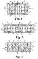
- the batteries 2 each having pressure relieving vents 13 within the containers 1 may be arranged in several different layouts, depending on the number and dimensions of the batteries. Three typical layouts are shown in Figures 1 to 3, other layouts being possible. Those shown in Figures 1 and 2 are for single or double pole batteries (double pole batteries being illustrated) whilst that shown in Figure 3 is for single pole batteries. Connectors 14 are provided to suit the particular layout. The sizes of the crates and the lids therefore depend on the layouts and so too do the positions of the cables 15 connecting the batteries to the motor of the vehicle being driven, the cables 15 passing through a side 5 to the outside of the container through apertures having grommets provided therein.
- All three crates shown in Figures 1 to 3 have internal partitions 8, the height of the partition being approximately level with but no higher than the tops of the batteries contained within the container.
- the crates 3 are lined with insulating sheet material 16, and similar sheet material 17 is located between the individual batteries.
- the batteries In use the batteries emit hydrogen gas, which, when mixed with the oxygen in the atmosphere, forms an explosive mixture if the proportion by volume of hydrogen is greater than 4%.
- the containers are ventilated by means of the ventilation openings 9 referred to above and by means of apertures 18 formed in the lid 4.
- the openings are provided between adjacent louvres 19 and between a louvre and the lid 4.
- an opening may be provided between the top edge 25 of the side 5 and the lowest louvre 19.
- the maximum vertical height of an opening is 12 mm. This is in accordance with the requirements of IP 23 IEC 529 (1989-11) and is intended to prevent a person pushing one of their fingers through the opening.
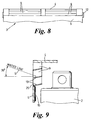
- the louvres are tilted so as to slope from the inside of the container downwards towards the outside, thus preventing most of the water in a spray at an angle of up to 30° from the horizontal (as shown by line S) from entering the container and thus meeting the requirements of the regulations referred to above.
- the openings are constructed and arranged so that the total open area, measured vertically, is at least 1320 mm 2 per kilowatt hour of the capacity of the batteries within the container.
- the openings 9 may be arranged as one array per side as shown in Figures 4 to 7, two arrays per side as shown in Figure 8, or for very large containers, 3 arrays per side.
- the total vertical open distance of the spaces between the louvres etc is 36 mm and the total array length of the openings (around all sides) is such that the total open area is 1320 mm 2 per kilowatt hour.
- the total horizontal length around all four sides is 2523 mm and the vertical distance is 36 mm, so the total open area is 90,828 mm 2 equal to 1320 mm 2 per kilowatt hour.
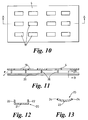
- the apertures 18 in the lids are generally rectangular (but may be of other shapes, eg circular) arranged in rows. Under each row is a channel 20 to catch any water falling through the apertures 18 and to lead it to an opening 9 where it falls out of the container as indicated by the arrow F in Figure 11.
- the channels 20, made of sheet steel, may be of any suitable shape; two examples are shown in Figures 12 and 13.
- the first example shown in Figure 12 comprises a narrow base strip 21 with two upwardly-directed edge portions 22, the edge portions being perpendicular to the strip.
- the channel slopes to ensure that any water collected flows away through a ventilation opening.
- the edge portions may be formed by bending the sides of the strip or welding separate smaller strips to the side of the base strip.
- the second example shown in Figure 13, comprises a strip 23 with a curved cross-section, the edges 24 of the strip extending upwardly. Again the whole strip slopes so as to ensure water flows away.
- Both examples of channels are supported below a row of apertures by means of short rods 26 (see Figure 10) secured to the underside of the lid 4.
- the upper extremities of the edge portions 22 of the first example or of the edges 24 of the second example are a maximum of 12 mm below the underside of the lid 4.
- the channels 20 have a width of 70 mm, ie greater than the width of the aperture which may for example have a width of 25 mm, in order to meet the requirements of IP23 IEC 529 (1989-11).
- the total area of the apertures is 58,480 mm 2 ie equal to 858 mm 2 per kilowatt hour, which is greater than the minimum value of 850 mm 2 per kilowatt hour referred to above
- the overall height of the openings is substantially less than hitherto.
- the height for a container for 40 batteries is 58 mm less than a container having no ventilation apertures in the lid.
- the container of the invention can therefore be fitted to conventional fork lift trucks (or similar vehicles) with little or no need for adaptation or modification.
Landscapes
- Chemical & Material Sciences (AREA)
- Chemical Kinetics & Catalysis (AREA)
- Electrochemistry (AREA)
- General Chemical & Material Sciences (AREA)
- Battery Mounting, Suspending (AREA)
- Sealing Battery Cases Or Jackets (AREA)
Abstract
Description
- This invention relates to a battery container.
- When used in certain circumstances, for example as the power source for a vehicle, lead acid batteries are located in containers to provide protection against objects such as tools being dropped on to the terminals or connectors (thereby causing an electrical short or a spark) or against material such as water in the form of a spray or jet. The battery container according to the present invention is intended to meet the requirements of the degree of protection regulations IP 23 according to IEC Publication No. 529 (1989-11).
- However, when in use, and therefore discharging, lead acid batteries emit hydrogen gas. When this hydrogen is mixed with oxygen present in the air, and the amount exceeds 4% by volume, there is danger of a fire or explosion. In order to eliminate these dangers, especially if the vehicle is used in an environment such as in a mine where other flammable or explosive gases are likely to be present, the containers have to be well ventilated. To allow a safety margin, containers are constructed to ensure that the amount of hydrogen in the air immediately adjacent the batteries is less than 2%, thus meeting the requirements of BSEN 50014 and BSEN 50019.
- Previously known containers, constructed to meet the above-mentioned regulations, have comprised rectangular boxes made of
sheet steel eg 3 mm thick. The tops of these boxes are unbroken, i.e. devoid of any aperture, and vents in the form of elongated rectangular openings have been provided at the top of each side immediately below the lid. Sometimes for convenience part of each side has been attached to the lid and the vents located in these parts. - However it has been found that when using the previously known containers the height of the lid above the battery terminals, required to ensure that the vents have sufficiently large cross-sectional area, is a disadvantage since the vehicles to which these containers and batteries are fitted have to be modified. For example a fork-lift truck used in a factory environment where the aforementioned regulations do not apply can be fitted with batteries without the need for containers as described above. If the same truck is used in a mine, or a
Zone 1 area, according to European IEC classification, where explosive or flammable gases or vapours occur and where the regulations do apply, then the batteries must be in containers and the fork-lift trucks have to be modified. Since the driver's seat is usually above the space reserved for the batteries, the modification is extensive and therefore expensive. - It is an object of the present invention to provide a battery container which substantially overcomes the effect of the above disadvantages.
- In accordance with the invention a container for at least one battery comprises a box having a rectangular base, four vertical rectangular sides and a rectangular lid, each side comprising a ventilation opening, the total open area of the openings measured in a vertical plane parallel to the respective side being at least 1320 mm2 per kilowatt hour of the total capacity of the battery within the container, each opening having a maximum width of 12 mm, and the lid comprising a plurality of apertures and at least one drainage channel having upwardly-directed edges beneath the apertures, the vertical distance between each edge and the lid being a maximum of 12 mm, and the total open area, measured vertically between the edges and the lid, being at least 850 mm2 per kilowatt hour of the total capacity of the battery within the container.
- The total area of the ventilation openings in the sides and of the apertures in the lid meets the requirements of BSEN 50014 and BSEN 50019 since it is found that the percentage by volume of hydrogen gas within the space immediately above the battery in the container in accordance with the invention is less than 2% and of the order of 1.6 %.
- The ventilation openings, either in part of the sides attached to the lid or in the sides themselves, meet the degree of protection regulations IP 23 according to IEC publication No. 529 (1989-11). Preferably at least one louvre is provided defining a boundary of an opening, the louvre being tilted so that any water landing on the upper surface thereof flows away to the exterior of the container.
- The lid is preferably formed with a plurality of apertures, eg rectangular in shape, arranged in rows in a rectangular matrix. Supported below each row of apertures, by support means such as rods, is the drainage channel having upwardly directed edges. The channel may be of any suitable cross-sectional form having at least one end positioned either above a louvre or at any other suitable position to ensure that water in the channel flows away to the exterior of the container. Preferably the channel has a small slope from one end to the other and the lower end directs any water to the exterior of the container. The position of the channel in relation to the apertures in the lids meet the requirements of the degree of protection regulations referred to above.
- The invention will now be described by way of example only with reference to and as illustrated in the accompanying drawings of which:-
- Figures 1 to 3 show plan views of three typical battery layouts, each within a crate;
- Figure 4 shows a side view of a container comprising a crate and a lid, ventilation openings between louvres being provided on a side of the lid;
- Figure 5 shows a side view of a crate and a lid, ventilation openings between louvres being on a side of the crate;
- Figure 6 shows a partial side view of the container showing Figure 4 with a hinged lid;
- Figure 7 shows a partial side view of the container shown in Figure 5 with a hinged lid;
- Figure 8 shows a partial view of an alternative arrangement of openings;
- Figure 9 shows an enlarged cross-sectional detail of the openings of a container according to the invention;
- Figure 10 shows a plan view of the lid of a container according to the invention;
- Figure 11 shows a cross-section on line A-A of Figure 10; and
- Figures 12 and 13 show two examples of channels, being cross-sections on line B-B of Figure 11.
-
- In accordance with the invention a
container 1 for a plurality ofvehicle drive batteries 2 comprises a box consisting of acrate 3 and a lid 4. The crate comprises foursides 5 and abase 6, each of sheet steel at least 3 mm thick.Drainage holes 7 are provided in thebase 6.Partitions 8 of sheet steel are also provided and as shown may comprise two sheets. The height of the partitions is lower than the sides, the tops of the partitions being level with or slightly below the top surfaces of the batteries. The lid 4 also comprises sheet steel at least 3 mm thick. -
Ventilation openings 9 are provided, either formed in part of the sides attached to the lid 4 as shown in Figures 4 and 6 or formed in the upper parts of thesides 5 of thecrates 3 as shown in Figures 5, 7 and 8. The lid 4 may either be capable of being lifted off completely or attached by means of ahinge 10 as shown in Figures 6 and 7.Suitable stays 11 may be provided for the hinged lids as shown in Figures 6 and 7 andlockable clasps 12 or the like may be provided for either type of lid. - The
batteries 2 each havingpressure relieving vents 13 within thecontainers 1 may be arranged in several different layouts, depending on the number and dimensions of the batteries. Three typical layouts are shown in Figures 1 to 3, other layouts being possible. Those shown in Figures 1 and 2 are for single or double pole batteries (double pole batteries being illustrated) whilst that shown in Figure 3 is for single pole batteries.Connectors 14 are provided to suit the particular layout. The sizes of the crates and the lids therefore depend on the layouts and so too do the positions of thecables 15 connecting the batteries to the motor of the vehicle being driven, thecables 15 passing through aside 5 to the outside of the container through apertures having grommets provided therein. - All three crates shown in Figures 1 to 3 have
internal partitions 8, the height of the partition being approximately level with but no higher than the tops of the batteries contained within the container. Thecrates 3 are lined withinsulating sheet material 16, andsimilar sheet material 17 is located between the individual batteries. - In use the batteries emit hydrogen gas, which, when mixed with the oxygen in the atmosphere, forms an explosive mixture if the proportion by volume of hydrogen is greater than 4%. In order to prevent an explosion, the containers are ventilated by means of the
ventilation openings 9 referred to above and by means ofapertures 18 formed in the lid 4. - As can be seen particularly in Figure 9, the openings are provided between
adjacent louvres 19 and between a louvre and the lid 4. In an alternative construction (not shown) an opening may be provided between thetop edge 25 of theside 5 and thelowest louvre 19. The maximum vertical height of an opening is 12 mm. This is in accordance with the requirements of IP 23 IEC 529 (1989-11) and is intended to prevent a person pushing one of their fingers through the opening. Further, the louvres are tilted so as to slope from the inside of the container downwards towards the outside, thus preventing most of the water in a spray at an angle of up to 30° from the horizontal (as shown by line S) from entering the container and thus meeting the requirements of the regulations referred to above. - The openings are constructed and arranged so that the total open area, measured vertically, is at least 1320 mm2 per kilowatt hour of the capacity of the batteries within the container. The
openings 9 may be arranged as one array per side as shown in Figures 4 to 7, two arrays per side as shown in Figure 8, or for very large containers, 3 arrays per side. - For example, as shown in Figure 8 the total vertical open distance of the spaces between the louvres etc is 36 mm and the total array length of the openings (around all sides) is such that the total open area is 1320 mm2 per kilowatt hour. For example for a container containing 40 batteries ie 80 volts, with a capacity of 860 ampere hours (68.8 kilowatt hours), the total horizontal length around all four sides is 2523 mm and the vertical distance is 36 mm, so the total open area is 90,828 mm2 equal to 1320 mm2 per kilowatt hour.
- The
apertures 18 in the lids are generally rectangular (but may be of other shapes, eg circular) arranged in rows. Under each row is achannel 20 to catch any water falling through theapertures 18 and to lead it to anopening 9 where it falls out of the container as indicated by the arrow F in Figure 11. Thechannels 20, made of sheet steel, may be of any suitable shape; two examples are shown in Figures 12 and 13. The first example shown in Figure 12 comprises anarrow base strip 21 with two upwardly-directededge portions 22, the edge portions being perpendicular to the strip. The channel slopes to ensure that any water collected flows away through a ventilation opening. The edge portions may be formed by bending the sides of the strip or welding separate smaller strips to the side of the base strip. The second example, shown in Figure 13, comprises astrip 23 with a curved cross-section, theedges 24 of the strip extending upwardly. Again the whole strip slopes so as to ensure water flows away. Both examples of channels are supported below a row of apertures by means of short rods 26 (see Figure 10) secured to the underside of the lid 4. The upper extremities of theedge portions 22 of the first example or of theedges 24 of the second example are a maximum of 12 mm below the underside of the lid 4. Thechannels 20 have a width of 70 mm, ie greater than the width of the aperture which may for example have a width of 25 mm, in order to meet the requirements of IP23 IEC 529 (1989-11). - In one example the lid has twelve
apertures 18 each having a size of 195 mm x 25 mm to ensure that the total open area, measured vertically, that is total area = 12 mm (vertical spacing) x 205 mm (length) x 2 (2 sides to the aperture) x 12 (the number of apertures) is greater than 850 mm2 per kilowatt hour of battery capacity. Thus for a container containing 40 batteries ie 80 volts, with a capacity of 860 ampere hour (68.8 kilowatt hour), the total area of the apertures is 58,480 mm2 ie equal to 858 mm2 per kilowatt hour, which is greater than the minimum value of 850 mm2 per kilowatt hour referred to above - In use when the batteries are discharging hydrogen gas is emitted and, being less dense than air, rises through the apertures and the upper parts of the openings taking some air with it. Air from outside the container thus flows into the lower parts of the openings.
- Because of the provision of
apertures 18 in the lid 4, the overall height of the openings is substantially less than hitherto. For example the height for a container for 40 batteries is 58 mm less than a container having no ventilation apertures in the lid. The container of the invention can therefore be fitted to conventional fork lift trucks (or similar vehicles) with little or no need for adaptation or modification.
Claims (10)
- A container (1) for at least one battery comprising a (3) box having a rectangular base (6), four vertical rectangular sides (5) and a rectangular lid (4), each side (5) comprising a ventilation opening (9), the total open area of the openings (9) measured in a vertical plane parallel to the respective side being at least 1320 mm2 per kilowatt hour of the total capacity of the battery within the container, each opening (9) having a maximum width of 12 mm, and the lid (4) comprising a plurality of apertures (18) and at least one drainage channel (20) having upwardly directed edges (22 or 24) beneath the apertures, the vertical distance between each edge (22 or 24) and the lid (4) being a maximum of 12 mm, and the total open area, measured vertically between the edges (22 or 24) and the lid (4) , being at least 850 mm2 per kilowatt hour of the total capacity of the battery within the container.
- A container (1) according to Claim 1 characterised in that the ventilation openings (9) are in part of the sides (5) attached to the lid (4).
- A container (1) according to Claim 1 characterised in that the ventilation openings (9) are in the sides (5).
- A container (1) according to any one of the preceding claims characterised by comprising at least one louvre (19) defining a boundary of an opening (9), the louvre (19) being tilted so that any water landing on the upper surface thereof flows away to the exterior of the container (1).
- A container (1) according to any one of the preceding claims characterised in that the lid (4) is formed with a plurality of apertures (18) arranged in rows.
- A container (1) according to Claim 5 characterised in that the apertures (18) are arranged in rows in a rectangular matrix.
- A container (1) according to Claim 5 or Claim 6 characterised in that a drainage channel (20) is supported below each row by support means.
- A container (1) according to Claim 7 characterised in that the support means comprises a plurality of rods (26).
- A container (1) according to any one of the preceding claims characterised in that the channel (20) has at least one end positioned to ensure that water in the channel (20) flows away to the exterior of the container (1).
- A container (1) according to Claim 9 characterised in that the channel (20) has a small slope from one end to the other and the lower end directs any water to the exterior of the container (1).
Applications Claiming Priority (2)
| Application Number | Priority Date | Filing Date | Title |
|---|---|---|---|
| GB9807022 | 1998-04-02 | ||
| GBGB9807022.0A GB9807022D0 (en) | 1998-04-02 | 1998-04-02 | Battery container |
Publications (2)
| Publication Number | Publication Date |
|---|---|
| EP0949697A1 true EP0949697A1 (en) | 1999-10-13 |
| EP0949697B1 EP0949697B1 (en) | 2004-02-04 |
Family
ID=10829697
Family Applications (1)
| Application Number | Title | Priority Date | Filing Date |
|---|---|---|---|
| EP99106033A Expired - Lifetime EP0949697B1 (en) | 1998-04-02 | 1999-03-25 | Battery container |
Country Status (4)
| Country | Link |
|---|---|
| US (1) | US6197447B1 (en) |
| EP (1) | EP0949697B1 (en) |
| DE (1) | DE69914519T2 (en) |
| GB (2) | GB9807022D0 (en) |
Families Citing this family (4)
| Publication number | Priority date | Publication date | Assignee | Title |
|---|---|---|---|---|
| US8895171B2 (en) * | 2007-10-23 | 2014-11-25 | Ford Global Technologies, Llc | System for cooling a vehicle battery and method of installing same |
| US20110052967A1 (en) * | 2009-08-27 | 2011-03-03 | International Truck Intellectual Property Company, Llc. | Cableless battery connection system |
| US9831482B2 (en) | 2013-09-06 | 2017-11-28 | Johnson Controls Technology Company | Battery module lid system and method |
| JP6248487B2 (en) * | 2013-09-12 | 2017-12-20 | 株式会社ジェイテクト | Electric pump device |
Citations (1)
| Publication number | Priority date | Publication date | Assignee | Title |
|---|---|---|---|---|
| GB2081495A (en) * | 1980-07-07 | 1982-02-17 | Fiat Ricerche | Electrical energy storage and supply unit for electric vehicles |
Family Cites Families (3)
| Publication number | Priority date | Publication date | Assignee | Title |
|---|---|---|---|---|
| US4108266A (en) | 1977-04-28 | 1978-08-22 | Towmotor Corporation | Battery enclosure for a lift truck |
| GB2061599B (en) | 1979-10-26 | 1983-10-19 | Hill Rotherham Ltd Thomas | Battery housing |
| GB2077027B (en) | 1980-05-22 | 1983-03-23 | Manufacturing Electrical Desig | Ventilated battery |
-
1998
- 1998-04-02 GB GBGB9807022.0A patent/GB9807022D0/en not_active Ceased
-
1999
- 1999-03-24 US US09/275,299 patent/US6197447B1/en not_active Expired - Lifetime
- 1999-03-25 DE DE69914519T patent/DE69914519T2/en not_active Expired - Lifetime
- 1999-03-25 EP EP99106033A patent/EP0949697B1/en not_active Expired - Lifetime
- 1999-03-25 GB GB9906771A patent/GB2336028B/en not_active Expired - Lifetime
Patent Citations (1)
| Publication number | Priority date | Publication date | Assignee | Title |
|---|---|---|---|---|
| GB2081495A (en) * | 1980-07-07 | 1982-02-17 | Fiat Ricerche | Electrical energy storage and supply unit for electric vehicles |
Also Published As
| Publication number | Publication date |
|---|---|
| US6197447B1 (en) | 2001-03-06 |
| EP0949697B1 (en) | 2004-02-04 |
| DE69914519D1 (en) | 2004-03-11 |
| GB2336028B (en) | 2000-07-12 |
| GB2336028A (en) | 1999-10-06 |
| DE69914519T2 (en) | 2004-12-30 |
| GB9807022D0 (en) | 1998-06-03 |
| GB9906771D0 (en) | 1999-05-19 |
Similar Documents
| Publication | Publication Date | Title |
|---|---|---|
| US11165116B2 (en) | Battery for an industrial truck | |
| US6406812B1 (en) | Continuous current supply for electrical automotive vehicle | |
| CN112203942B (en) | Repairable plastic pallet with movable support block and related method | |
| US7323272B2 (en) | Battery enclosure for electric and hybrid electric vehicles optimized for air-cooling | |
| US8530069B2 (en) | Battery module | |
| EP2092584B1 (en) | Battery module | |
| CA1221730A (en) | Storage battery construction | |
| DE69427248T2 (en) | Tray arrangement of gas-tight lead acid cells and motor vehicle using such a tray arrangement of cells | |
| JP2022545135A (en) | battery pack and vehicle | |
| DE60109130T2 (en) | Electric accumulator battery | |
| WO2000057502A1 (en) | A venting system for a battery | |
| EP0949697B1 (en) | Battery container | |
| US5278003A (en) | Cover assembly for maintenance-free lead-acid batteries | |
| DE102023109516A1 (en) | BATTERY HOUSING ASSEMBLY FOR ELECTRIC VEHICLES | |
| CA1129949A (en) | Vent cover for maintenance-free battery | |
| US3966074A (en) | Terminal box and cover | |
| GB1599354A (en) | Explosion resistant battery cover design | |
| NO306085B1 (en) | Accumulator, especially lead accumulator, preferably for utility vehicles | |
| KR102425700B1 (en) | Tray for packing secondary battery | |
| EP0107469B1 (en) | Low silhouette venting system for electric storage battery | |
| US7368201B1 (en) | Box for set of electric storage batteries | |
| US3457119A (en) | Storage battery with detachable cover having lifting means | |
| JP2025119461A (en) | Electricity storage device and vehicle | |
| CN110040480B (en) | Discharging machine and discharging method thereof | |
| EP4668454A1 (en) | Battery pack and vehicle including same |
Legal Events
| Date | Code | Title | Description |
|---|---|---|---|
| PUAI | Public reference made under article 153(3) epc to a published international application that has entered the european phase |
Free format text: ORIGINAL CODE: 0009012 |
|
| AK | Designated contracting states |
Kind code of ref document: A1 Designated state(s): AT BE CH CY DE DK ES FI FR GB GR IE IT LI LU MC NL PT SE |
|
| AX | Request for extension of the european patent |
Free format text: AL;LT;LV;MK;RO;SI |
|
| 17P | Request for examination filed |
Effective date: 20000413 |
|
| AKX | Designation fees paid |
Free format text: AT BE CH CY DE DK ES FI FR GB GR IE IT LI LU MC NL PT SE |
|
| AXX | Extension fees paid |
Free format text: AL;LT;LV;MK;RO;SI |
|
| 17Q | First examination report despatched |
Effective date: 20021108 |
|
| GRAP | Despatch of communication of intention to grant a patent |
Free format text: ORIGINAL CODE: EPIDOSNIGR1 |
|
| GRAS | Grant fee paid |
Free format text: ORIGINAL CODE: EPIDOSNIGR3 |
|
| GRAA | (expected) grant |
Free format text: ORIGINAL CODE: 0009210 |
|
| RIN1 | Information on inventor provided before grant (corrected) |
Inventor name: DOWNING, MARK Inventor name: PURDY, GEOFFREY WILLIAM |
|
| AK | Designated contracting states |
Kind code of ref document: B1 Designated state(s): DE FR GB IT NL SE |
|
| REG | Reference to a national code |
Ref country code: GB Ref legal event code: FG4D |
|
| REG | Reference to a national code |
Ref country code: IE Ref legal event code: FG4D |
|
| REF | Corresponds to: |
Ref document number: 69914519 Country of ref document: DE Date of ref document: 20040311 Kind code of ref document: P |
|
| REG | Reference to a national code |
Ref country code: SE Ref legal event code: TRGR |
|
| RAP2 | Party data changed (patent owner data changed or rights of a patent transferred) |
Owner name: HAWKER S.A. |
|
| NLT2 | Nl: modifications (of names), taken from the european patent patent bulletin |
Owner name: HAWKER S.A. |
|
| ET | Fr: translation filed | ||
| PLBE | No opposition filed within time limit |
Free format text: ORIGINAL CODE: 0009261 |
|
| STAA | Information on the status of an ep patent application or granted ep patent |
Free format text: STATUS: NO OPPOSITION FILED WITHIN TIME LIMIT |
|
| 26N | No opposition filed |
Effective date: 20041105 |
|
| PGFP | Annual fee paid to national office [announced via postgrant information from national office to epo] |
Ref country code: SE Payment date: 20110331 Year of fee payment: 13 |
|
| PGFP | Annual fee paid to national office [announced via postgrant information from national office to epo] |
Ref country code: GB Payment date: 20110426 Year of fee payment: 13 |
|
| REG | Reference to a national code |
Ref country code: SE Ref legal event code: EUG |
|
| PG25 | Lapsed in a contracting state [announced via postgrant information from national office to epo] |
Ref country code: SE Free format text: LAPSE BECAUSE OF NON-PAYMENT OF DUE FEES Effective date: 20120326 |
|
| GBPC | Gb: european patent ceased through non-payment of renewal fee |
Effective date: 20120325 |
|
| PG25 | Lapsed in a contracting state [announced via postgrant information from national office to epo] |
Ref country code: GB Free format text: LAPSE BECAUSE OF NON-PAYMENT OF DUE FEES Effective date: 20120325 |
|
| REG | Reference to a national code |
Ref country code: FR Ref legal event code: PLFP Year of fee payment: 18 |
|
| REG | Reference to a national code |
Ref country code: FR Ref legal event code: PLFP Year of fee payment: 19 |
|
| REG | Reference to a national code |
Ref country code: FR Ref legal event code: PLFP Year of fee payment: 20 |
|
| PGFP | Annual fee paid to national office [announced via postgrant information from national office to epo] |
Ref country code: NL Payment date: 20180314 Year of fee payment: 20 Ref country code: DE Payment date: 20180313 Year of fee payment: 20 |
|
| PGFP | Annual fee paid to national office [announced via postgrant information from national office to epo] |
Ref country code: FR Payment date: 20180222 Year of fee payment: 20 Ref country code: IT Payment date: 20180321 Year of fee payment: 20 |
|
| REG | Reference to a national code |
Ref country code: DE Ref legal event code: R071 Ref document number: 69914519 Country of ref document: DE |
|
| REG | Reference to a national code |
Ref country code: NL Ref legal event code: MK Effective date: 20190324 |