EP0949449B1 - Lampe de véhicule avec des lentilles asphériques et des écrans d'occultation pour lesdites lentilles - Google Patents
Lampe de véhicule avec des lentilles asphériques et des écrans d'occultation pour lesdites lentilles Download PDFInfo
- Publication number
- EP0949449B1 EP0949449B1 EP99106871A EP99106871A EP0949449B1 EP 0949449 B1 EP0949449 B1 EP 0949449B1 EP 99106871 A EP99106871 A EP 99106871A EP 99106871 A EP99106871 A EP 99106871A EP 0949449 B1 EP0949449 B1 EP 0949449B1
- Authority
- EP
- European Patent Office
- Prior art keywords
- focal point
- lens
- aspheric
- lamp
- center axis
- Prior art date
- Legal status (The legal status is an assumption and is not a legal conclusion. Google has not performed a legal analysis and makes no representation as to the accuracy of the status listed.)
- Expired - Lifetime
Links
Images


Classifications
-
- B—PERFORMING OPERATIONS; TRANSPORTING
- B60—VEHICLES IN GENERAL
- B60Q—ARRANGEMENT OF SIGNALLING OR LIGHTING DEVICES, THE MOUNTING OR SUPPORTING THEREOF OR CIRCUITS THEREFOR, FOR VEHICLES IN GENERAL
- B60Q1/00—Arrangement of optical signalling or lighting devices, the mounting or supporting thereof or circuits therefor
-
- F—MECHANICAL ENGINEERING; LIGHTING; HEATING; WEAPONS; BLASTING
- F21—LIGHTING
- F21S—NON-PORTABLE LIGHTING DEVICES; SYSTEMS THEREOF; VEHICLE LIGHTING DEVICES SPECIALLY ADAPTED FOR VEHICLE EXTERIORS
- F21S41/00—Illuminating devices specially adapted for vehicle exteriors, e.g. headlamps
- F21S41/40—Illuminating devices specially adapted for vehicle exteriors, e.g. headlamps characterised by screens, non-reflecting members, light-shielding members or fixed shades
- F21S41/43—Illuminating devices specially adapted for vehicle exteriors, e.g. headlamps characterised by screens, non-reflecting members, light-shielding members or fixed shades characterised by the shape thereof
-
- F—MECHANICAL ENGINEERING; LIGHTING; HEATING; WEAPONS; BLASTING
- F21—LIGHTING
- F21S—NON-PORTABLE LIGHTING DEVICES; SYSTEMS THEREOF; VEHICLE LIGHTING DEVICES SPECIALLY ADAPTED FOR VEHICLE EXTERIORS
- F21S41/00—Illuminating devices specially adapted for vehicle exteriors, e.g. headlamps
- F21S41/20—Illuminating devices specially adapted for vehicle exteriors, e.g. headlamps characterised by refractors, transparent cover plates, light guides or filters
- F21S41/25—Projection lenses
- F21S41/265—Composite lenses; Lenses with a patch-like shape
-
- F—MECHANICAL ENGINEERING; LIGHTING; HEATING; WEAPONS; BLASTING
- F21—LIGHTING
- F21S—NON-PORTABLE LIGHTING DEVICES; SYSTEMS THEREOF; VEHICLE LIGHTING DEVICES SPECIALLY ADAPTED FOR VEHICLE EXTERIORS
- F21S41/00—Illuminating devices specially adapted for vehicle exteriors, e.g. headlamps
- F21S41/20—Illuminating devices specially adapted for vehicle exteriors, e.g. headlamps characterised by refractors, transparent cover plates, light guides or filters
- F21S41/25—Projection lenses
- F21S41/275—Lens surfaces, e.g. coatings or surface structures
-
- F—MECHANICAL ENGINEERING; LIGHTING; HEATING; WEAPONS; BLASTING
- F21—LIGHTING
- F21S—NON-PORTABLE LIGHTING DEVICES; SYSTEMS THEREOF; VEHICLE LIGHTING DEVICES SPECIALLY ADAPTED FOR VEHICLE EXTERIORS
- F21S41/00—Illuminating devices specially adapted for vehicle exteriors, e.g. headlamps
- F21S41/30—Illuminating devices specially adapted for vehicle exteriors, e.g. headlamps characterised by reflectors
- F21S41/32—Optical layout thereof
- F21S41/33—Multi-surface reflectors, e.g. reflectors with facets or reflectors with portions of different curvature
- F21S41/337—Multi-surface reflectors, e.g. reflectors with facets or reflectors with portions of different curvature the reflector having a structured surface, e.g. with facets or corrugations
-
- F—MECHANICAL ENGINEERING; LIGHTING; HEATING; WEAPONS; BLASTING
- F21—LIGHTING
- F21V—FUNCTIONAL FEATURES OR DETAILS OF LIGHTING DEVICES OR SYSTEMS THEREOF; STRUCTURAL COMBINATIONS OF LIGHTING DEVICES WITH OTHER ARTICLES, NOT OTHERWISE PROVIDED FOR
- F21V13/00—Producing particular characteristics or distribution of the light emitted by means of a combination of elements specified in two or more of main groups F21V1/00 - F21V11/00
- F21V13/12—Combinations of only three kinds of elements
-
- F—MECHANICAL ENGINEERING; LIGHTING; HEATING; WEAPONS; BLASTING
- F21—LIGHTING
- F21V—FUNCTIONAL FEATURES OR DETAILS OF LIGHTING DEVICES OR SYSTEMS THEREOF; STRUCTURAL COMBINATIONS OF LIGHTING DEVICES WITH OTHER ARTICLES, NOT OTHERWISE PROVIDED FOR
- F21V5/00—Refractors for light sources
- F21V5/04—Refractors for light sources of lens shape
- F21V5/045—Refractors for light sources of lens shape the lens having discontinuous faces, e.g. Fresnel lenses
-
- F—MECHANICAL ENGINEERING; LIGHTING; HEATING; WEAPONS; BLASTING
- F21—LIGHTING
- F21S—NON-PORTABLE LIGHTING DEVICES; SYSTEMS THEREOF; VEHICLE LIGHTING DEVICES SPECIALLY ADAPTED FOR VEHICLE EXTERIORS
- F21S43/00—Signalling devices specially adapted for vehicle exteriors, e.g. brake lamps, direction indicator lights or reversing lights
- F21S43/40—Signalling devices specially adapted for vehicle exteriors, e.g. brake lamps, direction indicator lights or reversing lights characterised by the combination of reflectors and refractors
-
- F—MECHANICAL ENGINEERING; LIGHTING; HEATING; WEAPONS; BLASTING
- F21—LIGHTING
- F21V—FUNCTIONAL FEATURES OR DETAILS OF LIGHTING DEVICES OR SYSTEMS THEREOF; STRUCTURAL COMBINATIONS OF LIGHTING DEVICES WITH OTHER ARTICLES, NOT OTHERWISE PROVIDED FOR
- F21V11/00—Screens not covered by groups F21V1/00, F21V3/00, F21V7/00 or F21V9/00
- F21V11/08—Screens not covered by groups F21V1/00, F21V3/00, F21V7/00 or F21V9/00 using diaphragms containing one or more apertures
- F21V11/14—Screens not covered by groups F21V1/00, F21V3/00, F21V7/00 or F21V9/00 using diaphragms containing one or more apertures with many small apertures
-
- F—MECHANICAL ENGINEERING; LIGHTING; HEATING; WEAPONS; BLASTING
- F21—LIGHTING
- F21W—INDEXING SCHEME ASSOCIATED WITH SUBCLASSES F21K, F21L, F21S and F21V, RELATING TO USES OR APPLICATIONS OF LIGHTING DEVICES OR SYSTEMS
- F21W2111/00—Use or application of lighting devices or systems for signalling, marking or indicating, not provided for in codes F21W2102/00 – F21W2107/00
Definitions
- the present invention relates to a lamp and, more particularly, to a lamp suitable for use as an illumination lamp for a vehicle such as a head lamp or fog lamp, a signal lamp for a vehicle such as a tail lamp or turn signal lamp, a signal lamp for road traffic, or a signal lamp for railway traffic.
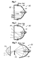
- FIGS. 1 to 3 show conventional lamps of this type.
- a lamp 90 shown in FIG. 1 basically includes: a light source 91; a revolutional paraboloidal reflector 92 having the light source 91 disposed at a focal point thereof; and a lens 93 with a lens cut 93a.
- a light beam from the light source 91 is reflected by the revolutional paraboloidal reflector 92 to form a parallel light beam.
- the reflected light beam is diffused properly by the lens cut 93a of the lens 93 to provide a desired light distribution property.
- a lamp 80 shown in FIG. 2 includes a light source 81; a reflector composed of a composite reflecting surface 82; and a lens 83.
- the composite reflecting surface 82 has a plurality of cylindrical parabolic reflecting surfaces that are arranged to have a parabolic configuration in a vertical cross section taken when the lamp 80 is in a mounted state and have a linear configuration in a horizontal cross section (the state shown in the drawing).
- the lens 83 has no lens cut so that it is see-through.
- the composite reflecting surface 82 provides the light distribution property by itself.
- a lamp 70 shown in FIG. 3 includes: a light source 71; a reflector composed of an elliptic reflecting surface 72 having the light source 71 disposed at a first focal point thereof; an aspheric lens 73; and a shade 74 provided if necessary.
- the elliptic reflecting surface is composed of a spheroid, a composite elliptic surface, or an elliptic free-form surface.
- the aspheric lens 73 projects, under magnification, a light source image formed by converging a light beam at a second focal point to provide an irradiating light beam.
- the lamp 70 of the type using the elliptic reflecting surface 72 is termed a projector type lamp.
- the light distribution property is obtained by covering an unwanted portion with the shade 74.
- the lens cut 93a should be formed to have high optical intensity, so that a significant variation is produced in the thickness of the lens 93. This degrades the transparency of the lens and makes it impossible to provide an appearance with enhanced clarity and sense of depth, which is currently preferred on the market.
- the lamp 70 shown in FIG. 3 is difficult to mount because of its increased depth dimension. Moreover, the aspheric lens 73 having a small outer diameter leads to a reduced light-emitting area. Therefore, the lamp 70 used as a headlight is inferior in visibility when viewed from an oncoming vehicle.
- Each of the conventional lamps 70, 80, and 90 with the aforesaid structures is generally in wide use. Hence, it is impossible to distinguish them from other items and achieve novelty in terms of design. Furthermore, since the coefficient of use of a luminous flux from the light source is dependent on the depth dimension, the coefficient of use is lowered if the lamp is reduced in thickness.
- US-A-3,558,869 discloses a lamp comprising a light source and a petaline reflector composed of a plurality of reflecting surface units combined radially around a center axis of said light source, each of said reflecting surface units being obtained by cutting, radially around said center axis, a portion from a spheroid having a first focal point located on said center axis and adjacent said light source.
- the petaline reflector further more has a second focal point located on a line passing through said first focal point and tilted appropriately from said center axis such that the cut portion spans a range of 15° to 60° arount the center axis.
- the lamp further comprises aspheric lenses corresponding to said respective second focal points of the reflecting surface units of said petaline reflector and are converging reflected light beams from the respective reflecting surface units.
- Another object of the present invention is to provide a lamp having a light distribution property fee from constraints and exhibiting enhanced flexibility for a light distribution property, particularly in the horizontal direction.
- Still another object of the present invention is to provide a lamp having a desired light-emitting area and improved visibility when viewed from an oncoming vehicle.
- Yet another object of the present invention is to provide a lamp wherein the coefficient of use of a luminous flux from the light source is unaffected by the depth dimension.
- One aspect of the present invention is to provide a lamp comprising: a light source; a petaline reflector composed of a plurality of reflecting surface units combined radially around a center axis of the light source, each of the reflecting surface units being obtained by cutting, radially around the center axis, a portion from a spheroid having a first focal point located on the center axis and adjacent the light source and a second focal point located on a line passing through the first focal point and tilted appropriately from the center axis such that the cut portion spans a range of 15° to 60° around the center axis; and aspheric lenses corresponding to the respective second focal points of the reflecting surface units of the petaline reflector and converging reflected light beams from the respective reflecting surface units.
- the petaline reflector which is a combination thereof, has a reduced depth dimension so that the whole lamp is reduced in thickness and has improved mountability. Moreover, the amount of heat received by each of the aspheric lenses can be reduced by distributing light from the single light source to the plurality of aspheric lenses. As a result, it becomes possible to compose the lenses of a resin and achieve an excellent cost reducing effect.
- shades for forming a light distribution pattern are preferably disposed at respective near-focal points of the aspheric lenses.
- a central reflector obtained by cutting a portion from a spheroid having a first focal point adjacent the light source for causing the center axis to coincide with a long axis thereof and an aspheric lens located to correspond to a second focal point of the central reflector are preferably disposed on the center axis.
- the majority of light from the light source can be used as effective irradiating light. This increases the coefficient of use of a luminous flux from the light source and effectively improves the performance of the lamp, thereby providing a brighter lamp. Since the plurality of aspheric lenses have enlarged the light-emitting area, visibility from the viewpoint of the oncoming vehicle is also improved.
- a shade for forming a light distribution pattern is preferably disposed at a near-focal point of the aspheric lens disposed to correspond to the central reflector.
- Another aspect of the present invention is to provide a lamp comprising: a light source; a petaline reflector composed of a plurality of reflecting surface units combined radially around a center axis of the light source, each of the reflecting surface units being obtained by cutting, radially around the center axis, a portion from an elliptic free-form surface having a first focal point located on the center axis and adjacent the light source and a second focal point which is linear in a direction horizontal to the lamp in a mounted state and located on a line passing through the first focal point and tilted appropriately from the center axis such that the cut portion spans a range of 15° to 60 ° around the center axis; and aspheric lenses corresponding to the respective second focal points of the reflecting surface units of the petaline reflector and converging reflected light beams from the respective reflecting surface units.
- a shade for forming a light distribution pattern is preferably disposed at a near-focal point of the aspheric lens, the shade for forming a light distribution pattern preferably having a configuration corresponding to the position of the second focal point which is linear in the horizontal direction such that the both end portions of the shade are curved horizontally symmetrically relative to the near-focal point of the aspheric lens toward the aspheric lens.
- a central reflector configured as an elliptic free-form surface for causing the center axis to coincide with a long axis, locating a first focal point adjacent the light source, and forming a second focal point which is linear in a direction horizontal to the lamp in a mounted state and an aspheric lens located to correspond to the second focal point of the central reflector are preferably disposed on the center axis.
- a shade for forming a light distribution pattern is preferably disposed at a near-focal point of the aspheric lens disposed to correspond to the central reflector, the shade for forming a light distribution pattern preferably having a configuration corresponding to the second focal point changing in position in the horizontal direction such that the both end portion of the shade are curved horizontally symmetrically relative to the near-focal point of the aspheric lens toward the aspheric lens.
- all the aspheric lenses are formed integrally with a lens holder portion and the lens holder portion is formed transparent or opaque.
- the lens holder portion By providing the lens holder portion and forming all the aspheric lenses integrally therewith, if the lens holder portion is transparent, it becomes possible to mix an image from the lens holder portion through which the inner surface of the lamp is viewed as it is with an image from the aspheric lenses through which the inner surface of the lamp is viewed under magnification, thereby providing a novel appearance.
- each of the aspheric lenses is preferably composed of any one selected from a convex lens, a Fresnel lens, and a combination thereof.
- the aspheric lens is formed in a Fresnel configuration, an appearance like crystal glass can be obtained.
- the present invention offers wider design variations to a lamp and achieves an excellent effect in improving the marketability of the lamp.
- each of the aspheric lenses may have a configuration partly combined with a cylindrical lens.
- At least one of the surfaces of the shade for forming a light distribution pattern viewed through the aspheric lens and the lens holder portion may be in a color other than the color of the aspheric lens.
- the lens holder portion is formed opaque and/or colored and the shade is also colored, it becomes possible to implement a lamp presenting different colors in the ON state and in the OFF state, respectively.
- the light source may be provided with a filter in the form of a cap composed of a diffusion filter or a color filter.
- a reference numeral 1 denotes a lamp according to the first embodiment of the present invention.
- the lamp 1 comprises a light source 2; a petaline reflector 3; and aspheric lenses 4.
- the petaline reflector 3 is formed of a combination of plural reflecting surface units 3a (six reflecting surface units 3a are provided in the first embodiment) .
- the number of the aspheric lenses 4 is commensurate with the number of the reflecting surface units 3a.
- a central reflector 6 is further provided along with an aspheric lens 4' and a shade 5' for forming a light distribution pattern, each corresponding to the central reflector 6 (see FIGS. 4 and 5).
- the present invention uses a light source having a single light-emitting source 2b in a bulb 2a.
- the light source 2 include an incandescence lamp with a single filament, a halogen lamp, and a metal halide lamp.
- the petaline reflector 3 is a combination of the plural reflecting surface units 3a.
- the reflecting surface units 3a are arranged relative to the center axis X of the bulb 2a (hereinafter referred to as a bulb center axis X) as the center axis of the light source 2.
- the light-emitting source 2b is present on the bulb center axis X and a first focal point F1 is set at the light-emitting source 2b.
- an oblique line Y passing through the first focal point F1 and tilted appropriately from the bulb center axis X is assumed.
- a second focal point is set on the oblique line Y and an appropriate ellipse having focal points at the first and second focal points F1 and F2 is assumed.
- the spheroid RO1 is obtained by rotating the ellipse around the oblique line Y as an axis. As a result, the spheroid RO1 obtained has a long axis coincident with the oblique line Y.
- Each of the reflecting surface units 3a is obtained by cutting, from the spheroid RO1, a portion having a vertex at the point of intersection of the spheroid RO1 and the bulb center axis X and spanning a range of 15 ° to 60 ° around the bulb center axis X such that the cut portion is bilaterally symmetrical with respect to the oblique line Y (long axis).
- the inner side of the spheroid RO1 is used as the reflecting surface.
- the first embodiment has adopted the spheroid RO1 that has been cut at the position at which the reflecting surface appears when viewed from the front side of the lamp 1.
- the plurality of reflecting surface units 3a thus obtained are combined with each other to form the petaline reflector 3.
- four to ten reflecting surface units 3a are preferably combined.
- the aspheric lenses 4 having respective focal lengths of 10 to 60 mm are disposed such that the optical axes Z of the aspheric lenses 4 are nearly parallel to the bulb center axis X.
- the positional relationship between the second focal points F2 and the aspheric lenses 4 may be established in the same manner as established in the conventional projector type lamp shown in FIG. 3.
- the lamp 1 thus structured has a generally circular light distribution property. If the lamp 1 is used as a headlight for a vehicle to emit a low beam, for example, it is required to provide a light distribution property suitable for the low beam.
- the present invention may dispose the shades 5 for forming a light distribution pattern at the respective near-focal points of the aspheric lenses 4.
- the shades 5 for forming a light distribution pattern may be composed of any shades provided that they have the same shielding effect as achieved by the shades of the conventional embodiment shown in FIG. 3.
- the central reflector 6 formed from a spheroid, which is for causing the bulb center axis X to coincide with the long axis, as indicated by the dash-dot lines and curves in FIGS. 4 and 5.
- the first focal point F1 of the central reflector 6 is positioned at the light-emitting source 2b, similarly to each of the reflecting surface units 3a.
- a second focal point F3 is set on the bulb center axis X to obtain a spheroid R02.
- the central reflector 6 is formed by removing an unwanted portion from the spheroid RO2.
- the aspheric lens 4' is disposed by the same means as used in the case of the reflecting surface units 3a. If required, the shade 5' for forming a light distribution pattern may also be disposed by the same means as used in the case of the reflecting surface units 3a.
- the aspheric lens 4' corresponding to the central reflector 6 is present at the center position surrounded by the aspheric lenses 4 corresponding to the respective reflecting surface units 3a arranged radially, as indicated by the dash-dot curve in FIG. 6.
- each of the reflecting surface units 3a is formed under the same conditions, the aspheric lenses 4 corresponding to the respective reflecting surface units 3a are present on the same plane which is equidistant from and orthogonal to the bulb center axis X. If the plane orthogonal to the bulb center axis X is formed as a lens holder portion 4a, therefore, all the aspheric lenses 4 corresponding to the respective reflecting surface units 3a can be formed into one body.
- the aspheric lens 4' corresponding to the central reflector 6 may change its position either forward or backward on the bulb center axis X depending on the form of the central reflector 6.
- the aspheric lens 4' can be positioned on the plane of the lens holder 4a by properly positioning the second focal point F3 of the central reflector 6 or adjusting the focal length of the aspheric lens 4' corresponding to the central reflector 6.
- all the aspheric lenses 4 and 4' can be formed into one body.
- the lens holder portion 4a has no immediate involvement in the formation of the light distribution property or the like.
- the lens holder portion 4a may also be formed of the same material as forming the aspheric lenses 4 and 4'.
- the lens holder portion 4a may be formed in a different color or opaque by a method of two color molding or the like. It is to be noted that the shades 5 and 5' for forming a light distribution pattern may also be formed into one body by a similar method (see FIG. 4).
- the aspheric lenses 4 and 4' are formed integrally with the lens holder portion 4a and the color imparted to the frame of the vehicle is also imparted to the lens holder portion 4a and to the sides of the shades 5 and 5' which are closer to the aspheric lenses 4, the color of the lens holder portion 4a is recognized during the daytime, while the color imparted to the shades 5 and 5' for forming a distribution pattern can be viewed through the aspheric lenses 4 and 4'. This enables the entire lamp 1 to be viewed from every direction in the same color as the car frame and increases design flexibility.
- a reference numeral 7 denotes a filter.
- the filter 7 is in the form of a cap covering the light source 2.
- the filter 7 is formed to have the function of diffusing or coloring a light beam emitted from the light source 2 and reaching the petaline reflector 3 and the central reflector 6.
- a contrast difference between an illuminated place and an unilluminated place tends to be significant.
- a filter having a frosted surface or the like and proper diffusiveness is used as the filter 7, the light beam from the light source 2 is properly diffused on passing through the filter 7, so that the significant contrast difference is alleviated.
- the lamp 1 is also possible to use the lamp 1 as a fog lamp or a traffic signal lamp in the color of red, blue, yellow, or the like by imparting an appropriate color such as amber to the filter 7 instead of imparting diffusiveness thereto.
- FIG. 7 shows a principal portion of the second embodiment of the present invention.
- the reflecting surface unit 3a composing the petaline reflector 3 is configured as a spheroid.
- an illuminating light beam provided in the horizontal direction by the spheroidal reflecting surface has only an insufficient width.
- the second embodiment has been implemented in view of the foregoing and the reflecting surface unit 13a is configured as an elliptic free-form surface (composite elliptic surface) such that a second focal point F4 linearly expands in the horizontal direction. Since means for forming the reflecting surface from the elliptical free-form surface has widely been used in the conventional projector type lamp (see FIG. 3), the detailed description thereof is omitted here.
- a plurality of reflecting surface units 13a each configured as an elliptic free-form surface having such a second focal point as to linearly expand in the horizontal direction are combined with each other to form a petaline reflecting surface 13.
- a basic light distribution property has a generally elliptic configuration with a long axis extending in the horizontal direction, which compensates for the insufficient width of the illuminating light beam in the horizontal direction.
- a shade 15 for forming a light distribution pattern corresponding to each of the reflecting surface units 13a is disposed between the reflecting surface unit 13a and the aspheric lens 4, similarly to the first embodiment.
- the shade 15 for forming a light distribution pattern has both end portions curved horizontally symmetrically relative to the near focal point of the aspheric lens 4 toward the aspheric lens 4, thereby corresponding to the second focal point expanding linearly in the horizontal direction, which is produced by the reflecting surface units 13a.
- means for curving the shade 15 for forming a light distribution pattern is also used in the conventional projector type lamp (see FIG. 3).
- a central reflector for causing the bulb center axis X to coincide with the long axis (not shown concretely, refer to FIGS. 3 and 4) is provided if an improved coefficient of light use is intended, similarly to the first embodiment.
- the central reflector is configured as an elliptic free-form surface whereby a first focal point F1 is positioned at the light-emitting source 2b and a second focal point, which is linear in the horizontal direction, is positioned on the bulb center axis X, similarly to each of the foregoing reflecting surface units 13a.
- the aspheric lens 4' is disposed to correspond to the second focal point of the central reflector by the same means as used in the case of the reflecting surface units 13a. If necessary, the curved shade for forming a light distribution pattern is disposed by the same method used in the case of the reflecting surface units 13a. Since the second embodiment is similar to the first embodiment in terms of the aspheric lens 4, it is also possible to provide a lens holder portion 4a in the lamp according to the second embodiment and form all the aspheric lenses 4 and 4' into one body.
- FIGS. 8 and 9 show respective principal portions of the third and fourth embodiments of the present invention.
- the aspheric lenses 4 and 4' have been formed as convex lenses in either of the first and second embodiments described above, the present invention is not limited thereto. It is also possible to form an aspheric lens in a Fresnel configuration to provide an aspheric Fresnel lens 14, as shown in FIG. 8 illustrating the third embodiment. Alternatively, it is also possible to form a deformed aspheric lens 24 (24'), which is composed of a center portion 24a in the form of a convex lens and a peripheral portion 24b in the form of a Fresnel lens, as shown in FIG. 9 illustrating the fourth embodiment.
- the aspheric lens 4 has a configuration projecting conspicuously toward the viewer side.
- the forward projection becomes less conspicuous, resulting in a design variation.
- an appearance like crystal glass can be imparted to the lens.
- the thickness of the lens becomes uniform. In the case of forming the aspheric lens portion from a resin, therefore, such deformation as sink does not occur during molding, so that optical accuracy is increased.
- FIG. 10 shows a principal portion of the fifth embodiment of the present invention.
- An aspheric lens 34 (34') in the fifth embodiment is composed of lens portions 34a and 34b and a cylindrical portion 34c.
- the lens portions 34a and 34b are configured as the halves of the aspheric lens 4 illustrated in the first embodiment, which are obtained by halving the aspheric lens 4 with the center axis.
- the lens portions 34a and 34b have their respective divided surfaces connected to the both ends of the cylindrical portion 34c.
Claims (12)
- Lampe (1) comprenant :une source lumineuse (2) ;un réflecteur (3) en forme de pétale composé d'une pluralité d'éléments de surface réfléchissants (3a) combinés radialement autour d'un axe central (X) de ladite source lumineuse, chacun desdits éléments de surface réfléchissants étant obtenu en découpant, radialement autour dudit axe central, une partie provenant d'une surface sphéroïdale ou elliptique de forme quelconque ayant un premier point foyer (F1) situé sur ledit axe central et adjacent à ladite source lumineuse et un second foyer (F2) situé sur une ligne passant par ledit premier foyer et qui est inclinée de façon appropriée par rapport audit axe central de façon que la partie découpée s'étende sur 15° à 60° autour de l'axe central ; etdes lentilles asphériques (4,4') correspondant auxdits seconds foyers respectifs des éléments de surface réfléchissants dudit réflecteur en forme de pétale faisant converger des faisceaux lumineux réfléchis par les éléments de surface réfléchissants respectifs, caractérisée en ce que des écrans (5) destinés à former une forme de distribution lumineuse sont disposés en des points situés sensiblement aux foyers respectifs des lentilles asphériques.
- Lampe selon la revendication 1, dans laquelle un réflecteur central (6) obtenu en découpant une partie d'un sphéroïde ayant un premier foyer (F1) adjacent à ladite source lumineuse de façon à faire coïncider l'axe central avec un axe principal et une lentille sphérique (4'), située de façon à correspondre à un second foyer (F3) du réflecteur central, sont disposés sur ledit axe central.
- Lampe selon la revendication 2, dans laquelle un écran (5') destiné à constituer une forme de distribution lumineuse est disposé en un point situé sensiblement au foyer de la lentille asphérique (4'), de façon à correspondre audit réflecteur central (6).
- Lampe selon la revendication 1, caractérisée en ce que ledit réflecteur central (6) est en forme de surface elliptique quelconque, son second foyer (F2) étant sur une droite de direction horizontale passant par la lampe, celle-ci une fois en place.
- Lampe selon la revendication 4, dans laquelle ledit écran (5) destiné à former une forme de distribution lumineuse est disposé en un point proche du foyer de ladite lentille asphérique (4), cet écran formant une forme de distribution lumineuse ayant une configuration correspondant à la position du second foyer (F2) qui est linéaire dans la direction horizontale, de façon que les deux parties extrêmes de l'écran soient incurvées horizontalement de façon symétrique par rapport au point sensiblement au foyer de la lentille asphérique en direction de celle-ci.
- Lampe selon la revendication 4, dans laquelle ledit réflecteur central (6) en forme de surface elliptique quelconque dont l'axe principal coïncide avec l'axe central sur lequel se situe un premier foyer (F1) adjacent à ladite source lumineuse, forme un second foyer (F3) qui est aligné avec la direction horizontale de la lampe, celle-ci une fois en place et une lentille asphérique (4') disposée pour correspondre au second foyer du réflecteur central sont disposées sur ledit axe central.
- Lampe selon la revendication 6, dans laquelle ledit écran (5') destiné à former une forme de distribution lumineuse est disposé en un point voisin du foyer de la lentille asphérique (4') de façon à correspondre audit réflecteur central (6), ledit écran destiné à former une forme de distribution lumineuse présentant une configuration correspondant au second foyer (F3) changeant de position dans la direction horizontale de façon que les deux parties extrêmes de l'écran soient incurvées horizontalement de façon symétrique par rapport au point voisin du foyer de la lentille asphérique en direction de celle-ci.
- Lampe selon l'une quelconque des revendications 1 à 7, dans laquelle toutes les lentilles asphériques (4, 4') sont faites en une seule pièce incluant une partie porte-lentille, et cette dernière est transparente ou opaque.
- Lampe selon l'une quelconque des revendications 1 à 8, dans laquelle chacune desdites lentilles asphériques (4, 4') est soit une lentille convexe, soit une lentille de Fresnel, soit une combinaison de ces dernières.
- Lampe selon l'une quelconque des revendications 1 à 8, dans laquelle chacune desdites lentilles asphériques (4,4') présente une configuration partiellement combinée avec une lentille cylindrique.
- Lampe selon l'une des revendications 1 ou 8, dans laquelle au moins l'une des surfaces d'écran (5, 5') destinée à former une forme de distribution lumineuse au travers de ladite lentille asphérique (4, 4') ainsi que ladite partie porte-lentille, sont d'une couleur autre que la couleur de la lentille asphérique.
- Lampe selon l'une quelconque des revendications 1 à 11, dans laquelle la source lumineuse (2) est coiffée d'un filtre diffuseur ou d'un filtre coloré.
Applications Claiming Priority (2)
| Application Number | Priority Date | Filing Date | Title |
|---|---|---|---|
| JP9918698 | 1998-04-10 | ||
| JP10099186A JP3005954B2 (ja) | 1998-04-10 | 1998-04-10 | 灯 具 |
Publications (3)
| Publication Number | Publication Date |
|---|---|
| EP0949449A2 EP0949449A2 (fr) | 1999-10-13 |
| EP0949449A3 EP0949449A3 (fr) | 2000-09-06 |
| EP0949449B1 true EP0949449B1 (fr) | 2006-07-05 |
Family
ID=14240627
Family Applications (1)
| Application Number | Title | Priority Date | Filing Date |
|---|---|---|---|
| EP99106871A Expired - Lifetime EP0949449B1 (fr) | 1998-04-10 | 1999-04-07 | Lampe de véhicule avec des lentilles asphériques et des écrans d'occultation pour lesdites lentilles |
Country Status (5)
| Country | Link |
|---|---|
| US (1) | US6109772A (fr) |
| EP (1) | EP0949449B1 (fr) |
| JP (1) | JP3005954B2 (fr) |
| KR (1) | KR19990083118A (fr) |
| DE (1) | DE69932198T2 (fr) |
Families Citing this family (39)
| Publication number | Priority date | Publication date | Assignee | Title |
|---|---|---|---|---|
| JP2945376B1 (ja) * | 1998-05-01 | 1999-09-06 | スタンレー電気株式会社 | 灯 具 |
| DE19851374C2 (de) * | 1998-11-07 | 2001-06-21 | Reitter & Schefenacker Gmbh | Leuchtenoptik für eine Kraftfahrzeugleuchte |
| JP3017195B1 (ja) * | 1998-12-10 | 2000-03-06 | スタンレー電気株式会社 | 灯 具 |
| JP2001155515A (ja) * | 1999-09-14 | 2001-06-08 | Stanley Electric Co Ltd | 多眼プロジェクタランプ |
| JP3904783B2 (ja) * | 1999-11-30 | 2007-04-11 | 株式会社小糸製作所 | 車両用標識灯 |
| JP3542113B2 (ja) | 2000-01-14 | 2004-07-14 | スタンレー電気株式会社 | 多眼式灯具 |
| JP4582733B2 (ja) * | 2000-02-04 | 2010-11-17 | スタンレー電気株式会社 | 車両用灯具 |
| JP3634763B2 (ja) * | 2001-03-23 | 2005-03-30 | スタンレー電気株式会社 | プロジェクタ型ランプ |
| FR2826098B1 (fr) | 2001-06-14 | 2003-12-26 | Valeo Vision | Dispositif d'eclairage ou de signalisation, notamment pour vehicule, comportant plusieurs sources lumineuses |
| JP4094847B2 (ja) | 2001-12-19 | 2008-06-04 | ヤマハ発動機株式会社 | 自動二輪車用ヘッドライト |
| KR20040003569A (ko) * | 2002-07-03 | 2004-01-13 | 현대자동차주식회사 | 자동차용 볼록렌즈 조합형 헤드램프 |
| US20040145910A1 (en) * | 2003-01-29 | 2004-07-29 | Guide Corporation (A Delaware Corporation) | Lighting assembly |
| US7452115B2 (en) | 2003-07-29 | 2008-11-18 | Turhan Alcelik | Headlamp with a continuous long-distance illumination without glaring effects |
| US7040782B2 (en) * | 2004-02-19 | 2006-05-09 | Gelcore, Llc | Off-axis parabolic reflector |
| US20060023457A1 (en) * | 2004-07-08 | 2006-02-02 | Leadford Kevin F | Luminaire utilizing reflecting and refracting optics |
| DE102004040159A1 (de) * | 2004-08-19 | 2006-02-23 | Hella Kgaa Hueck & Co. | Leuchteinheit für Kraftfahrzeuge |
| US20090290336A1 (en) * | 2004-12-13 | 2009-11-26 | Harison Toshiba Lighting Corp. | Lighting device and lighting system |
| JP2006210296A (ja) * | 2005-01-31 | 2006-08-10 | Ichikoh Ind Ltd | 車両用灯具および車両用前照灯装置 |
| JP2006210295A (ja) * | 2005-01-31 | 2006-08-10 | Ichikoh Ind Ltd | 車両用灯具および車両用前照灯装置 |
| JP2006222029A (ja) * | 2005-02-14 | 2006-08-24 | Yamaha Motor Co Ltd | 車両用ライト装置及び該装置を備えた車両 |
| WO2006107287A1 (fr) * | 2005-04-05 | 2006-10-12 | Turhan Alcelik | Phare a eclairage longue distance sans effet d’eblouissement |
| US7357545B2 (en) * | 2005-08-10 | 2008-04-15 | Visteon Global Technologies, Inc. | Multi-focal lens for bi-functional headlamp |
| US7303316B2 (en) * | 2005-08-30 | 2007-12-04 | Mei-Chen Liu | Car lamp structure |
| JP4608645B2 (ja) * | 2005-09-26 | 2011-01-12 | スタンレー電気株式会社 | 車両用灯具 |
| EP2045508A1 (fr) * | 2005-10-07 | 2009-04-08 | Black & Decker, Inc. | Lampe portative |
| US7341365B2 (en) * | 2005-12-16 | 2008-03-11 | Ford Global Technologies, Llc | LED unit for a vehicle lamp assembly |
| US7563008B2 (en) * | 2006-03-28 | 2009-07-21 | Visteon Global Technologies, Inc. | LED projector headlamps using single or multi-faceted lenses |
| US20100208484A1 (en) * | 2006-07-13 | 2010-08-19 | Lawrence Andrew Hoffman | Tribar lighting |
| EP1947382A1 (fr) * | 2007-01-19 | 2008-07-23 | Valeo Vision | Module d'éclairage ou de signalisation d'aspect amélioré |
| US20090103322A1 (en) * | 2007-10-22 | 2009-04-23 | Lawrence Andrew Hoffman | Tri-bar headlight assembly with interchangeable colored dots |
| US7832912B2 (en) * | 2008-04-24 | 2010-11-16 | Ichikoh Industries, Ltd. | Lamp unit for vehicles |
| US7883250B2 (en) * | 2008-04-24 | 2011-02-08 | Ichikoh Industries, Ltd. | Lamp unit for vehicles |
| FR2934031B1 (fr) * | 2008-07-21 | 2020-01-31 | Valeo Vision S.A.S | Module d'eclairage ou de signalisation d'aspect tridimensionnel ameliore |
| JP5394086B2 (ja) * | 2009-01-30 | 2014-01-22 | 株式会社小糸製作所 | 車両用灯具 |
| JP5452241B2 (ja) * | 2010-01-14 | 2014-03-26 | スタンレー電気株式会社 | テールストップランプ |
| US20120230046A1 (en) * | 2011-03-08 | 2012-09-13 | Osram Sylvania Inc. | Vehicular illumination system |
| CN104676409B (zh) * | 2013-11-29 | 2018-10-12 | 海洋王(东莞)照明科技有限公司 | 机车灯及其发光组件 |
| US10076992B2 (en) * | 2015-12-18 | 2018-09-18 | Charles I. Sassoon | LED headlamp with daytime running lamp |
| JP7039787B2 (ja) * | 2017-12-27 | 2022-03-23 | ダイハツ工業株式会社 | 車両用灯具 |
Family Cites Families (7)
| Publication number | Priority date | Publication date | Assignee | Title |
|---|---|---|---|---|
| US1814326A (en) * | 1929-08-02 | 1931-07-14 | Burton E Melton | Headlight |
| US3558869A (en) * | 1967-06-19 | 1971-01-26 | Sylvania Electric Prod | Driving light |
| JPS6129123Y2 (fr) * | 1977-12-29 | 1986-08-28 | ||
| DE3341025A1 (de) * | 1983-11-12 | 1985-05-30 | Robert Bosch Gmbh, 7000 Stuttgart | Nebelscheinwerfer, insbesondere fuer kraftfahrzeuge |
| JP2517368B2 (ja) * | 1988-09-27 | 1996-07-24 | 株式会社小糸製作所 | 自動車用前照灯及び自動車用前照灯装置 |
| FR2710966B1 (fr) * | 1993-10-04 | 1995-12-29 | Valeo Vision | Projecteur à conduit de lumière, notamment pour véhicule automobile. |
| EP0854316B1 (fr) * | 1997-01-17 | 2005-04-27 | Stanley Electric Co., Ltd. | Projecteur |
-
1998
- 1998-04-10 JP JP10099186A patent/JP3005954B2/ja not_active Expired - Fee Related
-
1999
- 1999-04-07 DE DE69932198T patent/DE69932198T2/de not_active Expired - Lifetime
- 1999-04-07 EP EP99106871A patent/EP0949449B1/fr not_active Expired - Lifetime
- 1999-04-09 US US09/289,564 patent/US6109772A/en not_active Expired - Lifetime
- 1999-04-10 KR KR1019990012663A patent/KR19990083118A/ko not_active Application Discontinuation
Also Published As
| Publication number | Publication date |
|---|---|
| JP3005954B2 (ja) | 2000-02-07 |
| EP0949449A3 (fr) | 2000-09-06 |
| JPH11297103A (ja) | 1999-10-29 |
| EP0949449A2 (fr) | 1999-10-13 |
| KR19990083118A (ko) | 1999-11-25 |
| US6109772A (en) | 2000-08-29 |
| DE69932198T2 (de) | 2007-06-06 |
| DE69932198D1 (de) | 2006-08-17 |
Similar Documents
| Publication | Publication Date | Title |
|---|---|---|
| EP0949449B1 (fr) | Lampe de véhicule avec des lentilles asphériques et des écrans d'occultation pour lesdites lentilles | |
| US6152589A (en) | Lamp | |
| US6244731B1 (en) | Lamp comprised of a composite reflector and aspheric lenses | |
| EP0950847B1 (fr) | Lampe, en particulier pour véhicules ou feux de signalisation | |
| CN106969311B (zh) | 车辆用灯具 | |
| KR100438120B1 (ko) | 자동차 헤드 램프 | |
| KR100385605B1 (ko) | 전등 | |
| US6910791B2 (en) | Headlight | |
| EP0371510B1 (fr) | Phare pour véhicules automobiles | |
| JP2003123517A (ja) | 投光ユニットおよび該投光ユニットを具備するled車両用照明灯具 | |
| GB2352801A (en) | Vehicle headlamp | |
| JPH09237504A (ja) | 下向き及び上向きライト用自動車前照灯 | |
| US6457850B2 (en) | Vehicle lamp | |
| JP2003016813A (ja) | プロジェクタ型ランプ | |
| US6700316B2 (en) | Projector type lamp | |
| US7178958B2 (en) | Vehicle light | |
| US6200006B1 (en) | Vehicle Lamp | |
| KR20050025993A (ko) | 조명 시스템 | |
| JP2004139903A (ja) | 車両用灯具 | |
| JP3562687B2 (ja) | プロジェクタ型ランプ | |
| JPH10261302A (ja) | プロジェクタ型ランプ | |
| JPH11329004A (ja) | 灯 具 | |
| JPH11329005A (ja) | 灯 具 | |
| JPH0741045Y2 (ja) | 自動車用ヘッドランプ | |
| KR20220011406A (ko) | 차량용 램프 |
Legal Events
| Date | Code | Title | Description |
|---|---|---|---|
| PUAI | Public reference made under article 153(3) epc to a published international application that has entered the european phase |
Free format text: ORIGINAL CODE: 0009012 |
|
| AK | Designated contracting states |
Kind code of ref document: A2 Designated state(s): DE FR GB |
|
| AX | Request for extension of the european patent |
Free format text: AL;LT;LV;MK;RO;SI |
|
| PUAL | Search report despatched |
Free format text: ORIGINAL CODE: 0009013 |
|
| AK | Designated contracting states |
Kind code of ref document: A3 Designated state(s): AT BE CH CY DE DK ES FI FR GB GR IE IT LI LU MC NL PT SE |
|
| AX | Request for extension of the european patent |
Free format text: AL;LT;LV;MK;RO;SI |
|
| 17P | Request for examination filed |
Effective date: 20001014 |
|
| AKX | Designation fees paid |
Free format text: DE FR GB |
|
| 17Q | First examination report despatched |
Effective date: 20031125 |
|
| GRAP | Despatch of communication of intention to grant a patent |
Free format text: ORIGINAL CODE: EPIDOSNIGR1 |
|
| RTI1 | Title (correction) |
Free format text: VEHICLE LAMP WITH ASPHERIC LENSES AND SHADES CORRESPONDING THERETO |
|
| GRAS | Grant fee paid |
Free format text: ORIGINAL CODE: EPIDOSNIGR3 |
|
| GRAA | (expected) grant |
Free format text: ORIGINAL CODE: 0009210 |
|
| RAP1 | Party data changed (applicant data changed or rights of an application transferred) |
Owner name: STANLEY ELECTRIC CO., LTD. |
|
| AK | Designated contracting states |
Kind code of ref document: B1 Designated state(s): DE FR GB |
|
| REG | Reference to a national code |
Ref country code: GB Ref legal event code: FG4D |
|
| RIC1 | Information provided on ipc code assigned before grant |
Ipc: F21V 11/14 20060101ALI20060531BHEP Ipc: F21S 8/00 20060101ALI20060531BHEP Ipc: F21S 8/10 20060101ALI20060531BHEP Ipc: F21S 8/12 20060101AFI20060531BHEP |
|
| REF | Corresponds to: |
Ref document number: 69932198 Country of ref document: DE Date of ref document: 20060817 Kind code of ref document: P |
|
| ET | Fr: translation filed | ||
| PLBE | No opposition filed within time limit |
Free format text: ORIGINAL CODE: 0009261 |
|
| STAA | Information on the status of an ep patent application or granted ep patent |
Free format text: STATUS: NO OPPOSITION FILED WITHIN TIME LIMIT |
|
| 26N | No opposition filed |
Effective date: 20070410 |
|
| PGFP | Annual fee paid to national office [announced via postgrant information from national office to epo] |
Ref country code: GB Payment date: 20140402 Year of fee payment: 16 |
|
| PGFP | Annual fee paid to national office [announced via postgrant information from national office to epo] |
Ref country code: DE Payment date: 20140430 Year of fee payment: 16 Ref country code: FR Payment date: 20140409 Year of fee payment: 16 |
|
| REG | Reference to a national code |
Ref country code: DE Ref legal event code: R119 Ref document number: 69932198 Country of ref document: DE |
|
| GBPC | Gb: european patent ceased through non-payment of renewal fee |
Effective date: 20150407 |
|
| PG25 | Lapsed in a contracting state [announced via postgrant information from national office to epo] |
Ref country code: DE Free format text: LAPSE BECAUSE OF NON-PAYMENT OF DUE FEES Effective date: 20151103 Ref country code: GB Free format text: LAPSE BECAUSE OF NON-PAYMENT OF DUE FEES Effective date: 20150407 |
|
| REG | Reference to a national code |
Ref country code: FR Ref legal event code: ST Effective date: 20151231 |
|
| PG25 | Lapsed in a contracting state [announced via postgrant information from national office to epo] |
Ref country code: FR Free format text: LAPSE BECAUSE OF NON-PAYMENT OF DUE FEES Effective date: 20150430 |