EP0949064A2 - Assembly of pressure plates for joining sheets of material, each comprising at least one flat sheet and/or at least one corrugated sheet and a corrugated sheet - Google Patents
Assembly of pressure plates for joining sheets of material, each comprising at least one flat sheet and/or at least one corrugated sheet and a corrugated sheet Download PDFInfo
- Publication number
- EP0949064A2 EP0949064A2 EP99106722A EP99106722A EP0949064A2 EP 0949064 A2 EP0949064 A2 EP 0949064A2 EP 99106722 A EP99106722 A EP 99106722A EP 99106722 A EP99106722 A EP 99106722A EP 0949064 A2 EP0949064 A2 EP 0949064A2
- Authority
- EP
- European Patent Office
- Prior art keywords
- pressure
- pressure plate
- arrangement
- plate
- strip
- Prior art date
- Legal status (The legal status is an assumption and is not a legal conclusion. Google has not performed a legal analysis and makes no representation as to the accuracy of the status listed.)
- Withdrawn
Links
- 239000000463 material Substances 0.000 title claims abstract description 29
- 238000005304 joining Methods 0.000 title claims abstract description 9
- 239000003292 glue Substances 0.000 claims abstract description 11
- 239000013529 heat transfer fluid Substances 0.000 claims description 32
- 239000012530 fluid Substances 0.000 claims description 31
- 238000010438 heat treatment Methods 0.000 claims description 15
- 239000002184 metal Substances 0.000 claims description 6
- 229910000831 Steel Inorganic materials 0.000 claims description 2
- JEIPFZHSYJVQDO-UHFFFAOYSA-N iron(III) oxide Inorganic materials O=[Fe]O[Fe]=O JEIPFZHSYJVQDO-UHFFFAOYSA-N 0.000 claims description 2
- 239000010959 steel Substances 0.000 claims description 2
- 230000008878 coupling Effects 0.000 description 19
- 238000010168 coupling process Methods 0.000 description 19
- 238000005859 coupling reaction Methods 0.000 description 19
- 239000011159 matrix material Substances 0.000 description 12
- 238000004519 manufacturing process Methods 0.000 description 8
- 238000003466 welding Methods 0.000 description 7
- 239000000853 adhesive Substances 0.000 description 3
- 230000001070 adhesive effect Effects 0.000 description 3
- 230000007423 decrease Effects 0.000 description 3
- 230000005484 gravity Effects 0.000 description 3
- 230000000630 rising effect Effects 0.000 description 3
- 238000012546 transfer Methods 0.000 description 3
- 239000002826 coolant Substances 0.000 description 2
- 238000001035 drying Methods 0.000 description 2
- 238000001879 gelation Methods 0.000 description 2
- 239000007788 liquid Substances 0.000 description 2
- 238000012423 maintenance Methods 0.000 description 2
- 238000005259 measurement Methods 0.000 description 2
- 229920002994 synthetic fiber Polymers 0.000 description 2
- 238000012549 training Methods 0.000 description 2
- XLYOFNOQVPJJNP-UHFFFAOYSA-N water Chemical compound O XLYOFNOQVPJJNP-UHFFFAOYSA-N 0.000 description 2
- 230000006978 adaptation Effects 0.000 description 1
- 238000004026 adhesive bonding Methods 0.000 description 1
- 230000008901 benefit Effects 0.000 description 1
- 238000006243 chemical reaction Methods 0.000 description 1
- 239000002131 composite material Substances 0.000 description 1
- 238000010276 construction Methods 0.000 description 1
- 230000003247 decreasing effect Effects 0.000 description 1
- 235000021183 entrée Nutrition 0.000 description 1
- 238000009413 insulation Methods 0.000 description 1
- 230000010354 integration Effects 0.000 description 1
- 238000003754 machining Methods 0.000 description 1
- 238000000034 method Methods 0.000 description 1
- 239000003921 oil Substances 0.000 description 1
- 210000000056 organ Anatomy 0.000 description 1
- 230000008569 process Effects 0.000 description 1
- 230000009467 reduction Effects 0.000 description 1
- 230000008439 repair process Effects 0.000 description 1
- 230000000284 resting effect Effects 0.000 description 1
- 238000009420 retrofitting Methods 0.000 description 1
- 238000007789 sealing Methods 0.000 description 1
- 239000000126 substance Substances 0.000 description 1
- 230000001360 synchronised effect Effects 0.000 description 1
- 230000032258 transport Effects 0.000 description 1
- 238000013024 troubleshooting Methods 0.000 description 1
Images


Classifications
-
- B—PERFORMING OPERATIONS; TRANSPORTING
- B31—MAKING ARTICLES OF PAPER, CARDBOARD OR MATERIAL WORKED IN A MANNER ANALOGOUS TO PAPER; WORKING PAPER, CARDBOARD OR MATERIAL WORKED IN A MANNER ANALOGOUS TO PAPER
- B31F—MECHANICAL WORKING OR DEFORMATION OF PAPER, CARDBOARD OR MATERIAL WORKED IN A MANNER ANALOGOUS TO PAPER
- B31F1/00—Mechanical deformation without removing material, e.g. in combination with laminating
- B31F1/20—Corrugating; Corrugating combined with laminating to other layers
- B31F1/24—Making webs in which the channel of each corrugation is transverse to the web feed
- B31F1/26—Making webs in which the channel of each corrugation is transverse to the web feed by interengaging toothed cylinders cylinder constructions
- B31F1/28—Making webs in which the channel of each corrugation is transverse to the web feed by interengaging toothed cylinders cylinder constructions combined with uniting the corrugated webs to flat webs ; Making double-faced corrugated cardboard
- B31F1/2845—Details, e.g. provisions for drying, moistening, pressing
- B31F1/2877—Pressing means for bringing facer sheet and corrugated webs into contact or keeping them in contact, e.g. rolls, belts
- B31F1/2881—Pressing means for bringing facer sheet and corrugated webs into contact or keeping them in contact, e.g. rolls, belts for bringing a second facer sheet into contact with an already single faced corrugated web
-
- Y—GENERAL TAGGING OF NEW TECHNOLOGICAL DEVELOPMENTS; GENERAL TAGGING OF CROSS-SECTIONAL TECHNOLOGIES SPANNING OVER SEVERAL SECTIONS OF THE IPC; TECHNICAL SUBJECTS COVERED BY FORMER USPC CROSS-REFERENCE ART COLLECTIONS [XRACs] AND DIGESTS
- Y10—TECHNICAL SUBJECTS COVERED BY FORMER USPC
- Y10T—TECHNICAL SUBJECTS COVERED BY FORMER US CLASSIFICATION
- Y10T156/00—Adhesive bonding and miscellaneous chemical manufacture
- Y10T156/10—Methods of surface bonding and/or assembly therefor
- Y10T156/1002—Methods of surface bonding and/or assembly therefor with permanent bending or reshaping or surface deformation of self sustaining lamina
- Y10T156/1007—Running or continuous length work
- Y10T156/1016—Transverse corrugating
-
- Y—GENERAL TAGGING OF NEW TECHNOLOGICAL DEVELOPMENTS; GENERAL TAGGING OF CROSS-SECTIONAL TECHNOLOGIES SPANNING OVER SEVERAL SECTIONS OF THE IPC; TECHNICAL SUBJECTS COVERED BY FORMER USPC CROSS-REFERENCE ART COLLECTIONS [XRACs] AND DIGESTS
- Y10—TECHNICAL SUBJECTS COVERED BY FORMER USPC
- Y10T—TECHNICAL SUBJECTS COVERED BY FORMER US CLASSIFICATION
- Y10T156/00—Adhesive bonding and miscellaneous chemical manufacture
- Y10T156/10—Methods of surface bonding and/or assembly therefor
- Y10T156/1002—Methods of surface bonding and/or assembly therefor with permanent bending or reshaping or surface deformation of self sustaining lamina
- Y10T156/1025—Methods of surface bonding and/or assembly therefor with permanent bending or reshaping or surface deformation of self sustaining lamina to form undulated to corrugated sheet and securing to base with parts of shaped areas out of contact
Definitions
- the present invention relates to an arrangement of pressure plates to join a plurality of strips of material, each comprising at at least one smooth strip or / and at least one wavy strip, in strip of corrugated board, glue being applied to at least sections of at least at least one strip of material, the arrangement comprising a unit of pressure fitted with pressure plate and back pressure plate heatable, between which the strips of material to be joined are passed, the pressure unit with its pressure plate being reconcilable respectively removable from the back pressure plate.
- the object of the present invention is to provide an arrangement pressure plates of the generic type, which accelerates the hardening of the glue while maintaining the same speed of movement, the same length of the arrangement and the same supply of heat by the back pressure plate.
- the heatability of the pressure plate can be obtained in the following ways: different.
- heating wires for heating resistive pressure plate can be provided in or at the pressure plate pressure.
- a cover plate is arranged with the pressure plate on its side turned away from the plate back pressure, the cover plate and the surrounding pressure plate a cavity which can be supplied with a heat transfer fluid.
- This will heat the pressure plate using simple means, which are usually anyway available at the place of operation because of the heating similar to the back pressure plate. Therefore, we can also consider retrofitting existing facilities.
- heat transfer fluid we can provide various substances such as oils heat transfer hydraulics. However, preferably water vapor is used as a heat transfer fluid because of its availability expensive, its non-pollution etc.
- Pressure plate and cover plate can be made various materials, for example depending on the heat transfer fluid used. It is possible to make them from synthetic material or plates covered with synthetic material. However, preferably it is expected that the pressure plate or / and the cover plate is respectively are made of metal, preferably anti-rust steel. This ensures a particularly robust arrangement with easy maintenance and good thermal conduction characteristics.
- the wall thickness pressure plate is between about 3 mm and about 5 mm, from preferably about 4 mm. Since the cover plate is not exposed to such large mechanical loads, its wall thickness may be considerably smaller, and preferably it is expected, that the wall thickness of the cover plate is between 0.5 mm and approximately 2 mm, preferably about 1.5 mm. In addition, such thicknesses of wall allow relatively "rapid reaction" thermal control of the pressure plate to be heated, because the volumes to be heated can stay limited.
- the cavity can be connected to at least one fluid supply line and at least one fluid outlet line.
- This allows integration of the fluid system of the heatable pressure plate in a superior fluid system, so that the heat transfer fluid can flow through the supply line fluid, the cavity enclosed between the pressure plate and the cover, and the fluid outlet line.
- fluid supply lines and output lines fluid are advantageously formed in a flexible manner.
- the cover plate is sealed, preferably at its outer contour, to the pressure plate.
- This waterproof junction can be completed by gluing or, in the preferred case a metal pressure plate and a cover plate metallic, by welding, the last possibility representing a junction particularly robust and reliable seal between the pressure plate and the cover plate.
- the cover plate is attached to the pressure plate at a plurality of points, which are preferably uniformly distributed, the cavity between these junction points having the shape of a vault.
- Such a junction from the pressure plate to the plate moreover allows a particularly easy manufacture of the cavity as will be described below. Namely, it is possible to ask an essentially flat cover plate on the pressure plate also essentially flat, attach the cover plate to the level of its contour outside the pressure plate in a leaktight manner and to provide in addition individual junction points in the area to inside the outside outline.
- the junction is preferably made by welding or spot welding.
- a fluid hydraulic preferably water
- a fluid hydraulic is pressed under high pressure between the pressure plate and the adjacent cover plate by pipes supply lines and suitable outlet lines, such as tubing already described.
- high pressure of hydraulic fluid leads to plastic deformations of the plate bump-like cover, so that a continuous cavity in shape a vault is formed.
- Proper support of the pressure plate avoids, that this one also deforms in a plastic way. Then we can remove hydraulic fluid from the cavity and move on to further machining the pressure plate.
- the positioning of the material strips between the plate pressure and the back pressure plate is done or by a movement discontinuous or preferably by continuous movement of the strips of matter.
- the pressure plate is equipped with a guide face on the side of the material web feed and, if desired, also on the side of the material web outlet. This allows the joint to enter freely under the pressure plate and to flow under it and prevents jams caused by sections of the web of material returned in the joint area (connection area).
- the pressure unit comprises a support of the pressure plate and an operating device for move the pressure plate closer to the back pressure plate respectively to move the pressure plate away from the back pressure plate.
- the support of the pressure plate comprises at least one bar of support, which is attached to the pressure plate, preferably by through the cover plate. This measurement allows mounting sufficiently stable from the pressure plate to the support of the pressure plate pressure.
- the at least one support strip has a plurality protrusions, which are attached to the cover plate at a share of the points from the junction to the pressure plate. It is particularly advantageous to provide projections on the support bar, if the cavity enclosed between the pressure plate and the cover plate is shaped like an arch because of its manufacture by hydraulic expansion, as described above. In this case it is possible to limit the places of junction between the support bar and pressure plate respectively the plate coverage at or at a part of the junction points, so that the shape of the vault-shaped cavity is not changed when mounting the support strip.
- the at least one support strip is arranged between its junction projections with a gap of the cover plate. This avoids thermal contact between the plate cover and the support strip, through which heat can be dissipated. Thus the gap serves as insulation between the support strip and the cover plate.
- bolts threaded are fixed, essentially perpendicular to the plate pressure, to the cover plate, preferably at part of the points of connection to the pressure plate, by which the at least one strip of support is fixed, i.e. screwed, directly or by means of minus an intermediate bar, to the pressure plate.
- Such a junction between the pressure plate respectively the cover plate and the support bar using threaded bolts is particularly easy to mount, so that the pressure plate can easily be moved away from the support bar or be mounted to it, in particular for a repair and / or replacement.
- the device operation includes an arrangement of levers articulated to a frame as well that an operating drive member attached to the lever arrangement and preferably comprising at least one cylinder / piston arrangement actuable using a fluid.
- the drive trainer can be actuated hydraulically or pneumatically. Such a device is insensitive to its operating environment and ensures high security requiring little maintenance.
- the position of the pressure plate relative to the back pressure plate as well as the pressure are variable.
- the operating force of the member maneuvering training is variable, preferably without gradations.
- the arrangement of levers is articulated to the at least one support bar.
- the invention relates to a device for joining a plurality of strips of material, comprising a plurality of arrangements of sheet plates pressure as described above.
- the arrangements pressure plates in such a device are arranged in the form of matrix in the direction of advancement of the strips of material or / and transverse to this direction of advance, one adjacent to the other.
- a matrix arrangement in the direction of advancement and transverse to it of several arrangements of heatable pressure plates according to the invention therefore allows a treatment of the strip of corrugated cardboard on a large area and on both sides and, as required, variable with spatial resolution in pressure and heat supply. this is advantageous in view of a large production capacity.
- the pressure plate arrangements is heatable using a common heating arrangement, preferably being chargeable with heat transfer fluid in common.
- a common heating arrangement preferably being chargeable with heat transfer fluid in common.
- several arrangements of pressure plates are respectively associated with an arrangement of upper heating and powered by it.
- the fluid coolant can flow through the individual arrangements of plates of pressure in different orders determined by certain "couplings".
- the fluid coolant flows successively through the plate arrangements of pressure associated with a common (upper) heating arrangement (coupling in series). So the temperature drops in the direction of flow, because the heat transfer fluid gives off heat with each arrangement of pressure plates crossed and its surroundings along its path of flow.
- the heat transfer fluid can flow through the pressure plate arrangements associated with a common heating arrangement in parallel (parallel coupling).
- each arrangement of pressure plates is crossed by fluid of the same temperature, so these arrangements also have essentially the same temperature.
- different heat supply profiles can be fitted into an arrangement of pressure plates in the form of matrix using different couplings (coupling in series, coupling in parallel), so that it is for example possible to adjust a temperature higher in the area of the edges parallel to the direction of travel than in the central area.
- This is advantageous, because when drying the moisture glue is removed, which must be dissipated along the ribs wavy bands, so that the relative humidity is greater in the edge area only in the central area.
- gradients of forward direction temperature as well as gradients of surface temperature are also possible.
- the different coupling arrangements therefore allow adaptation direct pressure plate arrangements to the carton product corrugated to manufacture, for example according to the number of strips wavy, the grammage used etc.
- Individual pressure plates can be operated relative to to the back pressure plate using operating devices individual or, in case of mutual mechanical coupling, using organs maneuvering training associated with several pressure plates.
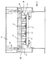
- Fig. 1 shows a device according to the invention generally designated by 10 for join a plurality of strips of materials 12a, 12b, 12c and 12d in cardboard corrugated.
- the strips 12a, 12b, 12c are composite strips formed each by a smooth strip and a wavy strip, while the 12d strip is just a smooth band.
- the device comprises a plurality of pressure 14, each being mounted to a frame 16 by means of a operating drive member 18 as well as support pins 20.
- a pressure plate 22 is mounted on the underside of the pressure 14 by means of support bars 24. Below the pressure plate 22 is mounted a back pressure plate 26 fixed to the frame 16, extending essentially in the horizontal direction and forming an essentially parallel pressure plate arrangement with the pressure plate 22 of the pressure unit 14.
- the pressure plate 22 and the back pressure plate 26 are each heatable arrangement, the heatable arrangement of the plate back pressure 26 not being described in more detail below.
- the backpressure plate 26 is heated preferably by a heat transfer fluid system.
- the pressure plate 22 is also heatable by a system carrying heat transfer fluid.
- the plate of pressure 22 is charged with heat-transfer fluid by supply lines and upper outlet 28 and 30 via fluid lines flexible 32.
- the strips of material 12a - 12d are guided by guide rollers 34 respectively guide elements 36 to a joining roller 38, where their sections with glue pressed against each other.
- the sticks to the contact points between the individual strips 12a - 12d is always liquid respectively wet, so that mutual adhesion bands is relatively small immediately behind the roll of junction 38, seen in a direction of advance A.
- Fig. 2 shows a detailed view of a pressure unit 14 according to the view in Fig. 1.
- the components already shown in Fig. 1 have the same references in FIG. 2.
- the pressure unit 14 is pivotally mounted to the support axis 20 by a support arm 40. Near the housing pivotable on the support axis 20, an operating lever 42 is fixed to the support arm 40 in orientation essentially perpendicular to the arm support 40.
- the actuating drive member 18 arranged as hydraulic force element is articulated to the operating lever 42 by through a hydraulic piston 44, a hydraulic cylinder 46 receiving the hydraulic piston 44 being articulated to the frame 16.
- a junction articulated to the terminal strip 24 is provided near the center of gravity S of it. Because of this measurement, the terminal strip 24 is always in an essentially horizontal position when moving of the support arm 40 around the support axis 20.
- the pressure plate 22 On the side of the terminal strip 24, which is remote from the support arm 40, the pressure plate 22 is mounted, the construction and connection of which to the terminal strip 24 are illustrated in the enlarged part VI.
- the plate of pressure 22 is mounted on the terminal strip 24 in such a way that its center of gravity lies in a plane essentially perpendicular to the direction of travel A, in which plane the center of gravity is S of the junction strip 24 as well as the axis of rotation of the junction articulated between the support arm 40 and the junction strip 24.
- a cover plate 48 is mounted on the upper face of the plate pressure 22 in such a way that it encloses an arch-shaped cavity 50 with the pressure plate 22.
- This cavity is accessible by pipes 52 and 52 ', which are connected to the upper supply line 28 and the upper outlet pipe 30 for the supply and exit, respectively, of heat transfer fluid by flexible fluid lines 32.32 '.
- pipes 52 and 52 ' are connected to the upper supply line 28 and the upper outlet pipe 30 for the supply and exit, respectively, of heat transfer fluid by flexible fluid lines 32.32 '.
- the guide faces 54 are provided, which allow the free entry of corrugated cardboard into the space between the pressure plate 22 and the back pressure plate 26 and its sliding in this space.
- an adjustment arrangement 56 is provided for at the articulated junction between the support arm 40 and the junction strip 24 allowing the resistance of the joint to be varied.
- the pressure plate 22 can be pivoted about the support axis 20 from the mutual contact position of pressure plate 22, corrugated cardboard P and back pressure plate 26 shown in FIG. 2 in a position removed from the carton corrugated P respectively of the back pressure plate 26 by the retraction of the hydraulic piston 44 in the hydraulic cylinder 46 and the associated pivoting of the operating lever 42 as well as of the support arm 40 connected with it.
- the pressure unit 14 thus allows positioning without gradations of the pressure plate 22 compared to the back pressure plate 26 and therefore a variation without gradations of pressure force and pressure applied to the cardboard wavy P.
- Fig. 3 shows a sectional view along line III-III in FIG. 1. Identical components have the same references as in Figs. 1 and 2. It is evident from FIG. 3, that four pressure units 14 1 , 14 2 , 14 3 , 14 4 are arranged on the support axis 20 one next to the other, an operating drive member 18 being respectively provided on the two axial ends of the axis of rotation 20 for the synchronous pivoting movement of the pressure units 14 1 , 14 2 , 14 3 , 14 4 around the support axis 20.
- the fluid supply line upper 28 supplying the four pressure units 14 1 - 14 4 with heat transfer fluid and being formed transverse to the direction of advance A oriented in the plane of FIG. 3.
- the supply line 28 passing transversely to the direction of advance A is itself connected to the supply lines 58, 58 ′ for the supply and for the outlet of heat transfer fluid.
- Fig. 4 shows a detailed perspective view of a pressure plate 22 provided with a cover plate 48.
- the direction of travel A is shown, in which a strip of corrugated cardboard spreads.
- the faces of guide 54 showing upwards.
- the cover plate 48 and pressure plate 22 are welded so waterproof. In the region inside the contour of the edges 60 of the plate cover 48, this and the pressure plate 22 are additionally joined by welding points 62.
- the cover plate 48 is lifted from the pressure plate 22 in the shape of an arch by an appropriate method of manufacturing, for example by the hydraulic expansion described above.
- FIG. 5 shows a section along line V-V in Fig. 4.
- the vault-shaped cavity 50 is formed between the plate of pressure 22 and the cover plate attached thereto.
- this cavity is crossed by the heat transfer fluid according to the arrows punctuated in FIG. 4.
- Fig. 6 shows two detailed views of alternative joining possibilities (Fig. 6a and 6b) of the pressure plate 22 and the terminal strip 24 corresponding to part VI in FIG. 2, the corrugated board having three wavy bands shown in Part VI being removed in Fig. 6.
- FIG. 6a a section of the junction strip 24 with several projections 64 on its face lower (of which only one shown in Fig. 6a), the projections corresponding to the arrangement on the one hand of the junction points 62 between the pressure plate 22 and cover plate 48.
- the terminal strip 24 is joined to the cover plate 48 and by the latter to the pressure plate 22 by the projection 64 at a welding point 62.
- the height h, by which the projection 64 projects from the face 66 of the terminal strip 24 is larger than the maximum bulge w of the cover plate 48, so that there has no place of mechanical contact and thus of thermal contact between the underside 66 of the terminal strip 24 and the cover plate 48 except on the undersides of the projections 64 in the area of the points of welding 62.
- Fig. 6a shows the thickness ratio between the thickness D of the pressure plate 22 and the thickness d of the cover plate 48.
- the thickness D of the pressure plate 22 amounts to at least twice the thickness d of the plate cover 48.
- Fig. 6b shows a second alternative according to the invention of the junction pressure plate 22 and terminal strip 24, components identical bearing the same references as in FIG. 6a.
- a threaded bolt 63 is welded to the cover plate 48 perpendicular to the pressure plate 22 at a welding point 62 on the side of the cover plate 48 showing towards the bar of junction 24.
- This threaded bolt 63 passes through a passage orifice 65 of a intermediate bar 67 resting on the crowns of the plate of cover 48.
- a hexagonal nut 69 is screwed on the section protruding from the threaded bolt 63, this nut pushing the intermediate bar 67 on the crowns of the cover plate 48.
- junction of the pressure plate 22 and the strip of junction 24 shown in FIG. 6b has the advantage that this junction is easy to do and to undo, so that the pressure plate 22 can be removed from the terminal strip 24 in a simple manner for reasons of assembly, troubleshooting and replacement.
- heat transfer is limited due to the relatively small total contact surface between the cover plate 48 and the intermediate bar 67.
- Fig. 7 shows various possibilities of a passage through several heatable pressure plates 22 arranged in the form of a matrix, the matrix arrangement 68 with lines R 1 - R 5 transverse to the direction of advance A and columns S 1 - S 4 in the direction of advance A being shown schematically in top view.
- the arrows inside the matrix arrangement 68 represent the directions of the passage of the heat transfer fluid through the pressure plates 22. Pressure plates not crossed by arrows are not charged with heat transfer fluid.
- Fig. 7a shows a matrix arrangement 68 composed of 20 pressure plates, the first three lines R 1 , R 2 , R 3 passing transversely to the direction of advance being charged with heat-transfer fluid and the lines R 4 , R 5 remaining without heating .
- the heat transfer fluid enters the pressure plate 22 1 arranged in the first place on the inlet side and gives heat there to the section of the strip of corrugated cardboard located at the below. Then the fluid flows from the pressure plate 22 1 into the pressure plate 22 2 , the heat-transfer fluid already having given up part of its thermal energy and thus having a lower temperature than when it entered the pressure plate 22 1 .
- the heat transfer fluid flows into the pressure plate 22 3 , the fluid having again a lower temperature when it passes through the plate pressure 22 3 only when entering the pressure plate 22 2 .
- the pressure plates of columns S 2 and S 3 are passed like those of column S 1 .
- a temperature gradient is thus obtained which decreases in the direction of advance A due to the generation of heat in the direction of flow of the fluid.
- Such coupling can be advantageous if the wet adhesive for bonding the strips of individual material to the strip of corrugated cardboard is to be returned from its liquid state to a state like a gel in the region of the first line R 1 of the plate pressure, which requires a strong supply of heat.
- the gelled adhesive is then cured, which requires a lower heat supply as a function of the rising distance from the inlet side end of the die arrangement, because the degree of hardening rises as a function of the rising distance from the end of entry side.
- Fig. 7b shows another coupling of the fluid system, to which heat transfer fluid has passed from the edge area (columns S 1 , S 4 ) of the matrix arrangement 68 transversely to the direction of advance A in the central area (columns S 2 , S 3 ) and left this zone.
- the coupling arrangement according to FIG. 7b leads to a heat supply profile transverse to the direction of advance A, a high heat flow being brought to the edge areas (columns S 1 , S 4 ) of the corrugated cardboard and the heat supply decreasing towards the center (columns S 2 , S 3 ) of the matrix arrangement 68.
- Such a coupling arrangement may for example be advantageous, if during the manufacture of wide strips of corrugated cardboard the degree of humidity in the edge areas exceeds that of the central area, so that a greater supply of heat is necessary in the areas of the edges to expel moisture.
Abstract
Description
La présente invention est relative à un arrangement de plaques de pression pour joindre une pluralité de bandes de matière, chacune comportant au moins une bande lisse ou/et au moins une bande ondulée, en bande de carton ondulé, de la colle étant appliquée au moins à des sections d'au moins une bande de matière, l' arrangement comportant une unité de pression équipée d'une plaque de pression et une plaque de contre-pression chauffable, entre lesquelles les bandes de matière à joindre sont passées, l'unité de pression avec sa plaque de pression étant rapprochable respectivement éloignable de la plaque de contre-pression.The present invention relates to an arrangement of pressure plates to join a plurality of strips of material, each comprising at at least one smooth strip or / and at least one wavy strip, in strip of corrugated board, glue being applied to at least sections of at least at least one strip of material, the arrangement comprising a unit of pressure fitted with pressure plate and back pressure plate heatable, between which the strips of material to be joined are passed, the pressure unit with its pressure plate being reconcilable respectively removable from the back pressure plate.
Des tels arrangements de plaques de pression sont connus de la technique
antérieure. Un tel arrangement est par exemple décrit à la page 10 de
l'imprimé "The Double-Facer Group", no. de l'imprimé 2(694GB)0,5 de
l'entreprise Peters Maschinenfabrik GmbH. Dans cet arrangement, les
bandes de matière pourvues de colle sont supportées sur la plaque de
contre-pression chauffable et sont appuyées l'une contre l'autre du côté
opposé par des plaques de pression. L'amenée de chaleur par la plaque de
contre-pression chauffable accelère le durcissement de la colle. Par contre,
avec des bandes de carton ondulé multi-couches, c'est-à-dire des bandes
de carton ondulé comportant deux ou plus de bandes ondulées (par exemple
du carton ondulé double-face), il en résulte le problème que la température
dans le carton ondulé diminue avec la distance de la plaque de contre-pression
chauffée, de sorte qu'un séchage complet des lieux de collage
écartés de la plaque de contre-pression dure plus longtemps. Pour tenir
compte de ce problème, il est nécessaire, avec des bandes de matière en
mouvement, de diminuer la vitesse de mouvement de façon correspondante,
pour permettre un traitement de chaleur suffisamment long des lieux de
collage, ou il est nécessaire de dimensionner la plaque de contre-pression
chauffable avec une longueur correspondante, ou il est nécessaire,
d'augmenter la quantité de chaleur amenée par unité de temps de façon
correspondante. En plus, les dépenses du traitement de chaleur nécessaire
montent avec l'épaisseur du carton ondulé et/ou avec le grammage (poids
par surface du carton ondulé). Bien entendu la réduction de la vitesse de
mouvement de la bande de matière ainsi que l'extension de l'arrangement
ainsi que l'augmentation de la quantité de chaleur amenée par la plaque de
contre-pression par unité de temps sont limitées au niveau économique et
pratique.Such arrangements of pressure plates are known in the art
anterior. Such an arrangement is for example described on
C'est pourquoi la présente invention a pour objet de fournir un arrangement de plaques de pression du type générique, qui permet d'accélérer le durcissement de la colle en maintenant la même vitesse de mouvement, la même longueur de l' arrangement et la même amenée de chaleur par la plaque de contre-pression.This is why the object of the present invention is to provide an arrangement pressure plates of the generic type, which accelerates the hardening of the glue while maintaining the same speed of movement, the same length of the arrangement and the same supply of heat by the back pressure plate.
Dans un arrangement de plaques de pression du type générique, cet objet est accompli en ce que la plaque de pression est également formée de façon chauffable.In an arrangement of generic type pressure plates, this object is accomplished in that the pressure plate is also formed so heatable.
Par un chauffage de la plaque de contre-pression ainsi que de la plaque de pression, la chaleur peut être amenée au carton ondulé des deux côtés, de sorte que d'une part l'amenée de chaleur totale peut être augmentée en maintenant le même débit d'amenée de chaleur par la plaque de contre-pression, et d'autre part un profil de temperature uniforme peut être obtenu tout au long de l'épaisseur du carton ondulé. Ainsi, d'abord la gélification et puis le durcissement de la colle sont rendus plus uniformes tout au long de l'épaisseur du carton ondulé. Par conséquent, il n'y a plus de délai du durcissement en fonction de la distance montante de la plaque de contre-pression. A cause du durcissement plus uniforme tout au long de l'épaisseur du carton ondulé, la durée du traitement nécessaire pour le durcissement peut être réduite à l'aide de l'arrangement de plaques de pression selon l'invention. Par conséquent, il en résultent des temps de passage moins longs lors de la fabrication du carton ondulé respectivement une plus petite longueur minimale nécessaire de l' arrangement de plaques de pression, si la bande de carton ondulé est en mouvement. Ceci est aussi valable pour des épaisseurs grandes du carton ondulé et/ou des grammages grands.By heating the back pressure plate as well as the pressure, heat can be brought to the corrugated board on both sides, so that on the one hand the total heat supply can be increased by maintaining the same heat supply rate through the back pressure plate, and on the other hand a uniform temperature profile can be obtained throughout the thickness of the corrugated cardboard. So, first the gelation and then the hardening of the glue are made more uniform throughout of the thickness of the corrugated cardboard. Therefore, there is no longer a delay of hardening as a function of the rising distance from the back pressure plate. Because of the more uniform hardening throughout the thickness corrugated cardboard, the duration of treatment required for curing can be reduced using the arrangement of pressure plates according to the invention. Consequently, this results in less passage times long during the production of corrugated board respectively a smaller minimum required length of pressure plate arrangement, if the strip of corrugated cardboard is moving. This also applies to large thicknesses of corrugated cardboard and / or large grammages.
La chauffabilité de la plaque de pression peut être obtenue des façons différentes. Par exemple, des fils de chauffage permettant un chauffage résistif de la plaque de pression peuvent être prévus dans ou à la plaque de pression. Pourtant, de préférence il est prévu qu'une plaque de couverture est arrangée à la plaque de pression sur son côté detourné de la plaque de contre-pression, la plaque de couverture et la plaque de pression entourant une cavité alimentable d'un fluide caloportant. Ceci permet de chauffer la plaque de pression à l'aide de moyens simples, qui sont habituellement disponibles de toute façon à l'endroit d'opération à cause du chauffage similaire de la plaque de contre-pression. Par conséquent, on peut aussi envisager un rattrapage d'installations existantes. Comme fluide caloportant on peut prévoir des substances diverses comme par exemple des huiles hydrauliques caloportantes. Pourtant, de préférence de la vapeur d'eau est utilisée comme fluide caloportant à cause de sa mise à disposition peu coûteuse, sa non-pollution etc.The heatability of the pressure plate can be obtained in the following ways: different. For example, heating wires for heating resistive pressure plate can be provided in or at the pressure plate pressure. However, preferably it is expected that a cover plate is arranged with the pressure plate on its side turned away from the plate back pressure, the cover plate and the surrounding pressure plate a cavity which can be supplied with a heat transfer fluid. This will heat the pressure plate using simple means, which are usually anyway available at the place of operation because of the heating similar to the back pressure plate. Therefore, we can also consider retrofitting existing facilities. As heat transfer fluid we can provide various substances such as oils heat transfer hydraulics. However, preferably water vapor is used as a heat transfer fluid because of its availability expensive, its non-pollution etc.
La plaque de pression et la plaque de couverture peuvent être fabriquées des matériaux divers, par exemple en fonction du fluide caloportant utilisé. Il est possible de les fabriquer de matière synthétique ou de plaques couvertes de matière synthétique. Pourtant, de préférence il est prévu que la plaque de pression ou/et la plaque de couverture est respectivement sont fabriquée(s) de métal, de préférence d'acier antirouille. Ceci assure un arrangement particulièrement robuste avec facilité d'entretien et des bons charactéristiques de conduction thermique.Pressure plate and cover plate can be made various materials, for example depending on the heat transfer fluid used. It is possible to make them from synthetic material or plates covered with synthetic material. However, preferably it is expected that the pressure plate or / and the cover plate is respectively are made of metal, preferably anti-rust steel. This ensures a particularly robust arrangement with easy maintenance and good thermal conduction characteristics.
Pour assurer une application uniforme de pression sur la bande de carton ondulé plane par la plaque de pression, il est prévu, que l'épaisseur de paroi de la plaque de pression est entre environ 3 mm et environ 5 mm, de préférence environ 4 mm. Comme la plaque de couverture n'est pas exposée à des charges mécaniques aussi grandes, son épaisseur de paroi peut être considérablement plus petite, et de préférence il est prévu, que l'épaisseur de paroi de la plaque de couverture est entre 0,5 mm et environ 2 mm, de préférence environ 1,5 mm. En outre, des telles épaisseurs de paroi permettent un contrôle thermique relativement "rapide en réaction" de la plaque de pression à chauffer, parce que les volumes à chauffer peuvent rester limités.To ensure uniform application of pressure on the cardboard strip corrugated plane by the pressure plate, it is expected that the wall thickness pressure plate is between about 3 mm and about 5 mm, from preferably about 4 mm. Since the cover plate is not exposed to such large mechanical loads, its wall thickness may be considerably smaller, and preferably it is expected, that the wall thickness of the cover plate is between 0.5 mm and approximately 2 mm, preferably about 1.5 mm. In addition, such thicknesses of wall allow relatively "rapid reaction" thermal control of the pressure plate to be heated, because the volumes to be heated can stay limited.
Pour le chargement d'un fluide caloportant dans la cavité enfermée entre la plaque de pression et la plaque de couverture, il est prévu, que la cavité peut être reliée à au moins une conduite d'amenée de fluide et au moins une conduite de sortie de fluide. Ceci permet l'intégration du système de fluide de la plaque de pression chauffable dans un système de fluide supérieur, de sorte que le fluide caloportant peut couler à travers la conduite d'amenée de fluide, la cavité enfermée entre la plaque de pression et la plaque de couverture, et la conduite de sortie de fluide. En vue d'un mouvement de l'unité de pression avec sa plaque de pression par rapport à la plaque de contre-pression, les conduites d'amenée de fluide et les conduites de sortie de fluide sont avantageusement formées de façon flexible.For charging a heat transfer fluid into the cavity enclosed between the pressure plate and cover plate, it is expected, that the cavity can be connected to at least one fluid supply line and at least one fluid outlet line. This allows integration of the fluid system of the heatable pressure plate in a superior fluid system, so that the heat transfer fluid can flow through the supply line fluid, the cavity enclosed between the pressure plate and the cover, and the fluid outlet line. In view of a movement of the pressure unit with its pressure plate relative to the pressure plate back pressure, fluid supply lines and output lines fluid are advantageously formed in a flexible manner.
Pour permettre un branchement facile des conduites d'amenée de fluide et des conduites de sortie de fluide à l'unité de pression, il est prévu, qu'au moins deux tubulures servant à la liaison aux conduites de fluide sont arrangées à la plaque de couverture. En cas d'une plaque de couverture métallique, ces tubulures peuvent être soudées directement à celle-ci. Le cas échéant, il est également possible de prévoir des soupapes de surpression ou d'autres éléments pneumatiques ou hydrauliques à la plaque de couverture.To allow easy connection of the fluid supply lines and from the fluid outlet lines to the pressure unit, it is intended that at least two pipes used for connection to the fluid lines are arranged on the cover plate. In case of a cover plate metal, these pipes can be welded directly to it. The if necessary, it is also possible to provide relief valves overpressure or other pneumatic or hydraulic elements to the plate cover.
Pour former la cavité entre la plaque de pression et la plaque de couverture, il est prévu, que la plaque de couverture est jointe de façon étanche, de préférence au niveau de son contour extérieur, à la plaque de pression. Cette jonction étanche peut être achevée par collage ou, dans le cas préféré d'une plaque de pression métallique et d'une plaque de couverture métallique, par soudage, la dernière possibilité représentant une jonction étanche particulièrement robuste et fiable entre la plaque de pression et la plaque de couverture.To form the cavity between the pressure plate and the cover plate, it is expected that the cover plate is sealed, preferably at its outer contour, to the pressure plate. This waterproof junction can be completed by gluing or, in the preferred case a metal pressure plate and a cover plate metallic, by welding, the last possibility representing a junction particularly robust and reliable seal between the pressure plate and the cover plate.
Comme mesure pour augmenter la stabilité et la rigidité de la plaque de pression chauffable, il est prévu, que la plaque de couverture est jointe à la plaque de pression à une pluralité de points, qui sont de préférence distribués de façon uniforme, la cavité entre ces points de jonction ayant la forme d'une voûte. Une telle jonction de la plaque de pression à la plaque de couverture permet en outre une fabrication particulièrement facile de la cavité comme il sera décrit en ce qui suit. A savoir, il est possible de poser une plaque de couverture essentiellement plane sur la plaque de pression également essentiellement plane, de joindre la plaque de couverture au niveau de son contour extérieur à la plaque de pression de façon étanche et de prévoir en plus des points de jonction individuels dans la zone à l'intérieur du contour extérieur. En cas d'une plaque de pression métallique et d'une plaque de couverture métallique, la jonction se fait de préférence par soudage ou soudage par point. Après une telle jonction, un fluide hydraulique, de préférence de l'eau, est pressé sous haute pression entre la plaque de pression et la plaque de couverture adjacente par des conduites d'amenée et des conduites de sortie appropriées, comme par exemple les tubulures déjà décrites. A cause de l' épaisseur de paroi de la plaque de couverture plus faible par rapport à la plaque de pression, la haute pression du fluide hydraulique mène à des déformations plastiques de la plaque de couverture en forme de bosses, de sorte qu'une cavité continue en forme d'une voûte se forme. Un support approprié de la plaque de pression évite, que celle-ci aussi se déforme de manière plastique. Ensuite on peut enlever le fluide hydraulique de la cavité et passer à un usinage ultérieur de la plaque de pression.As a measure to increase the stability and rigidity of the plate pressure heatable it is expected that the cover plate is attached to the pressure plate at a plurality of points, which are preferably uniformly distributed, the cavity between these junction points having the shape of a vault. Such a junction from the pressure plate to the plate moreover allows a particularly easy manufacture of the cavity as will be described below. Namely, it is possible to ask an essentially flat cover plate on the pressure plate also essentially flat, attach the cover plate to the level of its contour outside the pressure plate in a leaktight manner and to provide in addition individual junction points in the area to inside the outside outline. In case of a metal pressure plate and a metal cover plate, the junction is preferably made by welding or spot welding. After such a junction, a fluid hydraulic, preferably water, is pressed under high pressure between the pressure plate and the adjacent cover plate by pipes supply lines and suitable outlet lines, such as tubing already described. Because of the wall thickness of the plate lower coverage compared to pressure plate, high pressure of hydraulic fluid leads to plastic deformations of the plate bump-like cover, so that a continuous cavity in shape a vault is formed. Proper support of the pressure plate avoids, that this one also deforms in a plastic way. Then we can remove hydraulic fluid from the cavity and move on to further machining the pressure plate.
En général, le positionnement des bandes de matière entre la plaque de pression et la plaque de contre-pression se fait ou par un mouvement discontinu ou de préférence par un mouvement continu des bandes de matière. Pour éviter que le mouvement de la bande de carton ondulé soit affecté par des joints de la bande de matière, appelés raccordements, il est prévu, que la plaque de pression est équipée d'une face de guidage sur le côté de l'amenée de la bande de matière et, si souhaité, également sur le côté de la sortie de la bande de matière. Ceci permet au joint d'entrer librement sous la plaque de pression et de couler sous celle-ci et empêche des bourrages causés par des sections de la bande de matière retournées dans la zone du joint (zone du raccordement).In general, the positioning of the material strips between the plate pressure and the back pressure plate is done or by a movement discontinuous or preferably by continuous movement of the strips of matter. To prevent the movement of the corrugated cardboard strip from being affected by joints of the material strip, called connections, it is provided, that the pressure plate is equipped with a guide face on the side of the material web feed and, if desired, also on the side of the material web outlet. This allows the joint to enter freely under the pressure plate and to flow under it and prevents jams caused by sections of the web of material returned in the joint area (connection area).
En outre, pour permettre un positionnement variable de la plaque de pression, il est prévu selon l'invention, que l'unité de pression comporte un support de la plaque de pression et un dispositif de manoeuvre pour rapprocher la plaque de pression à la plaque de contre-pression respectivement pour éloigner la plaque de pression de la plaque de contre-pression. En vue d'une application uniforme de pression sur le carton ondulé à l'aide du support de la plaque de pression, il est prévu selon l'invention, que le support de la plaque de pression comporte au moins une barrette de support, qui est jointe à la plaque de pression, de préférence par l'intermédiaire de la plaque de couverture. Cette mesure permet un montage suffisamment stable de la plaque de pression au support de la plaque de pression. In addition, to allow variable positioning of the plate pressure, it is provided according to the invention, that the pressure unit comprises a support of the pressure plate and an operating device for move the pressure plate closer to the back pressure plate respectively to move the pressure plate away from the back pressure plate. For uniform application of pressure on corrugated board using the support of the pressure plate, it is provided according to the invention, that the support of the pressure plate comprises at least one bar of support, which is attached to the pressure plate, preferably by through the cover plate. This measurement allows mounting sufficiently stable from the pressure plate to the support of the pressure plate pressure.
De préférence la au moins une barrette de support comporte une pluralité de saillies, qui sont jointes à la plaque de couverture à une part des points de la jonction à la plaque de pression. Il est particulièrement avantageux de prévoir des saillies à la barrette de support, si la cavité enfermée entre la plaque de pression et la plaque de couverture est formée en forme de voûte à cause de sa fabrication par expansion hydraulique, comme il a été décrit dessus. Dans ce cas il est possible de limiter les lieux de jonction entre la barrette de support et la plaque de pression respectivement la plaque de couverture aux ou à une part des points de jonction, de sorte que la forme de la cavité en forme de voûte n'est pas changée lors du montage de la barrette de support.Preferably the at least one support strip has a plurality protrusions, which are attached to the cover plate at a share of the points from the junction to the pressure plate. It is particularly advantageous to provide projections on the support bar, if the cavity enclosed between the pressure plate and the cover plate is shaped like an arch because of its manufacture by hydraulic expansion, as described above. In this case it is possible to limit the places of junction between the support bar and pressure plate respectively the plate coverage at or at a part of the junction points, so that the shape of the vault-shaped cavity is not changed when mounting the support strip.
Avec une telle jonction de la plaque de pression à la barrette de support par l'intermédiaire de saillies jointes aux points de jonction, il est particulièrement avantageux, s'il n'y a pas d'autre contact mécanique entre la barrette de support et la plaque de couverture sauf par l'intermédiaire des saillies. Autrement dit, il est prévu selon l'invention, que la au moins une barrette de support est disposée entre ses saillies de jonction avec un écart de la plaque de couverture. Ceci évite un contact thermique entre la plaque de couverture et la barrette de support, par lequel de la chaleur peut être dissipée. Ainsi l'écart sert d'isolation entre la barrette de support et la plaque de couverture.With such a junction of the pressure plate to the support strip by through projections attached to the junction points it is particularly advantageous, if there is no other mechanical contact between the support strip and the cover plate except through the protrusions. In other words, it is provided according to the invention, that the at least one support strip is arranged between its junction projections with a gap of the cover plate. This avoids thermal contact between the plate cover and the support strip, through which heat can be dissipated. Thus the gap serves as insulation between the support strip and the cover plate.
Comme alternative à une jonction entre la plaque de pression et la barrette de support à l'aide d'une pluralité de saillies, il est prévu, que des boulons filetés sont fixés, essentiellement perpendiculairement à la plaque de pression, à la plaque de couverture, de préférence à une partie des points de jonction à la plaque de pression, par lesquels la au moins une barrette de support est fixée, c'est-à-dire vissée, directement ou par l'intermédiaire d'au moins une barrette intermédiaire, à la plaque de pression. Une telle jonction entre la plaque de pression respectivement la plaque de couverture et la barrette de support à l'aide de boulons filetés est particulièrement facile à monter, de sorte que la plaque de pression peut facilement être éloignée de la barrette de support ou être montée à celle-ci, en particulier pour une réparation et/ou un remplacement.As an alternative to a junction between the pressure plate and the bar support using a plurality of protrusions, it is expected that bolts threaded are fixed, essentially perpendicular to the plate pressure, to the cover plate, preferably at part of the points of connection to the pressure plate, by which the at least one strip of support is fixed, i.e. screwed, directly or by means of minus an intermediate bar, to the pressure plate. Such a junction between the pressure plate respectively the cover plate and the support bar using threaded bolts is particularly easy to mount, so that the pressure plate can easily be moved away from the support bar or be mounted to it, in particular for a repair and / or replacement.
En vue d'un mouvement facile de la plaque de pression par rapport à la plaque de contre-pression, il est prévu selon l'invention, que le dispositif de manoeuvre comporte un arrangement de leviers articulé à un bâti ainsi qu'un organe d'entraínement de manoeuvre joint à l'arrangement de leviers et comportant de préférence au moins un arrangement de vérin/piston actionnable à l'aide d'un fluide. L'organe d'entraínement de manoeuvre peut être actionnable de façon hydraulique ou pneumatique. Un tel dispositif est insensible quant à son milieu d'opération et assure une haute sécurité opératoire en exigeant peu d'entretien.For easy movement of the pressure plate relative to the back pressure plate, it is provided according to the invention, that the device operation includes an arrangement of levers articulated to a frame as well that an operating drive member attached to the lever arrangement and preferably comprising at least one cylinder / piston arrangement actuable using a fluid. The drive trainer can be actuated hydraulically or pneumatically. Such a device is insensitive to its operating environment and ensures high security requiring little maintenance.
A cause de la diversité de produits de carton ondulé, par exemple quant à l'épaisseur du carton ondulé à fabriquer ou la forme de la bande ondulée respectivement les bandes ondulées enfermées dedans, il est souhaitable que tous les produits puissent être fabriqués avec un seul arrangement de plaques de pression. A cet effet il est avantageux que la position de la plaque de pression par rapport à la plaque de contre-pression ainsi que la pression soient variables. Pour atteindre ce but avec des moyens simples, il est prévu selon l'invention, que la force de manoeuvre de l'organe d'entraínement de manoeuvre est variable, de préférence sans gradations. En outre, il est de préférence prévu dans ce contexte, que l'arrangement de leviers est articulé à la au moins une barrette de support. Par une telle jonction articulée, on peut obténir une application de pression uniforme sur toute la surface de contact entre la bande de carton ondulé et la plaque de pression indépendent des variations de la position respectivement de la force de manoeuvre de l'organe d'entraínement de manoeuvre.Because of the diversity of corrugated products, for example the thickness of the corrugated cardboard to be manufactured or the shape of the corrugated strip respectively the corrugated strips enclosed in it, it is desirable that all products can be produced with a single arrangement of pressure plates. For this purpose it is advantageous that the position of the pressure plate relative to the back pressure plate as well as the pressure are variable. To achieve this goal with simple means, according to the invention, it is provided that the operating force of the member maneuvering training is variable, preferably without gradations. In addition, it is preferably provided in this context, that the arrangement of levers is articulated to the at least one support bar. By such articulated junction, it is possible to obtain a uniform pressure application on the entire contact surface between the strip of corrugated cardboard and the plate pressure independent of the variations of the position respectively of the operating force of the operating drive member.
En plus, l'invention est relative à un dispositif pour joindre une pluralité de bandes de matière, comportant une pluralité d' arrangements de plaques de pression selon la description ci-dessus. Selon l'invention, les arrangements de plaques de pression dans un tel dispositif sont arrangés en forme de matrice en direction d'avancement des bandes de matière ou/et transversalement à cette direction d'avancement l'un voisin à l'autre. Un arrangement en matrice en direction d'avancement et transversal à celle-ci de plusieurs arrangements de plaques de pression chauffables selon l'invention permet donc un traitement de la bande de carton ondulé sur une grande surface et des deux côtés et, selon les besoins, variable avec résolution spatiale en pression et en amenée de chaleur. Ceci est avantageux en vue d'une grande capacité de production.In addition, the invention relates to a device for joining a plurality of strips of material, comprising a plurality of arrangements of sheet plates pressure as described above. According to the invention, the arrangements pressure plates in such a device are arranged in the form of matrix in the direction of advancement of the strips of material or / and transverse to this direction of advance, one adjacent to the other. A matrix arrangement in the direction of advancement and transverse to it of several arrangements of heatable pressure plates according to the invention therefore allows a treatment of the strip of corrugated cardboard on a large area and on both sides and, as required, variable with spatial resolution in pressure and heat supply. this is advantageous in view of a large production capacity.
Pour assurer une opération avantageuse du dispositif selon l'invention aussi sous des points de vue économiques, il est prévu, qu'au moins une part des arrangements de plaques de pression est chauffable à l'aide d'un arrangement de chauffage commun, de préférence étant chargeable de fluide caloportant en commun. Ceci signifie, que plusieurs arrangements de plaques de pression sont respectivement associés à un arrangement de chauffage supérieur et alimenté par celui-ci. En cas d'un arrangement de chauffage avec un système qui transporte du fluide caloportant, le fluide caloportant peut couler à travers les arrangements individuels de plaques de pression en ordres différents déterminés par certains "couplages". Par exemple, il est prévu comme alternative selon l'invention, que le fluide caloportant coule successivement à travers les arrangements de plaques de pression associés à un arrangement de chauffage commun (supérieur) (couplage en série). Ainsi la température baisse en direction d'écoulement, parce que le fluide caloportant cède de la chaleur à chaque arrangement de plaques de pression traversé et ses environs le long de son chemin d'écoulement.To ensure an advantageous operation of the device according to the invention also from an economic point of view, it is expected that at least some of the pressure plate arrangements is heatable using a common heating arrangement, preferably being chargeable with heat transfer fluid in common. This means that several arrangements of pressure plates are respectively associated with an arrangement of upper heating and powered by it. In the event of an arrangement of heating with a system that transports heat transfer fluid, the fluid coolant can flow through the individual arrangements of plates of pressure in different orders determined by certain "couplings". Through example, it is provided as an alternative according to the invention, that the fluid coolant flows successively through the plate arrangements of pressure associated with a common (upper) heating arrangement (coupling in series). So the temperature drops in the direction of flow, because the heat transfer fluid gives off heat with each arrangement of pressure plates crossed and its surroundings along its path of flow.
Comme une autre alternative de couplage, le fluide caloportant peut couler à travers les arrangements de plaques de pression associés à un arrangement de chauffage commun en parallèle (couplage en parallèle). As another coupling alternative, the heat transfer fluid can flow through the pressure plate arrangements associated with a common heating arrangement in parallel (parallel coupling).
Avec un tel arrangement, chaque arrangement de plaques de pression est traversé par du fluide de la même température, de sorte que ces arrangements aussi ont essentiellement la même température.With such an arrangement, each arrangement of pressure plates is crossed by fluid of the same temperature, so these arrangements also have essentially the same temperature.
Selon ce qui précède, des différents profils d'amenée de chaleur peuvent être ajustés dans un arrangement de plaques de pression en forme de matrice à l'aide de couplages différents (couplage en série, couplage en parallèle), de sorte qu'il est par exemple possible d'ajuster une température plus haute dans la zone des bords parallèles à la direction d'avancement que dans la zone centrale. Ceci est avantageux, parce que lors du séchage de la colle de l'humidité est chassée, que doit être dissipée le long des nervures des bandes ondulées, de sorte que l'humidité relative est plus grande dans la zone des bords que dans la zone centrale. Cependant, des gradients de température en direction d'avancement ainsi que des gradients de température de surface sont également possible. En plus, il est possible de ne pas chauffer des plaques de pression individuelles de l'arrangement de matrice respectivement de ne pas les charger du fluide caloportant. Les arrangements différents de couplage permettent donc une adaptation directe des arrangements de plaques de pression au produit de carton ondulé à fabriquer, par exemple en fonction du nombre des bandes ondulées, du grammage utilisé etc.According to the above, different heat supply profiles can be fitted into an arrangement of pressure plates in the form of matrix using different couplings (coupling in series, coupling in parallel), so that it is for example possible to adjust a temperature higher in the area of the edges parallel to the direction of travel than in the central area. This is advantageous, because when drying the moisture glue is removed, which must be dissipated along the ribs wavy bands, so that the relative humidity is greater in the edge area only in the central area. However, gradients of forward direction temperature as well as gradients of surface temperature are also possible. In addition, it is possible to do not heat individual pressure plates of the arrangement matrix respectively not to charge them with the heat transfer fluid. The different coupling arrangements therefore allow adaptation direct pressure plate arrangements to the carton product corrugated to manufacture, for example according to the number of strips wavy, the grammage used etc.
Les plaques de pression individuelles peuvent être manoeuvrées par rapport à la plaque de contre-pression à l'aide de dispositifs de manoeuvre individuels ou, en cas d'un couplage mécanique mutuel, à l'aide d'organes d'entraínement de manoeuvre associés à plusieurs plaques de pression.Individual pressure plates can be operated relative to to the back pressure plate using operating devices individual or, in case of mutual mechanical coupling, using organs maneuvering training associated with several pressure plates.
En ce qui suit, l'invention sera illustrée plus précisement à l'aide de quelques exemples de réalisation se référant aux dessins annexés.
- Fig. 1
- montre une vue de côté d'une section du côté de l'entrée de la bande de matière d'un dispositif pour joindre une pluralité de bandes de matière selon l'invention;
- Fig. 2
- montre une vue en détail d'une unité de pression avec son organe d'entraínement de manoeuvre à la Fig. 1;
- Fig. 3
- montre une vue en coupe du arrangement selon l'invention selon la ligne III-III à la Fig. 1;
- Fig. 4
- montre une vue détaillée en perspective d'une plaque de pression et d'une plaque de couverture avec des tubulures;
- Fig. 5
- montre une vue en coupe de la plaque de pression selon l'invention selon la ligne V-V à la Fig. 4;
- Fig. 6
- montre des vues détaillées de la zone autour d'un point de jonction correspondant à la partie VI à la Fig. 2,
- Fig. 6a
- montrant une jonction entre la barrette de support et la plaque de pression par l'intermédiaire d'une saillie et
- Fig. 6b
- montrant une jonction entre la plaque de pression et la barrette de support par l'intermédiaire d'un boulon fileté; et
- Fig. 7
- montre des représentations schématiques différentes des couplages à l'intérieur d'une matrice de plaques de pression,
- Fig. 7a
- montrant un couplage en série traversé en direction d'avancement et
- Fig. 7b
- montrant un couplage en série symétrique traversé transversalement à la direction d'avancement.
- Fig. 1
- shows a side view of a section on the entry side of the strip of material of a device for joining a plurality of strips of material according to the invention;
- Fig. 2
- shows a detailed view of a pressure unit with its operating drive member in FIG. 1;
- Fig. 3
- shows a sectional view of the arrangement according to the invention according to line III-III in FIG. 1;
- Fig. 4
- shows a detailed perspective view of a pressure plate and a cover plate with pipes;
- Fig. 5
- shows a sectional view of the pressure plate according to the invention along the line VV in FIG. 4;
- Fig. 6
- shows detailed views of the area around a junction point corresponding to Part VI in Fig. 2,
- Fig. 6a
- showing a junction between the support bar and the pressure plate by means of a projection and
- Fig. 6b
- showing a junction between the pressure plate and the support bar via a threaded bolt; and
- Fig. 7
- shows different schematic representations of the couplings inside a matrix of pressure plates,
- Fig. 7a
- showing a coupling in series crossed in the direction of advancement and
- Fig. 7b
- showing a symmetrical series coupling crossed transversely to the direction of advance.
Fig. 1 montre un dispositif selon l'invention désigné en général par 10 pour
joindre une pluralité de bandes de matières 12a, 12b, 12c et 12d en carton
ondulé. Les bandes 12a, 12b, 12c sont des bandes composées formées
chacune par une bande lisse et une bande ondulée, tandis que la bande 12d
n'est qu' une bande lisse. Le dispositif comporte une pluralité d'unités de
pression 14, chacune étant montée à un bâti 16 par l'intermédiaire d'un
organe d'entraínement de manoeuvre 18 ainsi que des axes de support 20.
Une plaque de pression 22 est montée à la face inférieure de l'unité de
pression 14 par l'intermédiaire de barrettes de support 24. Au dessous de
la plaque de pression 22 est montée une plaque de contre-pression 26 fixée
au bâti 16, s'étendant essentiellement en direction horizontale et formant
un arrangement de plaques de pression essentiellement parallèle avec la
plaque de pression 22 de l'unité de pression 14.Fig. 1 shows a device according to the invention generally designated by 10 for
join a plurality of strips of
La plaque de pression 22 et la plaque de contre-pression 26 sont chacune
agencées de façon chauffable, l'agencement chauffable de la plaque de
contre-pression 26 n'étant pas décrit plus détaillé en ce qui suit. A noter
uniquement que le chauffage de la plaque de contre-pression 26 se fait de
préférence par un système de fluide caloportant. Dans cet exemple de
réalisation, la plaque de pression 22 est également chauffable par un
système transportant du fluide caloportant. A cet effet, la plaque de
pression 22 est chargée de fluide caloportant par des conduites d'amenée
et de sortie supérieures 28 et 30 par l'intermédiaire de conduites de fluide
flexibles 32.The
Lors de l'opération, les bandes de matière 12a - 12d, dont au moins de
sections près des cimes d'ondulation dégagées ont été couvertes de colle,
de préférence immédiatement avant l'entrée sur le côté d'entrée du
dispositif 10, sont guidées par des rouleaux de guidage 34 respectivement
des éléments de guidage 36 à un rouleau de jonction 38, où leurs sections
pourvues de colle sont appuyées l'une contre l'autre. A cet instant-là, la
colle aux lieux de contact entre les bandes individuelles 12a - 12d est
toujours liquide respectivement humide, de sorte que l'adhésion mutuelle
des bandes est relativement faible immédiatement derrière le rouleau de
jonction 38, vu dans une direction d'avancement A. Pour obténir du carton
ondulé, dont les bandes de matière individuelles 12a - 12d formant ce
carton ont une adhésion mutuelle suffisamment forte, il est nécessaire
d'appliquer de la pression au carton ondulé dans la section du dispositif 10
suivant le rouleau de jonction 38 en direction d'avancement A et d'amener
en même temps de la chaleur pour accélérer la gélification et le
durcissement suivant de la colle. Ceci se fait par la coopération des unités
de pression 14 avec des plaques de pression 22 et la plaque de contre-pression
26. On remarquera que de préférence les trois premières unités de
pression 14, 14', 14'' suivant le rouleau de jonction 38 en direction
d'avancement A sont agencées de façon chauffable, parce que la colle à
tant gélifiée respectivement durcie après la troisième unité de pression 14'',
que l'amenée de chaleur ultérieure des deux côtés par l'unité de pression
chauffable 14 et la plaque de contre-pression chauffable 26 n'est plus
nécessaire. Pourtant, en fonction de la vitesse de mouvement souhaitée du
carton ondulé et le genre du produit de carton ondulé à fabriquer, plus ou
moins d'unités de pression 14 peuvent être agencées de façon chauffable
en direction d'avancement A.During the operation, the strips of material 12a - 12d, at least of which
sections near the undulating peaks were covered with glue,
preferably immediately before entry on the entry side of the
La Fig. 2 montre une vue en détail d'une unité de pression 14 selon la vue
d'ensemble à la Fig. 1. Les composants déjà montrés en Fig. 1 ont les
mêmes références à la Fig. 2. L'unité de pression 14 est montée pivotable
à l'axe de support 20 par un bras de support 40. Près du logement
pivotable sur l'axe de support 20, un levier de manoeuvre 42 est fixé au
bras de support 40 en orientation essentiellement perpendiculaire au bras
de support 40. L'organe d'entraínement de manoeuvre 18 agencé comme
élément de force hydraulique est articulé au levier de manoeuvre 42 par
l'intermédiaire d'un piston hydraulique 44, un cylindre hydraulique 46
recevant le piston hydraulique 44 étant articulé au bâti 16.Fig. 2 shows a detailed view of a
Au bout du bras de support 40 éloigné de l'axe du support, une jonction
articulée à la barrette de jonction 24 est prévue près du centre de gravité
S de celle-ci. A cause de cette mesure, la barrette de jonction 24 se trouve
toujours dans une position essentiellement horizontale lors d'un mouvement
du bras de support 40 autour de l'axe de support 20.At the end of the
Sur le côté de la barrette de jonction 24, qui est éloigné du bras de support
40, est montée la plaque de pression 22, dont la construction et la jonction
à la barrette de jonction 24 sont illustrées dans la partie agrandie VI. Dans
la description suivante des Fig. 6a et 6b, on se réfère de façon plus detaillée
à cette partie agrandie. Cependant on remarquera ici, que la plaque de
pression 22 est montée à la barrette de jonction 24 de telle façon, que son
centre de gravité se trouve dans un plan essentiellement perpendiculaire à
la direction d'avancement A, dans quel plan se trouve le centre de gravité
S de la barrette de jonction 24 ainsi que l'axe de rotation de la jonction
articulée entre le bras de support 40 et la barrette de jonction 24.On the side of the
Une plaque de couverture 48 est montée à la face supérieure de la plaque
de pression 22 de telle façon, qu'elle enferme une cavité en forme de voûte
50 avec la plaque de pression 22. Cette cavité est accessible par des
tubulures 52 et 52', qui sont reliées à la conduite d'amenée 28 supérieure
et la conduite de sortie 30 supérieure pour l'amenée et la sortie,
respectivement, de fluide caloportant par des conduites de fluide flexibles
32,32'. Au bout du côté d'entrée et du côté de la sortie de la plaque de
pression 22 par rapport à la direction d'avancement A, des faces de guidage
54 sont prévues, qui permettent l'entrée libre du carton ondulé dans
l'espace entre la plaque de pression 22 et la plaque de contre-pression 26
et son glissage dans cet espace. A
On remarquera en plus, qu'un arrangement d'ajustage 56 est prévu à la
jonction articulée entre le bras de support 40 et la barrette de jonction 24
permettant de varier la résistance de l'articulation.It will also be noted that an
Lors de l'actionnement de l'organe d'entraínement de manoeuvre 18 agencé
comme élément de force hydraulique, la plaque de pression 22 peut être
pivotée autour de l'axe de support 20 de la position de contact mutuel de
la plaque de pression 22, du carton ondulé P et de la plaque de contre-pression
26 représentée en Fig. 2 dans une position enlevée du carton
ondulé P respectivement de la plaque de la contre-pression 26 par la
retraction du piston hydraulique 44 dans le vérin hydraulique 46 et le
pivotement associé du levier de manoeuvre 42 ainsi que du bras de support
40 relié avec celui-ci. De plus il est possible d'appliquer de la pression sur
le carton ondulé P à l'aide de la plaque de pression 22 par le déplacement
opposé du piston hydraulique 44 hors du vérin hydraulique 46 avec
pivotement opposé autour de l'axe de support 20. L'unité de pression 14
permet ainsi un positionnement sans gradations de la plaque de pression 22
par rapport à la plaque de contre-pression 26 et donc une variation sans
gradations de la force de pression et de la pression appliquée sur le carton
ondulé P.During the actuation of the
Fig. 3 montre une vue en coupe selon la ligne III-III à la Fig. 1. Les
composants identiques portent les mêmes références que dans les Fig. 1 et
2. Il est évident de la Fig. 3, que quatre unités de pression 141, 142, 143,
144 sont disposées sur l'axe de support 20 l'une à côté de l'autre, un
organe d'entraínement de manoeuvre 18 étant respectivement prévu sur les
deux bouts axiales de l'axe de rotation 20 pour le déplacement pivotant
synchrone des unités de pression 141, 142, 143, 144 autour de l'axe de
support 20. De plus on reconnaít la conduite d'amenée de fluide supérieure
28 alimentant les quatre unités de pression 141 - 144 par du fluide
caloportant et étant formée transversale à la direction d'avancement A
orientée dans le plan de la Fig. 3. La conduite d'amenée 28 passant
transversalement à la direction d'avancement A est elle-même reliée aux
conduites d'alimentation 58,58' pour l'amenée et pour la sortie de fluide
caloportant.Fig. 3 shows a sectional view along line III-III in FIG. 1. Identical components have the same references as in Figs. 1 and 2. It is evident from FIG. 3, that four
La Fig. 4 montre une vue en perspective detaillée d'une plaque de pression
22 pourvue d'une plaque de couverture 48. Pour des raisons d'orientation,
la direction d'avancement A est représentée, dans laquelle une bande de
carton ondulé se propage. Au bout du côté d'entrée ainsi qu' au bout du
côté de la sortie de la plaque de pression 22 sont prévues les faces de
guidage 54 montrant vers le haut.Fig. 4 shows a detailed perspective view of a
Tout au long du contour des bords 60 de la plaque de couverture 48, la
plaque de couverture 48 et la plaque de pression 22 sont soudées de façon
étanche. Dans la région à l'intérieur du contour des bords 60 de la plaque
de couverture 48, celle-ci et la plaque de pression 22 sont en plus jointes
par des points de soudage 62. La plaque de couverture 48 est levée de la
plaque de pression 22 en forme d'une voûte par un procédé approprié de
fabrication, par exemple par l'expansion hydraulique décrite ci-dessus.Throughout the contour of the
Ceci est également visible à la Fig. 5 montrant une coupe selon la ligne V-V
à la Fig. 4. Ainsi la cavité en forme de voûte 50 se forme entre la plaque de
pression 22 et la plaque de couverture jointe à celle-ci. Lors de l'entrée de
fluide caloportant dans la tubulure 52 soudée sur la plaque de couverture
48 et la sortie du fluide par la tubulure 52' disposée sur la plaque de
couverture diagonalement à la tubulure 52, cette cavité est traversée par le
fluide caloportant selon les flèches ponctuées à la Fig. 4.This is also visible in Fig. 5 showing a section along line V-V
in Fig. 4. Thus the vault-shaped
La Fig. 6 montre deux vues en detail de possibilités alternatives de jonction
(Fig. 6a et 6b) de la plaque de pression 22 et la barrette de jonction 24
correspondant à la partie VI à la Fig. 2, le carton ondulé comportant trois
bandes ondulées montré dans la partie VI étant enlevé à la Fig. 6. Fig. 6 shows two detailed views of alternative joining possibilities
(Fig. 6a and 6b) of the
Corrrespondant à une première alternative selon l'invention à la jonction de
la plaque de pression 22 et la barrette de jonction 24, on voit à la Fig. 6a
une section de la barrette de jonction 24 avec plusieurs saillies 64 à sa face
inférieure (dont uniquement une representée à la Fig. 6a), les saillies
correspondant à la disposition d'une part des points de jonction 62 entre la
plaque de pression 22 et la plaque de couverture 48. Comme illustré à la
Fig. 6a, la barrette de jonction 24 est jointe à la plaque de couverture 48 et
par celle-ci à la plaque de pression 22 par la saillie 64 à un point de soudage
62. De toute façon la hauteur h, par laquelle la saillie 64 saillit de la face
inférieure 66 de la barrette de jonction 24 est plus grande que le
bombement maximal w de la plaque de couverture 48, de sorte que il n'y
a aucun lieu de contact mécanique et ainsi de contact thermique entre la
face inférieure 66 de la barrette de jonction 24 et la plaque de couverture
48 sauf aux faces inférieures des saillies 64 dans la zone des points de
soudage 62. Ainsi on évite, que de la chaleur est dissipée du fluide
caloportant à la barrette de jonction 24 par un pont thermique entre la face
intérieure 66 de la barrette de jonction 24 et la plaque de couverture 48
étanchant la cavité 50 vers le haut, et que cette chaleur n'est donc plus
disponible à la face inférieure de la plaque de pression 22 pour accélérer le
durcissement de la colle dans le carton ondulé.Corresponding to a first alternative according to the invention at the junction of
the
En plus, la Fig. 6a montre le rapport d'épaisseur entre l'epaisseur D de la
plaque de pression 22 et l'épaisseur d de la plaque de couverture 48. En
vue de la fabrication par le procédé de l'expansion hydraulique, il est
avantageux, que l'épaisseur D de la plaque de pression 22, comme
representé, se monte à au moins le double de l'épaisseur d de la plaque de
couverture 48.In addition, Fig. 6a shows the thickness ratio between the thickness D of the
La Fig. 6b montre une deuxième alternative selon l'invention de la jonction
de la plaque de pression 22 et la barrette de jonction 24, des composants
identiques portant les mêmes références que à la Fig. 6a. À la Fig. 6b, un
boulon fileté 63 est soudé sur la plaque de couverture 48
perpendiculairement à la plaque de pression 22 à un point de soudage 62
sur le côté de la plaque de couverture 48 montrant vers la barrette de
jonction 24. Ce boulon fileté 63 traverse un orifice de passage 65 d'une
barrette intermédiaire 67 reposant sur les cimes de voûte de la plaque de
couverture 48. Sur le côté de la barrette intermédiaire 67 détourné de la
plaque de couverture 48, un écrou hexagonal 69 est vissé sur la section
saillante du boulon fileté 63, cet écrou poussant la barrette intermédiaire 67
sur les cimes de voûte de la plaque de couverture 48. Des moyens d'arrêt
de vis divers, comme par exemple des rondelles ou des rondelles d'arrêt,
peuvent être disposés entre l'écrou hexagonal 69 et la barrette intermédiaire
67, ces moyens n'étant pas montrés à la Fig. 6b pour permettre une
représentation simple. Sur le côté de la barrette intermédiaire 67 détourné
de la plaque de couverture 48, la barrette de jonction 24 est soudée à la
barrette intermédiaire 67 par plusieurs saillies 64' (dont uniquement une
montrée à la Fig. 6b) avec une certaine distance de l'orifice de passage 65.
Cependant il est aussi possible de relier la barrette intermédiaire 67 et la
barrette de jonction 24 d'une façon non représentée par des éléments
d'accouplement separés, par exemple par un vissage mutuel. En plus, il est
aussi possible de préparer la barrette de jonction 24 directement pour un
vissage aux boulons filetés 63, de sorte que la barrette intermédiaire 67
peut être enlevé.Fig. 6b shows a second alternative according to the invention of the
L'alternative d'une jonction de la plaque de pression 22 et la barrette de
jonction 24 montrée à la Fig. 6b présente l'avantage, que cette jonction est
facile à faire et à défaire, de sorte que la plaque de pression 22 peut être
enlevée de la barrette de jonction 24 de façon simple pour des raisons de
montage, dépannage et remplacement. En plus, le transfert de chaleur est
limité à cause de la surface totale de contact relativement petite entre la
plaque de couverture 48 et la barrette intermédiaire 67.The alternative of a junction of the
La Fig. 7 montre des possibilités diverses d'un passage a travers plusieurs
plaques de pression 22 chauffables arrangées en forme de matrice,
l'arrangement de matrice 68 avec des lignes R1 - R5 transversales à la
direction d'avancement A et des colonnes S1 - S4 en direction d'avancement
A étant représenté schématiquement en vue par dessus. Les flèches à
l'intérieur de l'arrangement de matrice 68 représentent les directions du
passage du fluide caloportant à travers les plaques de pression 22. Des
plaques de pression non-traversées par des flèches ne sont pas chargées de
fluide caloportant.Fig. 7 shows various possibilities of a passage through several
La Fig. 7a montre un arrangement de matrice 68 composé de 20 plaques
de pression, les trois premières lignes R1, R2, R3 passant transversalement
à la direction d'avancement étant chargées de fluide caloportant et les
lignes R4, R5 restant sans chauffage. Considérant par exemple la colonne S1
avec ce couplage, le fluide caloportant entre dans la plaque de pression 221
disposée à la première place sur le côté d'entrée et y cède de la chaleur à
la section de la bande de carton ondulé située au-dessous. Ensuite le fluide
coule de la plaque de pression 221 dans la plaque de pression 222, le fluide
caloportant déjà ayant cédé une part de son énergie thermique et ainsi
ayant une température plus basse qu' au moment de son entrée dans la
plaque de pression 221. Après avoir passé à travers la plaque de pression
222 et avoir cédé plus de chaleur au carton ondulé, le fluide caloportant
coule dans la plaque de pression 223, le fluide ayant de nouveau une
température plus basse lors de son passage à travers la plaque de pression
223 qu' au moment d'entrée dans la plaque de pression 222. Les plaques de
pression des colonnes S2 et S3 sont passées commes celles de la colonne
S1.Fig. 7a shows a
Avec l'arrangement de matrice selon la Fig. 7a on obtient ainsi un gradient de température qui baisse dans la direction d'avancement A à cause du dégagement de chaleur en direction d'écoulement du fluide. Un tel couplage peut être avantageux, si la colle humide pour le collage des bandes de matière individuelles en bande de carton ondulé est à rendre de son état liquide dans un état comme un gel dans la zone de la première ligne R1 de la plaque de pression, ce qui exige une forte amenée de chaleur. La colle gélifiée est ensuite durcie, ce qui exige une amenée de chaleur plus basse en fonction de la distance montante du bout de côté d'entrée de l'arrangement de matrice, parce que le dégré de durcissement monte en fonction de la distance montante du bout du côté d'entrée.With the matrix arrangement according to FIG. 7a, a temperature gradient is thus obtained which decreases in the direction of advance A due to the generation of heat in the direction of flow of the fluid. Such coupling can be advantageous if the wet adhesive for bonding the strips of individual material to the strip of corrugated cardboard is to be returned from its liquid state to a state like a gel in the region of the first line R 1 of the plate pressure, which requires a strong supply of heat. The gelled adhesive is then cured, which requires a lower heat supply as a function of the rising distance from the inlet side end of the die arrangement, because the degree of hardening rises as a function of the rising distance from the end of entry side.
La Fig. 7b montre un autre couplage du système de fluide, auquel du fluide
caloportant est passé de la zone des bords (colonnes S1, S4) de
l'arrangement de matrice 68 transversalement à la direction d'avancement
A dans la zone centrale (colonnes S2, S3) et est sortie de cette zone.
Correspondant aux illustrations ci-dessus de la Fig. 7a, l'arrangement de
couplage selon la Fig. 7b mène à un profil d'amenée de chaleur transversal
à la direction d'avancement A, un fort débit de chaleur étant amené aux
zones des bords (colonnes S1, S4) du carton ondulé et l'amenée de chaleur
baissant vers le centre (colonnes S2, S3) de l'arrangement de matrice 68. Un
tel arrangement de couplage peut par exemple être avantageux, si lors de
la fabriquation des bandes larges de carton ondulé le dégré d'humidité dans
les zones des bords dépasse celui de la zone centrale, de sorte qu'une
amenée de chaleur plus importante est nécessaire dans les zones des bords
pour chasser l'humidité.Fig. 7b shows another coupling of the fluid system, to which heat transfer fluid has passed from the edge area (columns S 1 , S 4 ) of the
On peut aussi envisager de combiner les arrangements de couplage précédants selon les Fig. 7a et 7b, ou de ne point charger des plaques de pression individuelles de fluide caloportant, tandis que des plaques de pression voisines sont chargées de fluide caloportant, pour obtenir certains gradients de température et ainsi des profits d'amenée de chaleur adaptés à l'application respective (épaisseurs du carton ondulé différentes, grammages différents, vitesses différentes du dispositif etc.) avec résolution spatiale.We can also consider combining the coupling arrangements previous according to Figs. 7a and 7b, or not to load plates of individual pressure of heat transfer fluid, while plates of neighboring pressures are charged with heat transfer fluid, to obtain certain temperature gradients and thus adapted heat supply profits the respective application (different thicknesses of corrugated cardboard, different grammages, different device speeds etc.) with resolution spatial.
Claims (23)
caractérisé en ce que
characterized in that
caractérisé en ce que
characterized in that
caractérisé en ce que
characterized in that
caractérisé en ce que
characterized in that
caractérisé en ce que
characterized in that
caractérisé en ce que
characterized in that
caractérisé en ce que
characterized in that
caractérisé en ce que
characterized in that
caractérisé en ce que
characterized in that
caractérisé en ce que
characterized in that
caractérisé en ce que
characterized in that
caractérisé en ce que
characterized in that
caractérisé en ce que
characterized in that
caractérisé en ce que
characterized in that
caractérisé en ce que
characterized in that
caractérisé en ce que
characterized in that
caractérisé en ce que la force de manoeuvre de l'organe d'entraínement de manoeuvre (18) est variable, de préférence sans gradations.Arrangement of pressure plates according to claim 16,
characterized in that the operating force of the operating drive member (18) is variable, preferably without gradations.
caractérisé en ce que
characterized in that
caractérisé en ce que
characterized in that
caractérisé en ce que
characterized in that
caractérisé en ce que
characterized in that
caractérisé en ce que
characterized in that
Applications Claiming Priority (2)
| Application Number | Priority Date | Filing Date | Title |
|---|---|---|---|
| DE19815863 | 1998-04-08 | ||
| DE19815863A DE19815863A1 (en) | 1998-04-08 | 1998-04-08 | Printing plate arrangement for joining together a plurality of material webs each comprising at least one smooth web and / or at least one corrugated web to form a corrugated cardboard web |
Publications (2)
| Publication Number | Publication Date |
|---|---|
| EP0949064A2 true EP0949064A2 (en) | 1999-10-13 |
| EP0949064A3 EP0949064A3 (en) | 2001-12-05 |
Family
ID=7864062
Family Applications (1)
| Application Number | Title | Priority Date | Filing Date |
|---|---|---|---|
| EP99106722A Withdrawn EP0949064A3 (en) | 1998-04-08 | 1999-04-01 | Assembly of pressure plates for joining sheets of material, each comprising at least one flat sheet and/or at least one corrugated sheet and a corrugated sheet |
Country Status (3)
| Country | Link |
|---|---|
| US (1) | US6257296B1 (en) |
| EP (1) | EP0949064A3 (en) |
| DE (1) | DE19815863A1 (en) |
Cited By (2)
| Publication number | Priority date | Publication date | Assignee | Title |
|---|---|---|---|---|
| US7291243B2 (en) | 2003-06-27 | 2007-11-06 | Fosber S.P.A. | Device for joining sheets of cardboard to form corrugated cardboard |
| CN111845050A (en) * | 2020-07-06 | 2020-10-30 | 胡庭标 | Burr paper cutting stamp device |
Families Citing this family (8)
| Publication number | Priority date | Publication date | Assignee | Title |
|---|---|---|---|---|
| JP2002120308A (en) * | 2000-10-18 | 2002-04-23 | Isowa Corp | Loading device for double facer |
| US6752074B2 (en) * | 2002-07-11 | 2004-06-22 | Corrugated Gear & Services, Inc. | Machine for manufacturing corrugated board with pressure applicator stabilizers |
| BE1015327A3 (en) * | 2003-01-27 | 2005-01-11 | Corrutech Nv | METHOD AND APPARATUS FOR PRODUCING CORRUGATED CARDBOARD or the like. |
| TW200936469A (en) * | 2008-02-26 | 2009-09-01 | Tzu-Che Lin | Pushing device |
| ITMI20120325A1 (en) * | 2012-03-02 | 2013-09-03 | Bp Agnati S R L | GRUPPO PIANI FOR A PLANT FOR THE PRODUCTION OF CORRUGATED CARDBOARD |
| US20150306836A1 (en) * | 2014-04-29 | 2015-10-29 | Greif Packaging Llc | Method and apparatus for manufacturing corrugated paperboard |
| CN113334863A (en) * | 2021-05-31 | 2021-09-03 | 毛勇 | Continuous film pressing and compounding device for corrugated paper |
| GB2619716A (en) * | 2022-06-13 | 2023-12-20 | Corridoor Ltd | Heating apparatus, corrugator system, and method |
Citations (4)
| Publication number | Priority date | Publication date | Assignee | Title |
|---|---|---|---|---|
| WO1987005062A1 (en) * | 1986-02-24 | 1987-08-27 | Cornelis Hendrikus Alsema | Heating system with a sectionwise controllable heat supply for paper webs in a running state |
| US5094308A (en) * | 1989-04-25 | 1992-03-10 | Firma Theodor Hymmen | Method and device for heating pressure belt of a press |
| EP0623459A2 (en) * | 1993-05-06 | 1994-11-09 | Interfic Developments Incorporated | Apparatus and method for enhancing heating uniformity for setting adhesive in corrugated paperboard manufacturing |
| US5662765A (en) * | 1994-10-18 | 1997-09-02 | Bhs Corrugated Maschinen- Und Anlagenbau Gmbh | Heating unit for a corrugated-board manufacturing plant |
Family Cites Families (8)
| Publication number | Priority date | Publication date | Assignee | Title |
|---|---|---|---|---|
| US5256240A (en) * | 1989-07-18 | 1993-10-26 | Simon Container Machinery Limited | Corrugating machine with a flexible vessel pressure applying means |
| US5244518A (en) * | 1990-11-02 | 1993-09-14 | Stickle Steam Specialties Co. Inc. | Corrugated board manufacturing apparatus and process including precise web moisture and temperature control |
| US5495092A (en) * | 1994-06-07 | 1996-02-27 | Marquip, Inc. | Heating device for corrugated paperboard production |
| US5501762A (en) * | 1994-06-07 | 1996-03-26 | Marquip, Inc. | Hot plate for corrugated paperboard double facer |
| GB2299543B (en) * | 1995-04-06 | 1997-07-16 | Scm Container Mach Ltd | A heat transfer system |
| US5788803A (en) * | 1996-10-16 | 1998-08-04 | Interfic, Inc. | Corrugated paperboard manufacturing apparatus with controllable preheating |
| US6110095A (en) * | 1997-04-18 | 2000-08-29 | United Container Machinery Inc. | Apparatus for heating corrugated paperboard |
| US5915295A (en) * | 1997-10-15 | 1999-06-29 | Corrugated Gear And Services, Inc. | Machine for manufacturing corrugated board with heat exchangers on both sides of the board |
-
1998
- 1998-04-08 DE DE19815863A patent/DE19815863A1/en not_active Withdrawn
-
1999
- 1999-04-01 EP EP99106722A patent/EP0949064A3/en not_active Withdrawn
- 1999-04-05 US US09/286,556 patent/US6257296B1/en not_active Expired - Fee Related
Patent Citations (4)
| Publication number | Priority date | Publication date | Assignee | Title |
|---|---|---|---|---|
| WO1987005062A1 (en) * | 1986-02-24 | 1987-08-27 | Cornelis Hendrikus Alsema | Heating system with a sectionwise controllable heat supply for paper webs in a running state |
| US5094308A (en) * | 1989-04-25 | 1992-03-10 | Firma Theodor Hymmen | Method and device for heating pressure belt of a press |
| EP0623459A2 (en) * | 1993-05-06 | 1994-11-09 | Interfic Developments Incorporated | Apparatus and method for enhancing heating uniformity for setting adhesive in corrugated paperboard manufacturing |
| US5662765A (en) * | 1994-10-18 | 1997-09-02 | Bhs Corrugated Maschinen- Und Anlagenbau Gmbh | Heating unit for a corrugated-board manufacturing plant |
Cited By (3)
| Publication number | Priority date | Publication date | Assignee | Title |
|---|---|---|---|---|
| US7291243B2 (en) | 2003-06-27 | 2007-11-06 | Fosber S.P.A. | Device for joining sheets of cardboard to form corrugated cardboard |
| CN111845050A (en) * | 2020-07-06 | 2020-10-30 | 胡庭标 | Burr paper cutting stamp device |
| CN111845050B (en) * | 2020-07-06 | 2022-06-07 | 胡庭标 | Burr paper cutting stamp device |
Also Published As
| Publication number | Publication date |
|---|---|
| DE19815863A1 (en) | 1999-10-14 |
| EP0949064A3 (en) | 2001-12-05 |
| US6257296B1 (en) | 2001-07-10 |
Similar Documents
| Publication | Publication Date | Title |
|---|---|---|
| EP0949064A2 (en) | Assembly of pressure plates for joining sheets of material, each comprising at least one flat sheet and/or at least one corrugated sheet and a corrugated sheet | |
| EP1009625B1 (en) | Method for producing a honeycomb core in thermofusible material, and device for implementing same | |
| WO1998016786A1 (en) | Heat exchanger, and heat exchanging beam, and related welding methods and production | |
| FR2822815A1 (en) | Process, for forming insulating and watertight wall for use in marine gas transport, involves sticking together band using glue | |
| FR2564032A1 (en) | MOLD CLOSURE DEVICE | |
| FR2527488A1 (en) | APPARATUS FOR CLAMPING WELDING PARTS THROUGH A LASER BEAM, TABLET FORMED BY WELDING PARTS, AND METHOD OF MANUFACTURING SUCH PLATELE | |
| CA1171762A (en) | Machine for continuous drying and contact jointing of veneers | |
| EP0061412B1 (en) | Method and apparatus for the manufacture of synthetic-foam sheets | |
| FR2621460A1 (en) | APPARATUS FOR ASSEMBLING FLAT TEXTILE PIECES | |
| EP2179917B1 (en) | Reinforced, formed fabrics | |
| EP0714728B1 (en) | Transfer and guiding device for at least two pre-butted sheet metal blanks, in particular in a welding installation | |
| FR2658754A1 (en) | ADHESIVE CELL APPARATUS FOR APPLYING ADHESIVE IN A WEB PRINTING UNIT. | |
| EP0038277B1 (en) | Machine for forming a tubular profile | |
| FR2576830A1 (en) | ADJUSTABLE MOLD FOR MANUFACTURING CONCRETE ELEMENTS, FOR EXAMPLE STAIRS | |
| CA2060056A1 (en) | Conformation device for an extrudate in the pasty state | |
| WO1990006841A1 (en) | Method for continuously producing panels and machine for implementing such method | |
| FR2697036A1 (en) | Road construction finisher for simultaneous double paving - comprises two hoppers conveyors tables spreaders blades vibrators compactor to lay two different surfacing mixes simultaneously | |
| EP1270178B1 (en) | Thermoforming tool for forming a plastic film | |
| EP0957328A2 (en) | Device for preheating a material web with spatial resolution | |
| FR2822814A1 (en) | Method, for forming insulating and watertight wall, involves sticking together band using thermofusible glue. | |
| FR2482170A1 (en) | Applying cast fibrous-cement layer to profiled foam ceiling panel - to produce self-supporting fire-resistant panels to suit flanged rafters | |
| FR2678209A1 (en) | Machine for continuously welding (bonding) widths of plastic | |
| FR2640893A1 (en) | ||
| FR2544247A1 (en) | METHOD AND APPARATUSES FOR MANUFACTURING, IN A SINGLE BLOCK, ELEMENTS IMITATING AN ASSEMBLY OF SEVERAL ROLES OF FACING BRICKS AND FACING ELEMENTS FOR CONSTRUCTION THUS OBTAINED | |
| CH170711A (en) | Method for heating or cooling an exchange surface and installation for implementing this method. |
Legal Events
| Date | Code | Title | Description |
|---|---|---|---|
| PUAI | Public reference made under article 153(3) epc to a published international application that has entered the european phase |
Free format text: ORIGINAL CODE: 0009012 |
|
| 17P | Request for examination filed |
Effective date: 19990401 |
|
| AK | Designated contracting states |
Kind code of ref document: A2 Designated state(s): AT BE CH CY DE DK ES FI FR GB GR IE IT LI LU MC NL PT SE Kind code of ref document: A2 Designated state(s): DE GB IT |
|
| AX | Request for extension of the european patent |
Free format text: AL;LT;LV;MK;RO;SI |
|
| PUAL | Search report despatched |
Free format text: ORIGINAL CODE: 0009013 |
|
| AK | Designated contracting states |
Kind code of ref document: A3 Designated state(s): AT BE CH CY DE DK ES FI FR GB GR IE IT LI LU MC NL PT SE |
|
| AX | Request for extension of the european patent |
Free format text: AL;LT;LV;MK;RO;SI |
|
| AKX | Designation fees paid |
Free format text: DE GB IT |
|
| RAP1 | Party data changed (applicant data changed or rights of an application transferred) |
Owner name: BHS CORRUGATED MASCHINEN-UND ANLAGENBAU GMBH |
|
| 17Q | First examination report despatched |
Effective date: 20031009 |
|
| STAA | Information on the status of an ep patent application or granted ep patent |
Free format text: STATUS: THE APPLICATION IS DEEMED TO BE WITHDRAWN |
|
| 18D | Application deemed to be withdrawn |
Effective date: 20040220 |