EP0948986B2 - Folded Filter - Google Patents
Folded Filter Download PDFInfo
- Publication number
- EP0948986B2 EP0948986B2 EP99850044.1A EP99850044A EP0948986B2 EP 0948986 B2 EP0948986 B2 EP 0948986B2 EP 99850044 A EP99850044 A EP 99850044A EP 0948986 B2 EP0948986 B2 EP 0948986B2
- Authority
- EP
- European Patent Office
- Prior art keywords
- filter
- folds
- water
- glue
- filter material
- Prior art date
- Legal status (The legal status is an assumption and is not a legal conclusion. Google has not performed a legal analysis and makes no representation as to the accuracy of the status listed.)
- Expired - Lifetime
Links
- 239000003292 glue Substances 0.000 claims abstract description 37
- 239000000463 material Substances 0.000 claims abstract description 31
- XLYOFNOQVPJJNP-UHFFFAOYSA-N water Substances O XLYOFNOQVPJJNP-UHFFFAOYSA-N 0.000 claims abstract description 31
- 230000005484 gravity Effects 0.000 claims description 3
- 238000001914 filtration Methods 0.000 claims description 2
- 230000000694 effects Effects 0.000 description 3
- 230000002209 hydrophobic effect Effects 0.000 description 2
- 230000001771 impaired effect Effects 0.000 description 2
- 238000009434 installation Methods 0.000 description 2
- 238000000926 separation method Methods 0.000 description 2
- 230000002411 adverse Effects 0.000 description 1
- 230000009172 bursting Effects 0.000 description 1
- 230000008602 contraction Effects 0.000 description 1
- 230000001419 dependent effect Effects 0.000 description 1
- 239000012528 membrane Substances 0.000 description 1
- 230000002787 reinforcement Effects 0.000 description 1
- 230000003313 weakening effect Effects 0.000 description 1
Images
Classifications
-
- B—PERFORMING OPERATIONS; TRANSPORTING
- B01—PHYSICAL OR CHEMICAL PROCESSES OR APPARATUS IN GENERAL
- B01D—SEPARATION
- B01D46/00—Filters or filtering processes specially modified for separating dispersed particles from gases or vapours
- B01D46/52—Particle separators, e.g. dust precipitators, using filters embodying folded corrugated or wound sheet material
- B01D46/521—Particle separators, e.g. dust precipitators, using filters embodying folded corrugated or wound sheet material using folded, pleated material
-
- B—PERFORMING OPERATIONS; TRANSPORTING
- B01—PHYSICAL OR CHEMICAL PROCESSES OR APPARATUS IN GENERAL
- B01D—SEPARATION
- B01D46/00—Filters or filtering processes specially modified for separating dispersed particles from gases or vapours
- B01D46/0027—Filters or filtering processes specially modified for separating dispersed particles from gases or vapours with additional separating or treating functions
- B01D46/003—Filters or filtering processes specially modified for separating dispersed particles from gases or vapours with additional separating or treating functions including coalescing means for the separation of liquid
Definitions
- the invention has as its object to remedy the above problem by the use of a filter that is not influenced or at least only to a small amount as to the pressure drop by moisture and water in the air that is to be filtered.
- filters where these phenomena may arise are the inlet filter to gas turbines used for power supply at oil platforms, as well as of course other filters that are used on oil platforms, boats etc.
- the filter to be used is constituted of a folded filter material held together by glue strings on both sides of the filter material.
- the glue strings are interrupted corresponding to the inner end of the fold. Since the bottoms of the filter folds in this way become free the water can flow along the filter folds and is thus not stopped up in the filter.
- the sides of the folds are inclined relative the flow direction of the entering air, which ensures that the water on the inner sides of the filter folds is driven away towards the bottom where then the continued transport out of the filter occurs.
- the water does thus no longer remain over a large part of the area of the filter but is collected in an efficiently draining channel that only covers a small part of the area of the filter, that therefor is not blocked to any appreciable degree by the water but allows a free passage of air, that is a low pressure drop and small energy losses.
- the glue strings (2) on the rear side of the filter material (1) are continuous.
- the glue string on the rear side of the filter is when a pressure strain is applied on the filter (which normally is what breaks the filter) subjected to an extension strain that can be taken by the glue string on the back side that has been glued together.
- a possible inner glue string in the bottom of the fold does probably not contribute at all to the tensional strength since the filter material, that in this case have to transfer the tension strains, has difficult to do this since the tensional strain goes straight through the filter material.
- a glue string on the inner side of the filter not constitute any reinforcement but instead achieves a weakening that in the end result in the filter bursting.
- the pressure drop and the strain on the filter will vary with a membrane like movement for the filter as a result. If a glue string exist on the inside of the fold this result in alternating tensile strains on the filter material perpendicular to the surface of this. With time this movement loosens the filter material that has its strength as well as filtering properties reduced and in the end risk to break.
- the filter according to the invention is thus not as expected weakened but instead strengthened at the same time as the drainage of water is ensured.
- the filter frame at the lower end of the filter folds is provided with openings or passages or inclined in order to prevent that water collects but instead successively can flow off from the filter when it flows down along the bottoms of the filter folds.
- the folded material at the lower end of the filter on the exit side of the filter is airtight glued or held only precisely behind a glue string on the rear side of the filter in such a way that the water without any hindrance can flow off downwards from the filter folds. (The filter folds on the back side being sealed at their lowest ends by a continuous glue string.)
- the filter material may even be glued to the filter frame on the front side.
- the frame may be provided with a slot along the bottoms of the filter folds for letting the water out.
- This version may also be used if the filter material is not hydrophobic but instead is moistened by the water, since the water in this case may flow or be transported inside the filter material itself down to the lower edge there to drop freely from the filter.
- the filter material need not to be folded at the bottoms of the channels but may instead be bent to the right shape. This can for instance be done by the tools for achieving the folds being differently sharp, for instance giving rounded half circle shape for the water channel bottoms.
- the filter material at the bottom of the folds where water transport is to take place can be made wider by during the hardening of the glue on the rear side of the filter material holding this apart, either by the glue strings at the folds upper and forwards turned edges or by the preembossing of a smother fold corresponding to the bottom fold, that counteracts the glue pressure (from the other side).
- the applying of a moderate amount of glue on the rear side of the filter may function to this end so that the glue receives a small tendency to compress the fold at the bottom.
- the glue on the rear side of the filter may have a higher temperature and thus less viscosity and pressure effect at the forming. Of course these measures can be combined.
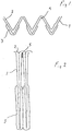
- Fig 1 shows the filter during the folding and fig 2 a blown up cross section of the filter at a glue string.
- the filter material 1 shown in the drawing has on its back side a glue string 2 that runs over the entire back side of the material and an intermittent glue string 3 applied to the front side of the filter material 1.
- the glue strings are in melt condition ejected on the extended filter material after this having been provided with folds. When then the folds are compressed to the position shown in fig 2 the still warm glue string sections that come in contact with each other will be glued to each other.
- the glue string 3 On the front side of the filter material the glue string 3 has interruptions corresponding to the inner sections of the folds so that possible flow channels 4 for the water 5 are obtained.
- the glue extends on the front of the filter down to half the depth of the folds.
- the filter material may advantageously be hydrophobic so that the water as droplets can run off the filter material down in the folds where it is collected to rivulets on the bottoms of the folds turned forwards and flow down to the lower end of the filter there to run off from the filter.
Landscapes
- Chemical & Material Sciences (AREA)
- Chemical Kinetics & Catalysis (AREA)
- Filtering Of Dispersed Particles In Gases (AREA)
- Fluid-Pressure Circuits (AREA)
- Control Of Throttle Valves Provided In The Intake System Or In The Exhaust System (AREA)
- Centrifugal Separators (AREA)
- Air Filters, Heat-Exchange Apparatuses, And Housings Of Air-Conditioning Units (AREA)
- Surgical Instruments (AREA)
- Lubrication Details And Ventilation Of Internal Combustion Engines (AREA)
- Filtering Materials (AREA)
- Folding Of Thin Sheet-Like Materials, Special Discharging Devices, And Others (AREA)
Abstract
Description
- At the use of filters with a high degree of separation in damp environment problems with pressure drop over the filter may arise. Since the filter in order to achieve the high degree of separation must have very small passage openings also very small water drops are stopped by the filter alternatively the filter is stopped up or clogged by the water due to the surface tension and adhesion of this to the filter material. Water in the shape of fog, rain or condensate will in this way block many of the flow passages through the filter, at which the reduced available flow area increase the pressure drop and through this the power losses in the filter. The removal of the water is to be sure welcome in many cases but having to increase the filter area as compensation as a result at installations where this can occur is particularly unwanted since it means a big increase in cost. Even if one choose not to increase the filter area an energy loss is obtained as a result of the increased pressure drop, which energy loss can be considerable.
- The invention has as its object to remedy the above problem by the use of a filter that is not influenced or at least only to a small amount as to the pressure drop by moisture and water in the air that is to be filtered. Examples of filter where these phenomena may arise are the inlet filter to gas turbines used for power supply at oil platforms, as well as of course other filters that are used on oil platforms, boats etc.
- In accordance with the invention this object is solved by the use defined in
claim 1. The filter to be used is constituted of a folded filter material held together by glue strings on both sides of the filter material. On one side of the filter material, the one that is to constitute the inlet side, the glue strings are interrupted corresponding to the inner end of the fold. Since the bottoms of the filter folds in this way become free the water can flow along the filter folds and is thus not stopped up in the filter. By arranging the filter with the filter folds vertically the water will under the influence of the gravity flow downwards in the bottom of the folds. The sides of the folds are inclined relative the flow direction of the entering air, which ensures that the water on the inner sides of the filter folds is driven away towards the bottom where then the continued transport out of the filter occurs. The water does thus no longer remain over a large part of the area of the filter but is collected in an efficiently draining channel that only covers a small part of the area of the filter, that therefor is not blocked to any appreciable degree by the water but allows a free passage of air, that is a low pressure drop and small energy losses. The glue strings (2) on the rear side of the filter material (1) are continuous. - One would at the filter arrangement according to the invention expect that the glue strings on the outlet side of the filter at the contraction of the filter material to its intended final form would compress the filter folds, that are turned towards the inlet side, completely in the inner end (bottom), since no resistance exist in the shape of a glue string, with impaired air flow as a result. In praxis it has however been discovered that this does not occur and that the filter still functions well during normal conditions and that it also functions well at moist or wet conditions. Likewise one would expect that the absence of glue as resistance on the inner side would give a more narrow fold that would in turn result in a very deep required "water channel" that thus would prevent air transport through a large part of the filter area, however this does not occur either. Even when viewing the filter is it hard to understand that the water transport can be so good as it in practice has turned out to be.
- One would further at the invented filter expect an impaired and too poor strength due to the reduced amount of glue. These filters have namely already at continuous glue strings on both sides a tendency to be broken, why they are normally arranged with the folds in the shortest dimension. It has however turned out that the filters according to the invention become stronger and even have a sufficient structural strength to be placed with the folds in the longest dimension. The reasons for this being possible are presumably several, among other things that the efficient draining of the water result in a reduced pressure drop and thereby a reduced strain. By arranging the folds in the length direction of the filter elements the filter folds will at the same time become vertical at the most usual installations of this kind and the water transport is thereby further enhanced by the gravity.
- The glue string on the rear side of the filter is when a pressure strain is applied on the filter (which normally is what breaks the filter) subjected to an extension strain that can be taken by the glue string on the back side that has been glued together. A possible inner glue string in the bottom of the fold does probably not contribute at all to the tensional strength since the filter material, that in this case have to transfer the tension strains, has difficult to do this since the tensional strain goes straight through the filter material. At such a strain one risk in reality that a glue string on the inner side of the filter not constitute any reinforcement but instead achieves a weakening that in the end result in the filter bursting. Dependent on for instance varying moistening and flow volume the pressure drop and the strain on the filter will vary with a membrane like movement for the filter as a result. If a glue string exist on the inside of the fold this result in alternating tensile strains on the filter material perpendicular to the surface of this. With time this movement loosens the filter material that has its strength as well as filtering properties reduced and in the end risk to break. The filter according to the invention is thus not as expected weakened but instead strengthened at the same time as the drainage of water is ensured.
- A possible tensile strain on the back side of the filter also opens the water channel constituted by the bottom of the fold with resulting improved flow and reduction of pressure drop and strain, presumably however this effect is very marginal.
- On the front side of the filter during influence of a pressure over the area of the filter a compressing force result and here glue in the folds can contribute to the strength. Nor does glue in these folds have any adverse effect on the water transport.
- In a preferable further development of the inventive thought the filter frame at the lower end of the filter folds is provided with openings or passages or inclined in order to prevent that water collects but instead successively can flow off from the filter when it flows down along the bottoms of the filter folds. In the extreme case one could even consider that the folded material at the lower end of the filter on the exit side of the filter is airtight glued or held only precisely behind a glue string on the rear side of the filter in such a way that the water without any hindrance can flow off downwards from the filter folds. (The filter folds on the back side being sealed at their lowest ends by a continuous glue string.) For reasons of strength the filter material may even be glued to the filter frame on the front side. Alternatively the frame may be provided with a slot along the bottoms of the filter folds for letting the water out. This version may also be used if the filter material is not hydrophobic but instead is moistened by the water, since the water in this case may flow or be transported inside the filter material itself down to the lower edge there to drop freely from the filter.
- Within the frame of the inventive thought one can also contemplate a nonsymmetric shape of the folds where the folds that are turned against the entering possibly wet air for the making of transport channels for water with greater cross section area are smother bent, resulting in a smaller part of the sides of the folds coming in contact with the water. Since the adhesion surface of the water at the filter also is reduced in this way the transport is also faster.
- Possibly the filter material need not to be folded at the bottoms of the channels but may instead be bent to the right shape. This can for instance be done by the tools for achieving the folds being differently sharp, for instance giving rounded half circle shape for the water channel bottoms.
- Alternatively the filter material at the bottom of the folds where water transport is to take place can be made wider by during the hardening of the glue on the rear side of the filter material holding this apart, either by the glue strings at the folds upper and forwards turned edges or by the preembossing of a smother fold corresponding to the bottom fold, that counteracts the glue pressure (from the other side). Also the applying of a moderate amount of glue on the rear side of the filter may function to this end so that the glue receives a small tendency to compress the fold at the bottom. Alternatively the glue on the rear side of the filter may have a higher temperature and thus less viscosity and pressure effect at the forming. Of course these measures can be combined.
- Further advantages and characteristics of the invention are apparent from an embodiment described below with reference to the enclosed drawing. Here
Fig 1 shows the filter during the folding andfig 2 a blown up cross section of the filter at a glue string. - The
filter material 1 shown in the drawing has on its back side aglue string 2 that runs over the entire back side of the material and anintermittent glue string 3 applied to the front side of thefilter material 1. The glue strings are in melt condition ejected on the extended filter material after this having been provided with folds. When then the folds are compressed to the position shown infig 2 the still warm glue string sections that come in contact with each other will be glued to each other. On the front side of the filter material theglue string 3 has interruptions corresponding to the inner sections of the folds so that possible flow channels 4 for thewater 5 are obtained. The glue extends on the front of the filter down to half the depth of the folds. The filter material may advantageously be hydrophobic so that the water as droplets can run off the filter material down in the folds where it is collected to rivulets on the bottoms of the folds turned forwards and flow down to the lower end of the filter there to run off from the filter.
Claims (4)
- Use of a filter for filtering air in a moist or wet environment, which filter comprises a folded filter material (1) that is held together by glue strings (2, 3) on front and rear sides of the filter material, wherein the filter during the use is mounted so that the folds are oriented vertically, the glue strings (2) on the front side of the filter material (1) being interrupted at the bottoms of the folds turned forwards establishing transport channels (4) for water at the bottom of each forward turned fold, so that water (5) easily can flow down and out from the filter in the channels (4), the transport being enhanced by the gravity, wherein the glue strings (2) on the rear side of the filter material (1) are in continuous.
- Use according to claim 1, characterized in that the glue strings (2, 3) on front and rear sides having at least some overlap.
- Use according to any of the preceding claims characterized in that a filter frame is arranged with openings at the front side of the filter so that water (5) flowing along the bottoms of the folds easily can run on out from the filter.
- Use according to any of the preceding claims, characterized in the glue strings on the front side of the filter material being interrupted a measure corresponding to 1/10 - 9/10 of the depth of the filter.
Applications Claiming Priority (2)
| Application Number | Priority Date | Filing Date | Title |
|---|---|---|---|
| SE9800993A SE512385C2 (en) | 1998-03-25 | 1998-03-25 | Air filter of pleated filter material and methods for its manufacture |
| SE9800993 | 1998-03-25 |
Publications (3)
| Publication Number | Publication Date |
|---|---|
| EP0948986A1 EP0948986A1 (en) | 1999-10-13 |
| EP0948986B1 EP0948986B1 (en) | 2007-04-04 |
| EP0948986B2 true EP0948986B2 (en) | 2017-03-01 |
Family
ID=20410681
Family Applications (1)
| Application Number | Title | Priority Date | Filing Date |
|---|---|---|---|
| EP99850044.1A Expired - Lifetime EP0948986B2 (en) | 1998-03-25 | 1999-03-23 | Folded Filter |
Country Status (7)
| Country | Link |
|---|---|
| US (1) | US6176890B1 (en) |
| EP (1) | EP0948986B2 (en) |
| AT (1) | ATE358523T1 (en) |
| DE (1) | DE69935688T2 (en) |
| MY (1) | MY125620A (en) |
| NO (1) | NO310635B1 (en) |
| SE (1) | SE512385C2 (en) |
Families Citing this family (12)
| Publication number | Priority date | Publication date | Assignee | Title |
|---|---|---|---|---|
| DE10015951C2 (en) * | 1999-12-22 | 2002-09-26 | Jacobi Systemtechnik Gmbh | filter element |
| WO2001072399A1 (en) * | 2000-03-24 | 2001-10-04 | Camfil Ab | Folded filter |
| DE10107634A1 (en) * | 2001-02-15 | 2002-08-22 | Mhb Filtration Gmbh & Co Kg | Filter element formed of pleated filter medium, e.g. for motor vehicle fresh air supply, is formed from pleated filter medium with adhesive tracks or reinforcing members which are arranged to enable bending of filter element |
| US6699348B2 (en) | 2001-04-13 | 2004-03-02 | Camfil Ab | Method for filter fabrication |
| JP4361263B2 (en) * | 2002-02-07 | 2009-11-11 | 本田技研工業株式会社 | Filter element |
| DE102007012721A1 (en) * | 2007-03-14 | 2008-09-25 | Atex-Filter Gmbh | Gas turbine's air supply filter for use in power generating plant, has frame with fluid collecting device arranged at lower section in fitting position and formed by bowl-like profile of frame |
| US7972402B2 (en) * | 2008-07-17 | 2011-07-05 | Mann + Hummel Gmbh | Reinforced filter element |
| US8137427B2 (en) * | 2009-03-17 | 2012-03-20 | Mann & Hummel Gmbh | Filter element with pleat support combs |
| DE102009040202B4 (en) * | 2009-09-07 | 2015-10-01 | Mann + Hummel Gmbh | filter |
| DE102014009886B4 (en) | 2014-07-04 | 2026-05-13 | Mann+Hummel Gmbh | Filter element for filtering media |
| CN202786257U (en) * | 2011-08-31 | 2013-03-13 | 通用电气健康护理生物科学股份公司 | Exhaust filtration device for bioreactor |
| DE102019115568A1 (en) | 2019-06-07 | 2020-12-10 | Mann+Hummel Gmbh | Filter element and filter system |
Family Cites Families (12)
| Publication number | Priority date | Publication date | Assignee | Title |
|---|---|---|---|---|
| GB1272564A (en) * | 1968-09-30 | 1972-05-03 | Marshall D A G | Improvements in or relating to fluid filters |
| US4135900A (en) * | 1977-05-31 | 1979-01-23 | American Air Filter Company, Inc. | Gas filter device |
| US4227953A (en) * | 1977-12-02 | 1980-10-14 | Cambridge Filter Corp. | Method of fabricating air filters |
| DE3037019C2 (en) * | 1980-10-01 | 1986-01-09 | Drägerwerk AG, 2400 Lübeck | HEPA filter insert made of folded HEPA filter material for HEPA filters and a process for its manufacture |
| DE3219671A1 (en) * | 1982-05-26 | 1983-12-01 | Peter A. 8909 Neuburg Walther | Filter |
| US4615804A (en) * | 1984-08-30 | 1986-10-07 | Donaldson Company, Inc. | High density pleat spacing and scoring tool and filter made therewith |
| DE3542963A1 (en) * | 1985-12-05 | 1987-06-11 | Kernforschungsz Karlsruhe | FILTER PACK |
| DE68911665T2 (en) * | 1989-01-05 | 1994-07-07 | Camfil Ab | Filter. |
| US5236480A (en) | 1989-01-05 | 1993-08-17 | Camfil Ab | Air filter for workstations and methods of making and using such air filter |
| WO1995017943A2 (en) * | 1993-12-30 | 1995-07-06 | Detroit Holding Limited | Filter insert and process for producing the same |
| US5744036A (en) * | 1997-02-03 | 1998-04-28 | Aaf International | Pleated filter arrangement |
| US6036752A (en) * | 1998-07-28 | 2000-03-14 | 3M Innovative Properties Company | Pleated filter |
-
1998
- 1998-03-25 SE SE9800993A patent/SE512385C2/en not_active IP Right Cessation
-
1999
- 1999-03-23 AT AT99850044T patent/ATE358523T1/en not_active IP Right Cessation
- 1999-03-23 EP EP99850044.1A patent/EP0948986B2/en not_active Expired - Lifetime
- 1999-03-23 DE DE69935688T patent/DE69935688T2/en not_active Expired - Lifetime
- 1999-03-24 NO NO19991415A patent/NO310635B1/en not_active IP Right Cessation
- 1999-03-24 MY MYPI99001105A patent/MY125620A/en unknown
- 1999-03-26 US US09/277,349 patent/US6176890B1/en not_active Expired - Lifetime
Also Published As
| Publication number | Publication date |
|---|---|
| ATE358523T1 (en) | 2007-04-15 |
| NO310635B1 (en) | 2001-07-30 |
| SE512385C2 (en) | 2000-03-06 |
| EP0948986A1 (en) | 1999-10-13 |
| NO991415D0 (en) | 1999-03-24 |
| EP0948986B1 (en) | 2007-04-04 |
| US6176890B1 (en) | 2001-01-23 |
| MY125620A (en) | 2006-08-30 |
| NO991415L (en) | 1999-09-27 |
| DE69935688T2 (en) | 2007-12-27 |
| DE69935688D1 (en) | 2007-05-16 |
| SE9800993L (en) | 1999-09-26 |
| SE9800993D0 (en) | 1998-03-25 |
Similar Documents
| Publication | Publication Date | Title |
|---|---|---|
| EP0948986B1 (en) | Folded Filter | |
| US10823451B2 (en) | Louver assembly | |
| JP5592471B2 (en) | Filter cassette, filter arrangement structure and gas turbine equipped with such a filter cassette | |
| US20110154789A1 (en) | Method of Making a Marine Gas Turbine Filter | |
| BR0101087B1 (en) | filter cartridge. | |
| KR950031365A (en) | Receiver and Dryer | |
| US3438505A (en) | Filter segment for disc filters | |
| FR2806641A1 (en) | FLEXIBLE PLEATED FILTER ELEMENT WITH REINFORCEMENT DURING BENDING | |
| US20120204524A1 (en) | Vacuum cleaner bag | |
| NL8001437A (en) | FOLDABLE RUBBER DAM. | |
| CN1103237C (en) | Sintered plastic particles filter element | |
| WO1995026803B1 (en) | High capacity marine separator | |
| EP0119111A1 (en) | Belt filter containing an air suction device | |
| US539800A (en) | Pump-strainer | |
| CN205095658U (en) | Film element | |
| ITPD20080270A1 (en) | FILTERING SYSTEM WITH REPLACEABLE CARTRIDGE | |
| EP1957720B1 (en) | Separator for removing impurities, especially smaller particles from rain water | |
| FR2670718A1 (en) | FRESH AIR SUCTION CHANNEL FOR A MOTOR VEHICLE. | |
| WO2011004069A1 (en) | A gas filtering device and a method of manufaturing a gas filtering device | |
| JP3804310B2 (en) | Air intake duct structure | |
| EP0317674A2 (en) | High efficiency particulate air filter and spacer therefor | |
| KR102678405B1 (en) | Air filter for vehicles | |
| EP0132872B1 (en) | Ventilation appliance | |
| CN214286799U (en) | A water-oil separation device | |
| US896360A (en) | Vacuum filtering apparatus. |
Legal Events
| Date | Code | Title | Description |
|---|---|---|---|
| PUAI | Public reference made under article 153(3) epc to a published international application that has entered the european phase |
Free format text: ORIGINAL CODE: 0009012 |
|
| AK | Designated contracting states |
Kind code of ref document: A1 Designated state(s): AT BE CY DE DK ES FI FR GB GR IE IT LU MC NL PT SE |
|
| AX | Request for extension of the european patent |
Free format text: AL;LT;LV;MK;RO;SI |
|
| AKX | Designation fees paid | ||
| 17P | Request for examination filed |
Effective date: 20000413 |
|
| RBV | Designated contracting states (corrected) |
Designated state(s): AT BE CY DE DK ES FI FR GB GR IE IT LU MC NL PT SE |
|
| REG | Reference to a national code |
Ref country code: DE Ref legal event code: 8566 |
|
| 17Q | First examination report despatched |
Effective date: 20031030 |
|
| GRAP | Despatch of communication of intention to grant a patent |
Free format text: ORIGINAL CODE: EPIDOSNIGR1 |
|
| RIN1 | Information on inventor provided before grant (corrected) |
Inventor name: SVEDLIND, THOMAS Inventor name: LANS, ERIK |
|
| GRAS | Grant fee paid |
Free format text: ORIGINAL CODE: EPIDOSNIGR3 |
|
| GRAA | (expected) grant |
Free format text: ORIGINAL CODE: 0009210 |
|
| AK | Designated contracting states |
Kind code of ref document: B1 Designated state(s): AT BE CY DE DK ES FI FR GB GR IE IT LU MC NL PT SE |
|
| PG25 | Lapsed in a contracting state [announced via postgrant information from national office to epo] |
Ref country code: FI Free format text: LAPSE BECAUSE OF FAILURE TO SUBMIT A TRANSLATION OF THE DESCRIPTION OR TO PAY THE FEE WITHIN THE PRESCRIBED TIME-LIMIT Effective date: 20070404 |
|
| REG | Reference to a national code |
Ref country code: GB Ref legal event code: FG4D |
|
| REF | Corresponds to: |
Ref document number: 69935688 Country of ref document: DE Date of ref document: 20070516 Kind code of ref document: P |
|
| REG | Reference to a national code |
Ref country code: IE Ref legal event code: FG4D |
|
| PG25 | Lapsed in a contracting state [announced via postgrant information from national office to epo] |
Ref country code: ES Free format text: LAPSE BECAUSE OF FAILURE TO SUBMIT A TRANSLATION OF THE DESCRIPTION OR TO PAY THE FEE WITHIN THE PRESCRIBED TIME-LIMIT Effective date: 20070715 |
|
| REG | Reference to a national code |
Ref country code: SE Ref legal event code: TRGR |
|
| PG25 | Lapsed in a contracting state [announced via postgrant information from national office to epo] |
Ref country code: PT Free format text: LAPSE BECAUSE OF FAILURE TO SUBMIT A TRANSLATION OF THE DESCRIPTION OR TO PAY THE FEE WITHIN THE PRESCRIBED TIME-LIMIT Effective date: 20070904 |
|
| NLV1 | Nl: lapsed or annulled due to failure to fulfill the requirements of art. 29p and 29m of the patents act | ||
| ET | Fr: translation filed | ||
| PG25 | Lapsed in a contracting state [announced via postgrant information from national office to epo] |
Ref country code: AT Free format text: LAPSE BECAUSE OF FAILURE TO SUBMIT A TRANSLATION OF THE DESCRIPTION OR TO PAY THE FEE WITHIN THE PRESCRIBED TIME-LIMIT Effective date: 20070404 |
|
| PG25 | Lapsed in a contracting state [announced via postgrant information from national office to epo] |
Ref country code: BE Free format text: LAPSE BECAUSE OF FAILURE TO SUBMIT A TRANSLATION OF THE DESCRIPTION OR TO PAY THE FEE WITHIN THE PRESCRIBED TIME-LIMIT Effective date: 20070404 |
|
| PLBI | Opposition filed |
Free format text: ORIGINAL CODE: 0009260 |
|
| PG25 | Lapsed in a contracting state [announced via postgrant information from national office to epo] |
Ref country code: NL Free format text: LAPSE BECAUSE OF FAILURE TO SUBMIT A TRANSLATION OF THE DESCRIPTION OR TO PAY THE FEE WITHIN THE PRESCRIBED TIME-LIMIT Effective date: 20070404 |
|
| PLAX | Notice of opposition and request to file observation + time limit sent |
Free format text: ORIGINAL CODE: EPIDOSNOBS2 |
|
| 26 | Opposition filed |
Opponent name: W. L. GORE & ASSOCIATES GMBH Effective date: 20080103 |
|
| PG25 | Lapsed in a contracting state [announced via postgrant information from national office to epo] |
Ref country code: GR Free format text: LAPSE BECAUSE OF FAILURE TO SUBMIT A TRANSLATION OF THE DESCRIPTION OR TO PAY THE FEE WITHIN THE PRESCRIBED TIME-LIMIT Effective date: 20070705 |
|
| PLAF | Information modified related to communication of a notice of opposition and request to file observations + time limit |
Free format text: ORIGINAL CODE: EPIDOSCOBS2 |
|
| PLBB | Reply of patent proprietor to notice(s) of opposition received |
Free format text: ORIGINAL CODE: EPIDOSNOBS3 |
|
| PG25 | Lapsed in a contracting state [announced via postgrant information from national office to epo] |
Ref country code: MC Free format text: LAPSE BECAUSE OF NON-PAYMENT OF DUE FEES Effective date: 20080331 |
|
| EUG | Se: european patent has lapsed | ||
| PG25 | Lapsed in a contracting state [announced via postgrant information from national office to epo] |
Ref country code: SE Free format text: LAPSE BECAUSE OF NON-PAYMENT OF DUE FEES Effective date: 20080324 Ref country code: IE Free format text: LAPSE BECAUSE OF NON-PAYMENT OF DUE FEES Effective date: 20080324 |
|
| PG25 | Lapsed in a contracting state [announced via postgrant information from national office to epo] |
Ref country code: CY Free format text: LAPSE BECAUSE OF FAILURE TO SUBMIT A TRANSLATION OF THE DESCRIPTION OR TO PAY THE FEE WITHIN THE PRESCRIBED TIME-LIMIT Effective date: 20070404 |
|
| PG25 | Lapsed in a contracting state [announced via postgrant information from national office to epo] |
Ref country code: DK Free format text: LAPSE BECAUSE OF FAILURE TO SUBMIT A TRANSLATION OF THE DESCRIPTION OR TO PAY THE FEE WITHIN THE PRESCRIBED TIME-LIMIT Effective date: 20070404 |
|
| PG25 | Lapsed in a contracting state [announced via postgrant information from national office to epo] |
Ref country code: LU Free format text: LAPSE BECAUSE OF NON-PAYMENT OF DUE FEES Effective date: 20080323 |
|
| RDAF | Communication despatched that patent is revoked |
Free format text: ORIGINAL CODE: EPIDOSNREV1 |
|
| APAH | Appeal reference modified |
Free format text: ORIGINAL CODE: EPIDOSCREFNO |
|
| APBM | Appeal reference recorded |
Free format text: ORIGINAL CODE: EPIDOSNREFNO |
|
| APBP | Date of receipt of notice of appeal recorded |
Free format text: ORIGINAL CODE: EPIDOSNNOA2O |
|
| APBQ | Date of receipt of statement of grounds of appeal recorded |
Free format text: ORIGINAL CODE: EPIDOSNNOA3O |
|
| APBU | Appeal procedure closed |
Free format text: ORIGINAL CODE: EPIDOSNNOA9O |
|
| RAP2 | Party data changed (patent owner data changed or rights of a patent transferred) |
Owner name: CAMFIL AB |
|
| REG | Reference to a national code |
Ref country code: FR Ref legal event code: PLFP Year of fee payment: 17 |
|
| PLAY | Examination report in opposition despatched + time limit |
Free format text: ORIGINAL CODE: EPIDOSNORE2 |
|
| PLAH | Information related to despatch of examination report in opposition + time limit modified |
Free format text: ORIGINAL CODE: EPIDOSCORE2 |
|
| PLBC | Reply to examination report in opposition received |
Free format text: ORIGINAL CODE: EPIDOSNORE3 |
|
| REG | Reference to a national code |
Ref country code: FR Ref legal event code: PLFP Year of fee payment: 18 |
|
| RIC2 | Information provided on ipc code assigned after grant |
Ipc: B01D 46/52 20060101ALI20160216BHEP Ipc: B01D 46/00 20060101AFI20160216BHEP |
|
| PUAH | Patent maintained in amended form |
Free format text: ORIGINAL CODE: 0009272 |
|
| STAA | Information on the status of an ep patent application or granted ep patent |
Free format text: STATUS: PATENT MAINTAINED AS AMENDED |
|
| 27A | Patent maintained in amended form |
Effective date: 20170301 |
|
| AK | Designated contracting states |
Kind code of ref document: B2 Designated state(s): AT BE CY DE DK ES FI FR GB GR IE IT LU MC NL PT SE |
|
| REG | Reference to a national code |
Ref country code: DE Ref legal event code: R102 Ref document number: 69935688 Country of ref document: DE |
|
| REG | Reference to a national code |
Ref country code: FR Ref legal event code: PLFP Year of fee payment: 19 |
|
| PGFP | Annual fee paid to national office [announced via postgrant information from national office to epo] |
Ref country code: DE Payment date: 20170322 Year of fee payment: 19 |
|
| REG | Reference to a national code |
Ref country code: DE Ref legal event code: R135 Ref document number: 69935688 Country of ref document: DE |
|
| PG25 | Lapsed in a contracting state [announced via postgrant information from national office to epo] |
Ref country code: DE Free format text: LAPSE BECAUSE OF FAILURE TO SUBMIT A TRANSLATION OF THE DESCRIPTION OR TO PAY THE FEE WITHIN THE PRESCRIBED TIME-LIMIT Effective date: 20170602 |
|
| REG | Reference to a national code |
Ref country code: FR Ref legal event code: PLFP Year of fee payment: 20 |
|
| PGFP | Annual fee paid to national office [announced via postgrant information from national office to epo] |
Ref country code: GB Payment date: 20180321 Year of fee payment: 20 |
|
| PGFP | Annual fee paid to national office [announced via postgrant information from national office to epo] |
Ref country code: FR Payment date: 20180323 Year of fee payment: 20 |
|
| PGFP | Annual fee paid to national office [announced via postgrant information from national office to epo] |
Ref country code: IT Payment date: 20180326 Year of fee payment: 20 |
|
| RDAF | Communication despatched that patent is revoked |
Free format text: ORIGINAL CODE: EPIDOSNREV1 |
|
| REG | Reference to a national code |
Ref country code: GB Ref legal event code: PE20 Expiry date: 20190322 |
|
| RDAE | Information deleted related to despatch of communication that patent is revoked |
Free format text: ORIGINAL CODE: EPIDOSDREV1 |
|
| PG25 | Lapsed in a contracting state [announced via postgrant information from national office to epo] |
Ref country code: GB Free format text: LAPSE BECAUSE OF EXPIRATION OF PROTECTION Effective date: 20190322 |